EP1710930A1 - Communication terminal device and communication relay method - Google Patents
Communication terminal device and communication relay method Download PDFInfo
- Publication number
- EP1710930A1 EP1710930A1 EP05720272A EP05720272A EP1710930A1 EP 1710930 A1 EP1710930 A1 EP 1710930A1 EP 05720272 A EP05720272 A EP 05720272A EP 05720272 A EP05720272 A EP 05720272A EP 1710930 A1 EP1710930 A1 EP 1710930A1
- Authority
- EP
- European Patent Office
- Prior art keywords
- communication
- data
- relay
- communication terminal
- station
- Prior art date
- Legal status (The legal status is an assumption and is not a legal conclusion. Google has not performed a legal analysis and makes no representation as to the accuracy of the status listed.)
- Withdrawn
Links
Images





Classifications
-
- H—ELECTRICITY
- H04—ELECTRIC COMMUNICATION TECHNIQUE
- H04B—TRANSMISSION
- H04B7/00—Radio transmission systems, i.e. using radiation field
- H04B7/14—Relay systems
- H04B7/15—Active relay systems
- H04B7/155—Ground-based stations
- H04B7/15528—Control of operation parameters of a relay station to exploit the physical medium
- H04B7/15542—Selecting at relay station its transmit and receive resources
-
- H—ELECTRICITY
- H04—ELECTRIC COMMUNICATION TECHNIQUE
- H04W—WIRELESS COMMUNICATION NETWORKS
- H04W88/00—Devices specially adapted for wireless communication networks, e.g. terminals, base stations or access point devices
- H04W88/02—Terminal devices
- H04W88/04—Terminal devices adapted for relaying to or from another terminal or user
-
- H—ELECTRICITY
- H04—ELECTRIC COMMUNICATION TECHNIQUE
- H04L—TRANSMISSION OF DIGITAL INFORMATION, e.g. TELEGRAPHIC COMMUNICATION
- H04L25/00—Baseband systems
- H04L25/02—Details ; arrangements for supplying electrical power along data transmission lines
- H04L25/20—Repeater circuits; Relay circuits
-
- H—ELECTRICITY
- H04—ELECTRIC COMMUNICATION TECHNIQUE
- H04L—TRANSMISSION OF DIGITAL INFORMATION, e.g. TELEGRAPHIC COMMUNICATION
- H04L27/00—Modulated-carrier systems
- H04L27/26—Systems using multi-frequency codes
-
- H—ELECTRICITY
- H04—ELECTRIC COMMUNICATION TECHNIQUE
- H04L—TRANSMISSION OF DIGITAL INFORMATION, e.g. TELEGRAPHIC COMMUNICATION
- H04L5/00—Arrangements affording multiple use of the transmission path
- H04L5/003—Arrangements for allocating sub-channels of the transmission path
- H04L5/0032—Distributed allocation, i.e. involving a plurality of allocating devices, each making partial allocation
-
- H—ELECTRICITY
- H04—ELECTRIC COMMUNICATION TECHNIQUE
- H04L—TRANSMISSION OF DIGITAL INFORMATION, e.g. TELEGRAPHIC COMMUNICATION
- H04L5/00—Arrangements affording multiple use of the transmission path
- H04L5/0091—Signalling for the administration of the divided path, e.g. signalling of configuration information
- H04L5/0094—Indication of how sub-channels of the path are allocated
-
- H—ELECTRICITY
- H04—ELECTRIC COMMUNICATION TECHNIQUE
- H04W—WIRELESS COMMUNICATION NETWORKS
- H04W52/00—Power management, e.g. Transmission Power Control [TPC] or power classes
- H04W52/02—Power saving arrangements
-
- H—ELECTRICITY
- H04—ELECTRIC COMMUNICATION TECHNIQUE
- H04B—TRANSMISSION
- H04B1/00—Details of transmission systems, not covered by a single one of groups H04B3/00 - H04B13/00; Details of transmission systems not characterised by the medium used for transmission
- H04B1/69—Spread spectrum techniques
- H04B1/713—Spread spectrum techniques using frequency hopping
-
- H—ELECTRICITY
- H04—ELECTRIC COMMUNICATION TECHNIQUE
- H04L—TRANSMISSION OF DIGITAL INFORMATION, e.g. TELEGRAPHIC COMMUNICATION
- H04L5/00—Arrangements affording multiple use of the transmission path
- H04L5/0001—Arrangements for dividing the transmission path
- H04L5/0003—Two-dimensional division
- H04L5/0005—Time-frequency
- H04L5/0007—Time-frequency the frequencies being orthogonal, e.g. OFDM(A) or DMT
-
- Y—GENERAL TAGGING OF NEW TECHNOLOGICAL DEVELOPMENTS; GENERAL TAGGING OF CROSS-SECTIONAL TECHNOLOGIES SPANNING OVER SEVERAL SECTIONS OF THE IPC; TECHNICAL SUBJECTS COVERED BY FORMER USPC CROSS-REFERENCE ART COLLECTIONS [XRACs] AND DIGESTS
- Y02—TECHNOLOGIES OR APPLICATIONS FOR MITIGATION OR ADAPTATION AGAINST CLIMATE CHANGE
- Y02D—CLIMATE CHANGE MITIGATION TECHNOLOGIES IN INFORMATION AND COMMUNICATION TECHNOLOGIES [ICT], I.E. INFORMATION AND COMMUNICATION TECHNOLOGIES AIMING AT THE REDUCTION OF THEIR OWN ENERGY USE
- Y02D30/00—Reducing energy consumption in communication networks
- Y02D30/70—Reducing energy consumption in communication networks in wireless communication networks
Definitions
- the present invention relates to a communication terminal apparatus and communication relay method in a multihop system adopting an OFDM (Orthogonal Frequency Division Multiplex) scheme.
- OFDM Orthogonal Frequency Division Multiplex
- each communication terminal has a communication relay function and relays communication between another communication terminal and a base station. Therefore, a communication terminal that is located outside the communication area (outside a cell) and cannot directly communicate with the base station (hereinafter referred to as a "relay requesting station”) requests another communication terminal that can directly communicate with the base station to relay communication. Then, the communication terminal requested to relay communication (hereinafter referred to as a "relay station”) establishes a link to the base station, and relays communication between the communication terminal outside the area and the base station. By this means, the communication terminal outside the area can communicate with the base station.
- Patent Document 1 Japanese Patent Application Laid-Open No.HEI11-289349
- a communication terminal apparatus of the present invention that relays communication between a base station and another communication terminal in a communication system of an OFDM scheme, adopts a configuration having: a storage section that stores communication data between the base station and another communication terminal; and a transmission section that frequency division multiplexes the stored communication data with data of the communication terminal apparatus and transmits the frequency division multiplexed data at a timing for transmitting the data of the communication terminal apparatus.
- a communication system of the present invention is a communication system of an OFDM scheme having a base station and a plurality of communication terminals, wherein, when a first communication terminal is requested to relay communication with the base station from a second communication terminal, the first communication terminal temporarily stores relay data and frequency division multiplexes the relay data with data of the first communication terminal, transmits the frequency division multiplexed data at a timing for transmitting the data of the first communication terminal, and reports the relay to the second communication terminal, and, when the second communication terminal receives the report of the relay from the first communication terminal, the second communication terminal reports the relay to a user of the second communication terminal.
- the present invention in the multihop system, it is possible to relay communication between a communication terminal located outside the area and a base station, and suppress increase in power consumption of the communication terminal.
- One aspect of the present invention is that, in the multihop system, even when a mobile station is requested to perform a relay from another mobile station, the mobile station does not always perform the relay, and the cases of performing a relay are limited.
- the mobile station according to Embodiment 1 of the present invention is located in a location where direct communication with a base station is possible in the multipop system adopting an OFDM-TDD (Orthogonal Frequency Division Multiplex ⁇ Time Division Duplex) system.
- OFDM-TDD Orthogonal Frequency Division Multiplex ⁇ Time Division Duplex
- the mobile station performs a relay in the following limited cases.
- uplink relay uplink communication between a mobile station outside the area and a base station
- downlink communication between a mobile station outside the area and the base station is referred to as "downlink relay”
- uplink relay and downlink relay will be explained separately.
- FIG. 1 illustrates a case in which mobile station (relay station) MS1 within a cell relays uplink communication between mobile station (relay requesting station) MS2 located outside cell A1 and base station BS1, that is, a case of uplink relay.
- mobile station MS1 In uplink, the cases in which mobile station MS1 performs relay are limited as follows. That is, at the timing when mobile station MS1 transmits data to base station BS1, mobile station MS1 relays transmission data from mobile station MS2 to base station BS1. To be more specific, mobile station MS1 transmits transmission data S2 transmitted from mobile station MS2 to base station BS1 together with transmission data S1 of mobile station MS1.
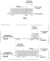
- FIG.2A to FIG.2C illustrate a timing when mobile station MS1 relays data of mobile station MS2.
- FIG.2A shows uplink communication/downlink communication timings between base station BS1 and mobile station MS1, that is, uplink communication/downlink communication timings in a TDD system.
- downward arrows indicate downlink communication
- upward arrows indicate uplink communication.
- FIG.2B shows a transmission signal of mobile station MS2 outside the area (received signal of relay station MS1)
- FIG.2C shows a transmission signal of relay station MS1.
- mobile station MS2 transmits data S2 for base station BS1 to mobile station MS1 at downlink communication timing t1 in a cellular system (TDD system) of base station BS1.
- TDD system cellular system
- mobile station MS2 does not necessarily have to be synchronized.
- Mobile station MS1 receives data S2 and temporarily stores data S2 in a buffer. Then, as shown in FIG.2C, after waiting until timing t4 of transmitting data S1 of mobile station MS1 comes, and at timing t4, mobile station MS1 multiplexes data S2 stored in the buffer with data S1 of mobile station MS1 and transmits the multiplexed data to base station BS1. When a waiting time of the data relay exceeds a predetermined time, mobile station MS1 discards this relay data and does not perform relay.
- mobile station MS1 confirms whether or not there is an unused subcarrier in OFDM frequencies, that is, a subcarrier to which transmission data for base station BS1 of mobile station MS1 or a control channel signal is not mapped among available subcarriers when mobile station MS1 performs transmission (available subcarrier). Then, if there is an available subcarrier, mobile station MS1 determines whether the available subcarrier has enough capacity for a data relay (whether the capacity of available subcarrier is larger than the size of relay data). If there is not enough capacity for a data relay, mobile station MS1 does not perform a relay.
- FIG.3 shows an example of a usage state of transmission subcarriers for relay station MS1.
- subcarriers having center frequencies f1 to f12 are subcarriers to which transmission data of mobile station MS1 is mapped (subcarreirs for MS1), and a subcarrier of center frequency f17 is a subcarrier to which a control channel is mapped. Therefore, subcarriers having center frequencies f13 to f16 are the above-described available subcarriers.
- mobile station MS1 confirms the capacity of these available subcarriers and relays communication between mobile station MS2 and base station BS1.
- mobile station MS1 maps data which is requested to be transmitted from mobile station MS2 to base station BS1, to the above-described available subcarriers.
- mobile station MS1 maps data of mobile station MS2 to subcarriers with the frequency as it is.
- mobile station MS1 After mobile station MS1 multiplexes subcarriers to which data of mobile station MS2 is mapped with subcarriers to which data of mobile station MS1 is mapped and obtains a multicarrier signal, mobile station MS1 transmits this multicarrier signal to base station BS1.
- FIG. 4 shows an example of a relationship between transmission subcarriers for mobile station (relay requesting station) MS2 outside the area and available subcarriers for relay station MS1, that is, a case in which both subcarriers have the above relationship.
- FIG.4A shows transmission subcarriers for mobile station (relay requesting station) MS2
- FIG.4B shows available subcarriers for relay station MS1.
- the range of center frequencies of transmission subcarriers for mobile station MS2 outside the area is between f13 and f16
- the range of center frequencies of available subcarriers for relay station MS1 is between f1 and f6.
- the frequencies of transmission subcarriers for a mobile station which requests a relay are not always covered (included) by the frequencies of available subcarriers for the relay station.
- relay station MS1 maintains (fixes) the frequencies of transmission subcarriers for relay station MS1, and shifts the frequencies of transmission subcarriers for relay data so that the frequencies of transmission subcarriers for the relay data are included within the frequency range of available subcarriers.
- the range of center frequencies of relay data subcarriers change from f13 and f16 to f1 and f6.
- mobile station MS1 can smoothly relay data.
- relay station MS1 does not change the frequencies of transmission subcarriers for relay station MS1, for example, even in a communication system such as frequency scheduling in which subcarriers are assigned to use in advance to each mobile station, the frequency scheduling functions effectively.
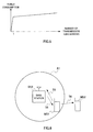
- FIG.5 shows a relationship between the number of transmission subcarriers for a mobile station and power consumption.
- mobile station MS1 when mobile station MS1 performs transmission--that is, when the number of transmission subcarriers is 1 or more--mobile station (relay station) MS1 according to this embodiment maps data of another station (such as mobile station MS2) to available subcarriers and transmits the subcarriers. If such transmission is performed, it can be seen from FIG.5 that power consumption of mobile station MS1 increases little. Furthermore, as described above, relay station MS1 continues mapping relay data to available subcarriers, and does not change the frequencies of transmission subcarriers for relay station MS1. That is, even if relay station MS1 has a function of relaying data, relay station MS1 transmits data of relay station MS1 as a first priority. Therefore, it can be seen that relay station MS1 is influenced little by relaying data.
- FIG.6 illustrates a case in which mobile station (relay station) MS1 within the cell relays downlink communication between mobile station (relay requesting station) MS2 outside the area and base station BS1, that is, a case of downlink relay.
- mobile station MS1 In downlink, cases in which mobile station MS1 performs relay are limited as follows. That is, at the timing when mobile station MS1 transmits data to base station BS1, mobile station MS1 relays transmission data for mobile station MS2 from base station BS1. To be more specific, mobile station MS1 transmits transmission data S6 transmitted from base station BS1 to mobile station MS2 at the same timing as the timing for transmission data S5 of mobile station MS1.
- FIGs.7A to 7C illustrate a timing when mobile station MS1 relays data of base station BS1.
- FIG.7A shows uplink communication/downlink communication timings in a TDD system. Furthermore, FIG.7B shows a transmission signal of base station BS1 (received signal at relay station MS1), and FIG.7C shows a transmission signal at relay station MS1.
- base station BS1 transmits data S6 for mobile station MS2 to mobile station MS1.
- Mobile station MS1 receives this data S6 and temporarily stores data S6 in a buffer.
- FIG. 7C after waiting until the timing for transmitting data S5 of mobile station MS1 to base station BS1--that is, uplink communication timing t14--and at this timing t14, mobile station MS1 multiplexes relay data S6 stored in the buffer with data S5 of mobile station MS1 and transmits the multiplexed data.
- Relay data S6 is downlink relay data though transmitted at uplink communication timing t14. Therefore, mobile station MS2 receiving this relay data S6 needs to perform reception processing at an uplink communication timing.
- mobile station MS1 determines whether or not there is an available subcarrier in OFDM frequencies.
- FIG.8 shows an example of a usage state of transmission subcarriers for relay station MS1.
- subcarriers for center frequencies f13 to f16 are available subcarriers (subcarriers for base station BS1). Then, mobile station MS1 maps data for mobile station MS2 from base station BS1 to the available subcarriers, and multiplexes the subcarriers with subcarriers to which data for base station BS1 frommobile station MS1 is mapped and transmits the subcarriers.
- FIG.9 is a block diagram showing a main configuration of mobile station MS1 (mobile station apparatus 100) according to this embodiment implementing the above-described operations.
- Sections of this mobile station apparatus 100 implement the following operations:
- Antenna 101 receives a radio signal from another station (base station BS1 or another mobile station such as mobile station MS2), and transmits a radio signal from mobile station MS1.
- TDD switch 102 switches between transmission and reception of the radio signal in synchronization with uplink/downlink timings in the TDD system.
- Reception RF section 103 performs predetermined radio reception processing such as down-conversion on the radio signal received via antenna 101, and obtains a baseband signal.
- OFDM reception section 104 performs predetermined OFDM reception processing such as inverse fast Fourier transform (IFFT) on the baseband signal, and obtains subcarrier signals from the multicarrier baseband signal.
- IFFT inverse fast Fourier transform
- Frequency separation section 105 separates subcarrier signals by frequency (refer to FIG.3 and FIG. 8), and separates data for mobile station MS1 from data for another station.
- Subject-station data channel demodulation section 106 demodulates data for mobile station MS1 and obtains received data for mobile station MS1.
- Other-station data channel demodulation section 107 demodulates data for another station and temporarily stores this demodulated data in buffer 108.
- buffer 111 temporarily stores the data.
- Transmission timing determination section 112 determines a timing for transmitting data of mobile station MS1 in accordance with the uplink/downlink timing in the TDD system, reads the stored transmission data from buffer 111 according to this timing, and outputs the transmission data to transmission frequency determination section 113. Furthermore, transmission timing determination section 112 reports the transmission timing of mobile station MS1 to buffer 108.
- Transmission frequency determination section 113 determines frequencies (subcarriers) needed to transmit this data based on the transmission data size or the like outputted from transmission timing determination section 112, and determines subcarriers needed to transmit a control channel. Furthermore, when there are available subcarriers as already described using FIG.3 and FIG.8, transmission frequency determination section 113 reports the presence of available subcarriers and information about these available subcarriers to other-station data channel modulation section 114. Furthermore, transmission frequency determination section 113 reports information about the subcarriers use by mobile station MS1 and available subcarriers, to control channel generation section 115.
- Buffer 108 outputs the stored data for another station to other-station data channel modulation section 114 based on the transmission timing of mobile station MS1 reported from transmission timing determination section 112.
- other-station data channel modulation section 114 When the presence of available subcarriers is reported from transmission frequency determination section 113, other-station data channel modulation section 114 performs predetermined modulation processing such as QPSK on data for another station outputted from buffer 108 and outputs the result to frequency multiplex section 118.
- predetermined modulation processing such as QPSK
- Control channel generation section 115 generates a control channel signal reporting the information about the subcarriers used by mobile station MS1 and available subcarriers reported from transmission frequency determination section 113, and outputs the control channel signal to control channel modulation section 116.
- Control channel modulation section 116 performs predetermined modulation processing such as QPSK on the control channel signal and outputs the result to frequency multiplex section 118.
- BS data channel modulation section 117 performs predetermined modulation processing such as QPSK on data for base station BS1 from mobile station MS1 and outputs the result to frequency multiplex section 118.
- Frequency multiplex section 118 maps modulation signals outputted from other-station data channel modulation section 114, control channel modulation section 116 and BS data channel modulation section 117 to subcarriers determined by frequency determination section 113, and thereby obtains the transmission signal multiplexed on the frequency axis, and outputs the transmission signal to OFDM transmission section 119.
- OFDM transmission section 119 performs predetermined OFDM transmission processing such as fast Fourier transform (FFT) on the transmission signal and obtains a multicarrier baseband signal.
- Transmission RF section 120 performs predetermined radio transmission processing such as up-conversion on this baseband signal and transmits the obtained radio signal via TDD switch 102 and antenna 101.
- FFT fast Fourier transform
- mobile station MS1 includes an identifier of mobile station MS1 in relay data so that base station BS1 can recognize the data relay from another mobile station.
- FIG.10 is a block diagram showing a main configuration of base station BS1 (base station apparatus 150) according to this embodiment.
- Sections of this base station apparatus 150 implement the following operations:
- Modulation section 151 performs predetermined modulation processing such as QPSK on transmission data.
- Transmission timing determination section 152 determines a transmission timing for mobile station MS1 in accordance with the uplink/downlink timing in the TDD system and reports this timing to buffer 153.
- Buffer 153 temporarily stores the modulation signal outputted from modulation section 151 and outputs the stored modulation signal to OFDM transmission section 154 based on the transmission timing of mobile station MS1 reported from transmission timing determination section 152.
- OFDM transmission section 154 performs predetermined OFDM transmission processing such as fast Fourier transform on the modulation signal and obtains a multicarrier baseband signal.
- Transmission RF section 155 performs predetermined radio transmission processing such as up-conversion on the baseband signal and transmits the obtained radio signal via TDD switch 156 and antenna 157.
- reception RF section 158 performs predetermined radio reception processing such as down-conversion on the radio signal received via antenna 157 and TDD switch 156 and obtains a baseband signal.
- OFDM reception section 159 performs predetermined OFDM reception processing such as inverse fast Fourier transform on the baseband signal and obtains subcarrier signals from the multicarrier baseband signal.
- Control channel demodulation section 160 performs demodulation processing on the control channel transmitted from mobile station MS1, extracts information about the subcarriers used by mobile station MS1 (subcarriers for mobile station MS1) and available subcarriers, and outputs the information to frequency separation section 161.
- Frequency separation section 161 separates subcarrier signals by frequency based on the information about the subcarriers used by mobile station MS1 and the available subcarriers, and separates signals from mobile station MS1 from signals from mobile station MS2.
- Data channel demodulation sections 162-1 and 162-2 perform demodulation processing on the signals frommobile station MS1 and the signals frommobile station MS2, and obtains data from mobile station MS1 and data from mobile station MS2.
- relay station MS1 receives data that is requested to be relayed by another station (mobile station MS2 outside the area or base station BS1), and temporarily stores the data in the buffer. Then, after waiting until the timing for transmitting data of mobile station MS1, and, when this timing arrives, relay station MS1 frequency division multiplexes the stored relay data with the data of mobile station MS1, and transmits the frequency division multiplexed data to the relay destination station (base station BS1 or mobile station MS2).
- base station BS1 or mobile station MS2 base station BS1 or mobile station MS2
- relay station MS1 judges whether or not there is a subcarrier that is not used by mobile station MS1 (available subcarrier) in OFDM frequencies, and maps relay data to this available subcarrier.
- relay station MS1 may report the relay to mobile station MS2 outside the area.
- a user of the mobile station can judge whether or not the user is located within a cell. Therefore, though the user of mobile station MS2 according to this embodiment recognizes that the user is located outside the cell, the user tries to transmit data to base station BS1. In this situation, the user of mobile station MS2 may want to confirm whether or not data transmission is possible (or was possible). As a method for telling this user whether or not data transmission is possible, it is considered that mobile station MS2 searches for a relay station before data transmission, holds the relay station, and transmits data to this relay station. In this case, mobile station MS2 performs communication after holding the relay station, thereby naturally judging that data transmission is possible.
- a signal transmitted by relay station MS1 to base station BS1 can be received by mobile station MS2, except for a case in which directivity is added and transmitted. Therefore, if this signal is used as the above-described report signal, relay station MS1 does not need to separately transmit a report signal to mobile station MS2.
- relay station MS1 directly communicates with base station BS1, this is by no means limiting, and communication may be performed via another relay station between mobile station MS1 and base station BS1.
- a relay station is one of mobile station MS1--that is, there is one communication route (relay route) of relay data--
- two mobile stations--mobile station MS1 and mobile station MS1'-- may relay data of mobile station MS2 outside the area.
- timings for transmitting relay data of two relay stations uplink timings in the TDD system
- data of mobile station MS2 outside the area seems to arrive through two communication paths, and the situation is practically equivalent to the situation of communication under the multipath environment.
- transmission timings of two relay stations are different, from the viewpoint of base station BS1, the situation is practically equivalent to the situation in which mobile station MS2 retransmits data.
- available subcarriers of the relay station may be distributed unsuccessively and discretely.
- mobile station MS1 may relay only part of data. Specifically, mobile station MS2 located outside the area assigns priorities in advance to data to be transmitted to base station BS1 based on data accuracy or the like. Then, mobile station MS2 transmits this data with priorities to relay station MS1.
- Relay station MS1 maps data in the order of descending priorities out of the received data to available subcarriers of relay station MS1, and at the stage at which mapping of all relay data is completed or available subcarriers are all filled, multiplexes the data with the data of relay station MS1 and transmits the multiplexed data to base station BS1.
- base station BS1 since the size of the relay data is larger than the capacity of available subcarriers, data is selected in the order of descending priorities and relayed to base station BS1. Therefore, at base station BS1, although data accuracy is poor, a state can be maintained that is meaningful for communication (communication can be practically established.)
- Embodiment 1 a case has been described as an example in which the present invention is applied to an OFDM-TDD system, but in Embodiment 2, a case will be described in which the present invention is applied to an OFDM-FDD (Orthogonal Frequency Division Multiplex ⁇ Frequency Division Duplex) system.
- the relay station since the same frequency band is used in uplink relay and downlink relay, the relay station does not need to switch the frequencies to be used according to uplink or downlink.
- the configuration of the relay station substantially differs from Embodiment 1. The configuration of the relay station will be described later in detail.
- FIG.11A and FIG.11B illustrate a flow of a case in which relay station MS1 relays data of relay requesting station MS2.
- the assumed situation is the same as in FIG.1, and mobile station MS1 within the cell relays uplink communication between mobile station MS2 located outside cell A1 and base station BS1. Signals are assigned the same reference numerals as in FIG.1.
- Relay station MS1 receives transmission signal S2 in the uplink frequency from relay requesting station MS2 at an arbitrary timing. Then, relay station MS1 temporarily stores the received signal in a buffer, and, at the timing of data transmission to base station BS1 of relay station MS1, by mapping data S2 from relay requesting station MS2 to available subcarrier, multiplexes data S1 of relay station MS1 with relay data S2 and transmits the multiplexed data.
- the timing at which relay station MS1 transmits relay data S2 to base station BS1 is irregular, and the time interval from relay station MS1 receiving relay data S2 to transmitting this data to base station BS1 is also irregular. Therefore, when a predetermined time passes while waiting for transmission of relay data S2, relay station MS1 cancels relay and discards relay data S2.
- FIG.12 is a view showing an example of a usage state of transmission subcarriers for relay station MS1.
- Subcarriers of center frequencies f13 to f16 are used in transmission from relay station MS1 to base station BS1--that is, transmission of the data of relay station MS1--and the subcarriers of center frequencies f1 to f12 are available subcarriers. Then, relay station MS1 maps signal S2 received from relay requesting station MS2 to available subcarriers (center frequencies f1 to f12), and performs relay transmission to base station BS1.
- relay data may be mapped to any subcarrier if a subcarrier is an available subcarrier, and, for example, when a successive plurality of subcarriers can be held as available subcarriers, relay data is mapped to these subcarriers. Furthermore, when available subcarriers are located separately one another--that is, located discretely--relay data is mapped discretely.
- FIG. 11 and FIG. 12 a case of uplink relay has been described as an example, but the present invention can be implemented by the same relay method in the case of downlink relay. Since this has been described in Embodiment 1, the explanation is omitted here.
- FIG.13 is a block diagram showing a main configuration of mobile station apparatus 200 according to this embodiment implementing the above-described operations.
- mobile station apparatus 200 since mobile station apparatus 200 has the same configuration as mobile station apparatus 100 (refer to FIG. 9) described in Embodiment 1, components basically performing the same operation are assigned the same reference numerals without further explanations. Furthermore, a plurality of components with the same configuration are indicated with branch numerals as signed after reference numerals.
- One of the features of mobile station apparatus 200 is to have a function of receiving relay data for another station (for example, uplink frequency reception RF section 202, OFDM reception section 104-2 and frequency separation section 105-2) in addition to a normal reception function.
- another station for example, uplink frequency reception RF section 202, OFDM reception section 104-2 and frequency separation section 105-2
- Downlink frequency reception RF section 201 performs predetermined radio reception processing such as down-conversion on a downlink radio signal from base station BS1 received via antenna 101, that is, a radio signal of downlink frequency, and obtains a baseband signal.
- Data included in the radio signal of downlink frequency is normal communication data for mobile station MS2, or relay data for another station.
- Uplink frequency reception RF section 202 performs predetermined radio reception processing such as down-conversion on a signal such as relay data from another station (for example, MS2) received via antenna 101--that is, a radio signal of uplink frequency--and obtains a baseband signal.
- Data included in the radio signal of uplink frequency is, as shown in FIG.11 and FIG.12, relay data of uplink relay for base station BS1 from another station.
- mobile station MS2 is a relay requesting station located outside the cell, and data is relay data of downlink relay transmitted from a relay station for mobile station MS2. Downlink relay will be described later in detail.
- OFDM reception sections 104 for downlink frequency and for uplink frequency (104-1 and 104-2). Furthermore, there are two frequency separation sections 105 for downlink frequency and for uplink frequency (105-1 and 105-2).
- Subject-station data channel demodulation section 106 demodulates data for mobile station MS2 outputted from OFDM reception section 104-1 or OFDM reception section 104-2, and obtains data for mobile station MS2.
- Other-station data channel demodulation section 107 demodulates data for another station outputted from OFDM reception section 104-1 or OFDM reception section 104-2, and temporarily stores this demodulated data in buffer 108.
- uplink frequency transmission RF section 211 performs predetermined radio transmission processing such as up-conversion on the baseband signal outputted from OFDM transmission section 119 and transmits the obtained radio signal of uplink frequency via antenna 101.
- Data included in the radio signal of uplink frequency is normal communication data to base station BS1 of mobile station MS2, or, as described below, relay data of uplink relay and downlink relay.
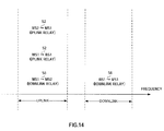
- FIG.14 is a view summarizing the usage methods of each frequency band in the communication system according to this embodiment.
- uplink relay In the case of uplink relay, transmission from relay requesting station MS2 to relay station MS1 (signal S2) is performed using uplink as in normal communication. Furthermore, transmission from relay station MS1 to base station BS1 (signal S2) is performed using uplink as in normal communication. Therefore, frequency to be used is uplink frequency in either route.
- transmission from base station BS1 to relay station MS1 (signal S6) is performed using downlink (downlink frequency) as in normal communication.
- transmission from relay station MS1 to relay requesting station MS2 (signal S6) is performed using uplink frequency, which is different from normal communication.
- mobile station apparatus 200 since the frequency band to be used is different between uplink and downlink, the normal (conventional) mobile station apparatus cannot receive transmission data of another mobile station apparatus.
- mobile station apparatus 200 since mobile station apparatus 200 according to this embodiment has a reception system for uplink frequency (uplink frequency reception RF section 202 to frequency separation section 105-2), mobile station apparatus 200 can receive transmission data from another mobile station apparatus. That is, if relay station MS1 and relay requesting station MS2 both have the configuration of mobile station apparatus 200, relay requesting station MS2 can receive relay data transmitted from relay station MS1 using uplink frequency by the reception system for uplink frequency. Therefore, as shown in FIG.14, downlink relay between mobile station apparatuses is performed using uplink frequency.
- the relay station embeds an identifier in the transmission signal so that the transmission data can be identified as the data addressed to base station BS1 or the relay requesting station.
- relay station MS1 receives data that is requested to be relayed by another station (mobile station MS2 outside the area or base station BS1), and temporarily stores the data in a buffer. Then, after waiting until the timing for transmitting the data of mobile station MS2, and, when this timing arrives, relay station MS1 frequency division multiplexes the stored relay data with the data of mobile station MS1 and transmits the frequency division multiplexed data to a relay destination station (base station BS1 or mobile station MS2).
- base station BS1 or mobile station MS2 base station BS1 or mobile station MS2.
- downlink relay between mobile stations (between the relay station and the relay requesting station) is performed using uplink frequency.
- downlink relay may be performed using downlink frequency as in normal downlink communication.
- the configuration of mobile station apparatus 200a is as shown in FIG.15.
- OFDM transmission section 119-2 and downlink frequency transmission RF section 212 are transmission systems performing downlink relay from the relay station to the relay requesting station.
- frequency separation section 105-2 separates (extracts) only relay data for another station and outputs the data to other-station data channel demodulation section 107.
- relay station MS1 may report the data relay to mobile station MS2 outside the area.
- relay station MS1 directly communicates with base station BS1, but this is by no means limiting, and relay station MS1 may communicate via another relay station between mobile station MS1 and base station BS1.
- the mobile station apparatus and communication relay method according to the present invention are not limited to the above-described embodiments and can be implemented by making various changes.
- the embodiments can be appropriately combined and implemented.
- the present invention can be implemented with software.
- the present invention can be implemented with software.
- storing this program in a memory and making an information processing section execute this program it is possible to implement the same function as the mobile station apparatus and communication terminal apparatus of the present invention.
- each function block used to explain the above-described embodiments is typically implemented as an LSI constituted by an integrated circuit. These may be individual chips or may partially or totally contained on a single chip.
- each function block is described as an LSI, but this may also be referred to as "IC”, “system LSI”, “super LSI”, “ultra LSI” depending on differing extents of integration.
- circuit integration is not limited to LSI's, and implementation using dedicated circuitry or general purpose processors is also possible.
- LSI manufacture utilization of a programmable FPGA (Field Programmable Gate Array) or a reconfigurable processor in which connections and settings of circuit cells within an LSI can be reconfigured is also possible.
- FPGA Field Programmable Gate Array
- the communication terminal apparatus and communication relay method according to the present invention have the effect of implementing communication relay of another station and suppressing increase in power consumption of the communication terminal apparatus, and can be applied to a multihop system and the like.
Landscapes
- Engineering & Computer Science (AREA)
- Signal Processing (AREA)
- Computer Networks & Wireless Communication (AREA)
- Power Engineering (AREA)
- Mobile Radio Communication Systems (AREA)
- Data Exchanges In Wide-Area Networks (AREA)
- Small-Scale Networks (AREA)
- Radio Relay Systems (AREA)
Abstract
There is provided a mobile station device in a multi-hop system capable of realizing relay of communication of another station while suppressing increase of power consumption of the local station. In this device, at timing t1, a mobile station MS2 transmits data S2 destined to a base station BS1, to a mobile station MS1. The mobile station MS1 receives the data S2 and temporarily stores it in a buffer. The mobile station MS1 waits until timing t4 when the data S1 of the mobile station MS1 is to be transmitted. When this timing has come, the data S2 stored in the buffer is multiplexed with the data S1 of the mobile station MS1 and transmitted to the base station BS1.
Description
- The present invention relates to a communication terminal apparatus and communication relay method in a multihop system adopting an OFDM (Orthogonal Frequency Division Multiplex) scheme.
- In a mobile communication system as typified by a mobile telephone or the like, with the development of multimedia information, large volume data such as still image and moving image, as well as speech data, has been processed. In the future, since it is expected that the data volume will further increase, it is actively studied to realize high transmission rate by making frequency band of a radio signal higher.
- However, since a radio signal of high frequency is largely attenuated depending on transmission distance, the radius of a cell covered by a base station becomes small, and therefore it is necessary to install more base stations. In a high population density area, sufficient cost effectiveness can be obtained if more base stations are installed, and therefore the problem cannot be exposed. However, in a low population density area, for example, it is impractical to install base stations every few hundred meters. Therefore, in a low population density area, it is desired to enable communication between base stations and communication terminals without increasing the number of base stations.
- As a means for solving this problem, there is a technology called a multihop system (or multihop network) (for example, refer to
Patent Document 1.) In this multihop system, each communication terminal has a communication relay function and relays communication between another communication terminal and a base station. Therefore, a communication terminal that is located outside the communication area (outside a cell) and cannot directly communicate with the base station (hereinafter referred to as a "relay requesting station") requests another communication terminal that can directly communicate with the base station to relay communication. Then, the communication terminal requested to relay communication (hereinafter referred to as a "relay station") establishes a link to the base station, and relays communication between the communication terminal outside the area and the base station. By this means, the communication terminal outside the area can communicate with the base station.
Patent Document 1: Japanese Patent Application Laid-Open No.HEI11-289349 - However, in the conventional multihop system, even if the subject station (relay station) does not perform communication, a circuit of the subject station is used for communication of another station outside the area (relay requesting station), and therefore, there is a problem that power consumption of the subject station increases. In particular, a communication terminal located at a cell edge (area near the boundary with a neighboring cell) has a high possibility of performing a relay for the communication terminal outside the area, and therefore power consumption increases prominently.
- It is therefore an object of the present invention to provide a communication terminal apparatus, in a multihop system, capable of relaying communication of another station and suppressing increase in power consumption of the communication terminal apparatus, and provide a communication relay method used in the communication terminal apparatus.
- A communication terminal apparatus of the present invention that relays communication between a base station and another communication terminal in a communication system of an OFDM scheme, adopts a configuration having: a storage section that stores communication data between the base station and another communication terminal; and a transmission section that frequency division multiplexes the stored communication data with data of the communication terminal apparatus and transmits the frequency division multiplexed data at a timing for transmitting the data of the communication terminal apparatus.
- A communication system of the present invention is a communication system of an OFDM scheme having a base station and a plurality of communication terminals, wherein, when a first communication terminal is requested to relay communication with the base station from a second communication terminal, the first communication terminal temporarily stores relay data and frequency division multiplexes the relay data with data of the first communication terminal, transmits the frequency division multiplexed data at a timing for transmitting the data of the first communication terminal, and reports the relay to the second communication terminal, and, when the second communication terminal receives the report of the relay from the first communication terminal, the second communication terminal reports the relay to a user of the second communication terminal.
- According to the present invention, in the multihop system, it is possible to relay communication between a communication terminal located outside the area and a base station, and suppress increase in power consumption of the communication terminal.
-
- FIG.1 illustrates a case in which a mobile station within a cell relays uplink communication between a mobile station located outside the cell and a base station;
- FIG.2A shows timings of uplink communication/downlink communication in a TDD system, FIG.2B is a view showing a transmission signal of a mobile station outside the area, and FIG.2C is a view showing a transmission signal of a relay station;
- FIG.3 shows an example of a usage state of transmission subcarriers of a relay station;
- FIG.4 shows an example of a relationship between transmission subcarriers of a mobile station outside the area and available subcarriers of a relay station;
- FIG.5 shows a relationship between the number of transmission subcarriers and power consumption;
- FIG.6 illustrates a case in which a mobile station within a cell relays downlink communication between a mobile station outside the area and a base station;
- FIG.7A shows timings of uplink communication/downlink communications in a TDD system, FIG. 7B shows a transmission signal of a base station, and FIG. 7C shows a transmission signal of a relay station;
- FIG.8 shows an example of a usage state of transmission subcarriers for a relay station;
- FIG. 9 is a block diagram showing a main configuration of a mobile station apparatus according to
Embodiment 1; - FIG.10 is a block diagram showing a main configuration of a base station apparatus according to
Embodiment 1; - FIG.11 illustrates a flow in a case in which a relay station relays data of a relay requesting station;
- FIG.12 shows an example of a usage state of transmission subcarriers for a relay station;
- FIG.13 is a block diagram showing a main configuration of a mobile station apparatus according to Embodiment 2;
- FIG.14 is a view summarizing the usage methods of each frequency band in a communication system according to Embodiment 2; and
- FIG.15 is a block diagram showing variations of a mobile station apparatus according to Embodiment 2.
- Embodiments of the present invention will be described below in detail with reference to the accompanying drawings. As an example of a communication terminal apparatus, a case will be explained where a mobile station apparatus such as a mobile telephone is used.
- One aspect of the present invention is that, in the multihop system, even when a mobile station is requested to perform a relay from another mobile station, the mobile station does not always perform the relay, and the cases of performing a relay are limited.
- Specifically, the mobile station according to
Embodiment 1 of the present invention is located in a location where direct communication with a base station is possible in the multipop system adopting an OFDM-TDD (Orthogonal Frequency Division Multiplex ― Time Division Duplex) system. When a mobile station according to this embodiment is requested to relay communication with the above-described base station from another mobile station located outside the area, the mobile station performs a relay in the following limited cases. In addition, for easy under standing, uplink communication between a mobile station outside the area and a base station is referred to as "uplink relay", downlink communication between a mobile station outside the area and the base station is referred to as "downlink relay", and uplink relay and downlink relay will be explained separately. - FIG. 1 illustrates a case in which mobile station (relay station) MS1 within a cell relays uplink communication between mobile station (relay requesting station) MS2 located outside cell A1 and base station BS1, that is, a case of uplink relay.
- In uplink, the cases in which mobile station MS1 performs relay are limited as follows. That is, at the timing when mobile station MS1 transmits data to base station BS1, mobile station MS1 relays transmission data from mobile station MS2 to base station BS1. To be more specific, mobile station MS1 transmits transmission data S2 transmitted from mobile station MS2 to base station BS1 together with transmission data S1 of mobile station MS1.
- FIG.2A to FIG.2C illustrate a timing when mobile station MS1 relays data of mobile station MS2.
- FIG.2A shows uplink communication/downlink communication timings between base station BS1 and mobile station MS1, that is, uplink communication/downlink communication timings in a TDD system. In this figure, downward arrows indicate downlink communication, and upward arrows indicate uplink communication. Furthermore, FIG.2B shows a transmission signal of mobile station MS2 outside the area (received signal of relay station MS1), and FIG.2C shows a transmission signal of relay station MS1.
- As shown in FIG.2B, mobile station MS2 transmits data S2 for base station BS1 to mobile station MS1 at downlink communication timing t1 in a cellular system (TDD system) of base station BS1. Here, although a case is described as an example in which mobile station MS2 is synchronized with a TDD system, mobile station MS2 does not necessarily have to be synchronized.
- Mobile station MS1 receives data S2 and temporarily stores data S2 in a buffer. Then, as shown in FIG.2C, after waiting until timing t4 of transmitting data S1 of mobile station MS1 comes, and at timing t4, mobile station MS1 multiplexes data S2 stored in the buffer with data S1 of mobile station MS1 and transmits the multiplexed data to base station BS1. When a waiting time of the data relay exceeds a predetermined time, mobile station MS1 discards this relay data and does not perform relay.
- Then, mobile station MS1 confirms whether or not there is an unused subcarrier in OFDM frequencies, that is, a subcarrier to which transmission data for base station BS1 of mobile station MS1 or a control channel signal is not mapped among available subcarriers when mobile station MS1 performs transmission (available subcarrier). Then, if there is an available subcarrier, mobile station MS1 determines whether the available subcarrier has enough capacity for a data relay (whether the capacity of available subcarrier is larger than the size of relay data). If there is not enough capacity for a data relay, mobile station MS1 does not perform a relay.
- FIG.3 shows an example of a usage state of transmission subcarriers for relay station MS1.
- In this example, subcarriers having center frequencies f1 to f12 are subcarriers to which transmission data of mobile station MS1 is mapped (subcarreirs for MS1), and a subcarrier of center frequency f17 is a subcarrier to which a control channel is mapped. Therefore, subcarriers having center frequencies f13 to f16 are the above-described available subcarriers.
- Then, since there are available subcarriers, mobile station MS1 confirms the capacity of these available subcarriers and relays communication between mobile station MS2 and base station BS1. To be more specific, mobile station MS1 maps data which is requested to be transmitted from mobile station MS2 to base station BS1, to the above-described available subcarriers. Here, when the frequencies of transmission subcarriers for mobile station MS2 are covered by (included in) the frequencies of available subcarriers for mobile station MS1, mobile station MS1 maps data of mobile station MS2 to subcarriers with the frequency as it is.
- Then, after mobile station MS1 multiplexes subcarriers to which data of mobile station MS2 is mapped with subcarriers to which data of mobile station MS1 is mapped and obtains a multicarrier signal, mobile station MS1 transmits this multicarrier signal to base station BS1.
- In addition, when the frequencies of transmission subcarriers for mobile station MS2 are not covered by the frequencies of available subcarriers for mobile station MS1, mobile station MS1 changes frequency as describedbelow. FIG. 4 shows an example of a relationship between transmission subcarriers for mobile station (relay requesting station) MS2 outside the area and available subcarriers for relay station MS1, that is, a case in which both subcarriers have the above relationship. Here, FIG.4A shows transmission subcarriers for mobile station (relay requesting station) MS2, and FIG.4B shows available subcarriers for relay station MS1.
- In an example of this figure, while the range of center frequencies of transmission subcarriers for mobile station MS2 outside the area is between f13 and f16, the range of center frequencies of available subcarriers for relay station MS1 is between f1 and f6. In this way, the frequencies of transmission subcarriers for a mobile station which requests a relay are not always covered (included) by the frequencies of available subcarriers for the relay station. In this case, relay station MS1 maintains (fixes) the frequencies of transmission subcarriers for relay station MS1, and shifts the frequencies of transmission subcarriers for relay data so that the frequencies of transmission subcarriers for the relay data are included within the frequency range of available subcarriers. In the example of FIG.4, the range of center frequencies of relay data subcarriers change from f13 and f16 to f1 and f6. By this means, mobile station MS1 can smoothly relay data. Furthermore, since relay station MS1 does not change the frequencies of transmission subcarriers for relay station MS1, for example, even in a communication system such as frequency scheduling in which subcarriers are assigned to use in advance to each mobile station, the frequency scheduling functions effectively.
- Next, the effects of adopting the above communication relay method will be described. FIG.5 shows a relationship between the number of transmission subcarriers for a mobile station and power consumption.
- As shown in this figure, if there is at least one transmission subcarrier (actually transmitted subcarrier), power consumption of the mobile station substantially increases compared to the case where there is no transmission subcarrier. However, when the number of transmission subcarriers further increases, increase in power consumption slows down, and, even if the number of transmission subcarriers increases, power consumption does not change substantially compared to the case where the number of transmission subcarriers is one.
- Consequently, when mobile station MS1 performs transmission--that is, when the number of transmission subcarriers is 1 or more--mobile station (relay station) MS1 according to this embodiment maps data of another station (such as mobile station MS2) to available subcarriers and transmits the subcarriers. If such transmission is performed, it can be seen from FIG.5 that power consumption of mobile station MS1 increases little. Furthermore, as described above, relay station MS1 continues mapping relay data to available subcarriers, and does not change the frequencies of transmission subcarriers for relay station MS1. That is, even if relay station MS1 has a function of relaying data, relay station MS1 transmits data of relay station MS1 as a first priority. Therefore, it can be seen that relay station MS1 is influenced little by relaying data.
- FIG.6 illustrates a case in which mobile station (relay station) MS1 within the cell relays downlink communication between mobile station (relay requesting station) MS2 outside the area and base station BS1, that is, a case of downlink relay.
- In downlink, cases in which mobile station MS1 performs relay are limited as follows. That is, at the timing when mobile station MS1 transmits data to base station BS1, mobile station MS1 relays transmission data for mobile station MS2 from base station BS1. To be more specific, mobile station MS1 transmits transmission data S6 transmitted from base station BS1 to mobile station MS2 at the same timing as the timing for transmission data S5 of mobile station MS1.
- FIGs.7A to 7C illustrate a timing when mobile station MS1 relays data of base station BS1.
- FIG.7A shows uplink communication/downlink communication timings in a TDD system. Furthermore, FIG.7B shows a transmission signal of base station BS1 (received signal at relay station MS1), and FIG.7C shows a transmission signal at relay station MS1.
- As shown in FIG.7B, at timing t11, base station BS1 transmits data S6 for mobile station MS2 to mobile station MS1. Mobile station MS1 receives this data S6 and temporarily stores data S6 in a buffer. Then, as shown in FIG. 7C, after waiting until the timing for transmitting data S5 of mobile station MS1 to base station BS1--that is, uplink communication timing t14--and at this timing t14, mobile station MS1 multiplexes relay data S6 stored in the buffer with data S5 of mobile station MS1 and transmits the multiplexed data.
- Relay data S6 is downlink relay data though transmitted at uplink communication timing t14. Therefore, mobile station MS2 receiving this relay data S6 needs to perform reception processing at an uplink communication timing.
- Furthermore, at this time, as described in uplink communication, mobile station MS1 determines whether or not there is an available subcarrier in OFDM frequencies.
- FIG.8 shows an example of a usage state of transmission subcarriers for relay station MS1.
- In this example, subcarriers for center frequencies f13 to f16 are available subcarriers (subcarriers for base station BS1). Then, mobile station MS1 maps data for mobile station MS2 from base station BS1 to the available subcarriers, and multiplexes the subcarriers with subcarriers to which data for base station BS1 frommobile station MS1 is mapped and transmits the subcarriers.
- FIG.9 is a block diagram showing a main configuration of mobile station MS1 (mobile station apparatus 100) according to this embodiment implementing the above-described operations.
- Sections of this mobile station apparatus 100 implement the following operations:
-
Antenna 101 receives a radio signal from another station (base station BS1 or another mobile station such as mobile station MS2), and transmits a radio signal from mobile station MS1.TDD switch 102 switches between transmission and reception of the radio signal in synchronization with uplink/downlink timings in the TDD system.Reception RF section 103 performs predetermined radio reception processing such as down-conversion on the radio signal received viaantenna 101, and obtains a baseband signal.OFDM reception section 104 performs predetermined OFDM reception processing such as inverse fast Fourier transform (IFFT) on the baseband signal, and obtains subcarrier signals from the multicarrier baseband signal. -
Frequency separation section 105 separates subcarrier signals by frequency (refer to FIG.3 and FIG. 8), and separates data for mobile station MS1 from data for another station. Subject-station datachannel demodulation section 106 demodulates data for mobile station MS1 and obtains received data for mobile station MS1. Other-station datachannel demodulation section 107 demodulates data for another station and temporarily stores this demodulated data inbuffer 108. - On the other hand, when transmission data is generated,
buffer 111 temporarily stores the data. - Transmission
timing determination section 112 determines a timing for transmitting data of mobile station MS1 in accordance with the uplink/downlink timing in the TDD system, reads the stored transmission data frombuffer 111 according to this timing, and outputs the transmission data to transmissionfrequency determination section 113. Furthermore, transmissiontiming determination section 112 reports the transmission timing of mobile station MS1 to buffer 108. - Transmission
frequency determination section 113 determines frequencies (subcarriers) needed to transmit this data based on the transmission data size or the like outputted from transmissiontiming determination section 112, and determines subcarriers needed to transmit a control channel. Furthermore, when there are available subcarriers as already described using FIG.3 and FIG.8, transmissionfrequency determination section 113 reports the presence of available subcarriers and information about these available subcarriers to other-station datachannel modulation section 114. Furthermore, transmissionfrequency determination section 113 reports information about the subcarriers use by mobile station MS1 and available subcarriers, to controlchannel generation section 115. - Buffer 108 outputs the stored data for another station to other-station data
channel modulation section 114 based on the transmission timing of mobile station MS1 reported from transmissiontiming determination section 112. - When the presence of available subcarriers is reported from transmission
frequency determination section 113, other-station datachannel modulation section 114 performs predetermined modulation processing such as QPSK on data for another station outputted frombuffer 108 and outputs the result tofrequency multiplex section 118. - Control
channel generation section 115 generates a control channel signal reporting the information about the subcarriers used by mobile station MS1 and available subcarriers reported from transmissionfrequency determination section 113, and outputs the control channel signal to controlchannel modulation section 116. - Control
channel modulation section 116 performs predetermined modulation processing such as QPSK on the control channel signal and outputs the result tofrequency multiplex section 118. BS datachannel modulation section 117 performs predetermined modulation processing such as QPSK on data for base station BS1 from mobile station MS1 and outputs the result tofrequency multiplex section 118. -
Frequency multiplex section 118 maps modulation signals outputted from other-station datachannel modulation section 114, controlchannel modulation section 116 and BS datachannel modulation section 117 to subcarriers determined byfrequency determination section 113, and thereby obtains the transmission signal multiplexed on the frequency axis, and outputs the transmission signal toOFDM transmission section 119. -
OFDM transmission section 119 performs predetermined OFDM transmission processing such as fast Fourier transform (FFT) on the transmission signal and obtains a multicarrier baseband signal.Transmission RF section 120 performs predetermined radio transmission processing such as up-conversion on this baseband signal and transmits the obtained radio signal viaTDD switch 102 andantenna 101. - In addition, mobile station MS1 includes an identifier of mobile station MS1 in relay data so that base station BS1 can recognize the data relay from another mobile station.
- FIG.10 is a block diagram showing a main configuration of base station BS1 (base station apparatus 150) according to this embodiment.
- Sections of this base station apparatus 150 implement the following operations:
-
Modulation section 151 performs predetermined modulation processing such as QPSK on transmission data. Transmissiontiming determination section 152 determines a transmission timing for mobile station MS1 in accordance with the uplink/downlink timing in the TDD system and reports this timing to buffer 153. Buffer 153 temporarily stores the modulation signal outputted frommodulation section 151 and outputs the stored modulation signal toOFDM transmission section 154 based on the transmission timing of mobile station MS1 reported from transmissiontiming determination section 152.OFDM transmission section 154 performs predetermined OFDM transmission processing such as fast Fourier transform on the modulation signal and obtains a multicarrier baseband signal.Transmission RF section 155 performs predetermined radio transmission processing such as up-conversion on the baseband signal and transmits the obtained radio signal viaTDD switch 156 andantenna 157. - On the other hand,
reception RF section 158 performs predetermined radio reception processing such as down-conversion on the radio signal received viaantenna 157 andTDD switch 156 and obtains a baseband signal.OFDM reception section 159 performs predetermined OFDM reception processing such as inverse fast Fourier transform on the baseband signal and obtains subcarrier signals from the multicarrier baseband signal. Controlchannel demodulation section 160 performs demodulation processing on the control channel transmitted from mobile station MS1, extracts information about the subcarriers used by mobile station MS1 (subcarriers for mobile station MS1) and available subcarriers, and outputs the information tofrequency separation section 161.Frequency separation section 161 separates subcarrier signals by frequency based on the information about the subcarriers used by mobile station MS1 and the available subcarriers, and separates signals from mobile station MS1 from signals from mobile station MS2. Data channel demodulation sections 162-1 and 162-2 perform demodulation processing on the signals frommobile station MS1 and the signals frommobile station MS2, and obtains data from mobile station MS1 and data from mobile station MS2. - In this way, according to this embodiment, in the multihop system, relay station MS1 receives data that is requested to be relayed by another station (mobile station MS2 outside the area or base station BS1), and temporarily stores the data in the buffer. Then, after waiting until the timing for transmitting data of mobile station MS1, and, when this timing arrives, relay station MS1 frequency division multiplexes the stored relay data with the data of mobile station MS1, and transmits the frequency division multiplexed data to the relay destination station (base station BS1 or mobile station MS2). By this means, it is possible to relay communication of another station and suppress increase in power consumption of mobile station MS1.
- Furthermore, in the above configuration, relay station MS1 judges whether or not there is a subcarrier that is not used by mobile station MS1 (available subcarrier) in OFDM frequencies, and maps relay data to this available subcarrier. By this means, without sacrificing data transmission of mobile station MS1, data relay of another station can be implemented.
- In addition, when data relay is carried out, relay station MS1 may report the relay to mobile station MS2 outside the area. By this means, the following effects can be recognized.
- Generally, since the mobile station constantly monitors the reception level of pilot signals transmitted from the base station, a user of the mobile station can judge whether or not the user is located within a cell. Therefore, though the user of mobile station MS2 according to this embodiment recognizes that the user is located outside the cell, the user tries to transmit data to base station BS1. In this situation, the user of mobile station MS2 may want to confirm whether or not data transmission is possible (or was possible). As a method for telling this user whether or not data transmission is possible, it is considered that mobile station MS2 searches for a relay station before data transmission, holds the relay station, and transmits data to this relay station. In this case, mobile station MS2 performs communication after holding the relay station, thereby naturally judging that data transmission is possible. However, in this method, processing of searching for a relay station and holding this relay station requires signaling (exchanging control signals) with this relay station, and since this signaling is different from usual communication processing in the case in which the mobile station is located within the cell, a new signaling circuit is required. On the other hand, as described above, if relay station MS1 reports the data relay to mobile station MS2 when data relay is carried out, mobile station MS2 can judge that data transmission is possible with a simple configuration without signaling in advance. Then, by displaying the success of data transmission on a display or the like, this fact can be reported to the user of mobilestation MS1. Furthermore, since relay station MS1 can report to mobile station MS2 outside the area simultaneously upon data transmission to base station BS1, transmission power does not increase markedly. Further, a signal transmitted by relay station MS1 to base station BS1 can be received by mobile station MS2, except for a case in which directivity is added and transmitted. Therefore, if this signal is used as the above-described report signal, relay station MS1 does not need to separately transmit a report signal to mobile station MS2.
- Furthermore, in this embodiment, although a case has been described as an example in which relay station MS1 directly communicates with base station BS1, this is by no means limiting, and communication may be performed via another relay station between mobile station MS1 and base station BS1.
- Furthermore, in this embodiment, although a case has been described as an example in which a relay station is one of mobile station MS1--that is, there is one communication route (relay route) of relay data--, there may be a plurality of relay routes. For example, two mobile stations--mobile station MS1 and mobile station MS1'--may relay data of mobile station MS2 outside the area. Then, if timings for transmitting relay data of two relay stations (uplink timings in the TDD system) are the same, from the viewpoint of base station BS1, data of mobile station MS2 outside the area seems to arrive through two communication paths, and the situation is practically equivalent to the situation of communication under the multipath environment. Furthermore, if transmission timings of two relay stations are different, from the viewpoint of base station BS1, the situation is practically equivalent to the situation in which mobile station MS2 retransmits data.
- Furthermore, here, although a case has been described as an example in which data from mobile station MS2 located outside the cellular system is relayed, this is by no means limiting, and data from a mobile station that cannot receive a signal from base station BS1 located within the cell (mobile station located in a dead area), may be relayed. That is, the present invention is effective for measures against the dead area.
- Furthermore, in an example of FIG.3 and FIG.8, although a case has been described as an example in which available subcarriers of the relay station are successive on the frequency axis, available subcarriers may be distributed unsuccessively and discretely.
- Furthermore, in this embodiment, although a case has been described as an example inwhich, when the capacity of available subcarriers is insufficient for a data relay, mobile station MS1 does not perform a relay, mobile station MS1 may relay only part of data. Specifically, mobile station MS2 located outside the area assigns priorities in advance to data to be transmitted to base station BS1 based on data accuracy or the like. Then, mobile station MS2 transmits this data with priorities to relay station MS1. Relay station MS1 maps data in the order of descending priorities out of the received data to available subcarriers of relay station MS1, and at the stage at which mapping of all relay data is completed or available subcarriers are all filled, multiplexes the data with the data of relay station MS1 and transmits the multiplexed data to base station BS1. By this means, even when the size of the relay data is larger than the capacity of available subcarriers, data is selected in the order of descending priorities and relayed to base station BS1. Therefore, at base station BS1, although data accuracy is poor, a state can be maintained that is meaningful for communication (communication can be practically established.)
- In
Embodiment 1, a case has been described as an example in which the present invention is applied to an OFDM-TDD system, but in Embodiment 2, a case will be described in which the present invention is applied to an OFDM-FDD (Orthogonal Frequency Division Multiplex ― Frequency Division Duplex) system. In the TDD system described inEmbodiment 1, since the same frequency band is used in uplink relay and downlink relay, the relay station does not need to switch the frequencies to be used according to uplink or downlink. However, in the FDD system described in this embodiment, as the frequency band to be used is different between uplink and downlink, the configuration of the relay station substantially differs fromEmbodiment 1. The configuration of the relay station will be described later in detail. - FIG.11A and FIG.11B illustrate a flow of a case in which relay station MS1 relays data of relay requesting station MS2. In addition, the assumed situation is the same as in FIG.1, and mobile station MS1 within the cell relays uplink communication between mobile station MS2 located outside cell A1 and base station BS1. Signals are assigned the same reference numerals as in FIG.1.
- Relay station MS1 receives transmission signal S2 in the uplink frequency from relay requesting station MS2 at an arbitrary timing. Then, relay station MS1 temporarily stores the received signal in a buffer, and, at the timing of data transmission to base station BS1 of relay station MS1, by mapping data S2 from relay requesting station MS2 to available subcarrier, multiplexes data S1 of relay station MS1 with relay data S2 and transmits the multiplexed data. The timing at which relay station MS1 transmits relay data S2 to base station BS1 is irregular, and the time interval from relay station MS1 receiving relay data S2 to transmitting this data to base station BS1 is also irregular. Therefore, when a predetermined time passes while waiting for transmission of relay data S2, relay station MS1 cancels relay and discards relay data S2.
- FIG.12 is a view showing an example of a usage state of transmission subcarriers for relay station MS1.
- Subcarriers of center frequencies f13 to f16 are used in transmission from relay station MS1 to base station BS1--that is, transmission of the data of relay station MS1--and the subcarriers of center frequencies f1 to f12 are available subcarriers. Then, relay station MS1 maps signal S2 received from relay requesting station MS2 to available subcarriers (center frequencies f1 to f12), and performs relay transmission to base station BS1.
- In addition, relay data may be mapped to any subcarrier if a subcarrier is an available subcarrier, and, for example, when a successive plurality of subcarriers can be held as available subcarriers, relay data is mapped to these subcarriers. Furthermore, when available subcarriers are located separately one another--that is, located discretely--relay data is mapped discretely.
- In addition, in FIG. 11 and FIG. 12, a case of uplink relay has been described as an example, but the present invention can be implemented by the same relay method in the case of downlink relay. Since this has been described in
Embodiment 1, the explanation is omitted here. - FIG.13 is a block diagram showing a main configuration of mobile station apparatus 200 according to this embodiment implementing the above-described operations. In addition, since mobile station apparatus 200 has the same configuration as mobile station apparatus 100 (refer to FIG. 9) described in
Embodiment 1, components basically performing the same operation are assigned the same reference numerals without further explanations. Furthermore, a plurality of components with the same configuration are indicated with branch numerals as signed after reference numerals. - One of the features of mobile station apparatus 200 is to have a function of receiving relay data for another station (for example, uplink frequency
reception RF section 202, OFDM reception section 104-2 and frequency separation section 105-2) in addition to a normal reception function. - Function of each section of mobile station apparatus 200 will be described below.
- Downlink frequency
reception RF section 201 performs predetermined radio reception processing such as down-conversion on a downlink radio signal from base station BS1 received viaantenna 101, that is, a radio signal of downlink frequency, and obtains a baseband signal. Data included in the radio signal of downlink frequency is normal communication data for mobile station MS2, or relay data for another station. - Uplink frequency
reception RF section 202 performs predetermined radio reception processing such as down-conversion on a signal such as relay data from another station (for example, MS2) received viaantenna 101--that is, a radio signal of uplink frequency--and obtains a baseband signal. Data included in the radio signal of uplink frequency is, as shown in FIG.11 and FIG.12, relay data of uplink relay for base station BS1 from another station. There is also a case in which, as described below, mobile station MS2 is a relay requesting station located outside the cell, and data is relay data of downlink relay transmitted from a relay station for mobile station MS2. Downlink relay will be described later in detail. - There are two
OFDM reception sections 104 for downlink frequency and for uplink frequency (104-1 and 104-2). Furthermore, there are twofrequency separation sections 105 for downlink frequency and for uplink frequency (105-1 and 105-2). - Subject-station data
channel demodulation section 106 demodulates data for mobile station MS2 outputted from OFDM reception section 104-1 or OFDM reception section 104-2, and obtains data for mobile station MS2. Other-station datachannel demodulation section 107 demodulates data for another station outputted from OFDM reception section 104-1 or OFDM reception section 104-2, and temporarily stores this demodulated data inbuffer 108. - On the other hand, uplink frequency
transmission RF section 211 performs predetermined radio transmission processing such as up-conversion on the baseband signal outputted fromOFDM transmission section 119 and transmits the obtained radio signal of uplink frequency viaantenna 101. Data included in the radio signal of uplink frequency is normal communication data to base station BS1 of mobile station MS2, or, as described below, relay data of uplink relay and downlink relay. - FIG.14 is a view summarizing the usage methods of each frequency band in the communication system according to this embodiment.
- A case of uplink relay already described in FIG.11 and FIG.12 will be described.
- In the case of uplink relay, transmission from relay requesting station MS2 to relay station MS1 (signal S2) is performed using uplink as in normal communication. Furthermore, transmission from relay station MS1 to base station BS1 (signal S2) is performed using uplink as in normal communication. Therefore, frequency to be used is uplink frequency in either route.
- Next, a case of downlink relay will be described.
- In the case of downlink relay, transmission from base station BS1 to relay station MS1 (signal S6) is performed using downlink (downlink frequency) as in normal communication. However, transmission from relay station MS1 to relay requesting station MS2 (signal S6) is performed using uplink frequency, which is different from normal communication.
- As already described, in the FDD system, since the frequency band to be used is different between uplink and downlink, the normal (conventional) mobile station apparatus cannot receive transmission data of another mobile station apparatus. However, as shown in FIG.13, since mobile station apparatus 200 according to this embodiment has a reception system for uplink frequency (uplink frequency
reception RF section 202 to frequency separation section 105-2), mobile station apparatus 200 can receive transmission data from another mobile station apparatus. That is, if relay station MS1 and relay requesting station MS2 both have the configuration of mobile station apparatus 200, relay requesting station MS2 can receive relay data transmitted from relay station MS1 using uplink frequency by the reception system for uplink frequency. Therefore, as shown in FIG.14, downlink relay between mobile station apparatuses is performed using uplink frequency. - In addition, the relay station embeds an identifier in the transmission signal so that the transmission data can be identified as the data addressed to base station BS1 or the relay requesting station.
- In this way, according to this embodiment, in the multihop system, relay station MS1 receives data that is requested to be relayed by another station (mobile station MS2 outside the area or base station BS1), and temporarily stores the data in a buffer. Then, after waiting until the timing for transmitting the data of mobile station MS2, and, when this timing arrives, relay station MS1 frequency division multiplexes the stored relay data with the data of mobile station MS1 and transmits the frequency division multiplexed data to a relay destination station (base station BS1 or mobile station MS2). By this means, it is possible to implement communication relay of another station and suppress increase in power consumption of mobile station MS1. That is, since the relay station relays a signal of the relay requesting station only in the case in which there is a transmission signal of the relay station, it is possible to suppress power consumption.
- In addition, in this embodiment, a case has been described as an example in which downlink relay between mobile stations (between the relay station and the relay requesting station) is performed using uplink frequency. However, downlink relay may be performed using downlink frequency as in normal downlink communication. In this case, the configuration of mobile station apparatus 200a is as shown in FIG.15. OFDM transmission section 119-2 and downlink frequency
transmission RF section 212 are transmission systems performing downlink relay from the relay station to the relay requesting station. In this case, since there is no data for the mobile station in the radio signal of uplink frequency, frequency separation section 105-2 separates (extracts) only relay data for another station and outputs the data to other-station datachannel demodulation section 107. - Furthermore, when relay station MS1 carries out data relay, relay station MS1 may report the data relay to mobile station MS2 outside the area.
- Furthermore, in this embodiment, a case has been described as an example in which relay station MS1 directly communicates with base station BS1, but this is by no means limiting, and relay station MS1 may communicate via another relay station between mobile station MS1 and base station BS1.
- Further, in this embodiment, a case has been described as an example in which there is one relay route, but there may be a plurality of relay routes.
- Still further, in this embodiment, a case has been described as an example in which data from mobile station MS2 located outside the cellular system is relayed, but data from a mobile station located in a dead area may be relayed.
- The embodiments of the present invention have been described.
- The mobile station apparatus and communication relay method according to the present invention are not limited to the above-described embodiments and can be implemented by making various changes. For example, the embodiments can be appropriately combined and implemented.
- In addition, in the above-described embodiments, although cases have been described as an example in which a mobile station apparatus such as a mobile telephone is used as a relay station or a relay requesting station, other communication terminals, for example, a PDA (Personal Digital Assistant) or a laptop computer can be used.
- Furthermore, although a case has been described as an example in which the present invention is implemented with hardware, the present invention can be implemented with software. For example, by describing the communication relay method algorithm according to the present invention in a programming language, storing this program in a memory and making an information processing section execute this program, it is possible to implement the same function as the mobile station apparatus and communication terminal apparatus of the present invention.
- Furthermore, each function block used to explain the above-described embodiments is typically implemented as an LSI constituted by an integrated circuit. These may be individual chips or may partially or totally contained on a single chip.
- Furthermore, here, each function block is described as an LSI, but this may also be referred to as "IC", "system LSI", "super LSI", "ultra LSI" depending on differing extents of integration.
- Further, the method of circuit integration is not limited to LSI's, and implementation using dedicated circuitry or general purpose processors is also possible. After LSI manufacture, utilization of a programmable FPGA (Field Programmable Gate Array) or a reconfigurable processor in which connections and settings of circuit cells within an LSI can be reconfigured is also possible.
- Further, if integrated circuit technology comes out to replace LSI's as a result of the development of semiconductor technology or a derivative other technology, it is naturally also possible to carry out function block integration using this technology. Application in biotechnology is also possible.
- The present application is based on
Japanese Patent Application No.2004-068793 Japanese Patent Application No.2005-56381 - The communication terminal apparatus and communication relay method according to the present invention have the effect of implementing communication relay of another station and suppressing increase in power consumption of the communication terminal apparatus, and can be applied to a multihop system and the like.
Claims (9)
- A communication terminal apparatus that relays communication between a base station and another communication terminal in a communication system of an OFDM (Orthogonal Frequency Division Multiplex) scheme, said communication terminal apparatus comprising:a storage section that stores communication data between the base station and the another communication terminal; anda transmission section that frequency division multiplexes the stored communication data with data of the communication terminal apparatus and transmits the frequency division multiplexed data at a timing for transmitting the data of the communication terminal apparatus.
- The communication terminal apparatus according to claim 1, wherein said transmission section maps the stored communication data to an available subcarrier to which the data of the communication terminal apparatus is not mapped among subcarriers that the communication terminal apparatus can use, and performs the frequency division multiplexing.
- The communication terminal apparatus according to claim 1, further comprising a reporting section that reports to the base station that requests to relay the communication data or the another communication terminal that said transmission section transmits communication data between the base station and the another communication terminal.
- A communication terminal apparatus that communicates with a base station via a relay of another communication terminal in a communication system of an OFDM-TDD (Orthogonal Frequency Division Multiplex - Time Division Duplex) scheme, wherein said communication terminal apparatus performs reception processing at a timing for uplink communication for the communication system.
- The communication terminal apparatus according to claim 1, wherein said communication system is a communication system of an OFDM-FDD (Orthogonal Frequency Division Multiplex - Frequency Division Duplex),
further comprising a reception system that performs reception processing in uplink frequency, wherein
said communication terminal apparatus transmits the stored data to the another communication terminal in uplink frequency. - A communication terminal apparatus that communicates with a base station via a relay of another communication terminal in a communication system of an OFDM-FDD (Orthogonal Frequency Division Multiplex ― Frequency Division Duplex) scheme, said communication terminal apparatus comprising a reception system that performs reception processing in uplink frequency,
wherein said communication terminal apparatus transmits data of the communication terminal apparatus to the another communication terminal in uplink frequency. - A communication relay method that is used at a communication terminal relaying communication between a base station and another communication terminal in a communication system of an OFDM scheme, said communication relay method comprising:a storage step of storing communication data between the base station and the another communication terminal in a buffer;a multiplexing step of frequency division multiplexing the stored communication data with data of the communication terminal; anda transmission step of transmitting the frequency division multiplexed data at a timing for transmitting data of the communication terminal.
- A communication system that is a communication system of an OFDM scheme comprising a base station and a plurality of communication terminals, wherein:when a first communication terminal is requested to relay communication with the base station from a second communication terminal, the first communication terminal temporarily stores relay data and frequency division multiplexes the relay data with data of the first communicationterminal, transmits the frequency division multiplexed data at a timing for transmitting the data of the first communication terminal, and reports the relay to the second communication terminal; andwhen the second communication terminal receives the report of the relay from the first communication terminal, the second communication terminal reports the relay to a user of the second communication terminal.
- A communication apparatus that relays communication between a first communication apparatus and a second communication apparatus in a communication system of an OFDM scheme, said communication apparatus comprising:a storage section that stores communication data between the first communication apparatus and the second communication apparatus; anda transmission section that frequency division multiplexes the stored communication data with data of the communication apparatus and transmits the multiplexed data at a timing for transmitting the data of the communication apparatus.
Applications Claiming Priority (3)
| Application Number | Priority Date | Filing Date | Title |
|---|---|---|---|
| JP2004068793 | 2004-03-11 | ||
| JP2005056381A JP4652846B2 (en) | 2004-03-11 | 2005-03-01 | Communication terminal device and communication relay method |
| PCT/JP2005/004000 WO2005088867A1 (en) | 2004-03-11 | 2005-03-08 | Communication terminal device and communication relay method |
Publications (1)
| Publication Number | Publication Date |
|---|---|
| EP1710930A1 true EP1710930A1 (en) | 2006-10-11 |
Family
ID=34975944
Family Applications (1)
| Application Number | Title | Priority Date | Filing Date |
|---|---|---|---|
| EP05720272A Withdrawn EP1710930A1 (en) | 2004-03-11 | 2005-03-08 | Communication terminal device and communication relay method |
Country Status (7)
| Country | Link |
|---|---|
| US (2) | US7505735B2 (en) |
| EP (1) | EP1710930A1 (en) |
| JP (1) | JP4652846B2 (en) |
| KR (1) | KR20060124751A (en) |
| BR (1) | BRPI0508548A (en) |
| RU (1) | RU2377727C2 (en) |
| WO (1) | WO2005088867A1 (en) |
Cited By (4)
| Publication number | Priority date | Publication date | Assignee | Title |
|---|---|---|---|---|
| WO2008024938A3 (en) * | 2006-08-23 | 2008-08-21 | Qualcomm Inc | Acquisition in frequency division multiple access systems |
| WO2009110628A1 (en) * | 2008-03-06 | 2009-09-11 | Nec Corporation | Relay communication system |
| WO2013010014A1 (en) * | 2011-07-12 | 2013-01-17 | Qualcomm Incorporated | Beacons for user equipment relays |
| EP2003920A4 (en) * | 2006-03-31 | 2013-02-20 | Kddi Corp | INFORMATION TRANSMITTER, INFORMATION SENDING DEVICE, AND INFORMATION TRANSMITTING METHOD |
Families Citing this family (34)
| Publication number | Priority date | Publication date | Assignee | Title |
|---|---|---|---|---|
| US8228759B2 (en) | 2003-11-21 | 2012-07-24 | Fairfield Industries Incorporated | System for transmission of seismic data |
| US7124028B2 (en) | 2003-11-21 | 2006-10-17 | Fairfield Industries, Inc. | Method and system for transmission of seismic data |
| KR100780803B1 (en) * | 2006-06-19 | 2007-11-30 | (주)스페이스링크 | Up and Down Link Asymmetric Relay Communication System |
| JP5034369B2 (en) * | 2006-08-18 | 2012-09-26 | 富士通株式会社 | Wireless communication control method |
| EP2080309B1 (en) * | 2006-11-01 | 2017-01-11 | Nokia Solutions and Networks GmbH & Co. KG | Hierarchichal frame structure for ofdma system with relay |
| US7990906B2 (en) | 2006-11-03 | 2011-08-02 | Fujitsu Semiconductor Limited | Frame structure for a relay station operating in mobile networks |
| TWI333342B (en) * | 2006-11-06 | 2010-11-11 | Inst Information Industry | Signal relay apparatus, method, application program, and computer readable medium capable of adjusting amplifying gain dynamicaaly |
| WO2008105074A1 (en) * | 2007-02-27 | 2008-09-04 | Panasonic Corporation | Wireless relay system and relay device |
| US9264907B2 (en) * | 2007-07-10 | 2016-02-16 | Qualcomm Incorporated | Method and apparatus for interference management between networks sharing a frequency spectrum |
| WO2009031320A1 (en) * | 2007-09-07 | 2009-03-12 | Panasonic Corporation | Wireless communication device and transmission method |
| BRPI0818038A2 (en) * | 2007-10-15 | 2015-03-24 | Panasonic Corp | Radio Communication Device, Support Device, and Transmission Method |
| JP5067621B2 (en) * | 2007-10-17 | 2012-11-07 | Necカシオモバイルコミュニケーションズ株式会社 | Communication terminal device and program |
| CN101488801A (en) * | 2008-01-17 | 2009-07-22 | 株式会社Ntt都科摩 | Multicarrier radio communication system, base station, radio relay station, mobile station, and multicarrier radio communication method |
| JP4666003B2 (en) * | 2008-05-23 | 2011-04-06 | ソニー株式会社 | COMMUNICATION DEVICE, COMMUNICATION SYSTEM, COMMUNICATION METHOD, AND PROGRAM |
| US8958371B2 (en) * | 2008-09-12 | 2015-02-17 | Qualcomm Incorporated | Interference management for different wireless communication technologies |
| CN101730115B (en) * | 2008-10-24 | 2013-01-30 | 华为技术有限公司 | Method and device for relay transmission |
| RU2486711C2 (en) * | 2008-11-07 | 2013-06-27 | Хуавэй Текнолоджиз Ко., Лтд. | Relay transmission method and network node |
| US8886113B2 (en) * | 2008-12-30 | 2014-11-11 | Qualcomm Incorporated | Centralized control of relay operation |
| JP5342294B2 (en) * | 2009-03-26 | 2013-11-13 | 京セラ株式会社 | Radio relay station and radio relay method |
| US9520969B2 (en) * | 2010-01-08 | 2016-12-13 | Ntt Docomo, Inc. | Mobile communication system, radio base station, and mobile station |
| EP2538581B1 (en) | 2010-02-16 | 2019-06-26 | Electronics And Telecommunications Research Institute | Method and apparatus for broadband wireless local area communication which use a relay in transceiving operation |
| EP2454911B1 (en) | 2010-06-28 | 2014-09-10 | NEC Europe Ltd. | Method for operating a wireless terminal as an access point and wireless terminal |
| US8660057B2 (en) | 2010-08-26 | 2014-02-25 | Golba, Llc | Method and system for distributed communication |
| US20120057651A1 (en) * | 2010-09-08 | 2012-03-08 | Electronics And Telecommunications Research Institute | Transmission apparatus and method |
| JP5601211B2 (en) * | 2011-01-14 | 2014-10-08 | 富士通株式会社 | Wireless communication system, wireless access station, and communication method |
| US8611813B1 (en) * | 2011-07-22 | 2013-12-17 | Cellco Partnership | Utilizing a mobile device to control operation of a repeater |
| AU2011378436B2 (en) | 2011-10-07 | 2015-12-17 | Intel Corporation | Methods and arrangements for communications in low power wireless networks |
| JP5793090B2 (en) * | 2012-01-06 | 2015-10-14 | 株式会社Kddi研究所 | Portable relay device, packet transmission method, and packet transmission program |
| US9019841B2 (en) * | 2012-10-19 | 2015-04-28 | Qualcomm Incorporated | Architecture for relays in LTE using D2D |
| EP3125643B1 (en) * | 2015-07-31 | 2019-04-03 | Panasonic Intellectual Property Corporation of America | Improved scheduling mechanism for prose relays serving remote ues |
| JP7088022B2 (en) * | 2016-11-21 | 2022-06-21 | ソニーグループ株式会社 | Communication terminals, communication methods, programs and wireless systems |
| JP6637910B2 (en) * | 2017-01-10 | 2020-01-29 | ソフトバンク株式会社 | Moving cell base station and mobile |
| US12580670B2 (en) * | 2022-01-19 | 2026-03-17 | Ntt, Inc. | Wireless communication system, wireless communication method, and wireless device |
| US12273789B2 (en) * | 2022-06-21 | 2025-04-08 | Qualcomm Incorporated | Measurement of sounding reference signal via uplink relay |
Family Cites Families (107)
| Publication number | Priority date | Publication date | Assignee | Title |
|---|---|---|---|---|
| US5046006A (en) * | 1989-02-28 | 1991-09-03 | Raoul D. Revord | Mutual missile control system |
| US5280541A (en) * | 1991-10-24 | 1994-01-18 | Motorola, Inc. | Cordless telephone communication system link re-establishment protocol |
| JP3165218B2 (en) * | 1992-03-13 | 2001-05-14 | 株式会社日立製作所 | Personal communication system |
| US5343512A (en) * | 1992-03-27 | 1994-08-30 | Motorola, Inc. | Call setup method for use with a network having mobile end users |
| US5382958A (en) * | 1992-12-17 | 1995-01-17 | Motorola, Inc. | Time transfer position location method and apparatus |
| FR2701178A1 (en) * | 1993-02-03 | 1994-08-05 | Philips Electronique Lab | Spread spectrum communication system with multiple users. |
| JPH07162935A (en) * | 1993-12-08 | 1995-06-23 | Hitachi Ltd | Mobile communication system and mobile communication terminal device used therefor |
| JP2981394B2 (en) | 1994-02-05 | 1999-11-22 | 株式会社ケンウッド | Wireless communication equipment |
| AU706160B2 (en) * | 1994-06-08 | 1999-06-10 | Hughes Electronics Corporation | Apparatus and method for hybrid network access |
| US20010055320A1 (en) * | 1994-12-15 | 2001-12-27 | Pierzga Wayne Francis | Multiplex communication |
| US5561664A (en) * | 1995-05-11 | 1996-10-01 | Motorola, Inc. | Method of reducing audio delays associated with mobile-to-mobile communications |
| JP2671866B2 (en) * | 1995-05-25 | 1997-11-05 | 日本電気株式会社 | Path route search method in time division multiplexer network and time division multiplexer applied to the method |
| JPH0955761A (en) * | 1995-08-11 | 1997-02-25 | Toshiba Corp | Multiplex network connection device |
| US7088990B1 (en) * | 1996-02-26 | 2006-08-08 | Nokia Mobile Phones, Ltd. | Communication network terminal supporting a plurality of applications |
| US5883884A (en) * | 1996-04-22 | 1999-03-16 | Roger F. Atkinson | Wireless digital communication system having hierarchical wireless repeaters with autonomous hand-off |
| US5864578A (en) * | 1996-04-29 | 1999-01-26 | Golden Bridge Technology, Inc. | Matched filter-based handoff method and apparatus |
| FI104142B1 (en) * | 1996-10-25 | 1999-11-15 | Nokia Mobile Phones Ltd | Control method for the use of radio resources |
| JPH10190497A (en) * | 1996-12-27 | 1998-07-21 | Fujitsu Ltd | SIR measurement device |
| JP3257485B2 (en) * | 1997-11-19 | 2002-02-18 | 三菱マテリアル株式会社 | Communication system and communication method |
| JP3927714B2 (en) * | 1997-12-31 | 2007-06-13 | ユーティースターコム コリア リミテッド | Traffic control method for providing anticipatory / guaranteed services |
| DE19800378A1 (en) * | 1998-01-08 | 1999-07-15 | Cit Alcatel | Method for transferring operating parameters from a control center to a localized wireless telecommunication system and corresponding wireless telecommunication system |
| US6618368B1 (en) * | 1998-02-19 | 2003-09-09 | Hitachi, Ltd. | Data gateway and method for relaying data |
| JPH11289349A (en) | 1998-04-02 | 1999-10-19 | Nippon Telegr & Teleph Corp <Ntt> | Data packet transfer method in ad hoc network |
| US6633901B1 (en) * | 1998-10-23 | 2003-10-14 | Pss Systems, Inc. | Multi-route client-server architecture |
| JP2000165937A (en) | 1998-11-24 | 2000-06-16 | Hitachi Ltd | Wireless relay device and wireless relay method |
| US7133352B1 (en) * | 1999-09-20 | 2006-11-07 | Zion Hadad | Bi-directional communication channel |
| US6717930B1 (en) * | 2000-05-22 | 2004-04-06 | Interdigital Technology Corporation | Cell search procedure for time division duplex communication systems using code division multiple access |
| JP2001053699A (en) * | 1999-08-11 | 2001-02-23 | Hitachi Ltd | Digital broadcasting system, mobile terminal and information service station |
| JP2001077835A (en) * | 1999-08-31 | 2001-03-23 | Sony Corp | Information communication method and device |
| JP4122646B2 (en) | 1999-09-07 | 2008-07-23 | オムロン株式会社 | Meter reading transmission method, meter reading transmission system and meter reading transmitter |
| DE19950005A1 (en) * | 1999-10-18 | 2001-04-19 | Bernhard Walke | Range enhancement operating method for mobile radio communications base station uses mobile stations within normal range as relay stations for reaching mobile stations outside normal operating range |
| JP2001148702A (en) | 1999-11-22 | 2001-05-29 | Denso Corp | Data communication system |
| JP3631208B2 (en) * | 1999-12-28 | 2005-03-23 | 株式会社エヌ・ティ・ティ・ドコモ | Radio communication method and radio station |
| US6907020B2 (en) * | 2000-01-20 | 2005-06-14 | Nortel Networks Limited | Frame structures supporting voice or streaming communications with high speed data communications in wireless access networks |
| FI109953B (en) * | 2000-02-17 | 2002-10-31 | Nokia Corp | Handling connections in a mobile network |
| US6912247B2 (en) * | 2000-03-23 | 2005-06-28 | Hitachi Kokusai Electric Inc. | Digital signal transmission system and method of displaying transmission condition in digital signal transmission system |
| JP2001358766A (en) * | 2000-06-14 | 2001-12-26 | Mitsubishi Electric Corp | Packet communication system, packet communication method, and computer-readable recording medium storing a program for causing a computer to execute the method |
| US6961757B2 (en) * | 2000-08-28 | 2005-11-01 | Matsushita Electric Inducstrial Co., Ltd. | System and method for delivering e-mail data to a terminal via a relay center by multiplexing and broadcasting e-mail data with broadcasting program data |
| JP3936834B2 (en) * | 2000-09-11 | 2007-06-27 | 株式会社日立製作所 | Subscriber radio access system and apparatus used therefor |
| US7095754B2 (en) * | 2000-11-03 | 2006-08-22 | At&T Corp. | Tiered contention multiple access (TCMA): a method for priority-based shared channel access |
| GB2369532A (en) * | 2000-11-28 | 2002-05-29 | Stephen Anthony Gerar Chandler | Routing algorithm for distributed telecommunication networks |
| US7002934B2 (en) * | 2001-01-22 | 2006-02-21 | Unique Broadband Systems, Inc. | OFDM multiple upstream receiver network |
| JP2002271241A (en) * | 2001-03-06 | 2002-09-20 | Matsushita Electric Ind Co Ltd | Relay device |
| US7031293B1 (en) * | 2001-03-26 | 2006-04-18 | Tropos Networks, Inc. | Method and system to provide increased data throughput in a wireless multi-hop network |
| GB0108056D0 (en) * | 2001-03-30 | 2001-05-23 | British Telecomm | A communications system |
| US20020176485A1 (en) * | 2001-04-03 | 2002-11-28 | Hudson John E. | Multi-cast communication system and method of estimating channel impulse responses therein |
| ATE350868T1 (en) * | 2001-05-10 | 2007-01-15 | Nortel Networks Ltd | SYSTEM AND METHOD FOR DIRECTING COMMUNICATIONS BETWEEN MOBILE TELECOMMUNICATIONS NETWORKS USING DIFFERENT RADIO ACCESS TECHNOLOGIES |
| US7203508B2 (en) * | 2001-06-13 | 2007-04-10 | Ntt Docomo, Inc. | Mobile communication systems, mobile communication methods, base stations, mobile stations, and signal transmission methods in the mobile communication systems |
| EP1400062A2 (en) * | 2001-06-28 | 2004-03-24 | King's College London | Electronic data communication system |
| US20030039317A1 (en) * | 2001-08-21 | 2003-02-27 | Taylor Douglas Hamilton | Method and apparatus for constructing a sub-carrier map |
| DE10145759B4 (en) * | 2001-09-17 | 2004-02-12 | Siemens Ag | Method and radio communication system for data transmission |
| US6804738B2 (en) * | 2001-10-12 | 2004-10-12 | Sonics, Inc. | Method and apparatus for scheduling a resource to meet quality-of-service restrictions |
| US7069011B2 (en) * | 2001-11-13 | 2006-06-27 | Samsung Electronics Co., Ltd. | System and method for reliable acknowledgment between a mobile station and a base station in a wireless network |
| US6640087B2 (en) * | 2001-12-12 | 2003-10-28 | Motorola, Inc. | Method and apparatus for increasing service efficacy in an ad-hoc mesh network |
| US7180875B1 (en) * | 2001-12-20 | 2007-02-20 | Meshnetworks, Inc. | System and method for performing macro-diversity selection and distribution of routes for routing data packets in Ad-Hoc networks |
| US7363003B2 (en) * | 2001-12-21 | 2008-04-22 | Hitachi, Ltd. | Mobile communication network using mobile station with relay-function and method for rewarding relay activities of mobile station |
| CA2415132C (en) * | 2001-12-28 | 2007-07-03 | Ntt Docomo, Inc. | Radio communication system, base station, relay station, mobile station, and packet transmission control method |
| JP4052835B2 (en) * | 2001-12-28 | 2008-02-27 | 株式会社日立製作所 | Wireless transmission system for multipoint relay and wireless device used therefor |
| GB0200237D0 (en) * | 2002-01-07 | 2002-02-20 | Imec Inter Uni Micro Electr | Wireless cellular network architecture |
| JP2003234717A (en) | 2002-02-07 | 2003-08-22 | Hitachi Kokusai Electric Inc | Multi-stage relay transmission system |
| US20030153264A1 (en) * | 2002-02-11 | 2003-08-14 | Docomo Communications Laboratories Usa, Inc. | Apparatus and method for obtaining song information about a song from publicly broadcasted information |
| JP3693025B2 (en) * | 2002-02-21 | 2005-09-07 | ソニー株式会社 | Wireless communication method, wireless communication system, wireless base station, wireless communication terminal, program, and medium |
| US20030161326A1 (en) * | 2002-02-25 | 2003-08-28 | Pazhyannur Rajesh S. | Method and apparatus for data transmission |
| JP4014893B2 (en) * | 2002-03-01 | 2007-11-28 | 株式会社エヌ・ティ・ティ・ドコモ | Wireless communication system for multi-hop connection, wireless communication method, and wireless station used therefor |
| JP2003264498A (en) * | 2002-03-11 | 2003-09-19 | Hitachi Kokusai Electric Inc | Wireless communication system |
| US7043263B2 (en) * | 2002-04-11 | 2006-05-09 | Kyocera Wireless Corp. | System and method for mobile configuration |
| US7099695B1 (en) * | 2002-05-24 | 2006-08-29 | Sprint Spectrum L.P. | Method and system of selecting antennas and equipment for use within a wireless communication system |
| EP1526658B1 (en) * | 2002-06-06 | 2008-02-13 | NTT DoCoMo, Inc. | Packet communication system, packet communication method, base station, mobile station, controller, and packet communication program |
| JP2004015746A (en) * | 2002-06-11 | 2004-01-15 | Sony Corp | Communication method and communication device |
| JP2004040568A (en) * | 2002-07-04 | 2004-02-05 | Denso Corp | Wireless communication terminal |
| TW200721738A (en) * | 2002-07-31 | 2007-06-01 | Interdigital Tech Corp | Wireless personal communicator and communication method |
| US7015809B1 (en) * | 2002-08-14 | 2006-03-21 | Skipper Wireless Inc. | Method and system for providing an active routing antenna |
| US7042394B2 (en) * | 2002-08-14 | 2006-05-09 | Skipper Wireless Inc. | Method and system for determining direction of transmission using multi-facet antenna |
| US7388845B2 (en) * | 2002-08-26 | 2008-06-17 | Qualcomm Incorporated | Multiple access wireless communications system using a multisector configuration |
| JP4464651B2 (en) * | 2002-10-11 | 2010-05-19 | パナソニック株式会社 | Rounding canceller, relay system, and rounding cancellation method |
| JP4508596B2 (en) * | 2002-11-06 | 2010-07-21 | キヤノン株式会社 | COMMUNICATION DEVICE, IMAGE STORAGE DEVICE, AND CONTROL METHOD THEREOF |
| US7508798B2 (en) * | 2002-12-16 | 2009-03-24 | Nortel Networks Limited | Virtual mimo communication system |
| US7283483B2 (en) * | 2002-12-18 | 2007-10-16 | Cisco Technology, Inc. | Transmitting multiple packets in a frame |
| US7321578B2 (en) * | 2002-12-31 | 2008-01-22 | Carlos Rios | Multiprotocol WLAN access point devices |
| US6873611B2 (en) * | 2002-12-31 | 2005-03-29 | Nextwlan Corporation | Multiprotocol WLAN access point devices |
| US7197685B2 (en) * | 2003-01-02 | 2007-03-27 | Samsung Electronics, Co., Ltd. | Robust signal transmission in digital television broadcasting |
| WO2004082181A1 (en) * | 2003-03-10 | 2004-09-23 | Matsushita Electric Industrial Co., Ltd. | Ofdm signal transmission method, transmission device, and reception device |
| JP4288994B2 (en) * | 2003-04-10 | 2009-07-01 | 株式会社日立製作所 | Terminal device, distribution server, video data receiving method, and video data transmitting method |
| ES2395561T3 (en) * | 2003-05-15 | 2013-02-13 | Telefonaktiebolaget Lm Ericsson (Publ) | Cancellation of interference in wireless relay networks |
| CN1826780B (en) * | 2003-05-28 | 2010-04-28 | 艾利森电话股份有限公司 | Method and structure for wireless communication network using cooperative relay |
| US20050041693A1 (en) * | 2003-08-22 | 2005-02-24 | Paolo Priotti | Method and apparatus for frequency synchronization in MIMO-OFDM wireless communication systems |
| US8018893B2 (en) * | 2003-09-03 | 2011-09-13 | Motorola Mobility, Inc. | Method and apparatus for relay facilitated communications |
| US7400856B2 (en) * | 2003-09-03 | 2008-07-15 | Motorola, Inc. | Method and apparatus for relay facilitated communications |
| US7480486B1 (en) * | 2003-09-10 | 2009-01-20 | Sprint Spectrum L.P. | Wireless repeater and method for managing air interface communications |
| EP1530316A1 (en) * | 2003-11-10 | 2005-05-11 | Go Networks | Improving the performance of a wireless packet data communication system |
| US20050108374A1 (en) * | 2003-11-14 | 2005-05-19 | Pierzga Wayne F. | Airborne radio relay system |
| US7349665B1 (en) * | 2003-12-17 | 2008-03-25 | Nortel Networks Limited | Method and apparatus for relaying a wireless signal |
| EP1700438B1 (en) * | 2003-12-30 | 2007-04-11 | TELEFONAKTIEBOLAGET LM ERICSSON (publ) | Calibration method to achieve reciprocity of bidirectional communication channels |
| US7990905B2 (en) * | 2003-12-30 | 2011-08-02 | Nokia Corporation | Communication system using relay base stations with asymmetric data links |
| US7386036B2 (en) * | 2003-12-31 | 2008-06-10 | Spyder Navigations, L.L.C. | Wireless multi-hop system with macroscopic multiplexing |
| JP4394474B2 (en) * | 2004-02-16 | 2010-01-06 | 株式会社エヌ・ティ・ティ・ドコモ | Wireless relay system, wireless relay device, and wireless relay method |
| US7558554B2 (en) * | 2004-02-24 | 2009-07-07 | Broadcom Corporation | Method and system for antenna selection diversity with prediction |
| US7525431B2 (en) * | 2004-05-06 | 2009-04-28 | Ut-Battelle Llc | Space charge dosimeters for extremely low power measurements of radiation in shipping containers |
| DE102004030292B4 (en) * | 2004-06-23 | 2009-04-09 | Nokia Siemens Networks Gmbh & Co.Kg | Method for operating a radio communication system with subscriber stations as forwarding nodes, routing method and corresponding subscriber station and routing unit |
| US7570662B2 (en) * | 2004-09-21 | 2009-08-04 | Cisco Technology, Inc. | System and method for multiplexing, fragmenting, and interleaving in a communications environment |
| EP1803316B1 (en) * | 2004-10-21 | 2015-03-04 | Panasonic Corporation | System and method for relaying in multi-hop cellular networks |
| US7853204B2 (en) * | 2004-10-21 | 2010-12-14 | Panasonic Corporation | Method and system for identifying a relay mobile station in a wireless communication network |
| CA2588512A1 (en) * | 2004-11-22 | 2006-05-26 | Test Research Laboratories Inc. | Multiplexer circuit |
| US8090311B2 (en) * | 2004-12-13 | 2012-01-03 | Kyocera Corporation | Communication terminals and mobile communication system including the same |
| US8644130B2 (en) * | 2005-03-18 | 2014-02-04 | Samsung Electronics Co., Ltd. | System and method for subcarrier allocation in a wireless multihop relay network |
| JP4719214B2 (en) * | 2005-03-18 | 2011-07-06 | パナソニック株式会社 | Mobile station apparatus and wireless communication method |
| US7813695B2 (en) * | 2005-05-06 | 2010-10-12 | Telefonaktiebolaget L M Ericsson (Publ) | Mobile assisted relay selection in a telecommunications system |
-
2005
- 2005-03-01 JP JP2005056381A patent/JP4652846B2/en not_active Expired - Fee Related
- 2005-03-08 EP EP05720272A patent/EP1710930A1/en not_active Withdrawn
- 2005-03-08 KR KR20067018389A patent/KR20060124751A/en not_active Withdrawn
- 2005-03-08 WO PCT/JP2005/004000 patent/WO2005088867A1/en not_active Ceased
- 2005-03-08 US US10/591,707 patent/US7505735B2/en not_active Expired - Lifetime
- 2005-03-08 RU RU2006132334/09A patent/RU2377727C2/en not_active IP Right Cessation
- 2005-03-08 BR BRPI0508548-9A patent/BRPI0508548A/en not_active IP Right Cessation
-
2008
- 2008-12-29 US US12/345,455 patent/US8447244B2/en not_active Expired - Fee Related
Non-Patent Citations (1)
| Title |
|---|
| See references of WO2005088867A1 * |
Cited By (6)
| Publication number | Priority date | Publication date | Assignee | Title |
|---|---|---|---|---|
| EP2003920A4 (en) * | 2006-03-31 | 2013-02-20 | Kddi Corp | INFORMATION TRANSMITTER, INFORMATION SENDING DEVICE, AND INFORMATION TRANSMITTING METHOD |
| WO2008024938A3 (en) * | 2006-08-23 | 2008-08-21 | Qualcomm Inc | Acquisition in frequency division multiple access systems |
| EP2369804A3 (en) * | 2006-08-23 | 2011-11-16 | Qualcomm Incorporated | Acquisition in frequency division multiple access systems |
| US8223625B2 (en) | 2006-08-23 | 2012-07-17 | Qualcomm, Incorporated | Acquisition in frequency division multiple access systems |
| WO2009110628A1 (en) * | 2008-03-06 | 2009-09-11 | Nec Corporation | Relay communication system |
| WO2013010014A1 (en) * | 2011-07-12 | 2013-01-17 | Qualcomm Incorporated | Beacons for user equipment relays |
Also Published As
| Publication number | Publication date |
|---|---|
| JP2005295512A (en) | 2005-10-20 |
| RU2377727C2 (en) | 2009-12-27 |
| US20090135933A1 (en) | 2009-05-28 |
| US7505735B2 (en) | 2009-03-17 |
| RU2006132334A (en) | 2008-03-20 |
| KR20060124751A (en) | 2006-12-05 |
| BRPI0508548A (en) | 2007-08-14 |
| WO2005088867A1 (en) | 2005-09-22 |
| JP4652846B2 (en) | 2011-03-16 |
| US20070202803A1 (en) | 2007-08-30 |
| US8447244B2 (en) | 2013-05-21 |
Similar Documents
| Publication | Publication Date | Title |
|---|---|---|
| US7505735B2 (en) | Communication terminal device and communication relay method | |
| EP2071887B1 (en) | Wireless access control method, relay station and base station | |
| JP5557345B2 (en) | Radio communication relay station apparatus, radio communication apparatus, radio communication relay method, and radio communication method | |
| US20160336981A1 (en) | Receiver, transmitter and radio communication method | |
| US8559965B2 (en) | Radio base station device, radio terminal device, and radio communication system | |
| CN102007791B (en) | Mobile communication system, base station apparatus, user equipment and method | |
| US9094993B2 (en) | Wireless communication relay station apparatus, wireless communication base station apparatus, wireless communication mobile station | |
| US10433322B2 (en) | Base station and wireless device used in wireless communication system | |
| US20090191881A1 (en) | Radio communication system | |
| JP5634585B2 (en) | Relay station apparatus, reception method, and integrated circuit | |
| US8570947B2 (en) | Scheduling method in wireless communication system using relay station | |
| WO2021035576A1 (en) | Wireless signal transmission method and apparatus, and storage medium | |
| US8478189B2 (en) | Relay communication system and a method for transmitting data in the same system | |
| CN101472283A (en) | Mobile communication share system, base station apparatus, and control method for base station apparatus | |
| US11706072B2 (en) | Apparatus and method for filtering a bit stream and providing guard bands | |
| CN110769507B (en) | Method, device and communication equipment for transmitting data of secondary cell | |
| CN120188553A (en) | A method for configuring uplink resources | |
| CN1930802A (en) | Communication terminal device and communication relay method | |
| CN102202346B (en) | Method and device for data mapping |
Legal Events
| Date | Code | Title | Description |
|---|---|---|---|
| PUAI | Public reference made under article 153(3) epc to a published international application that has entered the european phase |
Free format text: ORIGINAL CODE: 0009012 |
|
| 17P | Request for examination filed |
Effective date: 20060823 |
|
| AK | Designated contracting states |
Kind code of ref document: A1 Designated state(s): AT BE BG CH CY CZ DE DK EE ES FI FR GB GR HU IE IS IT LI LT LU MC NL PL PT RO SE SI SK TR |
|
| RAP1 | Party data changed (applicant data changed or rights of an application transferred) |
Owner name: MATSUSHITA ELECTRIC INDUSTRIAL CO., LTD. |
|
| DAX | Request for extension of the european patent (deleted) | ||
| RAP1 | Party data changed (applicant data changed or rights of an application transferred) |
Owner name: PANASONIC CORPORATION |
|
| STAA | Information on the status of an ep patent application or granted ep patent |
Free format text: STATUS: THE APPLICATION HAS BEEN WITHDRAWN |
|
| 18W | Application withdrawn |
Effective date: 20120206 |