EP1710911A2 - Resonator - Google Patents
Resonator Download PDFInfo
- Publication number
- EP1710911A2 EP1710911A2 EP20060007382 EP06007382A EP1710911A2 EP 1710911 A2 EP1710911 A2 EP 1710911A2 EP 20060007382 EP20060007382 EP 20060007382 EP 06007382 A EP06007382 A EP 06007382A EP 1710911 A2 EP1710911 A2 EP 1710911A2
- Authority
- EP
- European Patent Office
- Prior art keywords
- resonator
- piezoelectric ceramic
- ceramic resonator
- substrate
- polarization
- Prior art date
- Legal status (The legal status is an assumption and is not a legal conclusion. Google has not performed a legal analysis and makes no representation as to the accuracy of the status listed.)
- Withdrawn
Links
- 239000000919 ceramic Substances 0.000 claims abstract description 75
- 239000000758 substrate Substances 0.000 claims abstract description 28
- QDOXWKRWXJOMAK-UHFFFAOYSA-N dichromium trioxide Chemical compound O=[Cr]O[Cr]=O QDOXWKRWXJOMAK-UHFFFAOYSA-N 0.000 claims description 18
- VYPSYNLAJGMNEJ-UHFFFAOYSA-N Silicium dioxide Chemical compound O=[Si]=O VYPSYNLAJGMNEJ-UHFFFAOYSA-N 0.000 claims description 17
- 239000000203 mixture Substances 0.000 claims description 14
- 239000000654 additive Substances 0.000 claims description 13
- 239000011656 manganese carbonate Substances 0.000 claims description 12
- 229910000016 manganese(II) carbonate Inorganic materials 0.000 claims description 12
- 230000000996 additive effect Effects 0.000 claims description 5
- 150000001875 compounds Chemical class 0.000 claims description 4
- PNEYBMLMFCGWSK-UHFFFAOYSA-N aluminium oxide Inorganic materials [O-2].[O-2].[O-2].[Al+3].[Al+3] PNEYBMLMFCGWSK-UHFFFAOYSA-N 0.000 claims description 3
- 229910052681 coesite Inorganic materials 0.000 claims 1
- 229910052593 corundum Inorganic materials 0.000 claims 1
- 229910052906 cristobalite Inorganic materials 0.000 claims 1
- 239000000377 silicon dioxide Substances 0.000 claims 1
- 229910052682 stishovite Inorganic materials 0.000 claims 1
- 229910052905 tridymite Inorganic materials 0.000 claims 1
- 229910001845 yogo sapphire Inorganic materials 0.000 claims 1
- 239000000843 powder Substances 0.000 description 40
- 230000010287 polarization Effects 0.000 description 30
- 238000013001 point bending Methods 0.000 description 17
- 230000007547 defect Effects 0.000 description 16
- 229910052814 silicon oxide Inorganic materials 0.000 description 15
- 239000002994 raw material Substances 0.000 description 14
- XMWCXZJXESXBBY-UHFFFAOYSA-L manganese(ii) carbonate Chemical compound [Mn+2].[O-]C([O-])=O XMWCXZJXESXBBY-UHFFFAOYSA-L 0.000 description 12
- TWNQGVIAIRXVLR-UHFFFAOYSA-N oxo(oxoalumanyloxy)alumane Chemical compound O=[Al]O[Al]=O TWNQGVIAIRXVLR-UHFFFAOYSA-N 0.000 description 11
- 239000011572 manganese Substances 0.000 description 9
- 239000010955 niobium Substances 0.000 description 8
- 239000010410 layer Substances 0.000 description 7
- 239000011347 resin Substances 0.000 description 7
- 229920005989 resin Polymers 0.000 description 7
- 239000010936 titanium Substances 0.000 description 7
- 238000001354 calcination Methods 0.000 description 6
- 230000005684 electric field Effects 0.000 description 6
- 239000003921 oil Substances 0.000 description 5
- 238000005245 sintering Methods 0.000 description 5
- 239000004372 Polyvinyl alcohol Substances 0.000 description 4
- 239000011230 binding agent Substances 0.000 description 4
- 238000004519 manufacturing process Methods 0.000 description 4
- 229920002451 polyvinyl alcohol Polymers 0.000 description 4
- XUIMIQQOPSSXEZ-UHFFFAOYSA-N Silicon Chemical compound [Si] XUIMIQQOPSSXEZ-UHFFFAOYSA-N 0.000 description 3
- RVTZCBVAJQQJTK-UHFFFAOYSA-N oxygen(2-);zirconium(4+) Chemical compound [O-2].[O-2].[Zr+4] RVTZCBVAJQQJTK-UHFFFAOYSA-N 0.000 description 3
- 239000002245 particle Substances 0.000 description 3
- 229910052710 silicon Inorganic materials 0.000 description 3
- 239000010703 silicon Substances 0.000 description 3
- 229910001928 zirconium oxide Inorganic materials 0.000 description 3
- 229910003781 PbTiO3 Inorganic materials 0.000 description 2
- GWEVSGVZZGPLCZ-UHFFFAOYSA-N Titan oxide Chemical compound O=[Ti]=O GWEVSGVZZGPLCZ-UHFFFAOYSA-N 0.000 description 2
- 239000008187 granular material Substances 0.000 description 2
- HTUMBQDCCIXGCV-UHFFFAOYSA-N lead oxide Chemical compound [O-2].[Pb+2] HTUMBQDCCIXGCV-UHFFFAOYSA-N 0.000 description 2
- 239000002184 metal Substances 0.000 description 2
- 229910052751 metal Inorganic materials 0.000 description 2
- 238000002156 mixing Methods 0.000 description 2
- 239000002356 single layer Substances 0.000 description 2
- 239000002002 slurry Substances 0.000 description 2
- 229910000679 solder Inorganic materials 0.000 description 2
- 238000005728 strengthening Methods 0.000 description 2
- 229910002976 CaZrO3 Inorganic materials 0.000 description 1
- 230000005856 abnormality Effects 0.000 description 1
- 239000000853 adhesive Substances 0.000 description 1
- 230000001070 adhesive effect Effects 0.000 description 1
- 229910045601 alloy Inorganic materials 0.000 description 1
- 239000000956 alloy Substances 0.000 description 1
- 229940024548 aluminum oxide Drugs 0.000 description 1
- JRPBQTZRNDNNOP-UHFFFAOYSA-N barium titanate Chemical compound [Ba+2].[Ba+2].[O-][Ti]([O-])([O-])[O-] JRPBQTZRNDNNOP-UHFFFAOYSA-N 0.000 description 1
- 229910002113 barium titanate Inorganic materials 0.000 description 1
- 230000015556 catabolic process Effects 0.000 description 1
- 239000000470 constituent Substances 0.000 description 1
- 229910052802 copper Inorganic materials 0.000 description 1
- RKTYLMNFRDHKIL-UHFFFAOYSA-N copper;5,10,15,20-tetraphenylporphyrin-22,24-diide Chemical compound [Cu+2].C1=CC(C(=C2C=CC([N-]2)=C(C=2C=CC=CC=2)C=2C=CC(N=2)=C(C=2C=CC=CC=2)C2=CC=C3[N-]2)C=2C=CC=CC=2)=NC1=C3C1=CC=CC=C1 RKTYLMNFRDHKIL-UHFFFAOYSA-N 0.000 description 1
- 238000005520 cutting process Methods 0.000 description 1
- 239000011521 glass Substances 0.000 description 1
- 238000005469 granulation Methods 0.000 description 1
- 230000003179 granulation Effects 0.000 description 1
- 238000009413 insulation Methods 0.000 description 1
- YEXPOXQUZXUXJW-UHFFFAOYSA-N lead(II) oxide Inorganic materials [Pb]=O YEXPOXQUZXUXJW-UHFFFAOYSA-N 0.000 description 1
- 229910052748 manganese Inorganic materials 0.000 description 1
- 238000005259 measurement Methods 0.000 description 1
- 238000000034 method Methods 0.000 description 1
- 239000011812 mixed powder Substances 0.000 description 1
- 229910052758 niobium Inorganic materials 0.000 description 1
- 229910000484 niobium oxide Inorganic materials 0.000 description 1
- URLJKFSTXLNXLG-UHFFFAOYSA-N niobium(5+);oxygen(2-) Chemical compound [O-2].[O-2].[O-2].[O-2].[O-2].[Nb+5].[Nb+5] URLJKFSTXLNXLG-UHFFFAOYSA-N 0.000 description 1
- 230000000704 physical effect Effects 0.000 description 1
- 238000005498 polishing Methods 0.000 description 1
- 238000002360 preparation method Methods 0.000 description 1
- 238000003825 pressing Methods 0.000 description 1
- 238000010298 pulverizing process Methods 0.000 description 1
- 230000003252 repetitive effect Effects 0.000 description 1
- 230000035939 shock Effects 0.000 description 1
- 229910052709 silver Inorganic materials 0.000 description 1
- 238000004513 sizing Methods 0.000 description 1
- 239000006104 solid solution Substances 0.000 description 1
- 238000003892 spreading Methods 0.000 description 1
- 239000000126 substance Substances 0.000 description 1
- 239000010409 thin film Substances 0.000 description 1
- OGIDPMRJRNCKJF-UHFFFAOYSA-N titanium oxide Inorganic materials [Ti]=O OGIDPMRJRNCKJF-UHFFFAOYSA-N 0.000 description 1
- 238000007738 vacuum evaporation Methods 0.000 description 1
- 238000005303 weighing Methods 0.000 description 1
Images

Classifications
-
- H—ELECTRICITY
- H03—ELECTRONIC CIRCUITRY
- H03H—IMPEDANCE NETWORKS, e.g. RESONANT CIRCUITS; RESONATORS
- H03H3/00—Apparatus or processes specially adapted for the manufacture of impedance networks, resonating circuits, resonators
- H03H3/007—Apparatus or processes specially adapted for the manufacture of impedance networks, resonating circuits, resonators for the manufacture of electromechanical resonators or networks
- H03H3/02—Apparatus or processes specially adapted for the manufacture of impedance networks, resonating circuits, resonators for the manufacture of electromechanical resonators or networks for the manufacture of piezoelectric or electrostrictive resonators or networks
-
- H—ELECTRICITY
- H03—ELECTRONIC CIRCUITRY
- H03H—IMPEDANCE NETWORKS, e.g. RESONANT CIRCUITS; RESONATORS
- H03H9/00—Networks comprising electromechanical or electro-acoustic devices; Electromechanical resonators
- H03H9/02—Details
- H03H9/02007—Details of bulk acoustic wave devices
- H03H9/02015—Characteristics of piezoelectric layers, e.g. cutting angles
- H03H9/02031—Characteristics of piezoelectric layers, e.g. cutting angles consisting of ceramic
-
- H—ELECTRICITY
- H03—ELECTRONIC CIRCUITRY
- H03H—IMPEDANCE NETWORKS, e.g. RESONANT CIRCUITS; RESONATORS
- H03H9/00—Networks comprising electromechanical or electro-acoustic devices; Electromechanical resonators
- H03H9/02—Details
- H03H9/05—Holders; Supports
- H03H9/10—Mounting in enclosures
- H03H9/1007—Mounting in enclosures for bulk acoustic wave [BAW] devices
- H03H9/1014—Mounting in enclosures for bulk acoustic wave [BAW] devices the enclosure being defined by a frame built on a substrate and a cap, the frame having no mechanical contact with the BAW device
-
- H—ELECTRICITY
- H03—ELECTRONIC CIRCUITRY
- H03H—IMPEDANCE NETWORKS, e.g. RESONANT CIRCUITS; RESONATORS
- H03H9/00—Networks comprising electromechanical or electro-acoustic devices; Electromechanical resonators
- H03H9/02—Details
- H03H9/05—Holders; Supports
- H03H9/10—Mounting in enclosures
- H03H9/1007—Mounting in enclosures for bulk acoustic wave [BAW] devices
- H03H9/1035—Mounting in enclosures for bulk acoustic wave [BAW] devices the enclosure being defined by two sealing substrates sandwiching the piezoelectric layer of the BAW device
-
- H—ELECTRICITY
- H03—ELECTRONIC CIRCUITRY
- H03H—IMPEDANCE NETWORKS, e.g. RESONANT CIRCUITS; RESONATORS
- H03H9/00—Networks comprising electromechanical or electro-acoustic devices; Electromechanical resonators
- H03H9/15—Constructional features of resonators consisting of piezoelectric or electrostrictive material
- H03H9/17—Constructional features of resonators consisting of piezoelectric or electrostrictive material having a single resonator
- H03H9/177—Constructional features of resonators consisting of piezoelectric or electrostrictive material having a single resonator of the energy-trap type
Definitions
- the present invention relates to a resonator employing a piezoelectric ceramic resonator, and particularly relates to a resonator having excellent free-fall resistance.
- Piezoelectric resonating parts which employ a piezoelectric ceramic resonator are known as resonators that attain an oscillating frequency.
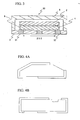
- a piezoelectric ceramic resonator 2 is constituted by forming a pair of vibrating electrodes 22, 23 on the front and back main faces of a polarized piezoelectric ceramic substrate 21, so that vibrations are trapped in the vicinity of the pair of vibrating electrodes 22, 23.
- a resonator 1 employing this piezoelectric ceramic resonator 2 comprises a substrate 3 and a cap 5.
- the substrate 3 has a strengthening function, and for example can be constituted from a ceramic such as steatite (MgO ⁇ SiO 2 ), alumina (Al 2 O 3 ) or the like. Such a substrate normally has a thickness of about 0.05 to 0.7 mm. Terminal electrodes 31, 32 are formed on the front and back faces of the substrate 3.
- the substrate 3 can also be constituted using a single-layer dielectric ceramic, a ceramic laminate or the like, so as to combine dielectric function with a strengthening function. Examples of a single-layer dielectric ceramic include compounds having barium titanate as a main component.
- Examples of a ceramic laminate include low-temperature sintered ceramics having internal electrodes, and can be obtained by, for example, simultaneously sintering Al 2 O 3 or CaZrO 3 to which a glass component has been added with a conductive paste of Cu, Ag or the like, at a temperature of 1,000°C or less.
- the piezoelectric ceramic resonator 2 is adhered and fixed onto the terminal electrodes 31, 32 by a conductive stator 4, such as a conductive resin or solder, which combines the functions of conduction and adherence.
- a conductive stator 4 such as a conductive resin or solder, which combines the functions of conduction and adherence.
- a constant vibration space can be secured according to the thickness of the conductive stator 4 in between the piezoelectric ceramic resonator 2 and substrate 3.
- the cap 5 is adhered onto the substrate 3 by an adhesive, for example, so as to cover the piezoelectric ceramic resonator 2.
- the cap 5 can be constituted from a ceramic such as steatite (MgO ⁇ SiO 2 ), alumina (Al 2 O 3 ) or the like as in the case of the substrate 3, it is also acceptable to constitute from an alloy or similar metal.
- the thickness of the cap 5 can be made about the same as that of the substrate 3.
- a resonator 1 such as that described above is disclosed in, for example, Japanese Patent Laid-OpenNo . 8-237066 (Patent Document 1).
- the piezoelectric ceramic resonator 2 is usually composed of a piezoelectric ceramic composition having a tetragonal or rhombohedral PZT (PbZr0 3 -PbTi0 3 solid solution)-based or PT (PbTi0 3 )-based perovskite structure at about room temperature, for example.
- the piezoelectric ceramic resonator 2 constituting the resonator 1 is required to possess a high mechanical strength in addition to the properties mentioned above. This is because product specifications require the piezoelectric ceramic resonator 2 to not have any abnormalities such as chips or cracks when the resonator 1 is allowed to free-fall onto concrete from a height of, for example, 1 meter (free-fall resistance). Therefore, since mechanical strength as required by a product specification is not itself a physical property, in the past the guidelines for how free-fall resistance could be improved were unclear. Moreover, while currently the height of fall (hereinbelow, the height of fall will be referred to "drop height”) when evaluating free-fall resistance is 1 meter, it is expected that in the future this drop height may be increased in response to demands for greater mechanical strength.
- the present invention was created based on such technical problems, wherein it is an obj ect thereof to provide a resonator having excellent free-fall resistance.
- the maximum elastic energy U per unit volume is obtained by the below formula (1) .
- the resonator according to the present invention is particularly effective when the substrate has a structure that comprises a terminal electrode wherein the piezoelectric ceramic resonator is supported at both ends on the substrate and in electrical continuity with the vibrating electrode via a conductive member.
- the present invention also encompasses a structure which supports a piezoelectric ceramic resonator on the substrate via some other member.
- the piezoelectric ceramic resonator preferably has a perovskite compound represented by Pb ⁇ [(Mn 1/3 Nb 2/3 ) x Ti y Zr z ]O 3 as a main component.
- a resonator can be provided which comprises a piezoelectric ceramic resonator having excellent free-fall resistance. Moreover, according to the present invention, if the maximum elastic energy U of the piezoelectric ceramic resonator is understood, a highly reliable resonator can be provided without conducting an actual drop test.
- FIG. 2 is a cross-sectional view for explaining the resonator 1 according to the present embodiment.
- the basic structure of the resonator 1 illustrated in FIG. 2 has been explained in the section entitled “Description of the Related Art", and thus repetitive explanation will be omitted here.
- U maximum elastic energy (kJ/m 3 )
- H drop height (m) (H > 1).
- Specimens comprising the following piezoelectric ceramics were subj ected to a three point bending test, whereby three point bending strength and three point bending elasticity modulus were measured. The maximum elastic energy U was obtained from these measurement results.
- the specimens were prepared in the following manner.
- the obtained compacted bodies were subjected to a treatment for removing the binder, and then were sintered in air at between 1,150 and 1, 250°C for 2 hours, whereby 7 types of sintered body were obtained. Both surfaces of each of the sintered bodies were flattened to a thickness of 0.5 mm using a lapping machine. The sintered bodies were then cut to 15.0 mm x 7.0 mm, after which temporary electrodes for polarization were formed on both ends thereof (in the 7.0 mm direction). The resulting objects underwent a polarizing treatment by applying a 3 kV/mm electric field for 20 minutes in a silicon oil bath having a temperature of 150°C.
- the polarization direction was made to be a direction parallel to the plate body, and the vibration mode was a thickness-shear mode.
- the temporary electrodes were subsequently removed.
- the size of the specimens after the temporary electrodes had been removed was 15 mm x 7 mm x 0.5 mm.
- Lapping was again carried out with the lapping machine to a thickness of 0.3 mm and 0.13 mm, and the specimens were cut out into length x width x thickness of 3.5 mm x 0.6 mm x 0.3 mm and length x width x thickness of 3.5 mm x 0.6 mm x 0.13 mm.
- the former specimens were for the piezoelectric ceramic resonator, and the latter specimens were for the three point bending tests.
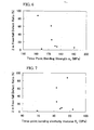
- the relationship between defect ratio and three point bending strength ⁇ b , the relationship between defect ratio and three point bending elasticity modulus E b , and the relationship between defect ratio and maximum elastic energy U are shown in FIGS. 6 to 8, respectively.
- the correlation between defect ratio and three point bending strength ⁇ b is generally strong, meaning that defect ratio can be lowered by increasing the three point bending strength ⁇ b .
- the defect ratio is low even though the three point bending strength ⁇ b is small.
- this is also the case for three point bending elasticity modulus E b .
- the three point bending strength ⁇ b and three point bending elasticity modulus E b there are no exceptions for maximum elastic energy U, wherein the correlation with defect ratio holds.
- the piezoelectric ceramic resonator 2 preparation procedures from the sintered body were as follows.
- Both sides of an above-described sintered body were flattened to a thickness of 0.5 mm using a lapping machine.
- the sintered body was then cut to 15.0 mm x 5.0 mm, and temporary electrodes for polarization were formed on both ends thereof (in the 5.0 mm direction).
- the resulting object underwent a polarizing treatment by applying a 3 kV/mm electric field for 20 minutes in a silicon oil bath having a temperature of 150°C.
- the polarization direction was made to be a direction parallel to the plate body, and the vibration mode was a thickness-shear mode.
- the temporary electrodes were subsequently removed.
- the size of the specimen after the temporary electrodes had been removed was 15 mm x 5.0 mm x 0.5 mm.
- Vibrating electrodes 22, 23 were formed using a vacuum evaporation apparatus.
- the vibrating electrodes 22, 23 were constituted from a 0.01 ⁇ m thick Cr under layer and 2 ⁇ m thick Ag.
- a 3.5 mm x 0.6 mm x 0.3 mm piezoelectric ceramic resonator 2 was prepared from the above specimen by cutting. Although this piezoelectric ceramic resonator 2 was adhered to the substrate 3 by a conductive stator 4, a vibrating space was secured by the rise in height due to the thickness of the conductive stator 4.
- This substrate 3 was constituted from steatite, and terminal electrodes 31, 32 were formed at the top and bottom surfaces thereof.
- the thickness of the substrate 3 was 0.45 mm thick.
- a cap 5 constituted from steatite was adhered to the substrate 3 so as to protect the piezoelectric ceramic resonator 2.
- the end potions were made to have a rough surface by barrel polishing, after which a thin-film electrode was deposited on a side face of the substrate 3 so as to connect the terminal electrodes 31, 32 formed on the top and bottom surfaces of the substrate 3.
- the dimensions of the final resonator 1 were 4.5 mm x 2.0 mm x 1.1 mm.
- the distance L between supports in the resonator 1 was set to be 4.06 ⁇ .
- t 3/2 x ⁇ wherein "t” denotes thickness.
- the distance L between supports is preferably 3 ⁇ or more, and more preferably 3.75 ⁇ or more . This is necessary so that the vibrations trapped in the vicinity of the vibrating electrodes 22, 23 are not suppressed.
- the upper limit for the distance L between supports is preferably set at 0.5 mm less than the outer form (L1 in FIG. 2) of the resonator 1, which is a necessary condition for securing the adhesion width of the airtight cap 5.
- this distance L between supports refers to the distance in a parallel direction to the polarization direction.
- the distance L between supports is still preferably 3 ⁇ or more, and more preferably 3.75 ⁇ or more.
- the distance L between supports refers to the distance in a longitudinal direction of the piezoelectric ceramic resonator 2.
- a resonator 1 having the configuration as illustrated in FIG. 2 was explained.
- application of the present invention is not limited to the resonator 1 illustrated in FIG. 2.
- a resonator 30 having the configuration illustrated in FIG. 3 can also be used.
- This resonator 30 is provided with a capacitative element 6 in between a substrate 3 and a piezoelectric ceramic resonator 2. It is noted that the elements in FIG. 3 which are the same as those in FIG. 2 have been given the same reference numerals as those in FIG. 2, and explanation thereof is omitted.
- the piezoelectric ceramic resonator 2 is not limited to the embodiment illustrated in FIG. 1. Various other embodiments for the piezoelectric ceramic resonator 2 can be used, such as an embodiment having a tapered shape as illustrated in FIG. 4A, or an embodiment into which grooves have been worked as illustrated in FIG. 4B, or the like.
- FIGS. 2 and 3 show the resonators 1, 30 having an embodiment wherein a piezoelectric ceramic resonator 2 is supported at both ends
- application of the present invention is not limited to such an embodiment wherein a piezoelectric ceramic resonator 2 is supported at both ends.
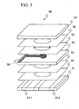
- the present invention can be applied to a resonator 50 having a configuration illustrated in FIG. 5.
- This resonator 50 has a structure wherein successively laminated are a substrate 51 provided with terminal electrodes 511 and 512, an adhesion resin layer 52, a hollow resin layer 53 , a piezoelectric ceramic resonator 54 provided with a vibrating electrode 541, a hollow resin layer 55, an adhesion resin layer 56, and a cover 57.
- the distance L between supports in the resonator 50 is indicated by the arrows.
- the hollow resin layers 53, 55 are provided to secure a vibration space so that the vibrations trapped in the vicinity of the vibrating electrode 541 are not suppressed. So that this space is maintained and to secure its air tightness, a cover 57 is adhered with an adhesion resin layer 56.
- a preferable piezoelectric ceramic composition and production method thereof will now be explained.
- the piezoelectric ceramic used in the present invention in which the main component is PZT having a perovskite type structure, preferably contains Mn or Nb as this main component. More preferable main components are represented by the following composition formula. It is noted that the term "chemical composition” as used here refers to the composition after sintering.
- the quantity ⁇ representing the Pb content is preferably limited to fall within the range of 0.97 ⁇ ⁇ ⁇ 1.01.
- ⁇ is less than 0.97, it is difficult to obtain a dense sintered body.
- ⁇ exceeds 1.01, no satisfactory heat resisting properties can be obtained.
- ⁇ is preferably limited to fall within the range of 0.97 ⁇ ⁇ ⁇ 1.01, more preferably 0.98 ⁇ ⁇ ⁇ 1.00, and furthermore preferably 0.99 ⁇ ⁇ ⁇ 1.00.
- the quantity x representing the Mn content and the Nb content is preferably limited to fall within the range of 0.04 ⁇ x ⁇ 0.16.
- x is less than 0.04, Q max becomes small.
- x exceeds 0.16, no satisfactory heat resisting properties can be obtained.
- x is preferably limited to fall within the range of 0.04 ⁇ x ⁇ 0.16, more preferably 0.06 ⁇ x ⁇ 0.14, and furthermore preferably 0.07 ⁇ x ⁇ 0.11.
- the quantity y representing the Ti content is limited to fall within the range of 0.48 ⁇ y ⁇ 0.58.
- y is less than 0.48, no satisfactory heat resisting properties can be obtained.
- y exceeds 0.58, no satisfactory temperature characteristics can be obtained.
- y is preferably limited to fall within the range of 0.48 ⁇ y ⁇ 0.58, more preferably 0.49 ⁇ y ⁇ 0.57, and furthermore preferably 0.50 ⁇ y ⁇ 0.55.
- the quantity z representing the Zr content is limited to fall within the range of 0.32 ⁇ z ⁇ 0.41. When z is less than 0.32 or exceeds 0.41, no satisfactory temperature characteristics can be obtained. Accordingly, z is preferably limited to fall within the range of 0.32 ⁇ z ⁇ 0.41, more preferably 0.33 ⁇ z ⁇ 0.40, and furthermore preferably 0.34 ⁇ z ⁇ 0.39. It is noted that the expression "temperature properties are good" refers to a small variation in piezoelectric ceramic properties as a consequence of temperature variation in an operating environment.
- one or more of Al 2 O 3 , SiO 2 , MnCO 3 and Cr 2 O 3 can be incorporated as additives into the main component.
- Al 2 O 3 and SiO 2 are effective in improving the mechanical strength of the piezoelectric ceramic.
- Al 2 O 3 it is preferable to add 0.15 wt% or more with respect to the main component, especially Pb ⁇ [(Mn 1/3 Nb 2/3 ) x Ti y Zr z ]O 3 , and adding 0.6 wt% or more is more preferable. If the added amount of Al 2 O 3 is too great, piezoelectric properties deteriorate, so that it is thus preferable to add 15.0 wt% or less with respect to the main component. More preferable is 5.0 wt% or less, and even more preferable is 1.5 wt% or less.
- the added amount of SiO 2 is preferably 0.005 to 0.15 wt% with respect to the main component, especially Pb ⁇ [(Mn 1/3 Nb 2/3 ) x TiyZr z ]O 3 .
- a more preferable added amount of SiO 2 is from 0.01 to 0.12 wt%, and an even more preferable added amount of SiO 2 is from 0.01 to 0.07 wt%.
- MnCO 3 is effective in improving sintering properties.
- a preferable MnCO 3 added amount is 0.65 wt% or less with respect to the main component, especially Pb ⁇ [(Mn 1/3 Nb 2/3 ) x Ti y Zr z ]O 3 , and a more preferable MnCO 3 added amount is 0.50 wt% or less.
- An even more preferable MnCO 3 added amount is from 0.01 to 0.40 wt%, and a much more preferable MnCO 3 added amount is from 0.05 to 0.3 wt%.
- Cr 2 O 3 is effective in attaining satisfactory heat resisting properties.
- a preferable Cr 2 O 3 added amount is 0.65 wt% or less with respect to the main component, especially Pb ⁇ [(Mn 1/3 Nb 2/3 ) x Ti y Zr z ]O 3 , and a more preferable Cr 2 O 3 added amount is 0.50 wt% or less.
- An even more preferable Cr 2 O 3 added amount is from 0.01 to 0.30 wt%, and a much more preferable Cr 2 O 3 added amount is from 0.01 to 0.10 wt%.
- the raw materials for the main components there may be used powders of oxides or powders of compounds to be converted to oxides when heated. More specifically, powders of PbO, TiO 2 , ZrO 2 , MnCO 3 , Nb 2 O 5 and the like can be used. The raw material powders were each weighed out so as to match the composition which is to be ultimately obtained. The foregoing is not limited to these raw material powders, and the powder of a complex oxide comprising two kinds or more of a metal may also be used as the raw material powders.
- the mean particle size of each of the raw material powders may be appropriately set somewhere within the range of 0.1 to 3.0 ⁇ m.
- the raw material powders are subjected to wet mixing and then calcinatedwhile beingmaintainedat a temperature ranging from 700 to 950°C for a predetermined period of time.
- This calcination may be conducted under the atmosphere of N 2 or air.
- the calcination time may be appropriately set within the range from 0.5 to 5 hours.
- the timing for adding the raw material powders of the additives is not limited to the above described timing.
- the powders of the main components may be weighed out, mixed, calcined and pulveri zed; and then, to the main component powder thus obtained after calcination and pulverization, the raw material powders of the additives may be added in respective predetermined amounts to make a mixture.
- the pulverized powder is granulated for the purpose of smoothly carrying out a subsequent compacting step.
- a small amount of an appropriate binder for example polyvinyl alcohol (PVA) is added to the pulverized powder, and they are fully mixed, and then a granulated powder is obtained by passing the mixed powder throughamesh, for example, for the purpose of sizing the powder particles.
- PVA polyvinyl alcohol
- the resulting granulated powder is compacted by pressing under a pressure of 200 to 300 MPa to obtain a compacted body having a desired shape.
- the compacted body After the binder, added at the time of compacting, has been removed from the compacted body, the compacted body is heated and maintained at a temperature within the range from 1100 to 1250°C for a predetermined period of time to obtain a sintered body.
- the atmosphere may be N 2 or air, and the compacted body may be heated and maintained appropriately within a range from 0.5 to 4 hours.
- the polarization is carried out.
- the polarization is conducted under the conditions such that the polarization temperature falls within the range from 50 to 300°C, and an electric field of 1.0 to 2.0 Ec (Ec being the coercive field) is applied to the sintered body for 0.5 to 30 minutes.
- the polarization temperature is set to fall within a range from 50 to 300°C.
- the polarization temperature is preferably 60 to 250°C, and more preferably 80 to 200°C.
- the electric filed to be applied in the polarization is set to be 1.0 to 2.0 Ec.
- the applied electric field is preferably 1.1 to 1.8 Ec, and more preferably 1.2 to 1.6 Ec.
- the polarization time is set to be 0.5 to 30 minutes.
- the polarization time is preferably 0.7 to 20 minutes, and more preferably 0.9 to 15 minutes.
- the polarization is conducted in a bath of an insulating oil such as a silicon oil heated to the above described temperature.
- the polarization direction is determined according to the desired vibration mode. Namely, in the case of thickness-shear mode, polarization can be carried out in a direction parallel to the main surface, while in thickness-extentional mode polarization can be carried out in a direction perpendicular to the main surface.
- the piezoelectric ceramic is lapped to a desired thickness, and thereafter vibrating electrodes are formed. Then, using a dicing saw or the like, the piezoelectric ceramic composition is cut into a desired shape so as to function as a piezoelectric ceramic resonator.
Abstract
Description
- The present invention relates to a resonator employing a piezoelectric ceramic resonator, and particularly relates to a resonator having excellent free-fall resistance.
- Piezoelectric resonating parts (resonators) which employ a piezoelectric ceramic resonator are known as resonators that attain an oscillating frequency. As illustrated in FIG. 1, a piezoelectric
ceramic resonator 2 is constituted by forming a pair of vibratingelectrodes ceramic substrate 21, so that vibrations are trapped in the vicinity of the pair of vibratingelectrodes ceramic resonator 2 comprises asubstrate 3 and acap 5. Thesubstrate 3 has a strengthening function, and for example can be constituted from a ceramic such as steatite (MgO·SiO2), alumina (Al2O3) or the like. Such a substrate normally has a thickness of about 0.05 to 0.7 mm.Terminal electrodes substrate 3. Thesubstrate 3 can also be constituted using a single-layer dielectric ceramic, a ceramic laminate or the like, so as to combine dielectric function with a strengthening function. Examples of a single-layer dielectric ceramic include compounds having barium titanate as a main component. Examples of a ceramic laminate include low-temperature sintered ceramics having internal electrodes, and can be obtained by, for example, simultaneously sintering Al2O3 or CaZrO3 to which a glass component has been added with a conductive paste of Cu, Ag or the like, at a temperature of 1,000°C or less. - The piezoelectric
ceramic resonator 2 is adhered and fixed onto theterminal electrodes conductive stator 4, such as a conductive resin or solder, which combines the functions of conduction and adherence. A constant vibration space can be secured according to the thickness of theconductive stator 4 in between the piezoelectricceramic resonator 2 andsubstrate 3. - The
cap 5 is adhered onto thesubstrate 3 by an adhesive, for example, so as to cover the piezoelectricceramic resonator 2. Although thecap 5 can be constituted from a ceramic such as steatite (MgO·SiO2), alumina (Al2O3) or the like as in the case of thesubstrate 3, it is also acceptable to constitute from an alloy or similar metal. The thickness of thecap 5 can be made about the same as that of thesubstrate 3. - A resonator 1 such as that described above is disclosed in, for example,
Japanese Patent Laid-OpenNo . 8-237066 - The piezoelectric
ceramic resonator 2 is usually composed of a piezoelectric ceramic composition having a tetragonal or rhombohedral PZT (PbZr03-PbTi03 solid solution)-based or PT (PbTi03)-based perovskite structure at about room temperature, for example. When a piezoelectricceramic resonator 2 is employed as a resonator 1, not only is a large band Qmax (Qmax = tanθ: wherein θ denotes phase angle) required for its electric properties, but along with the spreading use of surface mount devices in recent years, high heat resisting properties are also demanded because, when parts are mounted on print circuit boards, the boards are passed through a solder reflow furnace. Here, when heat resisting properties are referred to as "high" or "good" , this means that the variation in properties after being subj ected to thermal shock is small. - The piezoelectric
ceramic resonator 2 constituting the resonator 1 is required to possess a high mechanical strength in addition to the properties mentioned above. This is because product specifications require the piezoelectricceramic resonator 2 to not have any abnormalities such as chips or cracks when the resonator 1 is allowed to free-fall onto concrete from a height of, for example, 1 meter (free-fall resistance). Therefore, since mechanical strength as required by a product specification is not itself a physical property, in the past the guidelines for how free-fall resistance could be improved were unclear. Moreover, while currently the height of fall (hereinbelow, the height of fall will be referred to "drop height") when evaluating free-fall resistance is 1 meter, it is expected that in the future this drop height may be increased in response to demands for greater mechanical strength. - The present invention was created based on such technical problems, wherein it is an obj ect thereof to provide a resonator having excellent free-fall resistance.
- The present inventors have confirmed from free-fall drop tests on a resonator in which the drop height was varied that there is a strong correlation between defect ratio and the maximum elastic energy U and drop height of the piezoelectric ceramic resonator. That is, the present invention is a resonator comprising a piezoelectric ceramic resonator having a vibrating electrode, and a substrate which supports the piezoelectric ceramic resonator, wherein the piezoelectric ceramic resonator satisfies a condition that U ≥ 0.88 x H + 20.28, wherein U = maximum elastic energy (kJ/m3) per unit volume, and H = drop height (m) (H > 1) . The maximum elastic energy U per unit volume is obtained by the below formula (1) . In the below, with regards to U the words "per unit volume" will be omitted.

wherein σb is the three point bending strength and Eb is the three point bending modulus of elasticity. - The resonator according to the present invention is particularly effective when the substrate has a structure that comprises a terminal electrode wherein the piezoelectric ceramic resonator is supported at both ends on the substrate and in electrical continuity with the vibrating electrode via a conductive member. Thus, the present invention also encompasses a structure which supports a piezoelectric ceramic resonator on the substrate via some other member.
- Further, in the resonator according to the present invention, the piezoelectric ceramic resonator preferably has a perovskite compound represented by Pbα[(Mn1/3Nb2/3)xTiyZrz]O3 as a main component.
- However, in the above composition formula, 0.97 ≤ α ≤ 1.01, 0.04 ≤ x ≤ 0.16, 0.48 ≤ y ≤ 0.58, 0.32 ≤ z ≤ 0.41.
- According to the present invention, a resonator can be provided which comprises a piezoelectric ceramic resonator having excellent free-fall resistance. Moreover, according to the present invention, if the maximum elastic energy U of the piezoelectric ceramic resonator is understood, a highly reliable resonator can be provided without conducting an actual drop test.
-
- FIG. 1 is a perspective view illustrating the configuration of a piezoelectric ceramic resonator;
- FIG. 2 is a cross-sectional view illustrating the configuration of a resonator;
- FIG. 3 is a cross-sectional view illustrating another configuration of a resonator;
- FIGS. 4A and 4B are side views illustrating another configuration of a piezoelectric ceramic resonator;
- FIG. 5 is a cross-sectional view illustrating another configuration of a resonator;
- FIG. 6 is a graph illustrating the relationship between three point bending strength σb and defect ratio in a drop test;
- FIG. 7 is a graph illustrating the relationship between three point bending elasticity modulus Eb and defect ratio in a drop test;
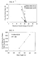
- FIG. 8 is a graph illustrating the relationship between maximum elastic energy U and defect ratio in a drop test; and
- FIG. 9 is a graph illustrating the relationship between drop height H and maximum elastic energy U where the defect ratio reaches 0%.
- The present invention will now be described in more detail based on the embodiments.
- FIG. 2 is a cross-sectional view for explaining the resonator 1 according to the present embodiment. The basic structure of the resonator 1 illustrated in FIG. 2 has been explained in the section entitled "Description of the Related Art", and thus repetitive explanation will be omitted here.
- The present invention is characterized in that the piezoelectric
ceramic resonator 2, which is a constituent feature of the resonator 1, satisfies the condition U ≥ 0.88 x H + 20.28 wherein U = maximum elastic energy (kJ/m3), and H = drop height (m) (H > 1). By satisfying this condition, the occurrence of defects such as chips or cracks in the piezoelectricceramic resonator 2 can be prevented when the resonator 1 is dropped from a certain height. The drop tests from which this condition was derived will now be explained. - Specimens comprising the following piezoelectric ceramics were subj ected to a three point bending test, whereby three point bending strength and three point bending elasticity modulus were measured. The maximum elastic energy U was obtained from these measurement results. The specimens were prepared in the following manner.
- As starting raw materials, there were prepared powders of lead oxide (PbO), titanium oxide (TiO2), zirconium oxide (ZrO2), manganese carbonate (MnCO3), niobium oxide (Nb2O5), aluminumoxide (Al2O3), siliconoxide (SiO2), andchromiumoxide (Cr2O3). These raw material powders were weighed out to have the molar ratio Pb0.99 [(Mn1/3Nb2/3)0.10Ti0.53Zr0.37]O3. The below additives were then added with respect to the total weight of the respective raw material powders. Each mixture underwent wet mixing for 10 hours using a ball mill, whereby 7 types of slurry were prepared.
(1) MnCO3 powder: 0.2 wt% (2) MnCO3 powder: 0.2 wt%, SiO2 powder: 0.02 wt% (3) MnCO3 powder: 0.3 wt%, SiO2 powder: 0.1 wt% (4) A12O3 powder: 0.5 wt%, SiO2 powder: 0.02 wt% (5) Al2O3 powder: 0.7 wt%, SiO2 powder: 0.02 wt% (6) Al2O3 powder: 1.0 wt%, SiO2 powder: 0.02 wt% (7) Cr2O3 powder: 0.1 wt%, SiO2 powder: 0.02 wt% - These obtained slurries were well dried and each subj ected to a press compacting and thereafter to a calcination in air by being held at 800°C for 2 hours. The calcined bodies were finely pulverized with a ball mill to a mean particle size of 0.7µm, after which the finely pulverized powders were dried. The dried, finely pulverized powders were charged with a suitable amount of PVA (polyvinyl alcohol) as a binder to thereby produce granules. About 3 g of these granules were charged into a die having 20 mm long x 20 mm wide cavities. A uniaxial press machine was used to perform compacting at a pressure of 245 MPa. The obtained compacted bodies were subjected to a treatment for removing the binder, and then were sintered in air at between 1,150 and 1, 250°C for 2 hours, whereby 7 types of sintered body were obtained. Both surfaces of each of the sintered bodies were flattened to a thickness of 0.5 mm using a lapping machine. The sintered bodies were then cut to 15.0 mm x 7.0 mm, after which temporary electrodes for polarization were formed on both ends thereof (in the 7.0 mm direction). The resulting objects underwent a polarizing treatment by applying a 3 kV/mm electric field for 20 minutes in a silicon oil bath having a temperature of 150°C. The polarization direction was made to be a direction parallel to the plate body, and the vibration mode was a thickness-shear mode. The temporary electrodes were subsequently removed. The size of the specimens after the temporary electrodes had been removed was 15 mm x 7 mm x 0.5 mm. Lapping was again carried out with the lapping machine to a thickness of 0.3 mm and 0.13 mm, and the specimens were cut out into length x width x thickness of 3.5 mm x 0.6 mm x 0.3 mm and length x width x thickness of 3.5 mm x 0.6 mm x 0.13 mm. The former specimens were for the piezoelectric ceramic resonator, and the latter specimens were for the three point bending tests.
- The three point bending tests were carried out in accordance with JIS R1601 using the above-described specimens under the below conditions.
Crosshead speed: 0.10 mm/min - Crosshead radius of curvature/distance between support points = 0.077 (crosshead radius of curvature = 0.2 mm; distance between support points = 2.6 mm)
- Next, once a piezoelectric
ceramic resonator 2 had been prepared from the above-described specimens and integrated into the resonator 1 illustrated in FIG. 2, a free-fall drop test was conducted onto concrete. Three drop heights H of 1.0 m, 1.5 m and 2.0 m were used, wherein dropping was carried out three times for each height. - For the drop tests wherein the drop height H was 2.0 m, the relationship between defect ratio and three point bending strength σb, the relationship between defect ratio and three point bending elasticity modulus Eb, and the relationship between defect ratio and maximum elastic energy U are shown in FIGS. 6 to 8, respectively. As illustrated in FIG. 6, the correlation between defect ratio and three point bending strength σb is generally strong, meaning that defect ratio can be lowered by increasing the three point bending strength σb. However, in some cases the defect ratio is low even though the three point bending strength σb is small. As illustrated in FIG. 7, this is also the case for three point bending elasticity modulus Eb. On the other hand, unlike the three point bending strength σb and three point bending elasticity modulus Eb, there are no exceptions for maximum elastic energy U, wherein the correlation with defect ratio holds.
- Based on the above-described relationship between defect ratio (%) and maximum elastic energy U, obtaining the maximum elastic energy Uo, wherein the defect ratio reaches 0% for the respective drop height H, gave the following.
Drop height 1.0 m: Uo = 21.2 kJ/m3 Drop height 1.5 m: Uo = 21.6 kJ/m3 Drop height 2.0 m: Uo = 22.1 kJ/m3 - From the above results it is possible to obtain the relationship between the drop height H and the maximum elastic energy U wherein the defect ratio can reach 0%. As illustrated in FIG. 9, this relationship is U ≥ 0.88 x H + 20.28 wherein H = drop height (m), H > 1) . Thus, the present invention uses a piezoelectric
ceramic resonator 2 which satisfies this condition. "R" in FIG. 9 denotes a correlation coefficient, and R2 denotes the square value thereof. - The piezoelectric
ceramic resonator 2 preparation procedures from the sintered body were as follows. - Both sides of an above-described sintered body were flattened to a thickness of 0.5 mm using a lapping machine. The sintered body was then cut to 15.0 mm x 5.0 mm, and temporary electrodes for polarization were formed on both ends thereof (in the 5.0 mm direction). The resulting object underwent a polarizing treatment by applying a 3 kV/mm electric field for 20 minutes in a silicon oil bath having a temperature of 150°C. The polarization direction was made to be a direction parallel to the plate body, and the vibration mode was a thickness-shear mode. The temporary electrodes were subsequently removed. The size of the specimen after the temporary electrodes had been removed was 15 mm x 5.0 mm x 0.5 mm. Lapping was again carried out with the lapping machine to a thickness of 0.3 mm. Vibrating
electrodes electrodes electrodes ceramic resonator 2 was prepared from the above specimen by cutting. Although this piezoelectricceramic resonator 2 was adhered to thesubstrate 3 by aconductive stator 4, a vibrating space was secured by the rise in height due to the thickness of theconductive stator 4. Thissubstrate 3 was constituted from steatite, andterminal electrodes substrate 3 was 0.45 mm thick. Next, acap 5 constituted from steatite was adhered to thesubstrate 3 so as to protect the piezoelectricceramic resonator 2. Finally, the end potions were made to have a rough surface by barrel polishing, after which a thin-film electrode was deposited on a side face of thesubstrate 3 so as to connect theterminal electrodes substrate 3. The dimensions of the final resonator 1 were 4.5 mm x 2.0 mm x 1.1 mm. - The distance L between supports in the resonator 1 was set to be 4.06 λ. λ is the wavelength of the piezoelectric
ceramic resonator 2, wherein for the fundamental wave the relation t = 1/2 x λ wherein "t" denotes thickness holds true. When using a third harmonic, t = 3/2 x λ wherein "t" denotes thickness. - Here, in the case of thickness-shear mode, the distance L between supports is preferably 3 λ or more, and more preferably 3.75 λ or more . This is necessary so that the vibrations trapped in the vicinity of the vibrating
electrodes airtight cap 5. Here this distance L between supports refers to the distance in a parallel direction to the polarization direction. - Further, when the polarization direction is a thickness-extentional mode with respect to the main surface, the distance L between supports is still preferably 3 λ or more, and more preferably 3.75 λ or more. In this case the distance L between supports refers to the distance in a longitudinal direction of the piezoelectric
ceramic resonator 2. - In the above embodiment a resonator 1 having the configuration as illustrated in FIG. 2 was explained. However, it goes without saying that application of the present invention is not limited to the resonator 1 illustrated in FIG. 2. For example, a
resonator 30 having the configuration illustrated in FIG. 3 can also be used. Thisresonator 30 is provided with acapacitative element 6 in between asubstrate 3 and a piezoelectricceramic resonator 2. It is noted that the elements in FIG. 3 which are the same as those in FIG. 2 have been given the same reference numerals as those in FIG. 2, and explanation thereof is omitted. - Moreover, the piezoelectric
ceramic resonator 2 is not limited to the embodiment illustrated in FIG. 1. Various other embodiments for the piezoelectricceramic resonator 2 can be used, such as an embodiment having a tapered shape as illustrated in FIG. 4A, or an embodiment into which grooves have been worked as illustrated in FIG. 4B, or the like. - While FIGS. 2 and 3 show the
resonators 1, 30 having an embodiment wherein a piezoelectricceramic resonator 2 is supported at both ends, application of the present invention is not limited to such an embodiment wherein a piezoelectricceramic resonator 2 is supported at both ends. For example, the present invention can be applied to aresonator 50 having a configuration illustrated in FIG. 5. Thisresonator 50 has a structure wherein successively laminated are asubstrate 51 provided withterminal electrodes adhesion resin layer 52, ahollow resin layer 53 , a piezoelectricceramic resonator 54 provided with a vibratingelectrode 541, ahollow resin layer 55, anadhesion resin layer 56, and acover 57. The distance L between supports in theresonator 50 is indicated by the arrows. The hollow resin layers 53, 55 are provided to secure a vibration space so that the vibrations trapped in the vicinity of the vibratingelectrode 541 are not suppressed. So that this space is maintained and to secure its air tightness, acover 57 is adhered with anadhesion resin layer 56. - As explained above, the present invention is characterized by using a piezoelectric ceramic composition which satisfies the condition U ≥ 0.88 x H + 20.28, wherein H = drop height (m), H > 1. A preferable piezoelectric ceramic composition and production method thereof will now be explained.
- The piezoelectric ceramic used in the present invention, in which the main component is PZT having a perovskite type structure, preferably contains Mn or Nb as this main component. More preferable main components are represented by the following composition formula. It is noted that the term "chemical composition" as used here refers to the composition after sintering.

wherein in the composition formula α, x, y and z fall within the ranges of 0.97 ≤ α ≤ 1.01, 0.04 ≤ x ≤ 0.16, 0.48 ≤ y ≤ 0.58 and 0.32 ≤ z ≤ 0.41, respectively, and α, x, y and z each represent a molar ratio. - The reasons for imposing limitations on α, x, y and z in the composition formula are as follows.
- The quantity α representing the Pb content is preferably limited to fall within the range of 0.97 ≤ α ≤ 1.01. When α is less than 0.97, it is difficult to obtain a dense sintered body. On the other hand, when α exceeds 1.01, no satisfactory heat resisting properties can be obtained. Accordingly, α is preferably limited to fall within the range of 0.97 ≤ α ≤ 1.01, more preferably 0.98 ≤ α < 1.00, and furthermore preferably 0.99 ≤ α < 1.00.
- The quantity x representing the Mn content and the Nb content is preferably limited to fall within the range of 0.04 ≤ x ≤ 0.16. When x is less than 0.04, Qmax becomes small. On the other hand, when x exceeds 0.16, no satisfactory heat resisting properties can be obtained. Accordingly, x is preferably limited to fall within the range of 0.04 ≤ x ≤ 0.16, more preferably 0.06 ≤ x ≤ 0.14, and furthermore preferably 0.07 ≤ x ≤ 0.11.
- The quantity y representing the Ti content is limited to fall within the range of 0.48 ≤ y ≤ 0.58. When y is less than 0.48, no satisfactory heat resisting properties can be obtained. On the other hand, when y exceeds 0.58, no satisfactory temperature characteristics can be obtained. Accordingly, y is preferably limited to fall within the range of 0.48 ≤ y ≤ 0.58, more preferably 0.49 ≤ y ≤ 0.57, and furthermore preferably 0.50 ≤ y ≤ 0.55.
- The quantity z representing the Zr content is limited to fall within the range of 0.32 ≤ z ≤ 0.41. When z is less than 0.32 or exceeds 0.41, no satisfactory temperature characteristics can be obtained. Accordingly, z is preferably limited to fall within the range of 0.32 ≤ z ≤ 0.41, more preferably 0.33 ≤ z ≤ 0.40, and furthermore preferably 0.34 ≤ z ≤ 0.39. It is noted that the expression "temperature properties are good" refers to a small variation in piezoelectric ceramic properties as a consequence of temperature variation in an operating environment.
- For the piezoelectric ceramic used in the present invention, one or more of Al2O3, SiO2, MnCO3 and Cr2O3 can be incorporated as additives into the main component.
- Al2O3 and SiO2 are effective in improving the mechanical strength of the piezoelectric ceramic. For Al2O3, it is preferable to add 0.15 wt% or more with respect to the main component, especially Pbα[(Mn1/3Nb2/3)xTiyZrz]O3, and adding 0.6 wt% or more is more preferable. If the added amount of Al2O3 is too great, piezoelectric properties deteriorate, so that it is thus preferable to add 15.0 wt% or less with respect to the main component. More preferable is 5.0 wt% or less, and even more preferable is 1.5 wt% or less. Further, the added amount of SiO2 is preferably 0.005 to 0.15 wt% with respect to the main component, especially Pbα[(Mn1/3Nb2/3)xTiyZrz]O3. A more preferable added amount of SiO2 is from 0.01 to 0.12 wt%, and an even more preferable added amount of SiO2 is from 0.01 to 0.07 wt%.
- MnCO3 is effective in improving sintering properties. When incorporating MnCO3 as an additive, a preferable MnCO3 added amount is 0.65 wt% or less with respect to the main component, especially Pbα[(Mn1/3Nb2/3)xTiyZrz]O3, and a more preferable MnCO3 added amount is 0.50 wt% or less. An even more preferable MnCO3 added amount is from 0.01 to 0.40 wt%, and a much more preferable MnCO3 added amount is from 0.05 to 0.3 wt%.
- Cr2O3 is effective in attaining satisfactory heat resisting properties. A preferable Cr2O3 added amount is 0.65 wt% or less with respect to the main component, especially Pbα[(Mn1/3Nb2/3)xTiyZrz]O3, and a more preferable Cr2O3 added amount is 0.50 wt% or less. An even more preferable Cr2O3 added amount is from 0.01 to 0.30 wt%, and a much more preferable Cr2O3 added amount is from 0.01 to 0.10 wt%.
- It is noted that the above additives were merely cited as one preferable example, and the use of other additives is not excluded.
- Next, a preferable production method of the piezoelectric ceramic used in the present invention will be described below by following the relevant steps in order.
- As the raw materials for the main components, there may be used powders of oxides or powders of compounds to be converted to oxides when heated. More specifically, powders of PbO, TiO2, ZrO2, MnCO3, Nb2O5 and the like can be used. The raw material powders were each weighed out so as to match the composition which is to be ultimately obtained. The foregoing is not limited to these raw material powders, and the powder of a complex oxide comprising two kinds or more of a metal may also be used as the raw material powders.
- Then, in relation to the total weight of these weighed powders, predetermined amounts of additives are added. The mean particle size of each of the raw material powders may be appropriately set somewhere within the range of 0.1 to 3.0 µm.
- The raw material powders are subjected to wet mixing and then calcinatedwhile beingmaintainedat a temperature ranging from 700 to 950°C for a predetermined period of time. This calcination may be conducted under the atmosphere of N2 or air. The calcination time may be appropriately set within the range from 0.5 to 5 hours.
- It has been described above that the raw material powders of the main components and the raw material powders of the additives are mixed together, and then both of them are subjected to calcination. However, the timing for adding the raw material powders of the additives is not limited to the above described timing. As an alternative example, firstly the powders of the main components may be weighed out, mixed, calcined and pulveri zed; and then, to the main component powder thus obtained after calcination and pulverization, the raw material powders of the additives may be added in respective predetermined amounts to make a mixture.
- The pulverized powder is granulated for the purpose of smoothly carrying out a subsequent compacting step. At this time, a small amount of an appropriate binder, for example polyvinyl alcohol (PVA) is added to the pulverized powder, and they are fully mixed, and then a granulated powder is obtained by passing the mixed powder throughamesh, for example, for the purpose of sizing the powder particles. Then, the resulting granulated powder is compacted by pressing under a pressure of 200 to 300 MPa to obtain a compacted body having a desired shape.
- After the binder, added at the time of compacting, has been removed from the compacted body, the compacted body is heated and maintained at a temperature within the range from 1100 to 1250°C for a predetermined period of time to obtain a sintered body. In this sintering, the atmosphere may be N2 or air, and the compacted body may be heated and maintained appropriately within a range from 0.5 to 4 hours.
- After electrodes for the polarization have been formed on the sintered body, the polarization is carried out. The polarization is conducted under the conditions such that the polarization temperature falls within the range from 50 to 300°C, and an electric field of 1.0 to 2.0 Ec (Ec being the coercive field) is applied to the sintered body for 0.5 to 30 minutes.
- When the polarization temperature is lower than 50°C, the Ec is elevated and accordingly the voltage for polarization becomes so high that the polarization is difficult to occur. On the other hand, when the polarization temperature exceeds 300°C, the insulation property of the insulating oil is lowered so markedly that the polarization is difficult to occur. Consequently, the polarization temperature is set to fall within a range from 50 to 300°C. The polarization temperature is preferably 60 to 250°C, and more preferably 80 to 200°C.
- When the applied electric field is lower than 1.0 Ec, the polarization does not proceed. On the other hand, when the applied electric field is higher than 2.0 Ec, the actual voltage becomes high, so that the breakdown of sintered body tends to occur and accordingly it becomes difficult to prepare a piezoelectric ceramic. Accordingly, the electric filed to be applied in the polarization is set to be 1.0 to 2.0 Ec. The applied electric field is preferably 1.1 to 1.8 Ec, and more preferably 1.2 to 1.6 Ec.
- When the polarization time is less than 0.5 minute, the polarization is not progressed to a sufficient extent, so that the properties cannot be attained to a sufficient extent. On the other hand, when the polarization time exceeds 30 minutes, the time required for the polarization becomes long, so that the production efficiency is degraded. Accordingly, the polarization time is set to be 0.5 to 30 minutes. The polarization time is preferably 0.7 to 20 minutes, and more preferably 0.9 to 15 minutes.
- The polarization is conducted in a bath of an insulating oil such as a silicon oil heated to the above described temperature. Incidentally, the polarization direction is determined according to the desired vibration mode. Namely, in the case of thickness-shear mode, polarization can be carried out in a direction parallel to the main surface, while in thickness-extentional mode polarization can be carried out in a direction perpendicular to the main surface.
- The piezoelectric ceramic is lapped to a desired thickness, and thereafter vibrating electrodes are formed. Then, using a dicing saw or the like, the piezoelectric ceramic composition is cut into a desired shape so as to function as a piezoelectric ceramic resonator.
Claims (11)
- A resonator comprising:a piezoelectric ceramic resonator with a vibrating electrode formed; anda substrate which supports the piezoelectric ceramic resonator, wherein the piezoelectric ceramic resonator satisfies a condition of U ≥ 0.88 x H + 20.28, wherein U = maximum elastic energy (kJ/m3) per unit volume, and H = drop height (m) (H > 1).
- The resonator according to claim 1, wherein the substrate comprises a terminal electrode, and the piezoelectric ceramic resonator is supported on the substrate at both ends and is in electrical continuity with the vibrating electrode via a conductive member.
- The resonator according to claim 1 or 2, wherein the piezoelectric ceramic resonator comprises a perovskite compound represented by Pbα [(Mn1/3Nb2/3)xTiyZrz] O3 as a main component, wherein in the composition formula, 0.97 ≤ α ≤ 1.01, 0.04 ≤ x ≤ 0.16, 0.48 ≤ y ≤ 0.58, and 0.32 ≤ z ≤ 0.41.
- The resonator according to claim 3, wherein α falls within the range: 0.98 ≤ α < 1.00.
- The resonator according to claim 3 wherein x falls within the range: 0.06 ≤ x ≤ 0.14.
- The resonator according to claim 3, wherein y falls within the range: 0.49 ≤ y ≤ 0.57.
- The resonator according to claim 3, wherein z falls within the range: 0.33 ≤ z ≤ 0.40.
- The resonator according to claim 3, wherein the piezoelectric ceramic resonator comprises, as an additive, Al in a content of 5.0 wt% or less in terms of Al2O3.
- The resonator according to claim 3, wherein the piezoelectric ceramic resonator comprises, as an additive, Si in a content of 0.005 to 0.15 wt% in terms of SiO2.
- The resonator according to claim 3, wherein the piezoelectric ceramic resonator comprises, as an additive, Mn in a content of 0.65 wt% or less in terms of MnCO3.
- The resonator according to claim 3, wherein the piezoelectric ceramic resonator comprises, as an additive, Cr in a content of 0.65 wt% or less in terms of Cr2O3.
Applications Claiming Priority (1)
| Application Number | Priority Date | Filing Date | Title |
|---|---|---|---|
| JP2005111507A JP4338091B2 (en) | 2005-04-08 | 2005-04-08 | Resonator |
Publications (2)
| Publication Number | Publication Date |
|---|---|
| EP1710911A2 true EP1710911A2 (en) | 2006-10-11 |
| EP1710911A3 EP1710911A3 (en) | 2007-09-05 |
Family
ID=36648577
Family Applications (1)
| Application Number | Title | Priority Date | Filing Date |
|---|---|---|---|
| EP20060007382 Withdrawn EP1710911A3 (en) | 2005-04-08 | 2006-04-07 | Resonator |
Country Status (4)
| Country | Link |
|---|---|
| US (1) | US7541716B2 (en) |
| EP (1) | EP1710911A3 (en) |
| JP (1) | JP4338091B2 (en) |
| CN (1) | CN1845454A (en) |
Cited By (1)
| Publication number | Priority date | Publication date | Assignee | Title |
|---|---|---|---|---|
| WO2018059949A1 (en) * | 2016-09-30 | 2018-04-05 | Robert Bosch Gmbh | Single piezoelectric transmitter and receiver to detect blood velocities |
Families Citing this family (7)
| Publication number | Priority date | Publication date | Assignee | Title |
|---|---|---|---|---|
| US8101061B2 (en) * | 2004-03-05 | 2012-01-24 | Board Of Regents, The University Of Texas System | Material and device properties modification by electrochemical charge injection in the absence of contacting electrolyte for either local spatial or final states |
| JP2008094706A (en) * | 2006-09-12 | 2008-04-24 | Tdk Corp | Piezoelectric ceramic composition and rezonator |
| JP5018648B2 (en) * | 2008-05-29 | 2012-09-05 | Tdk株式会社 | Piezoelectric ceramic and resonator using the same |
| CN103367859B (en) * | 2012-03-31 | 2017-08-11 | 深圳光启创新技术有限公司 | A kind of harmonic oscillator |
| CN103360082B (en) * | 2012-03-31 | 2016-09-14 | 深圳光启创新技术有限公司 | A kind of harmonic oscillator and preparation method, dielectric filter |
| CN103360100B (en) * | 2012-03-31 | 2016-05-04 | 深圳光启创新技术有限公司 | A kind of method of preparing harmonic oscillator |
| WO2015060120A1 (en) * | 2013-10-23 | 2015-04-30 | 株式会社村田製作所 | Crystal oscillation device |
Citations (3)
| Publication number | Priority date | Publication date | Assignee | Title |
|---|---|---|---|---|
| JPS58190115A (en) * | 1982-04-28 | 1983-11-07 | Fujitsu Ltd | Piezoelectric oscillator |
| US4583019A (en) * | 1983-05-30 | 1986-04-15 | Fujitsu Limited | Piezoelectric resonator using 165° Y-cut LiNbO3 |
| EP1309084A1 (en) * | 2001-06-11 | 2003-05-07 | Matsushita Electric Industrial Co., Ltd. | Piezoelectric vibrator and filter using the same |
Family Cites Families (11)
| Publication number | Priority date | Publication date | Assignee | Title |
|---|---|---|---|---|
| US3699045A (en) * | 1967-12-22 | 1972-10-17 | Nippon Electric Co | Piezoelectric ceramic-material |
| JPH0559951U (en) * | 1992-01-09 | 1993-08-06 | 株式会社村田製作所 | Piezoelectric parts |
| JPH08237066A (en) | 1995-02-24 | 1996-09-13 | Murata Mfg Co Ltd | Piezoelectric resonator and its manufacture |
| CN1111950C (en) * | 1997-01-13 | 2003-06-18 | 精工爱普生株式会社 | The manufacture method of piezoelectric vibrator, piezoelectric vibrator and piezoelectric vibrator unit |
| JP3562402B2 (en) | 1999-09-29 | 2004-09-08 | 株式会社村田製作所 | Piezoelectric ceramic material and surface wave device using the same |
| JP4547788B2 (en) * | 2000-03-15 | 2010-09-22 | セイコーエプソン株式会社 | Package structure of piezoelectric vibrator |
| JP2002057544A (en) * | 2000-08-09 | 2002-02-22 | Murata Mfg Co Ltd | Piezoelectric oscillator |
| WO2002073710A1 (en) * | 2001-03-12 | 2002-09-19 | Ngk Insulators,Ltd. | Piezoelectric/electrostrictive film type actuator and method of manufacturing the actuator |
| KR100420929B1 (en) * | 2001-05-26 | 2004-03-02 | 한국과학기술연구원 | High density piezoelectric thick film and manufacturing method thereof |
| DE60239464D1 (en) * | 2001-06-15 | 2011-04-28 | Tdk Corp | PIEZOELECTRIC PORCELAIN AND METHOD FOR THE PRODUCTION THEREOF |
| DE602004024626D1 (en) * | 2003-09-24 | 2010-01-28 | Tdk Corp | Piezoelectric ceramic composition and manufacture thereof, and piezoelectric element |
-
2005
- 2005-04-08 JP JP2005111507A patent/JP4338091B2/en not_active Expired - Fee Related
-
2006
- 2006-04-04 US US11/397,952 patent/US7541716B2/en not_active Expired - Fee Related
- 2006-04-07 EP EP20060007382 patent/EP1710911A3/en not_active Withdrawn
- 2006-04-07 CN CNA2006100741771A patent/CN1845454A/en active Pending
Patent Citations (3)
| Publication number | Priority date | Publication date | Assignee | Title |
|---|---|---|---|---|
| JPS58190115A (en) * | 1982-04-28 | 1983-11-07 | Fujitsu Ltd | Piezoelectric oscillator |
| US4583019A (en) * | 1983-05-30 | 1986-04-15 | Fujitsu Limited | Piezoelectric resonator using 165° Y-cut LiNbO3 |
| EP1309084A1 (en) * | 2001-06-11 | 2003-05-07 | Matsushita Electric Industrial Co., Ltd. | Piezoelectric vibrator and filter using the same |
Cited By (2)
| Publication number | Priority date | Publication date | Assignee | Title |
|---|---|---|---|---|
| WO2018059949A1 (en) * | 2016-09-30 | 2018-04-05 | Robert Bosch Gmbh | Single piezoelectric transmitter and receiver to detect blood velocities |
| US11717254B2 (en) | 2016-09-30 | 2023-08-08 | Robert Bosch Gmbh | Single piezoelectric transmitter and receiver to detect blood velocities |
Also Published As
| Publication number | Publication date |
|---|---|
| CN1845454A (en) | 2006-10-11 |
| EP1710911A3 (en) | 2007-09-05 |
| US20060250050A1 (en) | 2006-11-09 |
| JP2006295418A (en) | 2006-10-26 |
| JP4338091B2 (en) | 2009-09-30 |
| US7541716B2 (en) | 2009-06-02 |
Similar Documents
| Publication | Publication Date | Title |
|---|---|---|
| EP1710911A2 (en) | Resonator | |
| KR101541022B1 (en) | Piezoelectric material, piezoelectric element, liquid discharge head, ultrasonic motor, and dust removing device | |
| EP1728773A1 (en) | Piezoelectric ceramic composition | |
| KR101235434B1 (en) | Piezoelectric ceramic composition and piezoelectric element made by using the same | |
| JP2006108639A (en) | Piezoelectric actuator | |
| JP2006105964A (en) | Piezoelectric sensor | |
| US20110074516A1 (en) | Piezoelectric ceramic composition, piezoelectric ceramic, piezoelectric element, and oscillator | |
| EP2677558A1 (en) | Piezoelectric element | |
| EP2452929B1 (en) | Piezoelectric body/electrostrictive body, piezoelectric/electrostrictive ceramic composition, piezoelectric element/electrostrictive element, and piezoelectric motor | |
| JP5129067B2 (en) | Piezoelectric / electrostrictive porcelain composition and piezoelectric / electrostrictive element | |
| US20090065731A1 (en) | Method for producing piezoelectric ceramic | |
| US8212457B2 (en) | Piezoelectric ceramic composition, piezoelectric element, and resonator | |
| US11005028B2 (en) | Piezoelectric composition and piezoelectric element | |
| JP4169203B2 (en) | Piezoelectric ceramic composition | |
| JP4404217B2 (en) | Piezoelectric element | |
| CN100391895C (en) | Piezoelectric ceramic composition | |
| US20080258100A1 (en) | Piezoelectric ceramic composition and resonator | |
| EP2287128B1 (en) | Piezoelectric/electrostrictive ceramic composition | |
| EP2119686B1 (en) | Piezoelectric ceramic material and piezoelectric element | |
| US7608215B2 (en) | Method of manufacturing a piezoelectric ceramic composition | |
| JPH11322422A (en) | Piezoelectric ceramic material | |
| US20060043329A1 (en) | Piezoelectric ceramic composition | |
| JP3981221B2 (en) | Piezoelectric ceramic | |
| WO2024070626A1 (en) | Lead-free piezoelectric composition, and piezoelectric element | |
| JP2007258597A (en) | Method for polarizing piezoelectric element |
Legal Events
| Date | Code | Title | Description |
|---|---|---|---|
| PUAI | Public reference made under article 153(3) epc to a published international application that has entered the european phase |
Free format text: ORIGINAL CODE: 0009012 |
|
| AK | Designated contracting states |
Kind code of ref document: A2 Designated state(s): AT BE BG CH CY CZ DE DK EE ES FI FR GB GR HU IE IS IT LI LT LU LV MC NL PL PT RO SE SI SK TR |
|
| AX | Request for extension of the european patent |
Extension state: AL BA HR MK YU |
|
| PUAL | Search report despatched |
Free format text: ORIGINAL CODE: 0009013 |
|
| AK | Designated contracting states |
Kind code of ref document: A3 Designated state(s): AT BE BG CH CY CZ DE DK EE ES FI FR GB GR HU IE IS IT LI LT LU LV MC NL PL PT RO SE SI SK TR |
|
| AX | Request for extension of the european patent |
Extension state: AL BA HR MK YU |
|
| 17P | Request for examination filed |
Effective date: 20071121 |
|
| 17Q | First examination report despatched |
Effective date: 20071221 |
|
| AKX | Designation fees paid |
Designated state(s): DE NL |
|
| STAA | Information on the status of an ep patent application or granted ep patent |
Free format text: STATUS: THE APPLICATION HAS BEEN WITHDRAWN |
|
| 18W | Application withdrawn |
Effective date: 20111028 |