EP1710638A1 - Controller - Google Patents
Controller Download PDFInfo
- Publication number
- EP1710638A1 EP1710638A1 EP06006564A EP06006564A EP1710638A1 EP 1710638 A1 EP1710638 A1 EP 1710638A1 EP 06006564 A EP06006564 A EP 06006564A EP 06006564 A EP06006564 A EP 06006564A EP 1710638 A1 EP1710638 A1 EP 1710638A1
- Authority
- EP
- European Patent Office
- Prior art keywords
- control input
- control
- value
- algorithm
- pressure
- Prior art date
- Legal status (The legal status is an assumption and is not a legal conclusion. Google has not performed a legal analysis and makes no representation as to the accuracy of the status listed.)
- Granted
Links
Images




Classifications
-
- F—MECHANICAL ENGINEERING; LIGHTING; HEATING; WEAPONS; BLASTING
- F02—COMBUSTION ENGINES; HOT-GAS OR COMBUSTION-PRODUCT ENGINE PLANTS
- F02D—CONTROLLING COMBUSTION ENGINES
- F02D41/00—Electrical control of supply of combustible mixture or its constituents
- F02D41/02—Circuit arrangements for generating control signals
- F02D41/14—Introducing closed-loop corrections
- F02D41/1401—Introducing closed-loop corrections characterised by the control or regulation method
-
- F—MECHANICAL ENGINEERING; LIGHTING; HEATING; WEAPONS; BLASTING
- F02—COMBUSTION ENGINES; HOT-GAS OR COMBUSTION-PRODUCT ENGINE PLANTS
- F02D—CONTROLLING COMBUSTION ENGINES
- F02D41/00—Electrical control of supply of combustible mixture or its constituents
- F02D41/30—Controlling fuel injection
- F02D41/38—Controlling fuel injection of the high pressure type
- F02D41/3809—Common rail control systems
- F02D41/3836—Controlling the fuel pressure
- F02D41/3845—Controlling the fuel pressure by controlling the flow into the common rail, e.g. the amount of fuel pumped
-
- G—PHYSICS
- G05—CONTROLLING; REGULATING
- G05B—CONTROL OR REGULATING SYSTEMS IN GENERAL; FUNCTIONAL ELEMENTS OF SUCH SYSTEMS; MONITORING OR TESTING ARRANGEMENTS FOR SUCH SYSTEMS OR ELEMENTS
- G05B13/00—Adaptive control systems, i.e. systems automatically adjusting themselves to have a performance which is optimum according to some preassigned criterion
- G05B13/02—Adaptive control systems, i.e. systems automatically adjusting themselves to have a performance which is optimum according to some preassigned criterion electric
- G05B13/0205—Adaptive control systems, i.e. systems automatically adjusting themselves to have a performance which is optimum according to some preassigned criterion electric not using a model or a simulator of the controlled system
- G05B13/021—Adaptive control systems, i.e. systems automatically adjusting themselves to have a performance which is optimum according to some preassigned criterion electric not using a model or a simulator of the controlled system in which a variable is automatically adjusted to optimise the performance
-
- F—MECHANICAL ENGINEERING; LIGHTING; HEATING; WEAPONS; BLASTING
- F02—COMBUSTION ENGINES; HOT-GAS OR COMBUSTION-PRODUCT ENGINE PLANTS
- F02D—CONTROLLING COMBUSTION ENGINES
- F02D41/00—Electrical control of supply of combustible mixture or its constituents
- F02D41/02—Circuit arrangements for generating control signals
- F02D41/14—Introducing closed-loop corrections
- F02D41/1401—Introducing closed-loop corrections characterised by the control or regulation method
- F02D2041/1413—Controller structures or design
- F02D2041/1415—Controller structures or design using a state feedback or a state space representation
- F02D2041/1416—Observer
Definitions
- the present invention relates to a controller for controlling the control amount of a plant that has nonlinearities, such as hysteresis and dead zone.
- a controller of the above-mentioned kind has already been proposed by the present assignee as disclosed in Japanese Laid-Open Patent Publication (Kokai) No. 2005-63003 .
- This controller controls the cam phase as a control amount by inputting a control input to an electromagnetically-driven variable cam phase mechanism as a plant, and includes a two-degree-of-freedom sliding mode controller and a DSM controller.
- the two-degree-of-freedom sliding mode controller calculates an SLD control input for causing the cam phase to converge to a target value, with a target value filter-type two-degree-of-freedom sliding mode control algorithm.
- the DSM controller calculates the control input to the variable cam phase mechanism, by modulating the calculated SLD control input with an algorithm to which is applied a ⁇ modulation algorithm, such that the control input is frequently inverted with a predetermined amplitude with respect to a predetermined value as the center.
- the amplitude of the control input is required to be set to a value large enough to cover the SLD control input having such a larger variation range. If the amplitude of the control input is set to such a value, however, when the plant is in the control region where the nonlinearities are hardly exhibited, under conditions of the sensitivity of the control amount to the control input being low, particularly under conditions of the frequency sensitivity, more specifically, the high-frequency cut properties being low, the large amplitude of the control input is reflected on the control amount in a noise-like fashion, which can degrade the resolution and accuracy of the control.
- a controller that controls a control amount of a plant by a control input, comprising control amount-detecting means for detecting the control amount, target value-setting means for setting a target value as a target of the control amount, first control input-calculating means for calculating a first control input for controlling the detected control amount such that the detected control amount is caused to converge to the set target value, with a predetermined control algorithm, second control input-calculating means for calculating a second control input by modulating the first control input with an algorithm to which is applied a predetermined modulation algorithm, and control input-selecting means for selecting one of the first control input and the second control input as the control input, depending on conditions of the plant.
- the first control input for controlling the control amount such that the control amount is caused to converge to the target value is calculated with a predetermined control algorithm
- the second control input is calculated by modulating the first control input with an algorithm to which is applied a predetermined modulation algorithm. Further, depending on the conditions of the plant, one of the first control input and the second control input is selected.
- the second control input is selected as the control input, whereby it is possible to cause the control amount to converge to the target value while compensating for the strong nonlinearities of the plant.
- the second control input-calculating means comprises central value-setting means for setting a central value as a center of an amplitude of the second control input according to the first control input, and amplitude setting means for setting the amplitude of the second control input to a value smaller than a range between a maximum value and a minimum value that the first control input can assume.
- the central value as a center of the amplitude of the second control input is set according to the first control input, and hence even if the range between the maximum value and the minimum value that the first control input can assume is large, only by setting the amplitude of the second control input to such a value as can cover the first control input at the control timing, which is smaller than a value for covering the entire range of the first control input, it is possible to compensate for the nonlinearities of the plant while securing the capability of the first control input for converging control amount to the target value.
- the strong nonlinearities of the plant can be properly compensated for while setting the amplitude of the second control input to a smaller value than when the entire range of the first control input is covered, whereby it is possible to further improve the resolution and accuracy of the control.
- the predetermined control algorithm is an algorithm to which is applied a target value filter-type two-degree-of-freedom control algorithm as a combination of a predetermined target value filter-type algorithm and a predetermined response-specifying control algorithm.
- the first control input is calculated with an algorithm to which is applied the target value filter-type two-degree-of-freedom control algorithm as a combination of a predetermined target value filter-type algorithm and a predetermined response-specifying control algorithm. Therefore, through the use of the first control input, the target value filter-type algorithm makes it possible to set the converging speed of the control amount to the target value to a proper value, and separately therefrom, the predetermined response-specifying control algorithm makes it possible to properly set the converging behavior of the control amount to the target value.
- the converging behavior of the control amount to the target value and the converging speed at which the deviation between the control amount and the control input converges to a value of 0 can be properly set independently of each other.
- the use of the first control input thus calculated makes it possible to improve both the converging behavior of the control amount to the target value and the converging speed at which the difference between the control amount and the target value converges to a value of 0, compared with the case in which the first control input is calculated with a general feedback control algorithm. As a result, it is possible to further improve the control accuracy.
- the predetermined modulation algorithm is one of a ⁇ modulation algorithm, a ⁇ modulation algorithm, and a ⁇ modulation algorithm.
- the second control input is calculated by modulating the first control input with an algorithm to which is applied one of the ⁇ modulation algorithm, the ⁇ modulation algorithm, and the ⁇ modulation algorithm.
- all of the ⁇ modulation algorithm, the ⁇ modulation algorithm, and the ⁇ modulation algorithm have a characteristic that as the value input to these algorithm becomes closer to a value of 0, the inverting frequency of the value calculated with any of these algorithm becomes higher.
- the first control input is a value for controlling the control amount such that the control amount is caused to converge to the target value, and hence the first control input is less changed as the control amount becomes closer to the target value.
- the algorithm to which is applied one of the ⁇ modulation algorithm, the ⁇ modulation algorithm, and the ⁇ modulation algorithm by configuring the algorithm such that if the first control input ceases to be changed, the value input to the one of them becomes closer to a value of 0, it is possible to calculate the control input such that the inventing frequency of the second control input becomes higher as the control amount becomes closer to the target value.
- the second control input is calculated using PWM or dithering in which the inverting frequency is fixed, it is possible to improve the convergence of the control amount to the target value.
- the controller further comprises disturbance estimate-calculating means for calculating a disturbance estimate for compensating for a disturbance which the plant receives, based on the control amount and the first control input, with a predetermined estimation algorithm, and the first control input-calculating means calculates the first control input based on the calculated disturbance estimate with the predetermined control algorithm.
- disturbance estimate-calculating means for calculating a disturbance estimate for compensating for a disturbance which the plant receives, based on the control amount and the first control input, with a predetermined estimation algorithm, and the first control input-calculating means calculates the first control input based on the calculated disturbance estimate with the predetermined control algorithm.
- the disturbance estimate for compensating for the disturbance received by the plant is calculated based on the control amount and the first control input with a predetermined estimation algorithm, and the first control input is calculated based on the disturbance estimate with a predetermined control algorithm.
- a controller that controls fluid pressure of a fluid circuit system in which the fluid pressure is increased and decreased by opening and closing of a pressure increasing passage and a pressure decreasing passage, comprising a valve that opens and closes the pressure increasing passage and the pressure decreasing passage, an actuator that actuates the valve, fluid pressure-detecting means for detecting the fluid pressure, target value-setting means for setting a target value as a target of the fluid pressure, first control input-calculating means for calculating a first control input for controlling the detected fluid pressure such that the detected fluid pressure is caused to converge to the set target value, with a predetermined control algorithm, second control input-calculating means for calculating a second control input by modulating the first control input with an algorithm to which is applied a predetermined modulation algorithm, and control input-selecting means for selecting one of the first control input and the second control input as the control input to the actuator, depending on conditions of the fluid circuit system.
- the first control input for controlling the control amount such that the fluid pressure is caused to converge to the target value is calculated with a predetermined control algorithm
- the second control input is calculated by modulating the first control input with an algorithm to which is applied a predetermined modulation algorithm. Further, depending on the conditions of the fluid circuit system, one of the first control input and the second control input is selected.
- the second control input-calculating means comprises central value-setting means for setting a central value as a center of an amplitude of the second control input according to the first control input, and amplitude setting means for setting the amplitude of the second control input to a value smaller than a range between a maximum value and a minimum value that the first control input can assume.
- the second control input is selected as the control input, if the amplitude of the second control input is set to a value large enough to cover the range between the maximum value and the minimum value that the first control input can assume, the large amplitude of the second control input is reflected on the fluid pressure in a noise-like fashion, which can degrade the resolution and accuracy of the fluid pressure control.
- the central value as a center of the amplitude of the second control input is set according to the first control input, and hence even if the range between the maximum value and the minimum value that the first control input can assume is large, only by setting the amplitude of the second control input to such a value as can cover the first control input at the control timing, which is smaller than a value for covering the entire range of the first control input, it is possible to compensate for the nonlinearities of the fluid circuit system while securing the capability of the first control input for converging fluid pressure to the target value.
- the strong nonlinearities can be properly compensated for while setting the amplitude of the second control input to a smaller value, whereby it is possible to further improve the resolution and accuracy of the fluid pressure control.
- the predetermined control algorithm is an algorithm to which is applied a target value filter-type two-degree-of-freedom control algorithm as a combination of a predetermined target value filter-type algorithm and a predetermined response-specifying control algorithm.
- the first control input is calculated with an algorithm to which is applied the target value filter-type two-degree-of-freedom control algorithm as a combination of a predetermined target value filter-type algorithm and a predetermined response-specifying control algorithm. Therefore, through the use of the first control input, the target value filter-type algorithm makes it possible to set the converging speed of the fluid pressure to the target value to a proper value, and separately therefrom, the predetermined response-specifying control algorithm makes it possible to properly set the converging behavior of the fluid pressure to the target value. In short, in the calculation of the first control input, the converging behavior and the converging speed of the fluid pressure to the target value can be properly set independently of each other.
- the use of the first control input thus calculated makes it possible to improve both the converging behavior of the fluid pressure to the target value and the converging speed, compared with the case in which the first control input is calculated with a general feedback control algorithm. As a result, it is possible to further improve the control accuracy.
- the predetermined modulation algorithm is one of a ⁇ modulation algorithm, a ⁇ modulation algorithm, and a ⁇ modulation algorithm.
- the second control input is calculated by modulating the first control input with an algorithm to which is applied one of the ⁇ modulation algorithm, the ⁇ modulation algorithm, and the ⁇ modulation algorithm.
- all of the ⁇ modulation algorithm, the ⁇ modulation algorithm, and the ⁇ modulation algorithm have a characteristic that as the value input to these algorithms becomes closer to a value of 0, the inverting frequency of the value calculated with any of these algorithm becomes higher.
- the first control input is a value for controlling the fluid pressure such that the fluid pressure is caused to converge to the target value, and hence the first control input is less changed as the fluid pressure is closer to the target value.
- the algorithm using one of the ⁇ modulation algorithm, the ⁇ modulation algorithm, and the ⁇ modulation algorithm by configuring the algorithm such that if the first control input ceases to be changed, the value input to the one of the ⁇ modulation algorithm, the ⁇ modulation algorithm, and the ⁇ modulation algorithm becomes closer to a value of 0, it is possible to calculate the control input such that the inventing frequency of the second control input becomes higher as the fluid pressure becomes closer to the target value.
- the second control input is calculated using PWM or dithering in which the inverting frequency is fixed, it is possible to improve the convergence of the fluid pressure to the target value.
- the controller further comprises disturbance estimate-calculating means for calculating a disturbance estimate for compensating for a disturbance which the fluid circuit system receives, based on the fluid pressure and the first control input, with a predetermined estimation algorithm, and the first control input-calculating means calculates the first control input based on the calculated disturbance estimate with the predetermined control algorithm.
- disturbance estimate-calculating means for calculating a disturbance estimate for compensating for a disturbance which the fluid circuit system receives, based on the fluid pressure and the first control input, with a predetermined estimation algorithm, and the first control input-calculating means calculates the first control input based on the calculated disturbance estimate with the predetermined control algorithm.
- the disturbance estimate for compensating for the disturbance received by the fluid circuit system is calculated based on the fluid pressure and the first control input with a predetermined estimation algorithm, and the first control input is calculated based on the disturbance estimate with a predetermined control algorithm.
- the fluid circuit system receives a disturbance, differently from the case where the integral value of the difference between the fluid pressure and the target value is used, it is possible to compensate for the influence of the disturbance while preventing the difference between the fluid pressure and the target value from exhibiting the oscillatory swing-back behavior or becoming too large, thereby causing the fluid pressure to speedily converge to the target value.
- the fluid circuit system is a fuel supply system that supplies fuel to an internal combustion engine, the fluid pressure being a fuel pressure in the fuel supply system, and the control input-selecting means selects the second control input as the control input, when the fuel pressure is controlled to be deceased.
- the second control input is selected, which makes it possible to compensate for the strong nonlinearities and avoid the occurrence of large undershooting. As a result, it is possible to improve the resolution and accuracy of the fuel pressure control.
- the fluid circuit system is a fuel supply system that supplies fuel to an internal combustion engine, the fluid pressure being a fuel pressure in the fuel supply system, and the control input-selecting means selects the second control input as the control input, when fuel supply from the fuel supply system to the engine is interrupted.
- the fuel supply system tends to exhibit strong nonlinearities when the fuel pressure is controlled to be decreased, causing the fuel pressure to temporarily largely undershoot the target value. Therefore, if the first control input is selected as the control input when the fuel supply from the fuel supply system to the internal combustion engine is interrupted and the target value is set to a substantially fixed value, such strong nonlinearities cannot be compensated for, causing the undershooting during the pressure decreasing control. For recovery from this, the pressure increasing control is consecutively executed. In other words, the pressure increasing control and the pressure decreasing control are repeatedly executed, which results in a state where the fuel pressure does not converge to the target value.
- FIG. 1 there is schematically shown the arrangement of a fuel supply system 10 to which is applied a controller 1 according to an embodiment of the present invention.
- the controller 1 includes an ECU 2 which carries out control processes, such as a fuel pressure control process, described in detail hereinafter.
- the fuel supply system 10 is applied to a straight type four-cylinder internal combustion engine 3 (hereinafter simply referred to as "the engine 3"), and supplies high-pressure fuel (gasoline) to four fuel injection valves 9 during operation of the engine 3.
- the fuel supply system 10 includes a fuel tank 11, a delivery pipe 13 connected to the fuel tank 11 via a fuel supply passage 12 and a fuel return passage 14, and a solenoid control valve 15 for opening and closing the fuel supply passage 12 and the fuel return passage 14.
- the fuel supply system 10 corresponds to a fluid circuit system and a fuel supply system
- the fuel supply passage 12 and the fuel return passage 14 corresponds to a pressure increasing passage and a pressure decreasing passage, respectively.
- the fuel supply passage 12 is provided with a low-pressure pump 16 and a high-pressure pump 17.
- the low-pressure pump 16 is an electric pump whose operation is controlled by the ECU 2.
- the low-pressure pump 16 is constantly controlled during operation of the engine 3 to pressurize fuel within the fuel tank 11 to a predetermined pressure (e.g. 0.5 MPa) and deliver the pressurized fuel toward the high-pressure pump 17.
- the high-pressure pump 17 is of a volume type and is connected to a crankshaft, not shown.
- the high-pressure pump 17 further pressurizes the fuel from the low-pressure pump 16 in accordance with rotation of the crankshaft, and delivers the fuel toward the delivery pipe 13.
- the delivery pipe 13 has an inner space formed as a fuel chamber 13a for storing the fuel from the high-pressure pump 17 in a high-pressure state.
- the aforementioned four fuel injection valves 9 and a fuel pressure sensor 20 are mounted to the delivery pipe 13, and when each fuel injection valve 9 is opened, the fuel within the fuel chamber 13a is injected into a combustion chamber, not shown, of the engine 3.
- the fuel pressure sensor 20 is electrically connected to the ECU 2, and detects a fuel pressure Pf within the fuel chamber 13a to output an electric signal indicative of the sensed fuel pressure Pf to the ECU 2. It should be noted that in the present embodiment, the fuel pressure sensor 20 corresponds to control amount-detecting means and fluid pressure-detecting means, and the fuel pressure Pf corresponds to a control amount and fluid pressure.
- the solenoid control valve 15 is of a type formed by combining a solenoid actuator 15a and a spool valve mechanism 15b, and is connected to the ECU 2.
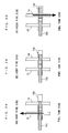
- the solenoid actuator 15a is controlled by a control input Upf, described in detail hereinafter, from the ECU 2 to drive a valve element 15c of the spool valve mechanism 15b such that the valve element 15c is moved between a pressure increasing position shown in FIG. 2A, a pressure holding position shown in FIG. 2B, and a pressure decreasing position shown in FIG. 2C.
- the valve element 15c opens the fuel supply passage 12 and closes the fuel return passage 14, whereby the fuel pressure Pf is increased.
- the valve element 15c closes the fuel supply passage 12 and opens the fuel return passage 14 whereby the fuel pressure Pf is decreased.
- the solenoid control valve 15 is controlled to the pressure holding position, the fuel supply passage 12 and the fuel return passage 14 are both closed by the valve element 15c whereby the fuel pressure Pf is held at the current value.
- the position of the valve element 15c of the solenoid control valve 15 is controlled by the ECU 2, whereby the fuel pressure Pf is controlled as described hereinafter.
- the fuel pressure Pf varies toward a target fuel pressure Pf_cmd in a relatively stable manner. That is, the fuel pressure Pf can be controlled with a high resolution.
- the pressure decreasing control is performed, even if the opening of the fuel return passage 14 is controlled to be small by the solenoid control valve 15, due to a structural characteristic in which the pressure in the fuel return passage 14 at a location downstream of the solenoid control valve 15 is far lower than pressure in the fuel chamber 13a and a structural characteristic of the spool valve mechanism 15b, at the instant the fuel return passage 14 is opened, the fuel pressure Pf temporarily undershoots the target fuel pressure Pf_cmd. In other words, the nonlinearities under the fuel pressure control temporarily becomes very strong, causing degradation of the resolution of fuel pressure control. As described above, when the fuel pressure Pf of the fuel supply system 10 is controlled, due to the structural characteristics thereof, there exist a control region in which nonlinearities are temporarily very strongly exhibited and a control region in which the nonlinearities are hardly exhibited.
- crank angle sensor 21 is comprised of a magnet rotor and an MRE pickup, and delivers a CRK signal, which is a pulse signal, to the ECU 2 along with rotation of the crankshaft of the engine 3.
- a CRK signal which is a pulse signal
- Each pulse of the CRK signal is generated whenever the crankshaft rotates through a predetermined crank angle (e.g. 10°), and the ECU 2 calculates rotational speed NE of the engine 3 (hereinafter referred to as "the engine speed NE”) based on the CRK signal.
- the accelerator pedal opening sensor 22 detects an amount of operation, i.e. a stepped-on amount (hereinafter referred to as "the accelerator pedal opening") AP of an accelerator pedal, not shown, of a vehicle on which the engine 3 is installed, and delivers a signal indicative of the detected accelerator pedal opening AP to the ECU 2.
- the IG ⁇ SW 23 is turned on and off by operation of an ignition key, not shown, and delivers a signal indicative of its ON/OFF state to the ECU 2.
- the ECU 2 is implemented by a microcomputer including a CPU, a RAM, a ROM, and an I/O interface, none of which are shown.
- the ECU 2 controls the fuel pressure Pf via the solenoid valve 15 based on the detection signals delivered from the above-mentioned sensors 20 to 22 and the output signal from the IG ⁇ SW 23. Further, the ECU 2 carries out fuel injection control via the fuel injection valves 9, and performs ignition timing control via an ignition plug, not shown.
- the ECU 2 corresponds to target value-setting means, first control input-calculating means, second control input-calculating means, control input-selecting means, central value-setting means, amplitude setting means, and disturbance estimate-calculating means.
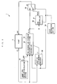
- the controller 1 is configured to control the fuel pressure Pf as the control amount by inputting the control input Upf to a plant 4.
- the plant 4 corresponds to a system including the fuel supply system 10.
- the controller 1 is comprised of a target fuel pressure-calculating section 30, a two-degree-of-freedom response-specifying controller 40, an adaptive disturbance observer 50, a DSM controller 60, a state determining section 70, and a control input-selecting section 80, which are implemented by the ECU 2.
- the target fuel pressure-calculating section 30 corresponds to the target value-setting means, the two-degree-of-freedom response-specifying controller 40 to the first control input-calculating means, the adaptive disturbance observer 50 to the disturbance estimate-calculating means, the DSM controller 60 to the second control input-calculating means, and the control input-selecting section 80 to the control input-selecting means.
- the target fuel pressure-calculating section 30 calculates the target fuel pressure Pf_cmd (target value) e.g. by map retrieval, described hereinafter.
- the two-degree-of-freedom response-specifying controller 40 calculates the first control input Rsld based on the target fuel pressure Pf_cmd, the fuel pressure Pf, and the like, with a target value filter-type two-degree-of-freedom response-specifying control algorithm expressed by the following equations (1) to (6):
- Pf_cmd_f ( k ) ⁇ R ⁇ Pf_cmd_f ( k ⁇ 1 ) + ( 1 + R ) ⁇ Pf_cmd ( k )
- R sld ( k ) R eq ( k ) + R rch ( k )
- R eq ( k ) 1 b 1 ⁇ ( 1 ⁇ a 1 ⁇ S ) ⁇ P f ( k ) + ( S ⁇ a 2 ) ⁇ P f ( k ⁇ 1 ) ⁇ b 2 ⁇ R sld ( k ⁇ 1 ) ⁇ c
- each piece of discrete data with the symbol (k) is data sampled or calculated in timing synchronous with a predetermined control period ⁇ T, referred to hereinafter, and the symbol k represents a position in the sequence of sampling or calculating cycles.
- the symbol k indicates that a value therewith is a value sampled or calculated at the current control period
- the symbol k-1 indicates that a value therewith is a value sampled or calculated at the immediately preceding control period.
- a filtered value Pf_cmd_f of the target fuel pressure is calculated with a first-order lag low-pass filter algorithm expressed by the equation (1).
- the symbol R represents a target value filter-setting parameter.
- the target value filter-setting parameter is set to a value satisfying the relationship of -1 ⁇ R ⁇ 0.
- the first control input Rsld is calculated with a response-specifying control algorithm (a sliding mode control algorithm or a back stepping control algorithm) expressed by the equations (2) to (6). More specifically, as shown in the equation (2), the first control input Rsld is calculated as the sum of an equivalent input Req and a reaching law input Rrch.
- the equivalent input Req is calculated using the equation (3).
- symbols a1, a2, b1, and b2 represent model parameters of a controlled object model, referred to hereinafter.
- the model parameters are set to predetermined fixed values, respectively.
- the symbol c1 in the equation (3) represents a disturbance estimate.
- the disturbance estimate c1 is calculated by the adaptive disturbance observer 50 as described hereinafter.
- the symbol S in the equation (3) represents a switching function-setting parameter.
- the switching function-setting parameter S is set to a value satisfying the relationship of -1 ⁇ R ⁇ S ⁇ 0.
- the reaching law input Rrch is calculated using the equation (4).
- the symbol Krch represents a predetermined reaching law gain
- the symbol 6 represents a switching function.
- the symbol Epf in the equation (5) represents a follow-up error, which is calculated by the equation (6).
- the follow-up speed of the fuel pressure Pf to the target fuel pressure Pf_cmd is set with a target value filter-type algorithm, and at the same time, the follow-up behavior of the fuel pressure to the target fuel pressure Pf_cmd is set with a sliding mode control algorithm. Therefore, it is possible to set the follow-up speed and the follow-up behavior separately, and also set both the follow-up speed and the follow-up behavior to respective higher levels than when the usual feedback control algorithm is employed.
- the first control input Rsld is calculated as a value having an excellent control characteristic in that it is capable of maintaining both the follow-up speed of the fuel pressure Pf to the target fuel pressure Pf_cmd and the follow-up behavior thereof at high levels, when the fuel supply system 10 is in the control region in which it hardly exhibits the nonlinearities.
- Pdof represent a predetermined identification gain
- e_dov represents an identification error calculated by the equation (9)
- Pf_hat in the equation (9) represents an identified value of the fuel pressure which is calculated by the equation (10).
- the state determining section 70 sets a F/C operation flag F_FC and a pressure decreasing control flag F_PDEC.
- the F/C operation flag F_FC indicates whether or not the conditions for F/C operation in which both the fuel injection and ignition of a mixture are stopped are satisfied. More specifically, the following F/C operation executing conditions (a) and (b) are both satisfied, the F/C operation flag is set to a value of 1, and otherwise set to 0.
- the difference between the fuel pressure Pf(k) and the target fuel pressure Pf_cmd(k) may be compared with the reference value EPF_TH, in place of the difference between the fuel pressure Pf(k) and the target fuel pressure Pf_cmd(k).
- the DSM controller 60 calculates the second control input Udsm by modulating the first control input Rsld, and is comprised of a central value calculating section 61, a differential component value-calculating section 62, an amplitude setting value-calculating section 63, a modulation section 64, and an adder 65.
- This central value-calculating section 61 calculates the central value Ucent of the amplitude of the second control input Udsm with a non-linear algorithm based on rate limits expressed by the following equations (11) to (15):
- U cent ( k ) U cent ( k ⁇ 1 ) + D u cent ( k )
- Ducent in the above equation (11) represents an amount of change in the central value Ucent, and is calculated by performing a limiting process on the difference Euc defined by the equation (12) using -EPS as a lower limit and +EPS as an upper limit.
- the value EPS is set to a predetermined positive value.
- Keu in the equation (14) represents a predetermined update gain, and is set to such a value as will satisfy the relationship of 0 ⁇ Keu ⁇ 1.
- the central value Ucent is calculated with a rate limit algorithm expressed by the equations (11) to (15), and hence is calculated as a value that will follow macroscopic changes in the first control input Rsld.
- the amount of change Ducent is calculated as a value obtained by multiplying the difference Euc by the update gain Keu satisfying the relationship of 0 ⁇ Keu ⁇ 1, and hence even when the first control input Rsld has suddenly changed, the central value Ucent is calculated as a value that gently follows the suddenly changed value of the first control input Rsld.
- the differential component value-calculating section 62 calculates a small differential component value UL and a large differential component value UH based on the first control input Rsld and the central value Ucent, by the following equations (16) to (22).
- the small differential component value UL is calculated by performing a limiting process on the difference Eu between the first control input and the central value, using -DUL as a lower limit value and +DUL as an upper limit value.
- This threshold value DUL is set to a predetermined positive value.
- the small differential component value UL is calculated as a value corresponding to a component when the first control input Rsld undergoes small changes within a range of the threshold value DUL with respect to the central value Ucent.
- the large differential component value UH is calculated as a value of 0 when the absolute value of the difference between the first control input Rsld and the central value Ucent does not exceed the absolute value of the threshold value DUL, and when the former exceeds the latter, the large differential component value UH is calculated as a value corresponding to the excess amount.
- the large differential component value UT is calculated as a value of 0, whereas when the first control input Rsld changes largely due to large changes in the target fuel pressure Pf_cmd, in other words, when the quick responsiveness of the control is demanded, it is calculated as a value that will properly reflect such a value of the first control input Rsld on the second control input Udsm.
- the amplitude-setting calculating section 63 calculates the amplitude setting value DUD based on the values of the two flags F_FC and F_PDEC set by the state determining section 70 described hereinabove, by the following equations (23) to (25).
- the amplitude setting value DUD determines the amplitude of a modulated value ULdsm, and more specifically, twofold of the amplitude setting value DUD, i.e. 2 ⁇ DUD corresponds to the amplitude of the modulated value ULdsm.
- DUDH, DUDL, and DUDM in the above equations (23) to (25) represent a predetermined F/C operation value, a pressure decreasing control value and a normal control value, respectively, and all these values are set to respective values not lower than the threshold value DUL.
- This is for the sake of securing the above-described excellent control characteristics of the first control input Rsld in the modulated value ULdsm, i.e. the second control input Udsm. That is, the characteristics of being capable of maintaining the follow-up speed of the fuel pressure Pf to the target fuel pressure Pf_cmd and the follow-up behavior at high levels, in the second control input Udsm.
- the two value DUDH and DUDL are set such that DUDH > DUDL holds. This is because during the F/C operation, the nonlinearities become stronger, and hence to more accurately execute the fuel injection control after resuming the fuel injection, it is necessary to perform the control with a higher resolution than when the pressure decreasing control is performed during the fuel injection operation. Therefore, by setting the amplitude of the modulated value ULdsm to a larger value, the resolution of the fuel pressure control is improved.
- the three values DUDH, DUDL, and DUDM are set such that the amplitude of the modulated value ULdsm, i.e. 2 ⁇ DUD is smaller than the range between the maximum value and the minimum value that the first control input Rsld can assume.
- the difference ⁇ d is calculated as the difference between the present value of the small differential component value UL and the immediately preceding value of the modulated value ULdsm.
- ⁇ d represents an integral value of the difference ⁇ d.
- the modulated value ULdsm is calculated as a value that is repeatedly inverted between the minimum value -DUD and the maximum value +DUD.
- the modulation section 64 calculates the modulated value ULdsm by modulating the small differential component value UL with an algorithm expressed by the above equations (26) to (30). Therefore, the when the first control input Rsld undergoes small changes, and hence there arises a small difference between the first control input Rsld and the central value Ucent, the modulated value ULdsm can be calculated as a value which is capable of compensating for the nonlinearities of the fuel supply system 10 while maintaining the above-described excellent control characteristics of the first control input Rsld. i.e. the characteristics of being capable of obtaining the follow-up speed of the fuel pressure Pf to the target fuel pressure Pf_cmd and the follow-up behavior at high levels.
- the adder 65 calculates the second control input Udsm by the following equation (31):
- U dsm ( k ) U L dsm ( k ) + U H ( k ) + U cent ( k )
- the DSM controller 60 calculates the second control input Udsm as a total sum of the modulated value ULdsm, the large differential component value UH, and the central value Ucent.
- the central value Ucent is calculated, as described above, as a value that will follow up macroscopic changes in the first control input Rsld
- the modulated value ULdsm is calculated, as described above, as a value that is capable of compensating for the nonlinearities of the fuel supply system 10 while maintaining the above-described excellent control characteristics of the first control input Rsld. i.e. the characteristic of being capable of obtaining the follow-up speed of the fuel pressure Pf to the target fuel pressure Pf_cmd and the follow-up behavior at high levels.
- the large differential component value UH is calculated as a value for causing the behavior of the first control input Rsld to be properly reflected on the second control input Udsm and securing the quick responsiveness of the control, under circumstances in which the quick responsiveness of the control is demanded, e.g. when the first control input Rsld changes largely due to large changes in the target fuel pressure Pf_cmd.
- the second control input Udsm calculated as a total sum of the three values ULdsm, UH, and Ucent is calculated as a value which has the above-described excellent control characteristics of the first control input Rsld, i.e. the characteristics of being capable of maintaining the follow-up speed of the fuel pressure Pf to the target fuel pressure Pf_cmd and the follow-up behavior at high levels, when the first control input Rsld undergoes small changes, and is at the same time capable of compensating for the nonlinearities of the fuel supply system 10 due to the fact that the modulated value ULdsm is modulated with the algorithm to which the ⁇ modulation algorithm is applied.
- the second control input Udsm is calculated as a value which is capable securing the quick responsiveness of the control by the large differential component value UH. Further, the second control input Udsm is calculated as a value the central value Ucent of which follows macroscopic changes in the first control input Rsld, and hence the amplitude thereof, i.e.
- the second control input Udsm is calculated as value which is capable of compensating for the nonlinearities of the fuel supply system 10 while securing the above-described excellent control characteristics of the first control input Rsld.
- the second control input Udsm may be calculated as a total sum of the modulated value ULdsm and the central value Ucent, by setting the large differential component value UH to a value of 0, depending on the necessity in control.
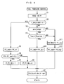
- the fuel pressure control process which is executed by the ECU 2, will be described with reference to FIG. 5.
- the fuel pressure control process is carried out in a predetermined cycle ⁇ T (5 msec in the present embodiment) so as to calculate the control input Upf described above.
- a value of the fuel pressure Pf stored in the RAM is read in.
- the value of the fuel pressure Pf is sampled. It should be noted that the value of the fuel pressure Pf is calculated by the moving average method, based on detection signal values from the fuel pressure sensor 20 in a fuel injection control process, not shown.
- step 2 it is determined whether or not an engine start flag F_ENGSTART is equal to 1.
- the engine start flag F_ENGSTART is set by determining in a determination process, not shown, from the engine speed NE and the output signal of the IG ⁇ SW 23 whether or not engine start control, i.e. cranking of the engine is being executed. More specifically, when the engine start control is being executed, the engine start flag F_ENGSTART is set to 1, and otherwise set to 0.
- step 3 the target fuel pressure Pf_cmd is set to a predetermined start-time value Pf_st.
- the predetermined start-time value Pf_st is set to a value (e.g. 2 MPa) that can ensure reduction of engine starting time and fuel spray suitable for engine start in a well balanced manner.
- a fuel pressure maintaining flag F_Pf_OK is set to 1 in a step 5 so as to indicate that the fuel pressure Pf is maintained high enough to perform appropriate fuel injection.
- control input Upf is calculated, described hereinafter, followed by terminating the present process.
- step 8 it is determined whether or not the accelerator pedal opening AP is smaller than a predetermined value APREF.
- the predetermined value APREF is used for determining whether the accelerator pedal is not being stepped on.
- the predetermined value APREF is set to a value (e.g. 1°) with reference to which it can be determined whether the accelerator pedal is not being stepped on.
- step 8 If the answer to the question of the step 8 is affirmative (YES), i.e. if the accelerator pedal is not being stepped on, the process proceeds to a step 9, wherein it is determined whether or not the count Tcat of a catalyst warm-up timer is smaller than a predetermined value Tcatlmt (e.g. 30 seconds).
- This catalyst warm-up timer which is used to count an execution time period of a catalyst warm-up control process, is formed by a upcount timer.
- the catalyst warm-up control process is executed so as to quickly activate a catalyst, not shown, in a catalyst device, not shown, provided in an exhaust pipe, not shown, of the engine 3.
- step 10 If the answer to the question of the step 9 is affirmative (YES), it is judged that the catalyst warm-up control is to be executed, and the process proceeds to a step 10, wherein the target fuel pressure Pf_cmd is set to a predetermined catalyst warm-up control value Pf_ast.
- This predetermined catalyst warm-up control value Pf_ast is preset to a value (e.g. 20 MPa) of the fuel pressure Pf that can maintain a stable combustion state during execution of ignition timing retard control in the catalyst warm-up control.
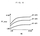
- step 8 or 9 if the answer to the question of the step 8 or 9 is negative (NO), i.e. if the accelerator pedal is being stepped on or Tcat ⁇ Tcatlmt holds when the engine start control is not being executed, the process proceeds to a step 11, wherein a normal operation value Pf_map is calculated by searching a map shown in FIG. 6 according to the engine speed NE and the accelerator pedal opening AP.
- reference symbols AP1 to AP3 represent predetermined values of the accelerator pedal opening AP in the relationship of AP1 ⁇ AP2 ⁇ AP3.
- the normal operation value Pf_map is set to a larger value as the engine speed NE is higher or the accelerator pedal opening AP is larger. This is because as the engine speed NE is higher or the accelerator pedal opening AP is larger, the output demanded of the engine 3 is larger, and therefore a higher fuel pressure Pf is demanded.
- the target fuel pressure Pf_cmd is set to the normal operation value Pf_map. Then, the control input Upf is calculated in the step 7, followed by terminating the present process.
- the first control input Rsld is calculated by the aforementioned equations (1) to (6) and (8) to (10).
- step 21 it is determined whether the F/C operation flag F_FC is equal to 1. If the answer to this question is affirmative (YES), i.e. if the conditions for executing the F/C operation are satisfied, the process proceeds to a step 22, wherein the amplitude setting value DUD is set to the F/C operation value DUDH. Then, in a step 23, a second control input selection flag F_DSM is set to 1 so as to indicate that the control region is in a region in which the second control input Udsm should be selected as the control input Upf.
- step 24 it is determined whether or not the pressure decreasing control flag F_PDEC is equal to 1. If the answer to this question is affirmative (YES), i.e. if the conditions for executing the pressure decreasing control are satisfied, the process proceeds to a step 25, wherein the amplitude setting value DUD is set to a pressure decreasing control value DUDL. Then, in the step 23, the second control input selection flag F_DSM is set to 1.
- step 24 determines whether the fuel supply system 10 is in a control region in which the first control input Rsld should be selected as the control input Upf.
- a step 28 following the step 23 or the step 27 the central value Ucent is calculated by the aforementioned equations (11) to (15). Then, the process proceeds to a step 29, wherein the large differential component value UH and the small differential component value UL are calculated by the aforementioned equations (16) to (22).
- the difference ⁇ d is calculated by the aforementioned equation (26).
- the integral value ⁇ d is calculated by the aforementioned equation (27).
- a step 32 it is determined whether or not the integral value ⁇ d calculated in the step 30 is not smaller than a value of 0. If the answer to this question is affirmative (YES), the modulated value ULdsm is set to DUD in a step 33, whereas if it is negative (NO), the modulated value ULdsm is set to -DUD in a step 34.
- the second control input Udsm is set to the sum of the modulated value ULdsm, the large differential component value UH, and the central value Ucent, calculated as described above.
- step 36 it is determined whether or not the second control selection flag F_DSM is equal to 1. If the answer to this question is affirmative (YES), the process proceeds to a step 37, wherein the control input Upf is set to the second control input Udsm. On the other hand, if the answer to this question is negative (NO), the process proceeds to a step 38, wherein the control input Upf is set to the first control input Rsld. After calculating the control input Upf as described above, the present process is terminated.
- FIG. 8 shows results of the control when the controller 1 according to the present embodiment executed the pressure decreasing control while holding the target fuel pressure Pf_cmd at a fixed value.
- FIG. 9 shows results of control the fuel pressure Pf using the first control input Rsld as the control input Upf in executing the pressure decreasing control, by way of Comparative Example.
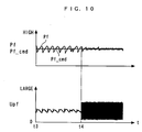
- FIG. 10 is a timing diagram showing an example of results of fuel pressure control during fuel cut operation, in which the control input Upf is switched from the first control input Rsld to the second control input Udsm at a time point t4.
- the pressure increasing control the pressure-increasing operation is constantly executed during operation of the engine 3 since the high-pressure pump 17 is connected to the crankshaft, and the operation for delivery of the fuel pressure increased in pressure into the delivery pipe 13 is intermittently executed since the high-pressure pump is of a volume type.
- the pressure increasing control and the pressure decreasing control are repeatedly alternately executed without the fuel pressure Pf converging to the target fuel pressure Pf_cmd.
- the fuel pressure Pf is controlled to a state substantially converged to the target fuel pressure Pf_cmd, from which it is understood that the nonlinearities of the fuel supply system 10 are properly compensated for, and the high-level resolution of the fuel pressure control can be secured.
- the first control input Rsld is calculated
- the second control input Udsm is calculated by modulating the first control input Rsld with the algorithm [equations (11) to (31)] to which is applied the ⁇ modulation algorithm. Then, when the fuel pressure Pf is controlled during F/C operation of the engine 3 or when the fuel pressure Pf is decreased during fuel supply operation, the second control input Udsm is selected as the control input Upf, whereas when the fuel pressure Pf is controlled to not to be decreased during fuel supply operation of the engine 3, the first control input Rsld is selected as the control input Upf.
- the first control input Rsld is calculated with the target value filter-type two-degree-of-freedom control algorithm as a combination of the target value filter-type algorithm and the response-specifying control algorithm. Therefore, through the use of the first control input Rsld, the target value filter-type algorithm makes it possible to set the converging speed of the fuel pressure Pf to the target fuel pressure Pf_cmd to a proper value, and separately therefrom, the response-specifying control algorithm makes it possible to properly set the converging behavior of the fuel pressure Pf to the target fuel pressure Pf_cmd.
- the converging behavior and the converging speed of the fuel pressure Pf to the target fuel pressure Pf_cmd can be properly set independently of each other.
- the use of the first control input Rsld thus calculated makes it possible to maintain both the converging speed of the fuel pressure Pf to the target fuel pressure Pf_cmd and the converging behavior at high levels, insofar as the fuel supply system 10 is in the control region in which it hardly exhibits the nonlinearities thereof.
- the first control input Rsld is selected as the control input Upf, whereby the follow-up speed of the fuel pressure Pf to the target fuel pressure Pf_cmd and the follow-up behavior can be both maintained at high levels.
- the fuel pressure Pf under the conditions of the sensitivity of the fuel pressure Pf to the control input Upf being reduced, it is possible to cause the fuel pressure Pf to converge to the target fuel pressure Pf_cmd while avoiding a state in which the amplitude of the control input Upf is reflected on the fuel pressure Pf in a noise-like fashion when the fuel supply system 10 is in the control region in which it hardly exhibits the nonlinearities, which would otherwise be caused when the second control input Udsm is selected as the control input Upf.
- the resolution and accuracy of the fuel pressure control can be improved compared with the case of the second control input Udsm being selected as the control input Upf in the control region in which the fuel supply system 10 hardly exhibits the nonlinearities.
- the second control input Udsm is selected as the control input Upf.
- the second control input Udsm is calculated as a value which has the above-described excellent control characteristics of the first control input Rsld, i.e.
- the central value Ucent of the second control input Udsm is calculated as a value following macroscopic changes in the first control input Rsld, compared with the conventional cases where the central value of the amplitude of the modulated control input does not change, it is possible to set the amplitude of the second control input Udsm to a smaller value. As a result, even when the first control input Rsld is large in the range of change, it is possible to secure the resolution and accuracy of the control at high levels.
- the amount of change Ducent of the central value Ucent is calculated as a value obtained by multiplying the difference Euc by the update gain Keu which satisfies the relationship of 0 ⁇ Keu ⁇ 1, when -EPS ⁇ Euc ⁇ EPS holds, and hence even when the first control input Rsld has suddenly changed, it is calculated as a value which gently follows the changed value of the first control input Rsld. As a result, at the start of decreasing the pressure, it is possible to suppress the fuel pressure from undershooting the target fuel pressure Pf_cmd.
- the amplitude setting value DUD for setting the amplitude of the second control input Udsm is set to the value DUDH which is larger than when the fuel pressure Pf is controlled to be decreased during fuel supply operation of the engine 3. Therefore, the amplitude of the modulated value ULdsm is set to a larger value than when the pressure decreasing control is executed during fuel supply operation. This makes it possible to improve the resolution of the fuel pressure control, and thereby accurately execute the fuel injection control upon resuming the fuel injection. As a result, it is possible to improve the accuracy of the air-fuel ratio control.
- the algorithm for calculating the modulated value ULdsm there is employed the algorithm to which the ⁇ modulation algorithm is applied. Therefore, due to the characteristics of the ⁇ modulation algorithm, as the small differential component value UL becomes closer to a value of 0, in other words, as the first control input Rsld becomes less changed when the fuel pressure Pf is close to the target fuel pressure Pf_cmd, the inverting frequency of the second control input Udsm becomes higher.
- the control algorithm in which the integral value of the difference between the fuel pressure Pf and the target fuel pressure Pf_cmd is used for disturbance compensation as the algorithm for calculating the first control input Rsld, if the fuel supply system 10 receives a disturbance, due to the disturbance compensation effect of the integral value, the difference between the fuel pressure Pf and the target fuel pressure Pf_cmd exhibits an oscillatory swing-back behavior or temporarily becomes too large.
- the disturbance estimate for compensating for the disturbance received by the fuel supply system 10 is calculated based on the fuel pressure Pf and the first control input Rsld with the estimation algorithm, and the first control input Rsld is calculated based on the disturbance estimate with the two-degree-of-freedom response-specifying control algorithm.
- the fuel supply system 10 receives a disturbance, differently from the case where the integral value of the difference between the fuel pressure Pf and the target fuel pressure Pf_cmd is used, it is possible to compensate for the influence of the disturbance while preventing the difference between the fuel pressure Pf and the target fuel pressure Pf_cmd from exhibiting the oscillatory swing-back behavior or becoming too large, thereby causing the fuel pressure Pf to speedily converge to the target fuel pressure Pf_cmd.
- the algorithm for calculating the second control input Udsm by modulating the first control input Rsld the algorithm [equations (11) to (31)] to which the ⁇ modulation algorithm is applied is used by way of example, this is not limitative, but any suitable algorithm may be employed insofar as it is capable of calculating the second control input Udsm by modulating the first control input Rsld.
- the algorithm for modulating the first control input Rsld there may be employed a PWM (Pulse Width Modulation) algorithm or an algorithm which modulates the first control input Rsld by dithering.
- the inverting frequency of the second control input Udsm becomes higher, so that compared with the case where the second control input Udsm modulated by the PWM or dithering whose inverting frequency is fixed, it is possible to improve the convergence of the fuel pressure Pf to the target fuel pressure Pf_cmd.
- the inverting frequency of the second control input Udsm becomes higher, so that compared with the case where the second control input Udsm modulated by the PWM or dithering whose inverting frequency is fixed, it is possible to improve the convergence of the fuel pressure Pf to the target fuel pressure Pf_cmd.
- the controller according to the present invention is applied to the fuel supply system 10 as the fluid circuit system or the plant, by way of example, this is not limitative, but the present invention can be applied to various fluid circuit systems and plants which include a control region in which nonlinearities are temporarily very strongly exhibited and a control region in which the nonlinearities are hardly exhibited.
- a controller 1 which controls fuel pressure Pf of a fuel supply system 10 includes an ECU 2.
- the ECU 2 sets a target fuel pressure Pf_cmd, calculates a first control input Rsld for causing the fuel pressure Pf to converge to the target fuel pressure Pf_cmd, with equations (1) to (6), modulates the first control input Rsld with equations (11) to (31) to thereby calculate a second control input Udsm, and depending on whether or not during fuel-cut operation or pressure decreasing control, selects one of the first and second control inputs Rsld and Udsm as the control input Upf.
Landscapes
- Engineering & Computer Science (AREA)
- Chemical & Material Sciences (AREA)
- Combustion & Propulsion (AREA)
- Mechanical Engineering (AREA)
- General Engineering & Computer Science (AREA)
- Evolutionary Computation (AREA)
- Artificial Intelligence (AREA)
- Computer Vision & Pattern Recognition (AREA)
- Health & Medical Sciences (AREA)
- Medical Informatics (AREA)
- Software Systems (AREA)
- Physics & Mathematics (AREA)
- General Physics & Mathematics (AREA)
- Automation & Control Theory (AREA)
- Electrical Control Of Air Or Fuel Supplied To Internal-Combustion Engine (AREA)
- Feedback Control In General (AREA)
- Combined Controls Of Internal Combustion Engines (AREA)
Abstract
Description
- The present invention relates to a controller for controlling the control amount of a plant that has nonlinearities, such as hysteresis and dead zone.
- A controller of the above-mentioned kind has already been proposed by the present assignee as disclosed in
Japanese Laid-Open Patent Publication (Kokai) No. 2005-63003 - Further, the DSM controller calculates the control input to the variable cam phase mechanism, by modulating the calculated SLD control input with an algorithm to which is applied a ΔΣ modulation algorithm, such that the control input is frequently inverted with a predetermined amplitude with respect to a predetermined value as the center. As a result, even when controlling the cam phase via the variable cam phase mechanism having nonlinearities, it is possible to control the cam phase by the control input frequently repeating the invention such that the cam phase is caused to converge to the target value while compensating for the nonlinearities. This makes it possible to control the cam phase in a fine-grained manner, and maintain both the resolution and the control accuracy of cam phase control at high levels.
- Assuming that the controller as disclosed in
Japanese Laid-Open Patent Publication (Kokai) No. 2005-63003 - It is an object of the present invention to provide a controller which is capable of improving the resolution and accuracy of control even when controlling a plant including a control region in which nonlinearities are temporarily very strongly exhibited and a control region in which the nonlinearities are hardly exhibited.
- To attain the above object, in a first aspect of the present invention, there is provided a controller that controls a control amount of a plant by a control input, comprising control amount-detecting means for detecting the control amount, target value-setting means for setting a target value as a target of the control amount, first control input-calculating means for calculating a first control input for controlling the detected control amount such that the detected control amount is caused to converge to the set target value, with a predetermined control algorithm, second control input-calculating means for calculating a second control input by modulating the first control input with an algorithm to which is applied a predetermined modulation algorithm, and control input-selecting means for selecting one of the first control input and the second control input as the control input, depending on conditions of the plant.
- With the configuration of the controller according to the first aspect of the present invention, the first control input for controlling the control amount such that the control amount is caused to converge to the target value is calculated with a predetermined control algorithm, and the second control input is calculated by modulating the first control input with an algorithm to which is applied a predetermined modulation algorithm. Further, depending on the conditions of the plant, one of the first control input and the second control input is selected. Therefore, in the case of the plant including a control region in which nonlinearities are temporarily very strongly exhibited, and a control region in which the nonlinearities are hardly exhibited, when the plant is in the control region in which the nonlinearities are exhibited, the second control input is selected as the control input, whereby it is possible to cause the control amount to converge to the target value while compensating for the strong nonlinearities of the plant. As a result, compared with the case of selecting the first control input as the control input in the control region in which the nonlinearities are exhibited, it is possible to control the control amount in a more finely-grained manner and improve the resolution and accuracy of the control.
- On the other hand, when the plant is in the control region in which the nonlinearities are hardly exhibited, by selecting the first control input before the modulation, as the control input, it is possible to cause the control amount to converge to the target value while avoiding a state in which the amplitude of the control input is reflected on the control amount in a noise-like fashion, which can be caused when the second control input having such an amplitude as can compensate for the nonlinearities in the control region in which the fluid circuit system exhibits the nonlinearities is selected, under the conditions of the sensitivity of the control amount to the control input being reduced. As a result, it is possible to control the control amount in a more finely-grained manner compared with the case of the second control input being selected as the control input in the control region in which the plant hardly exhibits the nonlinearities, to thereby improve the resolution and accuracy of the control. As described above, both in the control region in which the plant temporarily very strongly exhibits the nonlinearities and the control region in which the plant hardly exhibits the nonlinearities, it is possible to improve the resolution and accuracy of the control (it should be noted that the term "calculate" used in the present specification as in "calculating a first control input" and "calculates a second control input" is not limited to computation by a program but includes generating electric signals indicative these, by hardware.
- Preferably, the second control input-calculating means comprises central value-setting means for setting a central value as a center of an amplitude of the second control input according to the first control input, and amplitude setting means for setting the amplitude of the second control input to a value smaller than a range between a maximum value and a minimum value that the first control input can assume.
- As described above, in the case of the plant including a control region in which nonlinearities are temporarily very strongly exhibited, and a control region in which the nonlinearities are hardly exhibited, when the plant is in the control region where the nonlinearities are exhibited, there can occur a state in which the control amount largely deviates from the target value, and hence the range between the maximum value and the minimum value that the first control input can assume becomes considerably large. Therefore, if the amplitude of the second control input is set to a value large enough to cover the range between the maximum value and the minimum value that the first control input can assume, the large amplitude of the second control input is reflected on the control amount in a noise-like fashion, which can degrade the resolution and accuracy of the control. In contrast, with the configuration of the preferred embodiment, the central value as a center of the amplitude of the second control input is set according to the first control input, and hence even if the range between the maximum value and the minimum value that the first control input can assume is large, only by setting the amplitude of the second control input to such a value as can cover the first control input at the control timing, which is smaller than a value for covering the entire range of the first control input, it is possible to compensate for the nonlinearities of the plant while securing the capability of the first control input for converging control amount to the target value. Thus, the strong nonlinearities of the plant can be properly compensated for while setting the amplitude of the second control input to a smaller value than when the entire range of the first control input is covered, whereby it is possible to further improve the resolution and accuracy of the control.
- Preferably, the predetermined control algorithm is an algorithm to which is applied a target value filter-type two-degree-of-freedom control algorithm as a combination of a predetermined target value filter-type algorithm and a predetermined response-specifying control algorithm.
- With the configuration of this preferred embodiment, the first control input is calculated with an algorithm to which is applied the target value filter-type two-degree-of-freedom control algorithm as a combination of a predetermined target value filter-type algorithm and a predetermined response-specifying control algorithm. Therefore, through the use of the first control input, the target value filter-type algorithm makes it possible to set the converging speed of the control amount to the target value to a proper value, and separately therefrom, the predetermined response-specifying control algorithm makes it possible to properly set the converging behavior of the control amount to the target value. In short, in the calculation of the first control input, the converging behavior of the control amount to the target value and the converging speed at which the deviation between the control amount and the control input converges to a value of 0 can be properly set independently of each other. The use of the first control input thus calculated makes it possible to improve both the converging behavior of the control amount to the target value and the converging speed at which the difference between the control amount and the target value converges to a value of 0, compared with the case in which the first control input is calculated with a general feedback control algorithm. As a result, it is possible to further improve the control accuracy.
- Preferably, the predetermined modulation algorithm is one of a ΔΣ modulation algorithm, a ΣΔ modulation algorithm, and a Δ modulation algorithm.
- With the configuration of this preferred embodiment, the second control input is calculated by modulating the first control input with an algorithm to which is applied one of the ΔΣ modulation algorithm, the ΣΔ modulation algorithm, and the Δ modulation algorithm. In this case, all of the ΔΣ modulation algorithm, the ΣΔ modulation algorithm, and the Δ modulation algorithm have a characteristic that as the value input to these algorithm becomes closer to a value of 0, the inverting frequency of the value calculated with any of these algorithm becomes higher. On the other hand, the first control input is a value for controlling the control amount such that the control amount is caused to converge to the target value, and hence the first control input is less changed as the control amount becomes closer to the target value. Therefore, in the algorithm to which is applied one of the ΔΣ modulation algorithm, the ΣΔ modulation algorithm, and the Δ modulation algorithm, by configuring the algorithm such that if the first control input ceases to be changed, the value input to the one of them becomes closer to a value of 0, it is possible to calculate the control input such that the inventing frequency of the second control input becomes higher as the control amount becomes closer to the target value. As a result, compared with the case where the second control input is calculated using PWM or dithering in which the inverting frequency is fixed, it is possible to improve the convergence of the control amount to the target value.
- Preferably, the controller further comprises disturbance estimate-calculating means for calculating a disturbance estimate for compensating for a disturbance which the plant receives, based on the control amount and the first control input, with a predetermined estimation algorithm, and the first control input-calculating means calculates the first control input based on the calculated disturbance estimate with the predetermined control algorithm.
- When the control algorithm using an integral value of the difference between the control amount and the target value for disturbance compensation is used as the algorithm for calculating the first control input, there is a fear that when the plant receives a disturbance, due to the disturbance compensation effect of the integral value, the difference between the control amount and the target value exhibits an oscillatory swing-back behavior, or temporarily becomes too large. In contrast, with the configuration of this preferred embodiment, the disturbance estimate for compensating for the disturbance received by the plant is calculated based on the control amount and the first control input with a predetermined estimation algorithm, and the first control input is calculated based on the disturbance estimate with a predetermined control algorithm. Therefore, when the plant receives a disturbance, differently from the case where the integral value of the difference between the control amount and the target value is used, it is possible to compensate for the influence of the disturbance while preventing the difference between the control amount and the target value from exhibiting the oscillatory swing-back behavior or becoming too large, thereby making it possible to cause the control amount to speedily converge to the target value.
- To attain the above object, in a second aspect of the present invention, there is provided a controller that controls fluid pressure of a fluid circuit system in which the fluid pressure is increased and decreased by opening and closing of a pressure increasing passage and a pressure decreasing passage, comprising a valve that opens and closes the pressure increasing passage and the pressure decreasing passage, an actuator that actuates the valve, fluid pressure-detecting means for detecting the fluid pressure, target value-setting means for setting a target value as a target of the fluid pressure, first control input-calculating means for calculating a first control input for controlling the detected fluid pressure such that the detected fluid pressure is caused to converge to the set target value, with a predetermined control algorithm, second control input-calculating means for calculating a second control input by modulating the first control input with an algorithm to which is applied a predetermined modulation algorithm, and control input-selecting means for selecting one of the first control input and the second control input as the control input to the actuator, depending on conditions of the fluid circuit system.
- With the configuration of this controller, the first control input for controlling the control amount such that the fluid pressure is caused to converge to the target value is calculated with a predetermined control algorithm, and the second control input is calculated by modulating the first control input with an algorithm to which is applied a predetermined modulation algorithm. Further, depending on the conditions of the fluid circuit system, one of the first control input and the second control input is selected. On the other hand, in the fluid circuit system in which the fluid pressure increases and decreases due to opening and closing of the pressure increasing passage and the pressure decreasing passage, if the control pressure is controlled by actuating the valve for opening and closing the pressure increasing passage and the pressure decreasing passage, there are cases in which there occur a control region in which nonlinearities are temporarily very strongly exhibited, and a control region in which the nonlinearities are hardly exhibited. Therefore, when the fluid circuit system is in the control region in which the nonlinearities are exhibited, the second control input is selected as the control input, whereby it is possible to cause the fluid pressure to converge to the target value while compensating for the strong nonlinearities. As a result, compared with the case of selecting the first control input as the control input in the control region in which the nonlinearities are exhibited, it is possible to improve the resolution and accuracy of the fluid pressure control.
- On the other hand, when the fluid circuit system is in the control region in which the nonlinearities are hardly exhibited, by selecting the first control input before the modulation, as the control input, it is possible to cause the fluid pressure to converge to the target value while avoiding a state in which the amplitude of the control input is reflected on the fluid pressure in a noise-like fashion, which can be caused when the second control input having such an amplitude as can compensate for the nonlinearities in the control region in which the fluid circuit system exhibits the nonlinearities is selected. As a result, it is possible to improve the resolution and accuracy of the fluid pressure control compared with the case of the second control input being selected as the control input in the control region in which the plant hardly exhibits the nonlinearities. As described above, both in the control region in which the plant temporarily very strongly exhibits the nonlinearities and the control region in which the plant hardly exhibits the nonlinearities, it is possible to improve the resolution and accuracy of the control.
- Preferably, the second control input-calculating means comprises central value-setting means for setting a central value as a center of an amplitude of the second control input according to the first control input, and amplitude setting means for setting the amplitude of the second control input to a value smaller than a range between a maximum value and a minimum value that the first control input can assume.
- As described above, when controlling the fluid pressure in the fluid circuit system including a control region in which nonlinearities are temporarily very strongly exhibited, and a control region in which the nonlinearities are hardly exhibited, if the fuel circuit system is in the control region where the nonlinearities are exhibited, the second control input is selected as the control input, if the amplitude of the second control input is set to a value large enough to cover the range between the maximum value and the minimum value that the first control input can assume, the large amplitude of the second control input is reflected on the fluid pressure in a noise-like fashion, which can degrade the resolution and accuracy of the fluid pressure control. In contrast, with the configuration of this preferred embodiment, the central value as a center of the amplitude of the second control input is set according to the first control input, and hence even if the range between the maximum value and the minimum value that the first control input can assume is large, only by setting the amplitude of the second control input to such a value as can cover the first control input at the control timing, which is smaller than a value for covering the entire range of the first control input, it is possible to compensate for the nonlinearities of the fluid circuit system while securing the capability of the first control input for converging fluid pressure to the target value. Thus, in the control region in which the fluid circuit system temporarily very strongly exhibits the nonlinearities, the strong nonlinearities can be properly compensated for while setting the amplitude of the second control input to a smaller value, whereby it is possible to further improve the resolution and accuracy of the fluid pressure control.
- Preferably, the predetermined control algorithm is an algorithm to which is applied a target value filter-type two-degree-of-freedom control algorithm as a combination of a predetermined target value filter-type algorithm and a predetermined response-specifying control algorithm.
- With the configuration of this preferred embodiment, the first control input is calculated with an algorithm to which is applied the target value filter-type two-degree-of-freedom control algorithm as a combination of a predetermined target value filter-type algorithm and a predetermined response-specifying control algorithm. Therefore, through the use of the first control input, the target value filter-type algorithm makes it possible to set the converging speed of the fluid pressure to the target value to a proper value, and separately therefrom, the predetermined response-specifying control algorithm makes it possible to properly set the converging behavior of the fluid pressure to the target value. In short, in the calculation of the first control input, the converging behavior and the converging speed of the fluid pressure to the target value can be properly set independently of each other. The use of the first control input thus calculated makes it possible to improve both the converging behavior of the fluid pressure to the target value and the converging speed, compared with the case in which the first control input is calculated with a general feedback control algorithm. As a result, it is possible to further improve the control accuracy.
- Preferably, the predetermined modulation algorithm is one of a ΔΣ modulation algorithm, a ΣΔ modulation algorithm, and a Δ modulation algorithm.
- With the configuration of this preferred embodiment, the second control input is calculated by modulating the first control input with an algorithm to which is applied one of the ΔΣ modulation algorithm, the ΣΔ modulation algorithm, and the Δ modulation algorithm. In this case, all of the ΔΣ modulation algorithm, the ΣΔ modulation algorithm, and the Δ modulation algorithm have a characteristic that as the value input to these algorithms becomes closer to a value of 0, the inverting frequency of the value calculated with any of these algorithm becomes higher. On the other hand, the first control input is a value for controlling the fluid pressure such that the fluid pressure is caused to converge to the target value, and hence the first control input is less changed as the fluid pressure is closer to the target value. Therefore, in the algorithm using one of the ΔΣ modulation algorithm, the ΣΔ modulation algorithm, and the Δ modulation algorithm, by configuring the algorithm such that if the first control input ceases to be changed, the value input to the one of the ΔΣ modulation algorithm, the ΣΔ modulation algorithm, and the Δ modulation algorithm becomes closer to a value of 0, it is possible to calculate the control input such that the inventing frequency of the second control input becomes higher as the fluid pressure becomes closer to the target value. As a result, compared with the case where the second control input is calculated using PWM or dithering in which the inverting frequency is fixed, it is possible to improve the convergence of the fluid pressure to the target value.
- Preferably, the controller further comprises disturbance estimate-calculating means for calculating a disturbance estimate for compensating for a disturbance which the fluid circuit system receives, based on the fluid pressure and the first control input, with a predetermined estimation algorithm, and the first control input-calculating means calculates the first control input based on the calculated disturbance estimate with the predetermined control algorithm.
- When the control algorithm using an integral value of the difference between the fluid pressure for disturbance compensation and the target value is used as the algorithm for calculating the first control input, there is a fear that when the fluid circuit system receives a disturbance, due to the disturbance compensation effect of the integral value, the difference between the fluid pressure and the target value exhibits an oscillatory swing-back behavior, or temporarily becomes too large. In contrast, with the configuration of this preferred embodiment, the disturbance estimate for compensating for the disturbance received by the fluid circuit system is calculated based on the fluid pressure and the first control input with a predetermined estimation algorithm, and the first control input is calculated based on the disturbance estimate with a predetermined control algorithm. Therefore, when the fluid circuit system receives a disturbance, differently from the case where the integral value of the difference between the fluid pressure and the target value is used, it is possible to compensate for the influence of the disturbance while preventing the difference between the fluid pressure and the target value from exhibiting the oscillatory swing-back behavior or becoming too large, thereby causing the fluid pressure to speedily converge to the target value.
- Preferably, the fluid circuit system is a fuel supply system that supplies fuel to an internal combustion engine, the fluid pressure being a fuel pressure in the fuel supply system, and the control input-selecting means selects the second control input as the control input, when the fuel pressure is controlled to be deceased.
- In the fuel supply system, when the fuel pressure is controlled to be decreased due to a higher value thereof than the target value, if the pressure decreasing passage is opened by the valve, the fuel at high pressure is suddenly released, so that even if the opening degree of the valve is set to a smaller value, the fuel pressure tends to temporarily largely undershoot the target value. In other words, the nonlinearities become temporarily very strong. Therefore, when the fuel pressure is controlled to be decreased, if the first control input is selected as the control input, such strong nonlinearities cannot be compensated for, which lowers the resolution and accuracy of the fuel pressure control. In contrast, with the configuration of the preferred embodiment, when the fuel pressure is controlled to be decreased, the second control input is selected, which makes it possible to compensate for the strong nonlinearities and avoid the occurrence of large undershooting. As a result, it is possible to improve the resolution and accuracy of the fuel pressure control.
- Preferably, the fluid circuit system is a fuel supply system that supplies fuel to an internal combustion engine, the fluid pressure being a fuel pressure in the fuel supply system, and the control input-selecting means selects the second control input as the control input, when fuel supply from the fuel supply system to the engine is interrupted.
- As described above, the fuel supply system tends to exhibit strong nonlinearities when the fuel pressure is controlled to be decreased, causing the fuel pressure to temporarily largely undershoot the target value. Therefore, if the first control input is selected as the control input when the fuel supply from the fuel supply system to the internal combustion engine is interrupted and the target value is set to a substantially fixed value, such strong nonlinearities cannot be compensated for, causing the undershooting during the pressure decreasing control. For recovery from this, the pressure increasing control is consecutively executed. In other words, the pressure increasing control and the pressure decreasing control are repeatedly executed, which results in a state where the fuel pressure does not converge to the target value. As a result, when the supply of fuel to the engine is resumed, it is impossible to supply the fuel at suitable fuel pressure, which degrades the accuracy of fuel supply control, causing degradation of the accuracy of air fuel ratio control. In contrast, with the configuration of this preferred embodiment, when the fuel supply to the engine from the fuel supply system is interrupted, the second control input is selected, which makes it possible to compensate fro the strong nonlinearities and avoid the occurrence of large undershooting, whereby the fuel pressure can be caused to converge to the target value. As a result, when the supply of the fuel to the engine is resumed, it is possible to supply the fuel at suitable fuel pressure, thereby making it possible to improve the accuracy of the air-fuel ratio control.
- The above and other objects, features, and advantages of the present invention will become more apparent from the following detailed description taken in conjunction with the accompanying drawings.
-
- FIG. 1 is a schematic diagram of a controller according to an embodiment of the present invention and a fuel supply system to which is applied the controller;
- FIGS. 2A to 2C are views showing operating states of a spool valve mechanism;
- FIG. 3 is a schematic block diagram of the controller;
- FIG. 4 is a schematic block diagram of a DSM controller;
- FIG. 5 is a flowchart showing a fuel pressure control process;
- FIG. 6 is a diagram showing an example of a map for use in the calculation of a normal operation value Pf_map;
- FIG. 7 is a flowchart showing a process for calculating the control input Upf;
- FIG. 8 is a timing diagram showing an example of results of pressure decreasing control of fuel pressure executed by the controller according to the present embodiment;
- FIG. 9 is a timing diagram showing results of fuel pressure control by Comparative Example; and
- FIG. 10 is a timing diagram showing an example of results of fuel pressure control during fuel cut operation, in which the control input Upf is switched from a first control input Rsld to a second control input Udsm.
- The present invention will now be described in detail with reference to the drawings showing preferred embodiments thereof. Referring first to FIG. 1, there is schematically shown the arrangement of a
fuel supply system 10 to which is applied acontroller 1 according to an embodiment of the present invention. As shown in FIG. 1, thecontroller 1 includes anECU 2 which carries out control processes, such as a fuel pressure control process, described in detail hereinafter. - The
fuel supply system 10 is applied to a straight type four-cylinder internal combustion engine 3 (hereinafter simply referred to as "theengine 3"), and supplies high-pressure fuel (gasoline) to fourfuel injection valves 9 during operation of theengine 3. Thefuel supply system 10 includes afuel tank 11, adelivery pipe 13 connected to thefuel tank 11 via afuel supply passage 12 and afuel return passage 14, and asolenoid control valve 15 for opening and closing thefuel supply passage 12 and thefuel return passage 14. It should be note that in the present embodiment, thefuel supply system 10 corresponds to a fluid circuit system and a fuel supply system, and thefuel supply passage 12 and thefuel return passage 14 corresponds to a pressure increasing passage and a pressure decreasing passage, respectively. - The
fuel supply passage 12 is provided with a low-pressure pump 16 and a high-pressure pump 17. The low-pressure pump 16 is an electric pump whose operation is controlled by theECU 2. The low-pressure pump 16 is constantly controlled during operation of theengine 3 to pressurize fuel within thefuel tank 11 to a predetermined pressure (e.g. 0.5 MPa) and deliver the pressurized fuel toward the high-pressure pump 17. - The high-
pressure pump 17 is of a volume type and is connected to a crankshaft, not shown. The high-pressure pump 17 further pressurizes the fuel from the low-pressure pump 16 in accordance with rotation of the crankshaft, and delivers the fuel toward thedelivery pipe 13. - The
delivery pipe 13 has an inner space formed as afuel chamber 13a for storing the fuel from the high-pressure pump 17 in a high-pressure state. The aforementioned fourfuel injection valves 9 and afuel pressure sensor 20 are mounted to thedelivery pipe 13, and when eachfuel injection valve 9 is opened, the fuel within thefuel chamber 13a is injected into a combustion chamber, not shown, of theengine 3. - The
fuel pressure sensor 20 is electrically connected to theECU 2, and detects a fuel pressure Pf within thefuel chamber 13a to output an electric signal indicative of the sensed fuel pressure Pf to theECU 2. It should be noted that in the present embodiment, thefuel pressure sensor 20 corresponds to control amount-detecting means and fluid pressure-detecting means, and the fuel pressure Pf corresponds to a control amount and fluid pressure. - The
solenoid control valve 15 is of a type formed by combining asolenoid actuator 15a and aspool valve mechanism 15b, and is connected to theECU 2. Thesolenoid actuator 15a is controlled by a control input Upf, described in detail hereinafter, from theECU 2 to drive avalve element 15c of thespool valve mechanism 15b such that thevalve element 15c is moved between a pressure increasing position shown in FIG. 2A, a pressure holding position shown in FIG. 2B, and a pressure decreasing position shown in FIG. 2C. - In the
fuel supply system 10, when thesolenoid control valve 15 is controlled to the pressure increasing position, thevalve element 15c opens thefuel supply passage 12 and closes thefuel return passage 14, whereby the fuel pressure Pf is increased. On the other hand, when thesolenoid control valve 15 is controlled to the pressure decreasing position, thevalve element 15c closes thefuel supply passage 12 and opens thefuel return passage 14 whereby the fuel pressure Pf is decreased. Further, when thesolenoid control valve 15 is controlled to the pressure holding position, thefuel supply passage 12 and thefuel return passage 14 are both closed by thevalve element 15c whereby the fuel pressure Pf is held at the current value. - With the above described arrangement, in the
fuel supply system 10, the position of thevalve element 15c of thesolenoid control valve 15 is controlled by theECU 2, whereby the fuel pressure Pf is controlled as described hereinafter. In this case, when the pressure increasing control is performed, since the inside of thefuel chamber 13a is at high pressure, the fuel pressure Pf varies toward a target fuel pressure Pf_cmd in a relatively stable manner. That is, the fuel pressure Pf can be controlled with a high resolution. - On the other, when the pressure decreasing control is performed, even if the opening of the
fuel return passage 14 is controlled to be small by thesolenoid control valve 15, due to a structural characteristic in which the pressure in thefuel return passage 14 at a location downstream of thesolenoid control valve 15 is far lower than pressure in thefuel chamber 13a and a structural characteristic of thespool valve mechanism 15b, at the instant thefuel return passage 14 is opened, the fuel pressure Pf temporarily undershoots the target fuel pressure Pf_cmd. In other words, the nonlinearities under the fuel pressure control temporarily becomes very strong, causing degradation of the resolution of fuel pressure control. As described above, when the fuel pressure Pf of thefuel supply system 10 is controlled, due to the structural characteristics thereof, there exist a control region in which nonlinearities are temporarily very strongly exhibited and a control region in which the nonlinearities are hardly exhibited. - Also connected to the
ECU 2 are acrank angle sensor 21, an acceleratorpedal opening sensor 22, and an ignition switch sensor (hereinafter referred to as "the IG * SW") 23. Thecrank angle sensor 21 is comprised of a magnet rotor and an MRE pickup, and delivers a CRK signal, which is a pulse signal, to theECU 2 along with rotation of the crankshaft of theengine 3. Each pulse of the CRK signal is generated whenever the crankshaft rotates through a predetermined crank angle (e.g. 10°), and theECU 2 calculates rotational speed NE of the engine 3 (hereinafter referred to as "the engine speed NE") based on the CRK signal. - Further, the accelerator
pedal opening sensor 22 detects an amount of operation, i.e. a stepped-on amount (hereinafter referred to as "the accelerator pedal opening") AP of an accelerator pedal, not shown, of a vehicle on which theengine 3 is installed, and delivers a signal indicative of the detected accelerator pedal opening AP to theECU 2. The IG·SW 23 is turned on and off by operation of an ignition key, not shown, and delivers a signal indicative of its ON/OFF state to theECU 2. - The
ECU 2 is implemented by a microcomputer including a CPU, a RAM, a ROM, and an I/O interface, none of which are shown. TheECU 2 controls the fuel pressure Pf via thesolenoid valve 15 based on the detection signals delivered from the above-mentionedsensors 20 to 22 and the output signal from the IG·SW 23. Further, theECU 2 carries out fuel injection control via thefuel injection valves 9, and performs ignition timing control via an ignition plug, not shown. - It should be noted that in the present embodiment, the
ECU 2 corresponds to target value-setting means, first control input-calculating means, second control input-calculating means, control input-selecting means, central value-setting means, amplitude setting means, and disturbance estimate-calculating means. - Next, the
controller 1 according to the present embodiment will be described with reference to FIG. 3. As shown in FIG. 3, thecontroller 1 is configured to control the fuel pressure Pf as the control amount by inputting the control input Upf to aplant 4. Theplant 4 corresponds to a system including thefuel supply system 10. - As shown in FIG. 3, the
controller 1 is comprised of a target fuel pressure-calculatingsection 30, a two-degree-of-freedom response-specifyingcontroller 40, anadaptive disturbance observer 50, aDSM controller 60, astate determining section 70, and a control input-selectingsection 80, which are implemented by theECU 2. In the present embodiment, the target fuel pressure-calculatingsection 30 corresponds to the target value-setting means, the two-degree-of-freedom response-specifyingcontroller 40 to the first control input-calculating means, theadaptive disturbance observer 50 to the disturbance estimate-calculating means, theDSM controller 60 to the second control input-calculating means, and the control input-selectingsection 80 to the control input-selecting means. - First, the target fuel pressure-calculating
section 30 calculates the target fuel pressure Pf_cmd (target value) e.g. by map retrieval, described hereinafter. - Also, the two-degree-of-freedom response-specifying controller 40 calculates the first control input Rsld based on the target fuel pressure Pf_cmd, the fuel pressure Pf, and the like, with a target value filter-type two-degree-of-freedom response-specifying control algorithm expressed by the following equations (1) to (6):





- In these equations (1) to (6), each piece of discrete data with the symbol (k) is data sampled or calculated in timing synchronous with a predetermined control period ΔT, referred to hereinafter, and the symbol k represents a position in the sequence of sampling or calculating cycles. For example, the symbol k indicates that a value therewith is a value sampled or calculated at the current control period, and the symbol k-1 indicates that a value therewith is a value sampled or calculated at the immediately preceding control period. This applies to discrete data in equations described hereinafter. It should be noted that in the following, the symbol (k) and the like are omitted when deemed appropriate.
- In the present control algorithm, first, a filtered value Pf_cmd_f of the target fuel pressure is calculated with a first-order lag low-pass filter algorithm expressed by the equation (1). In the equation (1), the symbol R represents a target value filter-setting parameter. The target value filter-setting parameter is set to a value satisfying the relationship of -1 < R < 0.
- Then, the first control input Rsld is calculated with a response-specifying control algorithm (a sliding mode control algorithm or a back stepping control algorithm) expressed by the equations (2) to (6). More specifically, as shown in the equation (2), the first control input Rsld is calculated as the sum of an equivalent input Req and a reaching law input Rrch. The equivalent input Req is calculated using the equation (3). In the equation (3), symbols a1, a2, b1, and b2 represent model parameters of a controlled object model, referred to hereinafter. The model parameters are set to predetermined fixed values, respectively. Further, the symbol c1 in the equation (3) represents a disturbance estimate. The disturbance estimate c1 is calculated by the
adaptive disturbance observer 50 as described hereinafter. The symbol S in the equation (3) represents a switching function-setting parameter. The switching function-setting parameter S is set to a value satisfying the relationship of -1 < R < S < 0. - The reaching law input Rrch is calculated using the equation (4). In the equation (4), the symbol Krch represents a predetermined reaching law gain, and the
symbol 6 represents a switching function. The symbol Epf in the equation (5) represents a follow-up error, which is calculated by the equation (6). - According to the control algorithm of the two-degree-of-freedom response-specifying
controller 40, the follow-up speed of the fuel pressure Pf to the target fuel pressure Pf_cmd is set with a target value filter-type algorithm, and at the same time, the follow-up behavior of the fuel pressure to the target fuel pressure Pf_cmd is set with a sliding mode control algorithm. Therefore, it is possible to set the follow-up speed and the follow-up behavior separately, and also set both the follow-up speed and the follow-up behavior to respective higher levels than when the usual feedback control algorithm is employed. That is, the first control input Rsld is calculated as a value having an excellent control characteristic in that it is capable of maintaining both the follow-up speed of the fuel pressure Pf to the target fuel pressure Pf_cmd and the follow-up behavior thereof at high levels, when thefuel supply system 10 is in the control region in which it hardly exhibits the nonlinearities. - The equations (1) to (6) are derived as follows: Assuming that the
plant 4 to be controlled is defined as a system to which the first control input Rsld is inputted as the control input, using the fuel pressure Pf as the control amount, and in which the disturbance estimate c1 represents a disturbance input, and this system is modeled into a discrete-time system model, the following equation (7) is obtained:
- When a target value filter-type two-degree-of-freedom response-specifying control theory is used based on the controlled object model obtained by discretizing the disturbance estimate c1 in the equation (7), such that the fuel pressure Pf converges to the target fuel pressure Pf_cmd, the equations (1) to (6) are derived.
- Next, a description will be given of the
adaptive disturbance observer 50. In theadaptive disturbance observer 50, the disturbance estimate c1 is calculated based on the fuel pressure Pf and the first control input Rsld, with the disturbance estimation algorithm expressed by the following equations (8) to (10):


- In the equation (8), Pdof represent a predetermined identification gain, and e_dov represents an identification error calculated by the equation (9). Pf_hat in the equation (9) represents an identified value of the fuel pressure which is calculated by the equation (10).
- Further, the
state determining section 70 sets a F/C operation flag F_FC and a pressure decreasing control flag F_PDEC. The F/C operation flag F_FC indicates whether or not the conditions for F/C operation in which both the fuel injection and ignition of a mixture are stopped are satisfied. More specifically, the following F/C operation executing conditions (a) and (b) are both satisfied, the F/C operation flag is set to a value of 1, and otherwise set to 0. - (a) Engine speed NE is not lower than a predetermined value.
- (b) Accelerator opening AP indicates a value representative of a non-stepped-on state of the accelerator pedal.
- On the other hand, the pressure decreasing control flag F_PDEC indicates whether or not conditions for executing the pressure decreasing control are satisfied, and is set according to the results of comparison between the aforementioned difference Epf (= Pf(k) - Pf_cmd_f(k-1)) and a predetermined reference value EPF_TH (e.g. 0.05 MPa). More specifically, the pressure decreasing control flag F_PDEC is set to 1 when Epf > EPF_TH holds, and to 0 when Epf ≦ EPF_TH holds. These two flags F_FC and F_PDEC are used, as described hereinafter, when the
DSM controller 60 determines an amplitude setting value DUD, and when the control input-selectingsection 80 selects the control input Upf. Further, when setting the pressure decreasing control flag F_PDEC, the difference between the fuel pressure Pf(k) and the target fuel pressure Pf_cmd(k) may be compared with the reference value EPF_TH, in place of the difference between the fuel pressure Pf(k) and the target fuel pressure Pf_cmd(k). - Next, a description will be given of the
DSM controller 60. TheDSM controller 60 calculates the second control input Udsm by modulating the first control input Rsld, and is comprised of a centralvalue calculating section 61, a differential component value-calculatingsection 62, an amplitude setting value-calculatingsection 63, amodulation section 64, and anadder 65. - This central value-calculating section 61 (central value-setting means) calculates the central value Ucent of the amplitude of the second control input Udsm with a non-linear algorithm based on rate limits expressed by the following equations (11) to (15):





- Ducent in the above equation (11) represents an amount of change in the central value Ucent, and is calculated by performing a limiting process on the difference Euc defined by the equation (12) using -EPS as a lower limit and +EPS as an upper limit. The value EPS is set to a predetermined positive value. Further, Keu in the equation (14) represents a predetermined update gain, and is set to such a value as will satisfy the relationship of 0 < Keu << 1.
- As described above, the central value Ucent is calculated with a rate limit algorithm expressed by the equations (11) to (15), and hence is calculated as a value that will follow macroscopic changes in the first control input Rsld. Particularly, as shown in the equation (14), when -EPS < Euc < EPS holds, the amount of change Ducent is calculated as a value obtained by multiplying the difference Euc by the update gain Keu satisfying the relationship of 0 < Keu << 1, and hence even when the first control input Rsld has suddenly changed, the central value Ucent is calculated as a value that gently follows the suddenly changed value of the first control input Rsld.
- On the other hand, the differential component value-calculating
section 62 calculates a small differential component value UL and a large differential component value UH based on the first control input Rsld and the central value Ucent, by the following equations (16) to (22).


- As shown in the above equations (16), (17), (19), and (21), the small differential component value UL is calculated by performing a limiting process on the difference Eu between the first control input and the central value, using -DUL as a lower limit value and +DUL as an upper limit value. This threshold value DUL is set to a predetermined positive value. Thus, the small differential component value UL is calculated as a value corresponding to a component when the first control input Rsld undergoes small changes within a range of the threshold value DUL with respect to the central value Ucent.
- Further, as shown in the equations (18), (20), and (22), the large differential component value UH is calculated as a value of 0 when the absolute value of the difference between the first control input Rsld and the central value Ucent does not exceed the absolute value of the threshold value DUL, and when the former exceeds the latter, the large differential component value UH is calculated as a value corresponding to the excess amount. More specifically, when the first control input Rsld undergoes small changes, the large differential component value UT is calculated as a value of 0, whereas when the first control input Rsld changes largely due to large changes in the target fuel pressure Pf_cmd, in other words, when the quick responsiveness of the control is demanded, it is calculated as a value that will properly reflect such a value of the first control input Rsld on the second control input Udsm.
- Further, the amplitude-setting calculating section 63 (amplitude setting means) calculates the amplitude setting value DUD based on the values of the two flags F_FC and F_PDEC set by the
state determining section 70 described hereinabove, by the following equations (23) to (25). The amplitude setting value DUD determines the amplitude of a modulated value ULdsm, and more specifically, twofold of the amplitude setting value DUD, i.e. 2 · DUD corresponds to the amplitude of the modulated value ULdsm.


- Now, DUDH, DUDL, and DUDM in the above equations (23) to (25) represent a predetermined F/C operation value, a pressure decreasing control value and a normal control value, respectively, and all these values are set to respective values not lower than the threshold value DUL. This is for the sake of securing the above-described excellent control characteristics of the first control input Rsld in the modulated value ULdsm, i.e. the second control input Udsm. That is, the characteristics of being capable of maintaining the follow-up speed of the fuel pressure Pf to the target fuel pressure Pf_cmd and the follow-up behavior at high levels, in the second control input Udsm.
- Further, the two value DUDH and DUDL are set such that DUDH > DUDL holds. This is because during the F/C operation, the nonlinearities become stronger, and hence to more accurately execute the fuel injection control after resuming the fuel injection, it is necessary to perform the control with a higher resolution than when the pressure decreasing control is performed during the fuel injection operation. Therefore, by setting the amplitude of the modulated value ULdsm to a larger value, the resolution of the fuel pressure control is improved.
- Further, the three values DUDH, DUDL, and DUDM are set such that the amplitude of the modulated value ULdsm, i.e. 2 · DUD is smaller than the range between the maximum value and the minimum value that the first control input Rsld can assume.
- On the other hand, the
modulation section 64 calculates the modulated value ULdsm by modulating the small differential component value UL with an algorithm to which is applied the ΔΣ modulation algorithm expressed by the following equation (26) to (30):


- As shown in the equation (26), the difference δd is calculated as the difference between the present value of the small differential component value UL and the immediately preceding value of the modulated value ULdsm. Further, in the equation (27), σd represents an integral value of the difference δd. Further, in the equation (28), Fnl(σd) is a non-linear function defined by the equations (29) and (30) (it should be noted that definition may be such that when σd = 0, Fnl(σd) = 0 holds.) As is apparent from the above equations (26) to (30), the modulated value ULdsm is calculated as a value that is repeatedly inverted between the minimum value -DUD and the maximum value +DUD.
- As described above, the
modulation section 64 calculates the modulated value ULdsm by modulating the small differential component value UL with an algorithm expressed by the above equations (26) to (30). Therefore, the when the first control input Rsld undergoes small changes, and hence there arises a small difference between the first control input Rsld and the central value Ucent, the modulated value ULdsm can be calculated as a value which is capable of compensating for the nonlinearities of thefuel supply system 10 while maintaining the above-described excellent control characteristics of the first control input Rsld. i.e. the characteristics of being capable of obtaining the follow-up speed of the fuel pressure Pf to the target fuel pressure Pf_cmd and the follow-up behavior at high levels. - On the other hand, the
adder 65 calculates the second control input Udsm by the following equation (31):
- As described above, the
DSM controller 60 calculates the second control input Udsm as a total sum of the modulated value ULdsm, the large differential component value UH, and the central value Ucent. In this case, the central value Ucent is calculated, as described above, as a value that will follow up macroscopic changes in the first control input Rsld, and the modulated value ULdsm is calculated, as described above, as a value that is capable of compensating for the nonlinearities of thefuel supply system 10 while maintaining the above-described excellent control characteristics of the first control input Rsld. i.e. the characteristic of being capable of obtaining the follow-up speed of the fuel pressure Pf to the target fuel pressure Pf_cmd and the follow-up behavior at high levels. Moreover, the large differential component value UH is calculated as a value for causing the behavior of the first control input Rsld to be properly reflected on the second control input Udsm and securing the quick responsiveness of the control, under circumstances in which the quick responsiveness of the control is demanded, e.g. when the first control input Rsld changes largely due to large changes in the target fuel pressure Pf_cmd. - Therefore, the second control input Udsm calculated as a total sum of the three values ULdsm, UH, and Ucent is calculated as a value which has the above-described excellent control characteristics of the first control input Rsld, i.e. the characteristics of being capable of maintaining the follow-up speed of the fuel pressure Pf to the target fuel pressure Pf_cmd and the follow-up behavior at high levels, when the first control input Rsld undergoes small changes, and is at the same time capable of compensating for the nonlinearities of the
fuel supply system 10 due to the fact that the modulated value ULdsm is modulated with the algorithm to which the ΔΣ modulation algorithm is applied. - In addition, under circumstances in which the quick responsiveness of the control is demanded, e.g. when the target fuel pressure Pf_cmd has suddenly largely changed, the second control input Udsm is calculated as a value which is capable securing the quick responsiveness of the control by the large differential component value UH. Further, the second control input Udsm is calculated as a value the central value Ucent of which follows macroscopic changes in the first control input Rsld, and hence the amplitude thereof, i.e. 2 * DUD need not be set to a value large enough to cover the range between the maximum value and the minimum value which the first control input Rsld can assume during control, but only by setting the same to a smaller value than such a value, the second control input Udsm is calculated as value which is capable of compensating for the nonlinearities of the
fuel supply system 10 while securing the above-described excellent control characteristics of the first control input Rsld. - It should be noted that the second control input Udsm may be calculated as a total sum of the modulated value ULdsm and the central value Ucent, by setting the large differential component value UH to a value of 0, depending on the necessity in control.
- Further, the control input-selecting
section 80 selects one of the first control input Rsld and the second control input Udsm as the control input Upf according to the two flags F_FC and F_PDEC set by thestate determining section 70 described above. More specifically, when F_FC = 1 holds, or when F_FC = 0 and at the same time F_PDEC = 1 hold, in other words, when the conditions for executing the F/C operation are satisfied, or when the conditions for executing the pressure decreasing control are satisfied during fuel supply operation, the first control input Rsld is selected as the control input Upf, whereas if F_FC = 0 and at the same time F_PDEC = 0 hold, the second control input Udsm is selected as the control input Upf. - Next, the fuel pressure control process, which is executed by the
ECU 2, will be described with reference to FIG. 5. The fuel pressure control process is carried out in a predetermined cycle ΔT (5 msec in the present embodiment) so as to calculate the control input Upf described above. - First, in a step 1 (shown as S1 in abbreviated form in FIG. 5; the following steps are also shown in abbreviated form), a value of the fuel pressure Pf stored in the RAM is read in. In other words, the value of the fuel pressure Pf is sampled. It should be noted that the value of the fuel pressure Pf is calculated by the moving average method, based on detection signal values from the
fuel pressure sensor 20 in a fuel injection control process, not shown. - Then, the process proceeds to a
step 2, wherein it is determined whether or not an engine start flag F_ENGSTART is equal to 1. The engine start flag F_ENGSTART is set by determining in a determination process, not shown, from the engine speed NE and the output signal of the IG·SW 23 whether or not engine start control, i.e. cranking of the engine is being executed. More specifically, when the engine start control is being executed, the engine start flag F_ENGSTART is set to 1, and otherwise set to 0. - If the answer to the question of the
step 2 is affirmative (YES), i.e. if the engine start control is being executed, the program proceeds to astep 3, wherein the target fuel pressure Pf_cmd is set to a predetermined start-time value Pf_st. The predetermined start-time value Pf_st is set to a value (e.g. 2 MPa) that can ensure reduction of engine starting time and fuel spray suitable for engine start in a well balanced manner. - Then, the process proceeds to a
step 4, wherein it is determined whether or not the absolute value |Pf-Pf_cmd| of the difference between the fuel pressure and the target fuel pressure is smaller than a predetermined reference value E (e.g. 2 MPa). If the answer to this question is affirmative (YES), a fuel pressure maintaining flag F_Pf_OK is set to 1 in a step 5 so as to indicate that the fuel pressure Pf is maintained high enough to perform appropriate fuel injection. - On the other hand, if the answer to the question of the
step 4 is negative (NO), the fuel pressure maintaining flag F_Pf_OK is set to 0 in astep 6. It should be noted that if F_Pf_OK = 0 holds, fuel injection by thefuel injection valves 9 and ignition by the ignition plugs are stopped in the fuel injection control process and an ignition timing control process, respectively. - In a
step 7 following thestep 5 or 6, the control input Upf is calculated, described hereinafter, followed by terminating the present process. - On the other hand, if the answer to the question of the
step 2 is negative (NO), i.e. if the engine start control is not being executed, the process proceeds to astep 8, wherein it is determined whether or not the accelerator pedal opening AP is smaller than a predetermined value APREF. The predetermined value APREF is used for determining whether the accelerator pedal is not being stepped on. The predetermined value APREF is set to a value (e.g. 1°) with reference to which it can be determined whether the accelerator pedal is not being stepped on. - If the answer to the question of the
step 8 is affirmative (YES), i.e. if the accelerator pedal is not being stepped on, the process proceeds to astep 9, wherein it is determined whether or not the count Tcat of a catalyst warm-up timer is smaller than a predetermined value Tcatlmt (e.g. 30 seconds). This catalyst warm-up timer, which is used to count an execution time period of a catalyst warm-up control process, is formed by a upcount timer. The catalyst warm-up control process is executed so as to quickly activate a catalyst, not shown, in a catalyst device, not shown, provided in an exhaust pipe, not shown, of theengine 3. - If the answer to the question of the
step 9 is affirmative (YES), it is judged that the catalyst warm-up control is to be executed, and the process proceeds to astep 10, wherein the target fuel pressure Pf_cmd is set to a predetermined catalyst warm-up control value Pf_ast. This predetermined catalyst warm-up control value Pf_ast is preset to a value (e.g. 20 MPa) of the fuel pressure Pf that can maintain a stable combustion state during execution of ignition timing retard control in the catalyst warm-up control. - Then, the fuel pressure control input Upf is calculated in the
step 7, followed by terminating the present process. - On the other hand, if the answer to the question of the
step step 11, wherein a normal operation value Pf_map is calculated by searching a map shown in FIG. 6 according to the engine speed NE and the accelerator pedal opening AP. In FIG. 6, reference symbols AP1 to AP3 represent predetermined values of the accelerator pedal opening AP in the relationship of AP1 < AP2 < AP3. - In this map, the normal operation value Pf_map is set to a larger value as the engine speed NE is higher or the accelerator pedal opening AP is larger. This is because as the engine speed NE is higher or the accelerator pedal opening AP is larger, the output demanded of the
engine 3 is larger, and therefore a higher fuel pressure Pf is demanded. - In a
step 12 following thestep 11, the target fuel pressure Pf_cmd is set to the normal operation value Pf_map. Then, the control input Upf is calculated in thestep 7, followed by terminating the present process. - Next, a description will be given of a process for calculating the control input Upf in the
step 7 described hereinabove, with reference to FIG. 7. First, in astep 20, the first control input Rsld is calculated by the aforementioned equations (1) to (6) and (8) to (10). - Next, the process proceeds to a
step 21, wherein it is determined whether the F/C operation flag F_FC is equal to 1. If the answer to this question is affirmative (YES), i.e. if the conditions for executing the F/C operation are satisfied, the process proceeds to astep 22, wherein the amplitude setting value DUD is set to the F/C operation value DUDH. Then, in astep 23, a second control input selection flag F_DSM is set to 1 so as to indicate that the control region is in a region in which the second control input Udsm should be selected as the control input Upf. - On the other hand, if the answer to this question is negative (NO), the process proceeds to a
step 24, wherein it is determined whether or not the pressure decreasing control flag F_PDEC is equal to 1. If the answer to this question is affirmative (YES), i.e. if the conditions for executing the pressure decreasing control are satisfied, the process proceeds to astep 25, wherein the amplitude setting value DUD is set to a pressure decreasing control value DUDL. Then, in thestep 23, the second control input selection flag F_DSM is set to 1. - On the other hand, if the answer to the question of the
step 24 is negative (NO), i.e. if neither the conditions for executing the F/C operation or the conditions for executing the pressure decreasing control are satisfied, the process proceeds to a step 26, wherein the amplitude setting value DUD is set to the normal control value DUDM. Then, the second control input selection flag F_DSM is set to 0 so as to indicate that thefuel supply system 10 is in a control region in which the first control input Rsld should be selected as the control input Upf. - In a
step 28 following thestep 23 or thestep 27, the central value Ucent is calculated by the aforementioned equations (11) to (15). Then, the process proceeds to astep 29, wherein the large differential component value UH and the small differential component value UL are calculated by the aforementioned equations (16) to (22). - Next, in a
step 30, the difference δd is calculated by the aforementioned equation (26). Then, in astep 31, the integral value σd is calculated by the aforementioned equation (27). - Next, in a
step 32, it is determined whether or not the integral value σd calculated in thestep 30 is not smaller than a value of 0. If the answer to this question is affirmative (YES), the modulated value ULdsm is set to DUD in astep 33, whereas if it is negative (NO), the modulated value ULdsm is set to -DUD in a step 34. - In a
step 35 following thestep 33 or the step 34, the second control input Udsm is set to the sum of the modulated value ULdsm, the large differential component value UH, and the central value Ucent, calculated as described above. - Then, the process proceeds to a
step 36, wherein it is determined whether or not the second control selection flag F_DSM is equal to 1. If the answer to this question is affirmative (YES), the process proceeds to astep 37, wherein the control input Upf is set to the second control input Udsm. On the other hand, if the answer to this question is negative (NO), the process proceeds to a step 38, wherein the control input Upf is set to the first control input Rsld. After calculating the control input Upf as described above, the present process is terminated. - Next, a description will be given of the results of the control of the fuel pressure Pf by the
controller 1 according to the present embodiment constructed as described above, with reference to FIGS. 8 to 10. FIG. 8 shows results of the control when thecontroller 1 according to the present embodiment executed the pressure decreasing control while holding the target fuel pressure Pf_cmd at a fixed value. FIG. 9 shows results of control the fuel pressure Pf using the first control input Rsld as the control input Upf in executing the pressure decreasing control, by way of Comparative Example. - As is apparent from FIG. 9, according to the results of control of Comparative Example, immediately after the start of the pressure decreasing control (at and after time t2), the fuel pressure Pf largely undershoots the target fuel pressure Pf_cmd under the influence of the nonlinearities of the
fuel supply system 10, causing a temporary steep increase in the deviation between the two values. In contrast, according to the results of the control by the present embodiment, shown in FIG. 8, immediately after the start of the pressure decreasing control (at and after time t1), although the fuel pressure Pf slightly undershoots the target fuel pressure Pf_cmd, the deviation between the two values is suppressed to be small, and hence it is understood that the use of the second control input Udsm as the control input Upf makes it possible to properly compensate for the nonlinearities of thefuel supply system 10, and secure the resolution of high-level control. - FIG. 10 is a timing diagram showing an example of results of fuel pressure control during fuel cut operation, in which the control input Upf is switched from the first control input Rsld to the second control input Udsm at a time point t4.
- As is apparent from FIG. 10, during a time period (time point t3 to time point t4) in which the first control input Rsld is used as the control input Upf, the pressure decreasing control and the pressure increasing control are alternately executed, and the fuel pressure Pf does not properly converge to the target fuel pressure Pf_cmd. This is due to the following reasons: As the first reason, in the pressure decreasing control during F/C operation, due to the structural characteristics of the
fuel supply system 10, the fuel pressure Pf temporarily largely undershoots the target fuel pressure Pf_cmd at the start of the pressure decreasing control. - As the second reason, in the pressure increasing control, the pressure-increasing operation is constantly executed during operation of the
engine 3 since the high-pressure pump 17 is connected to the crankshaft, and the operation for delivery of the fuel pressure increased in pressure into thedelivery pipe 13 is intermittently executed since the high-pressure pump is of a volume type. For the above two reasons, when the first control input Rsld is used as the control input Upf, the pressure increasing control and the pressure decreasing control are repeatedly alternately executed without the fuel pressure Pf converging to the target fuel pressure Pf_cmd. - On the other hand, after the control input Upf is switched from the first control input Rsld to the second control input Udsm (at and after time point t4), the fuel pressure Pf is controlled to a state substantially converged to the target fuel pressure Pf_cmd, from which it is understood that the nonlinearities of the
fuel supply system 10 are properly compensated for, and the high-level resolution of the fuel pressure control can be secured. - As described heretofore, according to the
controller 2 of the present invention, with the two-degree-of-freedom response-specifying control algorithm [equations (1) to (6)], the first control input Rsld is calculated, and the second control input Udsm is calculated by modulating the first control input Rsld with the algorithm [equations (11) to (31)] to which is applied the ΔΣ modulation algorithm. Then, when the fuel pressure Pf is controlled during F/C operation of theengine 3 or when the fuel pressure Pf is decreased during fuel supply operation, the second control input Udsm is selected as the control input Upf, whereas when the fuel pressure Pf is controlled to not to be decreased during fuel supply operation of theengine 3, the first control input Rsld is selected as the control input Upf. - In this case, the first control input Rsld is calculated with the target value filter-type two-degree-of-freedom control algorithm as a combination of the target value filter-type algorithm and the response-specifying control algorithm. Therefore, through the use of the first control input Rsld, the target value filter-type algorithm makes it possible to set the converging speed of the fuel pressure Pf to the target fuel pressure Pf_cmd to a proper value, and separately therefrom, the response-specifying control algorithm makes it possible to properly set the converging behavior of the fuel pressure Pf to the target fuel pressure Pf_cmd. In short, in the calculation of the first control input Rsld, the converging behavior and the converging speed of the fuel pressure Pf to the target fuel pressure Pf_cmd can be properly set independently of each other. The use of the first control input Rsld thus calculated makes it possible to maintain both the converging speed of the fuel pressure Pf to the target fuel pressure Pf_cmd and the converging behavior at high levels, insofar as the
fuel supply system 10 is in the control region in which it hardly exhibits the nonlinearities thereof. - Therefore, when the fuel pressure Pf is controlled not to be decreased during fuel supply operation of the
engine 3, which corresponds to the above-mentioned case of controlling the fuel pressure Pf in such a control region, the first control input Rsld is selected as the control input Upf, whereby the follow-up speed of the fuel pressure Pf to the target fuel pressure Pf_cmd and the follow-up behavior can be both maintained at high levels. Moreover, under the conditions of the sensitivity of the fuel pressure Pf to the control input Upf being reduced, it is possible to cause the fuel pressure Pf to converge to the target fuel pressure Pf_cmd while avoiding a state in which the amplitude of the control input Upf is reflected on the fuel pressure Pf in a noise-like fashion when thefuel supply system 10 is in the control region in which it hardly exhibits the nonlinearities, which would otherwise be caused when the second control input Udsm is selected as the control input Upf. As a result, the resolution and accuracy of the fuel pressure control can be improved compared with the case of the second control input Udsm being selected as the control input Upf in the control region in which thefuel supply system 10 hardly exhibits the nonlinearities. - On the other hand, when the fuel pressure Pf is controlled in the control region in which the
fuel supply system 10 temporarily very strongly exhibits the nonlinearities, in other words, when the fuel pressure Pf is controlled during F/C operation of theengine 3, or when the fuel pressure Pf is controlled to be decreased during fuel supply operation of theengine 3, the second control input Udsm is selected as the control input Upf. As described hereinabove, the second control input Udsm is calculated as a value which has the above-described excellent control characteristics of the first control input Rsld, i.e. the characteristic of being capable of maintaining the follow-up speed of the fuel pressure Pf to the target fuel pressure Pf_cmd and the follow-up behavior of the same at high levels, and is capable of compensating for the nonlinearities of thefuel supply system 10. Therefore, by selecting the second control input Udsm as the control input Upf when thefuel supply system 10 is in a control region in which it temporarily very strongly exhibits the nonlinearities, it is possible to cause the fuel pressure Pf to converge to the target fuel pressure Pf_cmd while compensating for the very strong nonlinearities of thefuel supply system 10. As a result, in the control region in which thefuel supply system 10 temporarily very strongly exhibits the nonlinearities, compared with the case of the first control input Rsld being selected as the control input Upf, it is possible to improve the resolution and accuracy of the fuel pressure control. Moreover, under circumstances in which the first control input Rsld is largely changed and hence the quick responsiveness of the control is demanded, the large differential component value UH contained in the second control input Udsm makes it possible to secure such quick responsiveness. - As described heretofore, it is possible to improve the resolution and control accuracy of the fuel pressure control both in the control region in which the
fuel supply system 10 temporarily very strongly exhibits the nonlinearities, and the control region in which it does not exhibit the nonlinearities. - Further, since the central value Ucent of the second control input Udsm is calculated as a value following macroscopic changes in the first control input Rsld, compared with the conventional cases where the central value of the amplitude of the modulated control input does not change, it is possible to set the amplitude of the second control input Udsm to a smaller value. As a result, even when the first control input Rsld is large in the range of change, it is possible to secure the resolution and accuracy of the control at high levels. Moreover, since the amount of change Ducent of the central value Ucent is calculated as a value obtained by multiplying the difference Euc by the update gain Keu which satisfies the relationship of 0 < Keu << 1, when -EPS < Euc < EPS holds, and hence even when the first control input Rsld has suddenly changed, it is calculated as a value which gently follows the changed value of the first control input Rsld. As a result, at the start of decreasing the pressure, it is possible to suppress the fuel pressure from undershooting the target fuel pressure Pf_cmd.
- Further, when the fuel pressure Pf is controlled during the F/C operation of the
engine 3, the amplitude setting value DUD for setting the amplitude of the second control input Udsm is set to the value DUDH which is larger than when the fuel pressure Pf is controlled to be decreased during fuel supply operation of theengine 3. Therefore, the amplitude of the modulated value ULdsm is set to a larger value than when the pressure decreasing control is executed during fuel supply operation. This makes it possible to improve the resolution of the fuel pressure control, and thereby accurately execute the fuel injection control upon resuming the fuel injection. As a result, it is possible to improve the accuracy of the air-fuel ratio control. - Further, since the algorithm for calculating the modulated value ULdsm, there is employed the algorithm to which the ΔΣ modulation algorithm is applied. Therefore, due to the characteristics of the ΔΣ modulation algorithm, as the small differential component value UL becomes closer to a value of 0, in other words, as the first control input Rsld becomes less changed when the fuel pressure Pf is close to the target fuel pressure Pf_cmd, the inverting frequency of the second control input Udsm becomes higher. As a result, compared with the case where as the second control input Udsm, there is employed a value obtained by modulating the first control input Rsld using PWM or dithering in which the inverting frequency is fixed, it is possible to improve the convergence of the fuel pressure Pf to the target fuel pressure Pf_cmd.
- Further, when the control algorithm in which the integral value of the difference between the fuel pressure Pf and the target fuel pressure Pf_cmd is used for disturbance compensation, as the algorithm for calculating the first control input Rsld, if the
fuel supply system 10 receives a disturbance, due to the disturbance compensation effect of the integral value, the difference between the fuel pressure Pf and the target fuel pressure Pf_cmd exhibits an oscillatory swing-back behavior or temporarily becomes too large. In contrast, according to this controller, the disturbance estimate for compensating for the disturbance received by thefuel supply system 10 is calculated based on the fuel pressure Pf and the first control input Rsld with the estimation algorithm, and the first control input Rsld is calculated based on the disturbance estimate with the two-degree-of-freedom response-specifying control algorithm. Therefore, when thefuel supply system 10 receives a disturbance, differently from the case where the integral value of the difference between the fuel pressure Pf and the target fuel pressure Pf_cmd is used, it is possible to compensate for the influence of the disturbance while preventing the difference between the fuel pressure Pf and the target fuel pressure Pf_cmd from exhibiting the oscillatory swing-back behavior or becoming too large, thereby causing the fuel pressure Pf to speedily converge to the target fuel pressure Pf_cmd. - Although in the present embodiment, as the algorithm for calculating the second control input Udsm by modulating the first control input Rsld, the algorithm [equations (11) to (31)] to which the ΔΣ modulation algorithm is applied is used by way of example, this is not limitative, but any suitable algorithm may be employed insofar as it is capable of calculating the second control input Udsm by modulating the first control input Rsld. For example, as the algorithm for modulating the first control input Rsld, there may be employed a PWM (Pulse Width Modulation) algorithm or an algorithm which modulates the first control input Rsld by dithering.
- Further, in the modulating
section 64 and thesteps 30 to 34 in FIG. 7 of the present embodiment, the modulated value ULdsm may be calculated with an algorithm to which is applied, in place of the algorithm expressed by the aforementioned equations (26) to (30), a modulation algorithm expressed by the following equations (32) to (37):





- Even when the modulated value Uldsm is calculated with the above algorithm, and further, the second control input Udsm is calculated using the modulated value ULdsm by the aforementioned equation (31), it is possible to obtain the same advantageous effects as obtained by the embodiment described hereinabove. Particularly, as the small differential component value UL becomes closer to a value of 0, that is, as the first control input Rsld becomes less changed when the fuel pressure Pf is close to the target fuel pressure Pf_cmd, the inverting frequency of the second control input Udsm becomes higher, so that compared with the case where the second control input Udsm modulated by the PWM or dithering whose inverting frequency is fixed, it is possible to improve the convergence of the fuel pressure Pf to the target fuel pressure Pf_cmd.
- Further, in the modulating
section 64 and thesteps 30 to 34 in FIG. 7 of the present embodiment, the modulated value ULdsm may be calculated with an algorithm to which is applied, in place of the algorithm expressed by the aforementioned equations (26) to (30), a Δ modulation algorithm expressed by the following equations (38) to (42):


- Even when the modulated value Uldsm is calculated with above algorithm, and further, the second control input Udsm is calculated using the modulated value ULdsm by the aforementioned equation (31), it is possible to obtain the same advantageous effects as obtained by the embodiment described hereinabove. Particularly, as the small differential component value UL becomes closer to a value of 0, that is, as the first control input Rs1d becomes less changed when the fuel pressure Pf is close to the target fuel pressure Pf_cmd, the inverting frequency of the second control input Udsm becomes higher, so that compared with the case where the second control input Udsm modulated by the PWM or dithering whose inverting frequency is fixed, it is possible to improve the convergence of the fuel pressure Pf to the target fuel pressure Pf_cmd.
- Further, in the present embodiment, the controller according to the present invention is applied to the
fuel supply system 10 as the fluid circuit system or the plant, by way of example, this is not limitative, but the present invention can be applied to various fluid circuit systems and plants which include a control region in which nonlinearities are temporarily very strongly exhibited and a control region in which the nonlinearities are hardly exhibited. - It is further understood by those skilled in the art that the foregoing are preferred embodiments of the invention, and that various changes and modifications may be made without departing from the spirit and scope thereof.
- A controller which is capable of improving the resolution and accuracy of control even when controlling a plant including a control region in which nonlinearities are temporarily very strongly exhibited and a control region in which the nonlinearities are hardly exhibited. A
controller 1 which controls fuel pressure Pf of afuel supply system 10 includes anECU 2. TheECU 2 sets a target fuel pressure Pf_cmd, calculates a first control input Rsld for causing the fuel pressure Pf to converge to the target fuel pressure Pf_cmd, with equations (1) to (6), modulates the first control input Rsld with equations (11) to (31) to thereby calculate a second control input Udsm, and depending on whether or not during fuel-cut operation or pressure decreasing control, selects one of the first and second control inputs Rsld and Udsm as the control input Upf.
Claims (12)
- A controller that controls a control amount of a plant by a control input, comprising:control amount-detecting means for detecting the control amount;target value-setting means for setting a target value as a target of the control amount;first control input-calculating means for calculating a first control input for controlling the detected control amount such that the detected control amount is caused to converge to the set target value, with a predetermined control algorithm;second control input-calculating means for calculating a second control input by modulating the first control input with an algorithm to which is applied a predetermined modulation algorithm; andcontrol input-selecting means for selecting one of the first control input and the second control input as the control input, depending on conditions of the plant.
- A controller as claimed in claim 1, wherein said second control input-calculating means comprises:central value-setting means for setting a central value as a center of an amplitude of the second control input according to the first control input; andamplitude setting means for setting the amplitude of the second control input to a value smaller than a range between a maximum value and a minimum value that the first control input can assume.
- A controller as claimed in claim 1 or 2, wherein the predetermined control algorithm is an algorithm to which is applied a target value filter-type two-degree-of-freedom control algorithm as a combination of a predetermined target value filter-type algorithm and a predetermined response-specifying control algorithm.
- A controller as claimed in any one of claims 1 to 3, wherein the predetermined modulation algorithm is one of a ΔΣ modulation algorithm, a ΣΔ modulation algorithm, and a Δ modulation algorithm.
- A controller as claimed in any one of claims 1 to 4, further comprising disturbance estimate-calculating means for calculating a disturbance estimate for compensating for a disturbance which the plant receives, based on the control amount and the first control input, with a predetermined estimation algorithm, and
wherein said first control input-calculating means calculates the first control input based on the calculated disturbance estimate with the predetermined control algorithm. - A controller that controls fluid pressure of a fluid circuit system in which the fluid pressure is increased and decreased by opening and closing of a pressure increasing passage and a pressure decreasing passage, comprising:a valve that opens and closes the pressure increasing passage and the pressure decreasing passage;an actuator that actuates said valve;fluid pressure-detecting means for detecting the fluid pressure;target value-setting means for setting a target value as a target of the fluid pressure;first control input-calculating means for calculating a first control input for controlling the detected fluid pressure such that the detected fluid pressure is caused to converge to the set target value, with a predetermined control algorithm;second control input-calculating means for calculating a second control input by modulating the first control input with an algorithm to which is applied a predetermined modulation algorithm; andcontrol input-selecting means for selecting one of the first control input and the second control input as the control input to said actuator, depending on conditions of the fluid circuit system.
- A controller as claimed in claim 6, wherein said second control input-calculating means comprises:central value-setting means for setting a central value as a center of an amplitude of the second control input according to the first control input; andamplitude setting means for setting the amplitude of the second control input to a value smaller than a range between a maximum value and a minimum value that the first control input can assume.
- A controller as claimed in claim 6 or 7, wherein the predetermined control algorithm is an algorithm to which is applied a target value filter-type two-degree-of-freedom control algorithm as a combination of a predetermined target value filter-type algorithm and a predetermined response-specifying control algorithm.
- A controller as claimed in any one of claims 6 to 8, wherein the predetermined modulation algorithm is one of a ΔΣ modulation algorithm, a ΣΔ modulation algorithm, and a Δ modulation algorithm.
- A controller as claimed in any one of claims 6 to 9, further comprising disturbance estimate-calculating means for calculating a disturbance estimate for compensating for a disturbance which the fluid circuit system receives, based on the fluid pressure and the first control input, with a predetermined estimation algorithm, and
wherein said first control input-calculating means calculates the first control input based on the calculated disturbance estimate with the predetermined control algorithm. - A controller as claimed in any one of claims 6 to 10, wherein the fluid circuit system is a fuel supply system that supplies fuel to an internal combustion engine;
wherein the fluid pressure is a fuel pressure in the fuel supply system; and
wherein said control input-selecting means selects the second control input as the control input, when the fuel pressure is controlled to be deceased. - A controller as claimed in any one of claims 6 to 10, wherein the fluid circuit system is a fuel supply system that supplies fuel to an internal combustion engine;
wherein the fluid pressure is a fuel pressure in the fuel supply system; and
wherein said control input-selecting means selects the second control input as the control input, when fuel supply from the fuel supply system to the engine is interrupted.
Applications Claiming Priority (1)
| Application Number | Priority Date | Filing Date | Title |
|---|---|---|---|
| JP2005110680A JP4376202B2 (en) | 2005-04-07 | 2005-04-07 | Control device |
Publications (2)
| Publication Number | Publication Date |
|---|---|
| EP1710638A1 true EP1710638A1 (en) | 2006-10-11 |
| EP1710638B1 EP1710638B1 (en) | 2007-09-26 |
Family
ID=36273398
Family Applications (1)
| Application Number | Title | Priority Date | Filing Date |
|---|---|---|---|
| EP06006564A Ceased EP1710638B1 (en) | 2005-04-07 | 2006-03-29 | Controller |
Country Status (5)
| Country | Link |
|---|---|
| US (1) | US7188022B2 (en) |
| EP (1) | EP1710638B1 (en) |
| JP (1) | JP4376202B2 (en) |
| CN (1) | CN1854501B (en) |
| DE (1) | DE602006000128T2 (en) |
Cited By (2)
| Publication number | Priority date | Publication date | Assignee | Title |
|---|---|---|---|---|
| WO2008128841A3 (en) * | 2007-04-18 | 2009-01-08 | Continental Automotive Gmbh | Method and device for regulating a pressure in a high-pressure accumulator of an injection system of an internal combustion engine |
| EP3763933A1 (en) * | 2019-07-12 | 2021-01-13 | Volkswagen AG | Method for volumetric flow based pump-synchronous, in particular cylinder-selective rail pressure control for a fuel supply system of a combustion engine with current detection and current regulation of the actuators of the rail pressure control |
Families Citing this family (12)
| Publication number | Priority date | Publication date | Assignee | Title |
|---|---|---|---|---|
| JP4579955B2 (en) * | 2007-09-20 | 2010-11-10 | 日立オートモティブシステムズ株式会社 | Control device for in-cylinder injection internal combustion engine equipped with high-pressure fuel pump |
| JP5105422B2 (en) * | 2008-01-18 | 2012-12-26 | 三菱重工業株式会社 | Pressure accumulation chamber pressure control method and control apparatus for pressure accumulation type fuel injection device |
| JP2011163220A (en) * | 2010-02-10 | 2011-08-25 | Denso Corp | Control device for fuel supply system |
| CN102033531B (en) * | 2010-11-18 | 2013-07-31 | 海南大学 | Time-varying delay compensation method for external forward and internal feedback channel of network cascade control system |
| CN101986231B (en) * | 2010-11-18 | 2013-03-27 | 海南大学 | Method for compensating nondeterministic network delay of network cascade control system |
| CN102033530B (en) * | 2010-11-18 | 2013-09-04 | 海南大学 | Compensation method for external feedback and internal loop randomness network time delay of network cascade control system |
| CN101995871A (en) * | 2010-11-18 | 2011-03-30 | 海南大学 | Network delay compensation method between transmitter node and (control) actuator node |
| CN101986228B (en) * | 2010-11-18 | 2013-09-04 | 海南大学 | Compensation method of random time-delay of external forward and internal feedback path of network cascade control system |
| CN102004480B (en) * | 2010-11-18 | 2013-09-04 | 海南大学 | Compensation method for unknown network delay of network cascade control system |
| CN101986229B (en) * | 2010-11-18 | 2013-03-27 | 海南大学 | Time-varying network time delay compensation method of forward access of networked cascade control system (NCCS) |
| CN105204332B (en) * | 2015-08-10 | 2017-08-29 | 桂林电子科技大学 | Dead band and sluggish compound Sandwich system method for estimating state are contained based on Non-smooth surface observer |
| WO2019163676A1 (en) | 2018-02-26 | 2019-08-29 | 株式会社フジキン | Flow rate control device and flow rate control method |
Citations (3)
| Publication number | Priority date | Publication date | Assignee | Title |
|---|---|---|---|---|
| US5268834A (en) * | 1991-06-24 | 1993-12-07 | Massachusetts Institute Of Technology | Stable adaptive neural network controller |
| US20040176903A1 (en) * | 2002-08-08 | 2004-09-09 | Honda Giken Kogyo Kabushiki Kaisha | Control apparatus, control method, control unit, and engine control unit |
| WO2005015325A1 (en) * | 2003-08-08 | 2005-02-17 | Honda Motor Co., Ltd. | Controller |
Family Cites Families (6)
| Publication number | Priority date | Publication date | Assignee | Title |
|---|---|---|---|---|
| US3688495A (en) * | 1970-04-17 | 1972-09-05 | Adolf Fehler | Control system for metering the fuel flow in gas turbine engines |
| DE3705278A1 (en) * | 1986-11-08 | 1988-05-11 | Bosch Gmbh Robert | ELECTRONIC CONTROL DEVICE FOR FUEL AMOUNT MODULATION OF AN INTERNAL COMBUSTION ENGINE |
| JPH01238741A (en) * | 1988-03-17 | 1989-09-22 | Diesel Kiki Co Ltd | Fluid pressure actuator |
| US5582150A (en) * | 1996-02-05 | 1996-12-10 | Ford Motor Company | Lean air/fuel control system for an internal combustion engine |
| JP3837819B2 (en) * | 1997-03-19 | 2006-10-25 | 株式会社デンソー | Valve timing control device for internal combustion engine |
| JP3957180B2 (en) * | 2002-08-09 | 2007-08-15 | 本田技研工業株式会社 | Air-fuel ratio control apparatus for internal combustion engine using decimation filter |
-
2005
- 2005-04-07 JP JP2005110680A patent/JP4376202B2/en not_active Expired - Fee Related
-
2006
- 2006-03-27 US US11/389,131 patent/US7188022B2/en not_active Expired - Lifetime
- 2006-03-29 DE DE602006000128T patent/DE602006000128T2/en not_active Expired - Lifetime
- 2006-03-29 EP EP06006564A patent/EP1710638B1/en not_active Ceased
- 2006-04-07 CN CN2006100725745A patent/CN1854501B/en not_active Expired - Fee Related
Patent Citations (4)
| Publication number | Priority date | Publication date | Assignee | Title |
|---|---|---|---|---|
| US5268834A (en) * | 1991-06-24 | 1993-12-07 | Massachusetts Institute Of Technology | Stable adaptive neural network controller |
| US20040176903A1 (en) * | 2002-08-08 | 2004-09-09 | Honda Giken Kogyo Kabushiki Kaisha | Control apparatus, control method, control unit, and engine control unit |
| WO2005015325A1 (en) * | 2003-08-08 | 2005-02-17 | Honda Motor Co., Ltd. | Controller |
| EP1653304A1 (en) * | 2003-08-08 | 2006-05-03 | HONDA MOTOR CO., Ltd. | Controller |
Cited By (2)
| Publication number | Priority date | Publication date | Assignee | Title |
|---|---|---|---|---|
| WO2008128841A3 (en) * | 2007-04-18 | 2009-01-08 | Continental Automotive Gmbh | Method and device for regulating a pressure in a high-pressure accumulator of an injection system of an internal combustion engine |
| EP3763933A1 (en) * | 2019-07-12 | 2021-01-13 | Volkswagen AG | Method for volumetric flow based pump-synchronous, in particular cylinder-selective rail pressure control for a fuel supply system of a combustion engine with current detection and current regulation of the actuators of the rail pressure control |
Also Published As
| Publication number | Publication date |
|---|---|
| JP2006291764A (en) | 2006-10-26 |
| EP1710638B1 (en) | 2007-09-26 |
| CN1854501B (en) | 2010-04-07 |
| CN1854501A (en) | 2006-11-01 |
| DE602006000128T2 (en) | 2008-01-17 |
| US20060229794A1 (en) | 2006-10-12 |
| US7188022B2 (en) | 2007-03-06 |
| JP4376202B2 (en) | 2009-12-02 |
| DE602006000128D1 (en) | 2007-11-08 |
Similar Documents
| Publication | Publication Date | Title |
|---|---|---|
| EP1710638B1 (en) | Controller | |
| JP4145520B2 (en) | Cam phase control device for internal combustion engine | |
| CN113153550B (en) | Control device and control method for internal combustion engine | |
| US20170306879A1 (en) | Device for controlling at least one switchable valve | |
| US6848420B2 (en) | Control system for throttle valve actuating device | |
| CN1730917B (en) | Cam phase control system for internal combustion engine | |
| US20050203642A1 (en) | Control apparatus for controlling a plant by using a delta-sigma modulation algorithm | |
| US7251536B2 (en) | Control system for plant | |
| US6839598B2 (en) | Control system for plant using an identified model parameter vector | |
| US7050865B2 (en) | Control system for plant | |
| US7158874B2 (en) | Controller | |
| US7725237B2 (en) | Control apparatus | |
| EP1653304B1 (en) | Controller | |
| EP1669822B1 (en) | Device and method for controlling a plant by using an identifier for partially identifying a model parameter | |
| EP1686250B1 (en) | Control apparatus | |
| CN100562657C (en) | Control device for control equipment | |
| EP2189638B1 (en) | Control system for plant | |
| EP1762719A2 (en) | Controller for plant using PWM algorithm | |
| JP4060767B2 (en) | Control device | |
| JP2008123549A (en) | Control device |
Legal Events
| Date | Code | Title | Description |
|---|---|---|---|
| PUAI | Public reference made under article 153(3) epc to a published international application that has entered the european phase |
Free format text: ORIGINAL CODE: 0009012 |
|
| 17P | Request for examination filed |
Effective date: 20060712 |
|
| AK | Designated contracting states |
Kind code of ref document: A1 Designated state(s): AT BE BG CH CY CZ DE DK EE ES FI FR GB GR HU IE IS IT LI LT LU LV MC NL PL PT RO SE SI SK TR |
|
| AX | Request for extension of the european patent |
Extension state: AL BA HR MK YU |
|
| 17Q | First examination report despatched |
Effective date: 20061117 |
|
| GRAP | Despatch of communication of intention to grant a patent |
Free format text: ORIGINAL CODE: EPIDOSNIGR1 |
|
| AKX | Designation fees paid |
Designated state(s): DE GB |
|
| GRAS | Grant fee paid |
Free format text: ORIGINAL CODE: EPIDOSNIGR3 |
|
| GRAA | (expected) grant |
Free format text: ORIGINAL CODE: 0009210 |
|
| AK | Designated contracting states |
Kind code of ref document: B1 Designated state(s): DE GB |
|
| REG | Reference to a national code |
Ref country code: GB Ref legal event code: FG4D |
|
| REF | Corresponds to: |
Ref document number: 602006000128 Country of ref document: DE Date of ref document: 20071108 Kind code of ref document: P |
|
| PLBE | No opposition filed within time limit |
Free format text: ORIGINAL CODE: 0009261 |
|
| STAA | Information on the status of an ep patent application or granted ep patent |
Free format text: STATUS: NO OPPOSITION FILED WITHIN TIME LIMIT |
|
| 26N | No opposition filed |
Effective date: 20080627 |
|
| PGFP | Annual fee paid to national office [announced via postgrant information from national office to epo] |
Ref country code: GB Payment date: 20130327 Year of fee payment: 8 |
|
| REG | Reference to a national code |
Ref country code: DE Ref legal event code: R084 Ref document number: 602006000128 Country of ref document: DE Effective date: 20131113 |
|
| GBPC | Gb: european patent ceased through non-payment of renewal fee |
Effective date: 20140329 |
|
| PG25 | Lapsed in a contracting state [announced via postgrant information from national office to epo] |
Ref country code: GB Free format text: LAPSE BECAUSE OF NON-PAYMENT OF DUE FEES Effective date: 20140329 |
|
| PGFP | Annual fee paid to national office [announced via postgrant information from national office to epo] |
Ref country code: DE Payment date: 20190319 Year of fee payment: 14 |
|
| REG | Reference to a national code |
Ref country code: DE Ref legal event code: R119 Ref document number: 602006000128 Country of ref document: DE |
|
| PG25 | Lapsed in a contracting state [announced via postgrant information from national office to epo] |
Ref country code: DE Free format text: LAPSE BECAUSE OF NON-PAYMENT OF DUE FEES Effective date: 20201001 |