EP1710563A2 - Method of measuring the concentration of nitrogen oxide and nitrogen oxide analyzer - Google Patents
Method of measuring the concentration of nitrogen oxide and nitrogen oxide analyzer Download PDFInfo
- Publication number
- EP1710563A2 EP1710563A2 EP06007059A EP06007059A EP1710563A2 EP 1710563 A2 EP1710563 A2 EP 1710563A2 EP 06007059 A EP06007059 A EP 06007059A EP 06007059 A EP06007059 A EP 06007059A EP 1710563 A2 EP1710563 A2 EP 1710563A2
- Authority
- EP
- European Patent Office
- Prior art keywords
- ozone
- reactor
- concentration
- gas
- nitrogen oxide
- Prior art date
- Legal status (The legal status is an assumption and is not a legal conclusion. Google has not performed a legal analysis and makes no representation as to the accuracy of the status listed.)
- Granted
Links
- MWUXSHHQAYIFBG-UHFFFAOYSA-N Nitric oxide Chemical compound O=[N] MWUXSHHQAYIFBG-UHFFFAOYSA-N 0.000 title claims abstract description 163
- 238000000034 method Methods 0.000 title claims description 22
- CBENFWSGALASAD-UHFFFAOYSA-N Ozone Chemical compound [O-][O+]=O CBENFWSGALASAD-UHFFFAOYSA-N 0.000 claims abstract description 141
- 239000007789 gas Substances 0.000 claims abstract description 136
- 230000004044 response Effects 0.000 claims abstract description 61
- 238000004020 luminiscence type Methods 0.000 claims abstract description 25
- 239000000523 sample Substances 0.000 claims description 31
- 230000010365 information processing Effects 0.000 claims description 16
- 230000008859 change Effects 0.000 claims description 14
- QVGXLLKOCUKJST-UHFFFAOYSA-N atomic oxygen Chemical compound [O] QVGXLLKOCUKJST-UHFFFAOYSA-N 0.000 claims description 5
- 238000007791 dehumidification Methods 0.000 claims description 5
- 239000001301 oxygen Substances 0.000 claims description 5
- 229910052760 oxygen Inorganic materials 0.000 claims description 5
- 239000013074 reference sample Substances 0.000 claims description 4
- OMBRFUXPXNIUCZ-UHFFFAOYSA-N dioxidonitrogen(1+) Chemical compound O=[N+]=O OMBRFUXPXNIUCZ-UHFFFAOYSA-N 0.000 description 21
- 230000005284 excitation Effects 0.000 description 9
- 238000005259 measurement Methods 0.000 description 8
- UFHFLCQGNIYNRP-UHFFFAOYSA-N Hydrogen Chemical compound [H][H] UFHFLCQGNIYNRP-UHFFFAOYSA-N 0.000 description 7
- 239000001257 hydrogen Substances 0.000 description 7
- 229910052739 hydrogen Inorganic materials 0.000 description 7
- 230000035945 sensitivity Effects 0.000 description 7
- 230000006870 function Effects 0.000 description 4
- 229910000831 Steel Inorganic materials 0.000 description 3
- 230000000875 corresponding effect Effects 0.000 description 3
- 238000001514 detection method Methods 0.000 description 3
- 238000010586 diagram Methods 0.000 description 3
- JCXJVPUVTGWSNB-UHFFFAOYSA-N nitrogen dioxide Inorganic materials O=[N]=O JCXJVPUVTGWSNB-UHFFFAOYSA-N 0.000 description 3
- 239000010959 steel Substances 0.000 description 3
- 238000011144 upstream manufacturing Methods 0.000 description 3
- 238000002485 combustion reaction Methods 0.000 description 2
- 239000002737 fuel gas Substances 0.000 description 2
- 239000007788 liquid Substances 0.000 description 2
- 230000007246 mechanism Effects 0.000 description 2
- 230000002093 peripheral effect Effects 0.000 description 2
- 230000008569 process Effects 0.000 description 2
- 230000000717 retained effect Effects 0.000 description 2
- 239000000126 substance Substances 0.000 description 2
- MGWGWNFMUOTEHG-UHFFFAOYSA-N 4-(3,5-dimethylphenyl)-1,3-thiazol-2-amine Chemical compound CC1=CC(C)=CC(C=2N=C(N)SC=2)=C1 MGWGWNFMUOTEHG-UHFFFAOYSA-N 0.000 description 1
- 239000004215 Carbon black (E152) Substances 0.000 description 1
- 230000001276 controlling effect Effects 0.000 description 1
- 230000002079 cooperative effect Effects 0.000 description 1
- 230000003247 decreasing effect Effects 0.000 description 1
- 230000000694 effects Effects 0.000 description 1
- 230000005684 electric field Effects 0.000 description 1
- 239000012530 fluid Substances 0.000 description 1
- 229930195733 hydrocarbon Natural products 0.000 description 1
- 150000002430 hydrocarbons Chemical class 0.000 description 1
- 230000008676 import Effects 0.000 description 1
- 238000012986 modification Methods 0.000 description 1
- 230000004048 modification Effects 0.000 description 1
- 230000000737 periodic effect Effects 0.000 description 1
- 238000010791 quenching Methods 0.000 description 1
- 230000000171 quenching effect Effects 0.000 description 1
- 230000009467 reduction Effects 0.000 description 1
- 230000000630 rising effect Effects 0.000 description 1
- 238000012360 testing method Methods 0.000 description 1
Images



Classifications
-
- G—PHYSICS
- G01—MEASURING; TESTING
- G01N—INVESTIGATING OR ANALYSING MATERIALS BY DETERMINING THEIR CHEMICAL OR PHYSICAL PROPERTIES
- G01N21/00—Investigating or analysing materials by the use of optical means, i.e. using sub-millimetre waves, infrared, visible or ultraviolet light
- G01N21/75—Systems in which material is subjected to a chemical reaction, the progress or the result of the reaction being investigated
- G01N21/76—Chemiluminescence; Bioluminescence
- G01N21/766—Chemiluminescence; Bioluminescence of gases
-
- Y—GENERAL TAGGING OF NEW TECHNOLOGICAL DEVELOPMENTS; GENERAL TAGGING OF CROSS-SECTIONAL TECHNOLOGIES SPANNING OVER SEVERAL SECTIONS OF THE IPC; TECHNICAL SUBJECTS COVERED BY FORMER USPC CROSS-REFERENCE ART COLLECTIONS [XRACs] AND DIGESTS
- Y10—TECHNICAL SUBJECTS COVERED BY FORMER USPC
- Y10T—TECHNICAL SUBJECTS COVERED BY FORMER US CLASSIFICATION
- Y10T436/00—Chemistry: analytical and immunological testing
- Y10T436/17—Nitrogen containing
-
- Y—GENERAL TAGGING OF NEW TECHNOLOGICAL DEVELOPMENTS; GENERAL TAGGING OF CROSS-SECTIONAL TECHNOLOGIES SPANNING OVER SEVERAL SECTIONS OF THE IPC; TECHNICAL SUBJECTS COVERED BY FORMER USPC CROSS-REFERENCE ART COLLECTIONS [XRACs] AND DIGESTS
- Y10—TECHNICAL SUBJECTS COVERED BY FORMER USPC
- Y10T—TECHNICAL SUBJECTS COVERED BY FORMER US CLASSIFICATION
- Y10T436/00—Chemistry: analytical and immunological testing
- Y10T436/17—Nitrogen containing
- Y10T436/177692—Oxides of nitrogen
-
- Y—GENERAL TAGGING OF NEW TECHNOLOGICAL DEVELOPMENTS; GENERAL TAGGING OF CROSS-SECTIONAL TECHNOLOGIES SPANNING OVER SEVERAL SECTIONS OF THE IPC; TECHNICAL SUBJECTS COVERED BY FORMER USPC CROSS-REFERENCE ART COLLECTIONS [XRACs] AND DIGESTS
- Y10—TECHNICAL SUBJECTS COVERED BY FORMER USPC
- Y10T—TECHNICAL SUBJECTS COVERED BY FORMER US CLASSIFICATION
- Y10T436/00—Chemistry: analytical and immunological testing
- Y10T436/17—Nitrogen containing
- Y10T436/177692—Oxides of nitrogen
- Y10T436/178459—Only nitrogen dioxide
-
- Y—GENERAL TAGGING OF NEW TECHNOLOGICAL DEVELOPMENTS; GENERAL TAGGING OF CROSS-SECTIONAL TECHNOLOGIES SPANNING OVER SEVERAL SECTIONS OF THE IPC; TECHNICAL SUBJECTS COVERED BY FORMER USPC CROSS-REFERENCE ART COLLECTIONS [XRACs] AND DIGESTS
- Y10—TECHNICAL SUBJECTS COVERED BY FORMER USPC
- Y10T—TECHNICAL SUBJECTS COVERED BY FORMER US CLASSIFICATION
- Y10T436/00—Chemistry: analytical and immunological testing
- Y10T436/17—Nitrogen containing
- Y10T436/177692—Oxides of nitrogen
- Y10T436/179228—Both nitrogen oxide and dioxide
Definitions
- the present invention relates to a method of measuring the concentration of nitrogen oxide and a nitrogen oxide analyzer that measures the concentration of nitrogen oxide contained in exhaust gas from vehicles.
- a chemiluminescent nitrogen oxide analyzer (hereinafter also called as a CLD type NO x analyzer) has been known as a device to continuously measure the concentration of nitrogen oxide (NO x ) in a time-series order.
- the CLD type NO x analyzer measures an amount (the concentration) of NO x by converting NO x into NO, mixing ozone into NO, and detecting the intensity of light emitted at a time when excitation nitrogen dioxide that is generated when ozone is mixed into NO returns to a base state.
- gas containing ozone and sample gas containing NO as being an object to be measured are introduced into a reactor and mixed there, and the intensity of the light generated due to a chemiluminescent response in the reactor is detected by a photoelectron multiplier or a photo detector such as a CCD.
- a photoelectron multiplier or a photo detector such as a CCD.
- the gas containing ozone used is gas introduced from an ozone steel bottle or gas containing ozone of a certain degree of the concentration that is converted from oxygen in dehumidified atmospheric air by an ozone generator.
- a device becomes extremely grand-scale and the steel bottle has to be exchanged periodically.
- a dehumidifier or a drier is required in order to stabilize the concentration of oxygen (the concentration of ozone) by removing moisture of the atmospheric air.
- This method requires a periodic exchanging of the dehumidifier or the drier. In addition to this, electric consumption is increased.
- ozone-containing gas is generated by introducing the atmospheric air directly to the ozone generator without using a dehumidifier, it is possible to realize reduction of electric power, downsizing, or maintenance-free at once.
- humidity in the atmospheric air is unstable, the concentration of ozone also becomes unstable. This might cause a detection error.
- the concentration of ozone is significantly involved in generation speed of excitation NO 2 , in other words the light emitting period of excitation NO 2 . If the concentration of ozone is low, the generation speed of excitation NO 2 becomes slow and the light emitting period becomes long. Then the light emission fails to be completed while the mixed gas is retained in a reactor. As a result, the light intensity detected in the reactor fails to be proportional to the concentration of excitation NO 2 , resulting in the detection error (If the concentration of ozone is constant, a relationship between the light intensity in the reactor and the concentration of NO is one-on-one so that the concentration of NO can be shown whether or not the light emission is completed during the mixed gas is retained in the reactor, although detection sensitivity differentiates a little. As a result, the NO concentration can be measured with high accuracy as far as an analytical curve is obtained accurately).
- the invention focuses on the fact that a relationship between the concentration of ozone and a chemiluminescent response where no function of time is included at all (ozone concentration-luminescence response characteristics) is used in order to obtain a time characteristic of a light emitting response intrinsic to a system.
- This invention intends to make it possible to generate ozone-containing gas by introducing atmospheric air directly to an ozone generator and to set parameters such as cubic volume of the reactor, pressure in the reactor and a gas flow rate to be tailored to any model so that light emission is completed in the reactor without fail in spite of using ozone-containing gas whose ozone concentration is unstable.
- the present invention is applied to a nitrogen oxide analyzer that comprises a reactor where ozone-containing gas and sample gas continuously introduced in a time-series order are mixed and the mixed gas is passed out through an output port, and a photo detector that detects the light intensity of chemiluminescence from the response between the ozone-containing gas and the sample gas in the reactor, wherein the concentration of nitrogen oxide in the sample gas can be calculated based on the light intensity detected by the photo detector.
- the present claimed invention is characterized by flowing reference sample gas containing nitrogen oxide with constant concentration and reference ozone gas with known concentration at a constant flow rate in stead of the above-mentioned sample gas and the ozone-containing gas respectively, generating a steady state with the pressure in the reactor kept constant, varying only the concentration of ozone in the steady state, obtaining ozone concentration-luminescence response characteristics that shows a relationship between a the ozone concentration and the light intensity by chemiluminescent response obtained by varying ozone concentration alone, and obtaining a relationship of a parameter that determines an average resident time of the sample gas in the reactor so that the luminescence response is almost completed in the reactor even though the ozone concentration of the ozone-containing gas varies within a predetermined range based on the ozone concentration-luminescence response characteristics.
- the ozone-containing gas by directly importing the atmospheric air to the ozone generator without dehumidification and to set a parameter that designs, for example, the cubic volume of the reactor to be the least within a range wherein an accurate measurement can be conducted in spite of fluctuation of the ozone concentration.
- the ozone concentration-luminescence response characteristics in the steady state.
- the time characteristics for example, a time constant
- the pressure in the reactor and the flow rate of the gas can be obtained easily from the time characteristics within a range where the nitrogen oxide concentration can be accurately measured, namely the light emission can be generated only in the reactor in compliance with the change rate of the ozone concentration.
- this nitrogen oxide analyzer can be applied to any analyzer and can be of a highly practical use.
- the change rate of the ozone concentration can be estimated for any model of the nitrogen oxide analyzer in spite of using ozone-containing gas whose ozone concentration is unstable, it is possible to set the parameter such as the cubic volume of the reactor, the pressure in the reactor and the gas flow rate optimally with ease so that the light emission is completed in the reactor certainly so as to make an accurate measurement without making the reactor unnecessarily big nor lessening the gas flow rate.
- the exhaust gas measuring system 100 in accordance with this embodiment is to measure concentration of various components in exhaust gas as being sample gas while a vehicle is actually in motion with the exhaust gas measuring system 100 loaded on a trunk of the vehicle and, as shown in Fig. 1, comprises three different analyzers 4, 5, 6, a flow path system for supplying the exhaust gas continuously to the analyzers 4, 5, 6, and an information processing unit 7 that receives actually measured data from each analyzer 4, 5, 6 and analyzes them and that controls a valve arranged in the flow path system.
- an infrared gas analyzer 4 to measure each concentration of CO, CO 2 , H 2 O, a hydrogen flame ionization detector 5 to measure concentration of THC (total hydrocarbon), and a chemiluminescent nitrogen oxide analyzer 6 (hereinafter also called as a CLD type NO x analyzer 6) to measure concentration of NO x are used as the analyzers 4, 5, 6 in this embodiment.
- the infrared gas analyzer 4 is of a nondispersive type and is so arranged to measure light intensity of each wavelength by a photo detector at a time when infrared rays of characteristic wavelength which each CO, CO 2 , H 2 O absorbs passes through the sample gas (the exhaust gas), to output each of them and to compare each of the output values with a reference value at a time when no light is absorbed so that light absorbency of each wavelength can be calculated.
- the light absorbency of each wavelength shows the concentration of each component of CO, CO 2 , and H 2 O.
- the hydrogen flame ionization detector 5 is of a type wherein fuel gas is mixed into the sample gas (the exhaust gas) at a constant ratio, the mixed gas is burned in a combustion chamber (a chimney) to which an electric field is applied, electric current generated due to ionization of THC contained in the sample gas is captured, and the electric current is amplified and output. Then the hydrogen flame ionization detector 5 can calculate an amount (concentration) of THC from the output value of the electric current.
- combustion supporting gas air also is introduced into the hydrogen flame ionization detector 5.
- the CLD type NO x analyzer 6 can measure an amount (concentration) of NO x contained in the exhaust gas and comprises an NO converter 61, an ozone generator 62, a reactor 63, and a photo detector (not shown in drawings).
- the NO converter 61 is to convert NO x into NO and is arranged at one 6a of a pair of parallel paths 6a, 6b that divide the introduced exhaust gas into two.
- An electromagnetic switch valve 65 is arranged at a terminal end of the parallel paths 6a, 6b and the exhaust gas is alternatively introduced into the reactor 63 only through either one of the parallel paths 6a, 6b so that the concentration of NO alone contained in the exhaust gas can be measured or the concentration of NO x except for NO also can be measured by obtaining differences.
- the ozone generator 62 imports atmospheric air without dehumidification, converts oxygen contained in the atmospheric air into ozone and outputs it as ozone-containing gas.
- the reactor 63 is a box body having a certain volume and comprises a sample gas introducing port 63a, an ozone-containing gas introducing port 63b and a leading-out port 63c.
- the gas from either one of the parallel paths 6a, 6b alternatively selected by the switch valve 65 as mentioned above is introduced into the sample gas introducing port 63a and the ozone-containing gas from the ozone generator 62 is introduced into the ozone-containing gas introducing port 63b.
- Each gas is mixed inside the reactor 63, which causes a chemiluminescent response.
- the photo detector is to measure the light intensity due to a response in the reactor 63 and, for example, a photoelectron multiplier is used as the photo detector in this embodiment.
- the flow path system comprises a main flow path 1 that plays a role as a bypath to pass almost all of the exhaust gas, and multiple (two) sub-flow paths 2, 3 arranged in parallel and bifurcated from the main flow path 1.
- the infrared gas analyzer 4 is arranged on the main flow path 1
- the hydrogen flame ionization detector 5 is arranged on one of the sub-flow paths 2 (a first sub-flow path 2)
- the CLD type NO x analyzer 6 is arranged on other sub-flow path 3 (a second sub-flow path 3) respectively.
- An upstream end of the main flow path 1 opens as a main port 11 and a suction pump 19 is arranged at the most downstream side of the main flow path 1.
- An exhaust duct of a vehicle is connected to the main port 11 and an amount of the exhaust gas required for measurement is introduced into the main flow path 1 by sucking the exhaust gas by the use of the suction pump 19.
- a drain separator 13 to remove liquid moisture contained in the exhaust gas, a filter 14, a flow rate control pipe (capillary) 15a, a bifurcated part 16, the infrared gas analyzer 4, a flow rate control pipe (capillary) 15b, an interflow part 18, the suction pump 19 are arranged serially in this order. Since portions from the exhaust duct of the vehicle to the drain separator 13 are connected with an unheated piping alone at least without using a heated piping, the exhaust gas is introduced into each analyzer 4, 5, 6 in a state wherein only liquid moisture is removed by the drain separator 13 (hereinafter also called as a semi-dry state).
- a pressure control valve 17a connected downstream of the infrared gas analyzer 4 is to control pressure in the flow path system between the capillaries 15a and 15b, and serves as a role to hold a flow rate and pressure of the exhaust gas flowing into the infrared gas analyzer 4 constant in cooperation with each capillary 15, 15b.
- the sub-flow paths 2, 3 are so arranged to be bifurcated from the main flow path 1 at the bifurcated part 16 and to be connected to the main flow path 1 again at the interflow part 18.
- a flow rate control pipe (capillary) 21 and the hydrogen flame ionization detector 5 are arranged in this order on the first sub-flow path 2.
- the flow rate control pipe 21 is to limit an amount of gas that flows into the first sub-flow path 2 to a flow rate (very small amount compared with the flow rate of the exhaust gas that flows into the main flow path 1) necessary for measuring concentration of THC.
- a flow rate control pipe (capillary) 31 and the CLD type NO x analyzer 6 are arranged in this order from upstream on the second sub-flow path 3.
- the flow rate control pipe (capillary) 31 is to limit an amount of gas that flows into the second sub-flow path 3 to a flow rate (very small amount compared with the flow rate of the exhaust gas that flows into the main flow path 1) necessary for measuring concentration of NO x .
- the pressure control valve 17b connected to the interflow part 18 is to control pressure of each sub-flow path 2, 3, and serves as a role to hold a flow rate and pressure of the exhaust gas flowing into the hydrogen flame ionization detector 5 and the CLD type NO x analyzer 6 constant in cooperation with each capillary 21, 22 arranged upstream of each sub-flow path 2, 3.
- the information processing unit 7 is, as shown in Fig. 2, of multi-purpose or exclusive use comprising a CPU 701, a memory 702, an input/output channel 703, an input device 704 such as a keyboard, and a display 705.
- An analog-digital converting circuit such as an A/D converter, a D/A converter, and an amplifier (not shown in drawings) arranged at a side of the analyzers is connected to the input/output channel 703.
- the information processing unit 7 at least fulfills function as a controlling part that controls the valve arranged on the flow path system to open or close or temperature of a heater, and an analyzing part that receives detected data output from each analyzer 4, 5, 6 and analyzes them so as to calculate concentration of each component by a cooperative action of the CPU 701 and its peripheral equipment according to a program stored in a predetermined area of the memory 72.
- the information processing unit 7 is not necessarily integrated physically, and may be separated into multiple instruments connected by a fixed line or wireless.
- the CLD type NO x analyzer 6 is so arranged that atmospheric air is introduced into the ozone generator 62 without dehumidification, a dehumidifier and a drier that are necessary for a conventional analyzer can be omitted.
- This arrangement makes it possible to reduce electrical consumption to a large extent and to downsize the analyzer, resulting in facilitating this analyzer being loaded on a vehicle.
- the ozone concentration in the ozone-containing gas output from the ozone generator 62 fluctuates due to fluctuation of oxygen concentration when humidity in the atmospheric air fluctuates. As a result, a measurement error of the nitrogen oxide might be generated.
- a relationship between the cubic volume of the reactor 63, the pressure in the reactor 63, the flow rate of introducing the sample gas into the reactor 63 and the flow rate of introducing the ozone-containing gas into the reactor 63 is so set that the response of light emission is completed in the reactor 63, even though the ozone concentration fluctuates within an expected range, so that the fluctuation of the ozone concentration does not have an impact on the measurement value or the impact can be reduced as much as possible.
- each of k 2 , k 3 , k 4 is a constant that defines the velocity of each response.
- [NO] (0) is an initial value of the NO concentration.
- the response of the light emission expressed by the equation (2) is generated at a certain ratio (there might be a case that a response of the light emission is not generated at a certain ratio due to a quenching phenomenon expressed by the equation (3)) every time NO 2 * is generated due to the chemical response expressed by the equation (1), and since the light intensity I is an integral value of a single shot of the light emission due to the response, the light intensity I is proportional to an amount of generated NO 2 *, namely the concentration of NO 2 .
- a 1 is a proportionality constant
- k 2 can be considered to be a characteristic value that is intrinsic to the light emission system that specifies the time constant.
- a steady state (each of the concentration, the flow rate and the pressure of the gas is kept constant) is produced, t is kept at a certain value Tc (the gas average residence time in the reactor 63 is kept constant), then only the concentration of O 3 is varied in the steady state and finally k 2 is obtained based on the change of the light intensity I at that time.
- the light emission is completed in the reactor 63 even though the ozone concentration fluctuates in some degree and the concentration of NO can be obtained uniquely from the light intensity by setting a parameter that specifies the gas average residence time t in the reactor 63, namely a relationship between the cubic volume of the reactor 63, the pressure in the reactor 63, the flow rate of introducing the sample gas into the reactor 63, the flow rate of introducing the ozone-containing gas into the reactor 63.
- the reference sample gas containing nitrogen oxide (in this embodiment, NO) with constant concentration and the reference ozone-containing gas with known concentration pass at a certain amount in stead of the exhaust gas and the ozone-containing gas, and the pressure in the reactor 63 is kept constant (a step to produce the steady state).
- NO nitrogen oxide
- the reference ozone-containing gas with known concentration pass at a certain amount in stead of the exhaust gas and the ozone-containing gas, and the pressure in the reactor 63 is kept constant (a step to produce the steady state).
- Vc is the cubic volume of the reactor 63
- Pc is the pressure in the reactor 63 in the steady state
- Qc is the total amount of the gas flowing into the reactor 63 in the steady state.
- a relationship between the light intensity (sensitivity) I in the steady state and the ozone concentration [O 3 ] is expressed by the following equation (11) obtained from the equations (7) and (10).
- a graph wherein the horizontal axis is the ozone concentration [O 3 ], and the vertical axis is the light intensity (sensitivity) I is shown in Fig. 3(a).
- I A(1-exp(-k 2 ⁇ Tc ⁇ [O 3 ]) (11)
- the ozone concentration alone is changed and a changed value of the light intensity corresponding to it is detected, and then response characteristics of the ozone concentration-light emission that shows a relationship between the ozone concentration and the light intensity, namely the chemiluminescent response is obtained. More concretely, a point where a change amount of the light intensity corresponding to a rising amount of the ozone concentration becomes less than or equal to a predetermined minute amount, namely a point where a change of sensitivity becomes almost nothing is obtained by raising the ozone concentration gradually so as to increase the response speed of NO+O 3 (a step to obtain the response characteristics).
- [O 3 ] c is a value of the ozone concentration at a time when the change of the light intensity becomes equal to or less than the predetermined minute amount.
- ⁇ is tripled in the equation (12), however, it is an example of a case where the point is set as the point of about 95% of the saturation value, and it is not limited to this.
- the ozone concentration only is changed and each value of the light intensity corresponding to multiple values of the ozone concentration is detected, and then the equation (11) as being the response characteristics is specified so that each value of the light intensity falls on each point, for example, by the use of the least-square method (the step to obtain the response characteristics).
- K 2 as being a characteristic value of this measuring system may be obtained by the specified equation (11).
- the relationship of the cubic volume V of the reactor 63, the pressure P of the reactor 63, the flow rate Q of introducing the sample gas and the ozone-containing gas into the reactor 63 is set so that the response of the light emission is generated only in the reactor 63 even though the ozone concentration of the ozone-containing gas varies within the predetermined range based on thus obtained characteristic value k 2 (a step to set the parameter).
- the bigger a value of t the less an effect on the light intensity (sensitivity) I due to fluctuation of the value of t.
- Fig. 3(b) shows a time change of the light intensity when a predetermined amount of NO is introduced into the reactor 63 in an impulse form.
- the average period t Q is set more than or equal to triple of ⁇ shows that almost all (more than or equal to 95%) of one cycle of the light emission is brought to completion within the period t Q .
- the average period t Q has to be set more than or equal to triple of ⁇ when a fluctuation range of the ozone concentration is big. Conversely, it may be less than triple of ⁇ when a fluctuation range of the ozone concentration is not big.
- the average period t Q may be estimated to be more than or equal to n times of ⁇ in compliance with the fluctuation range of the ozone concentration.
- the ozone concentration [O 3 ] at a time of defining ⁇ may be set to be, for example, a center value of the fluctuation range.
- the pressure P or the flow rate Q is set by adjusting the pressure control valve or the capillary so as to meet the average period t Q obtained by the equation (14) and the relationship of the cubic volume V of the reactor 63, the pressure P in the reactor 63, and the flow rate Q of introducing the gas into the reactor 63 are set.
- the cubic volume V of the reactor 63 may be adjusted at a stage of designing or developing the analyzer.
- the characteristic value k 2 can be obtained easily from the change of the ozone concentration and the change of the light intensity in the steady state.
- the concentration of NO can be measured with accuracy even though the concentration of ozone is unstable, it is possible to introduce the atmospheric air without dehumidification directly into the ozone generator 62. As a result, power-saving or downsizing due to omission of the dehumidifier or the drier makes it possible to provide a real time nitrogen oxide analyzer especially very preferable for a vehicle-mountable use.
- the present claimed invention is not limited to the above-mentioned embodiment.
- the information processing unit 7 may automatically obtain the response characteristics or calculate the parameter.
- a predetermined installation program is installed on the information processing unit 7 and the information processing unit 7 serves as the following functions in cooperation with a CPU 701, a memory 702, and peripheral devices based on the installation program.
- the information processing unit 7 functions as a response characteristics obtaining part 71 that obtains ozone concentration-luminescence response characteristics as being the relationship between the ozone concentration and the light intensity by the chemiluminescent response obtained by varying the ozone concentration alone in the steady state and that memorizes it in the response characteristics storing part D1, and as a parameter calculating part 72 that calculates a relationship of the parameter (the cubic volume of the reactor 63, the pressure of the reactor 63, the flow rate of the sample gas introducing into the reactor 63, the flow rate of the ozone-containing gas introducing into the reactor 63) that determines an average resident time of the sample gas in the reactor 63 so that the luminescence response is generated only in the reactor 63 even though the ozone concentration of the sample gas changes within a predetermined range based on the ozone concentration-luminescence response characteristics.
- the parameter the cubic volume of the reactor 63, the pressure of the reactor 63, the flow rate of the sample gas introducing into the reactor 63, the flow rate
- the parameter calculating part 72 calculates the characteristic value k 2 based on the ozone concentration-luminescence response characteristics memorized in the response characteristics storing part D1, and calculates the relationship of the parameter based on the characteristic value K 2 .
- a parameter automatic setting part 73 may be arranged on the information processing unit 7.
- the capillary and the pressure control valve can be controlled by the information processing unit 7, a pressure sensor or a flow rate sensor that measures the pressure P in the reactor 63, the flow rate Q of the sample gas and the ozone-containing gas introduced into the reactor 63 is arranged, the measured information is transmitted to the information processing unit 7, and the capillary or the pressure control valve is controlled based on the calculated result of the parameter calculating part 72.
Landscapes
- Physics & Mathematics (AREA)
- Chemical & Material Sciences (AREA)
- Engineering & Computer Science (AREA)
- Chemical Kinetics & Catalysis (AREA)
- Plasma & Fusion (AREA)
- Health & Medical Sciences (AREA)
- Life Sciences & Earth Sciences (AREA)
- Analytical Chemistry (AREA)
- Biochemistry (AREA)
- General Health & Medical Sciences (AREA)
- General Physics & Mathematics (AREA)
- Immunology (AREA)
- Pathology (AREA)
- Investigating Or Analysing Materials By The Use Of Chemical Reactions (AREA)
- Investigating Or Analyzing Non-Biological Materials By The Use Of Chemical Means (AREA)
Abstract
Description
- The present invention relates to a method of measuring the concentration of nitrogen oxide and a nitrogen oxide analyzer that measures the concentration of nitrogen oxide contained in exhaust gas from vehicles.
- A chemiluminescent nitrogen oxide analyzer (hereinafter also called as a CLD type NOx analyzer) has been known as a device to continuously measure the concentration of nitrogen oxide (NOx) in a time-series order. As shown by the following equation, the CLD type NOx analyzer measures an amount (the concentration) of NOx by converting NOx into NO, mixing ozone into NO, and detecting the intensity of light emitted at a time when excitation nitrogen dioxide that is generated when ozone is mixed into NO returns to a base state.
NO + O3 → NO2* + O2 (NO2*: excitation NO2)
NO2* → NO2 + hv
- More concretely, gas containing ozone and sample gas containing NO as being an object to be measured are introduced into a reactor and mixed there, and the intensity of the light generated due to a chemiluminescent response in the reactor is detected by a photoelectron multiplier or a photo detector such as a CCD. Conventionally, as the gas containing ozone used is gas introduced from an ozone steel bottle or gas containing ozone of a certain degree of the concentration that is converted from oxygen in dehumidified atmospheric air by an ozone generator.
- However, in a method of using the ozone steel bottle, a device becomes extremely grand-scale and the steel bottle has to be exchanged periodically. In addition, in a method of using the ozone generator, a dehumidifier or a drier is required in order to stabilize the concentration of oxygen (the concentration of ozone) by removing moisture of the atmospheric air. This method requires a periodic exchanging of the dehumidifier or the drier. In addition to this, electric consumption is increased.
- As a result, it is difficult for conventional devices to realize downsizing, electric power saving or maintenance-free, which becomes a bottleneck to realize a vehicle-mountable chemiluminescent nitrogen oxide analyzer.
- If ozone-containing gas is generated by introducing the atmospheric air directly to the ozone generator without using a dehumidifier, it is possible to realize reduction of electric power, downsizing, or maintenance-free at once. However, since humidity in the atmospheric air is unstable, the concentration of ozone also becomes unstable. This might cause a detection error.
- This is because the concentration of ozone is significantly involved in generation speed of excitation NO2, in other words the light emitting period of excitation NO2. If the concentration of ozone is low, the generation speed of excitation NO2 becomes slow and the light emitting period becomes long. Then the light emission fails to be completed while the mixed gas is retained in a reactor. As a result, the light intensity detected in the reactor fails to be proportional to the concentration of excitation NO2, resulting in the detection error (If the concentration of ozone is constant, a relationship between the light intensity in the reactor and the concentration of NO is one-on-one so that the concentration of NO can be shown whether or not the light emission is completed during the mixed gas is retained in the reactor, although detection sensitivity differentiates a little. As a result, the NO concentration can be measured with high accuracy as far as an analytical curve is obtained accurately).
- As a result of this, in order to measure the concentration of NO accurately by the use of ozone-containing gas of unstable concentration, cubic volume or pressure of the reactor or a gas flow rate has to be set so that the light emission is completed in the reactor without fail and a property of space-saving is not lost, and time characteristics of a chemiluminescent response that is intrinsic to the system has to be known.
- However, it is not easy to obtain the cubic volume or the pressure of the reactor or the gas flow rate theoretically because path resistance or other factor is intertwined. Although a batch method is proposed in
JP 2002-5838 A - It is the object of the present invention to avoid the disadvantages of the state of the art. The invention focuses on the fact that a relationship between the concentration of ozone and a chemiluminescent response where no function of time is included at all (ozone concentration-luminescence response characteristics) is used in order to obtain a time characteristic of a light emitting response intrinsic to a system. This invention intends to make it possible to generate ozone-containing gas by introducing atmospheric air directly to an ozone generator and to set parameters such as cubic volume of the reactor, pressure in the reactor and a gas flow rate to be tailored to any model so that light emission is completed in the reactor without fail in spite of using ozone-containing gas whose ozone concentration is unstable.
- The present invention is applied to a nitrogen oxide analyzer that comprises a reactor where ozone-containing gas and sample gas continuously introduced in a time-series order are mixed and the mixed gas is passed out through an output port, and a photo detector that detects the light intensity of chemiluminescence from the response between the ozone-containing gas and the sample gas in the reactor, wherein the concentration of nitrogen oxide in the sample gas can be calculated based on the light intensity detected by the photo detector.
- And the present claimed invention is characterized by flowing reference sample gas containing nitrogen oxide with constant concentration and reference ozone gas with known concentration at a constant flow rate in stead of the above-mentioned sample gas and the ozone-containing gas respectively, generating a steady state with the pressure in the reactor kept constant, varying only the concentration of ozone in the steady state, obtaining ozone concentration-luminescence response characteristics that shows a relationship between a the ozone concentration and the light intensity by chemiluminescent response obtained by varying ozone concentration alone, and obtaining a relationship of a parameter that determines an average resident time of the sample gas in the reactor so that the luminescence response is almost completed in the reactor even though the ozone concentration of the ozone-containing gas varies within a predetermined range based on the ozone concentration-luminescence response characteristics.
- In accordance with this arrangement, it is possible to produce the ozone-containing gas by directly importing the atmospheric air to the ozone generator without dehumidification and to set a parameter that designs, for example, the cubic volume of the reactor to be the least within a range wherein an accurate measurement can be conducted in spite of fluctuation of the ozone concentration.
- As a result, power-saving or downsizing due to omission of the dehumidifier or the drier can be realized. This makes it possible to provide a real time nitrogen oxide analyzer especially very preferable for a vehicle-mountable use.
- In addition, how complicated the system is, it is not so much difficult to create the steady state, and it is easy to obtain the ozone concentration-luminescence response characteristics in the steady state. As long as the ozone concentration-luminescence response characteristics is known, the time characteristics (for example, a time constant) of the luminescence response of this system and the parameter such as the cubic volume of the reactor, the pressure in the reactor and the flow rate of the gas can be obtained easily from the time characteristics within a range where the nitrogen oxide concentration can be accurately measured, namely the light emission can be generated only in the reactor in compliance with the change rate of the ozone concentration. As a result, this nitrogen oxide analyzer can be applied to any analyzer and can be of a highly practical use.
- As mentioned above, in accordance with this invention, as long as the change rate of the ozone concentration can be estimated for any model of the nitrogen oxide analyzer in spite of using ozone-containing gas whose ozone concentration is unstable, it is possible to set the parameter such as the cubic volume of the reactor, the pressure in the reactor and the gas flow rate optimally with ease so that the light emission is completed in the reactor certainly so as to make an accurate measurement without making the reactor unnecessarily big nor lessening the gas flow rate.
- As a result, it is possible to generate the ozone-containing gas by introducing the atmospheric air directly to the ozone generator, resulting in power-saving due to omission of the dehumidifier or the drier. In addition, it is possible to provide a downsized and accurate nitrogen oxide analyzer that is especially very preferable for a vehicle-mountable use.
-
- Fig. 1 is an overall fluid circuit diagram of an exhaust gas analyzer in accordance with one embodiment of the present claimed invention.
- Fig. 2 is a circuit structure diagram of an information processing unit in accordance with this embodiment.
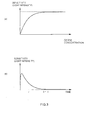
- Fig. 3 is a graph showing a relationship between light intensity and ozone concentration and a relationship between light intensity and time in accordance with this embodiment.
- Fig. 4 is a functional block diagram of the information processing unit in accordance with this embodiment.
- An
exhaust gas analyzer 100 in accordance with one embodiment of the present claimed invention will be described in detail with reference to the accompanying drawings. - The exhaust
gas measuring system 100 in accordance with this embodiment is to measure concentration of various components in exhaust gas as being sample gas while a vehicle is actually in motion with the exhaustgas measuring system 100 loaded on a trunk of the vehicle and, as shown in Fig. 1, comprises threedifferent analyzers analyzers information processing unit 7 that receives actually measured data from eachanalyzer - Each component will be described.
- First, an
infrared gas analyzer 4 to measure each concentration of CO, CO2, H2O, a hydrogenflame ionization detector 5 to measure concentration of THC (total hydrocarbon), and a chemiluminescent nitrogen oxide analyzer 6 (hereinafter also called as a CLD type NOx analyzer 6) to measure concentration of NOx are used as theanalyzers - The
infrared gas analyzer 4 is of a nondispersive type and is so arranged to measure light intensity of each wavelength by a photo detector at a time when infrared rays of characteristic wavelength which each CO, CO2, H2O absorbs passes through the sample gas (the exhaust gas), to output each of them and to compare each of the output values with a reference value at a time when no light is absorbed so that light absorbency of each wavelength can be calculated. The light absorbency of each wavelength shows the concentration of each component of CO, CO2, and H2O. - The hydrogen
flame ionization detector 5 is of a type wherein fuel gas is mixed into the sample gas (the exhaust gas) at a constant ratio, the mixed gas is burned in a combustion chamber (a chimney) to which an electric field is applied, electric current generated due to ionization of THC contained in the sample gas is captured, and the electric current is amplified and output. Then the hydrogenflame ionization detector 5 can calculate an amount (concentration) of THC from the output value of the electric current. In addition to the fuel gas, combustion supporting gas (air) also is introduced into the hydrogenflame ionization detector 5. - The CLD type NOx analyzer 6 can measure an amount (concentration) of NOx contained in the exhaust gas and comprises an
NO converter 61, anozone generator 62, areactor 63, and a photo detector (not shown in drawings). TheNO converter 61 is to convert NOx into NO and is arranged at one 6a of a pair ofparallel paths electromagnetic switch valve 65 is arranged at a terminal end of theparallel paths reactor 63 only through either one of theparallel paths ozone generator 62 imports atmospheric air without dehumidification, converts oxygen contained in the atmospheric air into ozone and outputs it as ozone-containing gas. Thereactor 63 is a box body having a certain volume and comprises a samplegas introducing port 63a, an ozone-containinggas introducing port 63b and a leading-outport 63c. The gas from either one of theparallel paths switch valve 65 as mentioned above is introduced into the samplegas introducing port 63a and the ozone-containing gas from theozone generator 62 is introduced into the ozone-containinggas introducing port 63b. Each gas is mixed inside thereactor 63, which causes a chemiluminescent response. The photo detector is to measure the light intensity due to a response in thereactor 63 and, for example, a photoelectron multiplier is used as the photo detector in this embodiment. - The flow path system comprises a
main flow path 1 that plays a role as a bypath to pass almost all of the exhaust gas, and multiple (two)sub-flow paths main flow path 1. Theinfrared gas analyzer 4 is arranged on themain flow path 1, the hydrogenflame ionization detector 5 is arranged on one of the sub-flow paths 2 (a first sub-flow path 2) and the CLD type NOx analyzer 6 is arranged on other sub-flow path 3 (a second sub-flow path 3) respectively. - An upstream end of the
main flow path 1 opens as amain port 11 and asuction pump 19 is arranged at the most downstream side of themain flow path 1. An exhaust duct of a vehicle is connected to themain port 11 and an amount of the exhaust gas required for measurement is introduced into themain flow path 1 by sucking the exhaust gas by the use of thesuction pump 19. - More concretely, in succession to the main port 11 a
drain separator 13 to remove liquid moisture contained in the exhaust gas, afilter 14, a flow rate control pipe (capillary) 15a, abifurcated part 16, theinfrared gas analyzer 4, a flow rate control pipe (capillary) 15b, aninterflow part 18, thesuction pump 19 are arranged serially in this order. Since portions from the exhaust duct of the vehicle to thedrain separator 13 are connected with an unheated piping alone at least without using a heated piping, the exhaust gas is introduced into eachanalyzer pressure control valve 17a connected downstream of theinfrared gas analyzer 4 is to control pressure in the flow path system between thecapillaries infrared gas analyzer 4 constant in cooperation with each capillary 15, 15b. - The
sub-flow paths main flow path 1 at thebifurcated part 16 and to be connected to themain flow path 1 again at theinterflow part 18. - A flow rate control pipe (capillary) 21 and the hydrogen
flame ionization detector 5 are arranged in this order on the firstsub-flow path 2. The flowrate control pipe 21 is to limit an amount of gas that flows into the firstsub-flow path 2 to a flow rate (very small amount compared with the flow rate of the exhaust gas that flows into the main flow path 1) necessary for measuring concentration of THC. - A flow rate control pipe (capillary) 31 and the CLD type NOx
analyzer 6 are arranged in this order from upstream on the secondsub-flow path 3. The flow rate control pipe (capillary) 31 is to limit an amount of gas that flows into the secondsub-flow path 3 to a flow rate (very small amount compared with the flow rate of the exhaust gas that flows into the main flow path 1) necessary for measuring concentration of NOx. - The
pressure control valve 17b connected to theinterflow part 18 is to control pressure of eachsub-flow path flame ionization detector 5 and the CLD type NOxanalyzer 6 constant in cooperation with each capillary 21, 22 arranged upstream of eachsub-flow path - The
information processing unit 7 is, as shown in Fig. 2, of multi-purpose or exclusive use comprising aCPU 701, amemory 702, an input/output channel 703, aninput device 704 such as a keyboard, and adisplay 705. An analog-digital converting circuit such as an A/D converter, a D/A converter, and an amplifier (not shown in drawings) arranged at a side of the analyzers is connected to the input/output channel 703. Theinformation processing unit 7 at least fulfills function as a controlling part that controls the valve arranged on the flow path system to open or close or temperature of a heater, and an analyzing part that receives detected data output from eachanalyzer CPU 701 and its peripheral equipment according to a program stored in a predetermined area of thememory 72. Theinformation processing unit 7 is not necessarily integrated physically, and may be separated into multiple instruments connected by a fixed line or wireless. - In this embodiment, as mentioned above, since the CLD type NOx
analyzer 6 is so arranged that atmospheric air is introduced into theozone generator 62 without dehumidification, a dehumidifier and a drier that are necessary for a conventional analyzer can be omitted. This arrangement makes it possible to reduce electrical consumption to a large extent and to downsize the analyzer, resulting in facilitating this analyzer being loaded on a vehicle. - As mentioned above if the atmospheric air is directly introduced into the
ozone generator 62, the ozone concentration in the ozone-containing gas output from theozone generator 62 fluctuates due to fluctuation of oxygen concentration when humidity in the atmospheric air fluctuates. As a result, a measurement error of the nitrogen oxide might be generated. - Then, in this embodiment, a relationship between the cubic volume of the
reactor 63, the pressure in thereactor 63, the flow rate of introducing the sample gas into thereactor 63 and the flow rate of introducing the ozone-containing gas into thereactor 63 is so set that the response of light emission is completed in thereactor 63, even though the ozone concentration fluctuates within an expected range, so that the fluctuation of the ozone concentration does not have an impact on the measurement value or the impact can be reduced as much as possible. - More concretely, for better understanding, a relationship between the light intensity, the concentration of NO or ozone, or the time period of light emission will be explained prior to explaining the method.
- When nitric oxide reacts with ozone, nitrogen peroxide (NO2) is generated and a part of the generated nitrogen peroxide becomes excitation NO2 at a certain ratio. When excitation NO2* returns to a base state, the excitation energy is released as the light energy as shown in equation (2). A process of the light emission is expressed by the following chemical equation.


- Where each of k2, k3, k4 is a constant that defines the velocity of each response.
- The velocity of decreasing NO during a process of equation (1) through equation (3) is expressed by the following equation (4).
-d [NO] /dt=k2 [NO] [O3] (4)
- Where [ ] expresses the concentration.
- Since a generating amount of NO2*, namely the concentration of NO2* is an amount that a current amount of the NO concentration is subtracted from an initial value of the NO concentration, the generating amount of NO2* is expressed by the following equation (5).
[NO] (O)- [NO] = [NO2*] (5)
- Where, [NO] (0) is an initial value of the NO concentration.
- The response of the light emission expressed by the equation (2) is generated at a certain ratio (there might be a case that a response of the light emission is not generated at a certain ratio due to a quenching phenomenon expressed by the equation (3)) every time NO2* is generated due to the chemical response expressed by the equation (1), and since the light intensity I is an integral value of a single shot of the light emission due to the response, the light intensity I is proportional to an amount of generated NO2*, namely the concentration of NO2. The light intensity I is expressed by the following equation (6).
I=A1 · [NO2] (6)
- Where A1 is a proportionality constant.
- Then the light intensity I is obtained from a relationship between the time t and the concentration of O3 by the following equation (7).
I=A · {1-exp(-k2 · [O3] · t)} (7)
- Where A=A1 · [NO] (0)
- As is clear from the equation (7), a time constant t of the light emission system is expressed by the following equation (8).
τ =1/(k2 · [O3]) (8)
- As a result, k2 can be considered to be a characteristic value that is intrinsic to the light emission system that specifies the time constant.
- Then in this embodiment, a steady state (each of the concentration, the flow rate and the pressure of the gas is kept constant) is produced, t is kept at a certain value Tc (the gas average residence time in the
reactor 63 is kept constant), then only the concentration of O3 is varied in the steady state and finally k2 is obtained based on the change of the light intensity I at that time. - Conversely, in this embodiment, the light emission is completed in the
reactor 63 even though the ozone concentration fluctuates in some degree and the concentration of NO can be obtained uniquely from the light intensity by setting a parameter that specifies the gas average residence time t in thereactor 63, namely a relationship between the cubic volume of thereactor 63, the pressure in thereactor 63, the flow rate of introducing the sample gas into thereactor 63, the flow rate of introducing the ozone-containing gas into thereactor 63. - A method will be described as follows.
- First, the reference sample gas containing nitrogen oxide (in this embodiment, NO) with constant concentration and the reference ozone-containing gas with known concentration pass at a certain amount in stead of the exhaust gas and the ozone-containing gas, and the pressure in the
reactor 63 is kept constant (a step to produce the steady state). - In this steady state, the average period Tc while the mixed gas resides in the
reactor 63 is a constant value obtained by the following equation (10).
Tc=Vc×Pc/Qc (10)
- Where Vc is the cubic volume of the
reactor 63, Pc is the pressure in thereactor 63 in the steady state and Qc is the total amount of the gas flowing into thereactor 63 in the steady state. - A relationship between the light intensity (sensitivity) I in the steady state and the ozone concentration [O3] is expressed by the following equation (11) obtained from the equations (7) and (10). A graph wherein the horizontal axis is the ozone concentration [O3], and the vertical axis is the light intensity (sensitivity) I is shown in Fig. 3(a).
I=A(1-exp(-k2 · Tc · [O3]) (11)
- Where A=A1 · [NO] (0)
- Next, the ozone concentration alone is changed and a changed value of the light intensity corresponding to it is detected, and then response characteristics of the ozone concentration-light emission that shows a relationship between the ozone concentration and the light intensity, namely the chemiluminescent response is obtained. More concretely, a point where a change amount of the light intensity corresponding to a rising amount of the ozone concentration becomes less than or equal to a predetermined minute amount, namely a point where a change of sensitivity becomes almost nothing is obtained by raising the ozone concentration gradually so as to increase the response speed of NO+O3 (a step to obtain the response characteristics).
- More concretely, if the point is set as a point of about 95% of a saturation value of the light intensity and the point is conceived to be a point where the time when the response of NO+O3 completes generally equals to the time when the sample gas passes, a following equation (12) can be derived.
3·τ=Tc (12)
- If the equation (8) and the equation (10) are substituted to the equation (12), the equation (13) is derived and the characteristic value k2 can be obtained.
k2=3/ ([O3] c×Vc×Pc/Qc) (13)
- Where [O3] c is a value of the ozone concentration at a time when the change of the light intensity becomes equal to or less than the predetermined minute amount. In addition, τ is tripled in the equation (12), however, it is an example of a case where the point is set as the point of about 95% of the saturation value, and it is not limited to this.
- In addition, the ozone concentration only is changed and each value of the light intensity corresponding to multiple values of the ozone concentration is detected, and then the equation (11) as being the response characteristics is specified so that each value of the light intensity falls on each point, for example, by the use of the least-square method (the step to obtain the response characteristics). K2 as being a characteristic value of this measuring system may be obtained by the specified equation (11).
- Finally, the relationship of the cubic volume V of the
reactor 63, the pressure P of thereactor 63, the flow rate Q of introducing the sample gas and the ozone-containing gas into thereactor 63 is set so that the response of the light emission is generated only in thereactor 63 even though the ozone concentration of the ozone-containing gas varies within the predetermined range based on thus obtained characteristic value k2 (a step to set the parameter). - More concrete explanation is as follows.
- As is clear from the equation (7), the saturation value of the light intensity (sensitivity) I is A=A1 · [NO] (0), and the value to be obtained as the sensitivity is the concentration of NO, namely [NO] (0). As a result, the bigger a value of t, the less an effect on the light intensity (sensitivity) I due to fluctuation of the value of t.
- Then in this embodiment, in order not to lose measurement accuracy in spite of fluctuation of the ozone concentration, the average period while the mixed gas resides in the reactor 63 tQ=V×P/Q is defined based on the time constant τ (=1/(k2 · [O3])) so that the measurement accuracy is within almost an unsusceptible range even though the time constant τ changes because the ozone concentration fluctuates a little from the reference value, since the time constant τ of this graph can be expressed as 1/(k2 · [O3]) from the equation (8). As mentioned in the equation (14), tQ is defined to be equal to or more than n times of τ (more concretely, triple of 95% of the saturation value).
3 · τ≦tQ=V×P/Q (14)
- Fig. 3(b) shows a time change of the light intensity when a predetermined amount of NO is introduced into the
reactor 63 in an impulse form. As is clear from Fig. 3(b), that the average period tQ is set more than or equal to triple of τ shows that almost all (more than or equal to 95%) of one cycle of the light emission is brought to completion within the period tQ. - It is a matter of course that the average period tQ has to be set more than or equal to triple of τ when a fluctuation range of the ozone concentration is big. Conversely, it may be less than triple of τ when a fluctuation range of the ozone concentration is not big. To be brief, the average period tQ may be estimated to be more than or equal to n times of τ in compliance with the fluctuation range of the ozone concentration. The ozone concentration [O3] at a time of defining τ may be set to be, for example, a center value of the fluctuation range.
- Since the cubic volume V of the
reactor 63 can not be changed after the CLD type NOx analyzer is completed, the pressure P or the flow rate Q is set by adjusting the pressure control valve or the capillary so as to meet the average period tQ obtained by the equation (14) and the relationship of the cubic volume V of thereactor 63, the pressure P in thereactor 63, and the flow rate Q of introducing the gas into thereactor 63 are set. In addition, also the cubic volume V of thereactor 63 may be adjusted at a stage of designing or developing the analyzer. - As mentioned above, in accordance with this embodiment, no matter how complicated the system is, it is not very difficult to produce the steady state. As a result of this, the characteristic value k2 can be obtained easily from the change of the ozone concentration and the change of the light intensity in the steady state.
- It is possible to set the relationship of the cubic volume V, the pressure P and the flow rate Q easily so that the luminescence response is brought to completion in the
reactor 63 without fail as long as the change rate can be estimated by the use of the characteristic value k2 even though the ozone concentration of the ozone-containing gas changes, thereby making it possible to measure the concentration of NO with accuracy by lessening the measurement error. - In addition, since the concentration of NO can be measured with accuracy even though the concentration of ozone is unstable, it is possible to introduce the atmospheric air without dehumidification directly into the
ozone generator 62. As a result, power-saving or downsizing due to omission of the dehumidifier or the drier makes it possible to provide a real time nitrogen oxide analyzer especially very preferable for a vehicle-mountable use. - The present claimed invention is not limited to the above-mentioned embodiment.
- For example, the
information processing unit 7 may automatically obtain the response characteristics or calculate the parameter. - More concretely, a predetermined installation program is installed on the
information processing unit 7 and theinformation processing unit 7 serves as the following functions in cooperation with aCPU 701, amemory 702, and peripheral devices based on the installation program. - More specifically, as shown in Fig. 4, the
information processing unit 7 functions as a responsecharacteristics obtaining part 71 that obtains ozone concentration-luminescence response characteristics as being the relationship between the ozone concentration and the light intensity by the chemiluminescent response obtained by varying the ozone concentration alone in the steady state and that memorizes it in the response characteristics storing part D1, and as aparameter calculating part 72 that calculates a relationship of the parameter (the cubic volume of thereactor 63, the pressure of thereactor 63, the flow rate of the sample gas introducing into thereactor 63, the flow rate of the ozone-containing gas introducing into the reactor 63) that determines an average resident time of the sample gas in thereactor 63 so that the luminescence response is generated only in thereactor 63 even though the ozone concentration of the sample gas changes within a predetermined range based on the ozone concentration-luminescence response characteristics. - As is the case with the step to set the parameter, the
parameter calculating part 72 calculates the characteristic value k2 based on the ozone concentration-luminescence response characteristics memorized in the response characteristics storing part D1, and calculates the relationship of the parameter based on the characteristic value K2. - Furthermore, a parameter
automatic setting part 73 may be arranged on theinformation processing unit 7. The capillary and the pressure control valve can be controlled by theinformation processing unit 7, a pressure sensor or a flow rate sensor that measures the pressure P in thereactor 63, the flow rate Q of the sample gas and the ozone-containing gas introduced into thereactor 63 is arranged, the measured information is transmitted to theinformation processing unit 7, and the capillary or the pressure control valve is controlled based on the calculated result of theparameter calculating part 72. - The other arrangement of the component is not limited to the embodiment described in drawings and there may be various modifications without departing from the spirit of the invention.
Claims (12)
- A method of measuring the concentration of nitrogen oxide in an nitrogen oxide analyzer (6) comprising;a reactor (63) where ozone-containing gas and sample gas continuously introduced in a time-series order are mixed and the mixed gas is passed out through an output port,a photo detector that detects light intensity of chemiluminescence caused by mixing the ozone-containing gas and the sample gas in the reactor (63), andan information processing unit (7) that calculates concentration of nitrogen oxide in the sample gas based on the light intensity detected by the light detector, whereinthe information processing unit (7) comprises;a response characteristics obtaining part that obtains ozone concentration-luminescence response characteristics, which is determined by a relationship between the ozone concentration and the light intensity, by the chemiluminescent response obtained by varying the ozone concentration alone in a steady state wherein reference sample gas containing nitrogen oxide with constant concentration and reference ozone gas with known ozone concentration pass at a constant flow rate and wherein the pressure in the reactor (63) is kept constant.
- The method of claim 1, wherein
a parameter calculating part calculates a relationship of parameters that determines an average resident time of the sample gas in the reactor (63) based on the ozone concentration-luminescence response characteristics. - The method of claim 1 or 2, wherein
the parameters include at least cubic volume of the reactor (63), pressure in the reactor (63), a flow rate of introducing the sample gas into the reactor (63) and a flow rate of introducing the ozone-containing gas into the reactor (63). - The method of claim 2 or 3, wherein
the parameter calculating part calculates a characteristic value that specifies a chemiluminescent response time constant that is intrinsic to the nitrogen oxide analyzer (6) based on the ozone concentration-luminescence response characteristics, and calculates the relationship of the parameters based on the characteristic value. - The method of claim 4, wherein
the response characteristics obtaining part specifies a time when the change amount of the light intensity relative to a predetermined change amount of the ozone concentration becomes less than or equal to a predetermined minute amount as the ozone concentration-luminescence response characteristics, and
the parameter calculating part calculates the characteristic value from the cubic volume of the reactor (63), the pressure in the reactor (63) and the flow rate of introducing the sample gas and the ozone-containing gas into the reactor (63). - The method of any of claims 1 through 5, wherein
the response characteristics obtaining part detects each value of the light intensity corresponding to multiple values of the ozone concentration, and obtains the ozone concentration-luminescence response characteristics as being a relational equation between the ozone concentration and the light intensity that almost satisfies each detected value of the light intensity. - The method of any of claims 1 through 6 wherein
light intensity of chemiluminescence caused by mixing the ozone-containing gas and the sample gas in the reactor (63) is detected so as to calculate the nitrogen oxide concentration in the sample gas based on the light intensity, and wherein
a step to produce a steady state is included that reference sample gas containing nitrogen oxide with constant concentration and reference ozone gas with known concentration flow at a certain flow rate and that the pressure in the reactor (63) is kept constant so as to produce a steady state,
a step to obtain a response characteristics that changes the ozone concentration alone in the steady state and that obtains ozone concentration-luminescence response characteristics showing a relationship between the ozone concentration and the light intensity by the chemiluminescent response obtained by varying the ozone concentration alone, and
a step to set parameters that sets a relationship of parameters that determines an average resident time of the sample gas in the reactor (63) so that the luminescence response is generated almost only in the reactor (63) even though the ozone concentration of the ozone-containing gas changes within a predetermined range based on the ozone concentration-luminescence response characteristics. - The method of claim 7, wherein
the parameter includes at least the cubic volume of the reactor (63), the pressure in the reactor (63), the flow rate of the sample gas introducing into the reactor (63) and the flow rate of the ozone-containing gas introducing into the reactor (63). - The method of claim 7, wherein
a characteristic value that specifies a chemiluminescent response time constant intrinsic to the nitrogen oxide analyzer (6) is calculated based on the ozone concentration-luminescence response characteristics and the relationship of the parameter is set based on the characteristic value so that the luminescence response is generated almost in the reactor (63) alone even though the ozone concentration of the sample gas changes within a predetermined range in the step to set the parameter. - The method of claim 9, wherein
the characteristic value is calculated from the concentration of ozone, the cubic volume of the reactor (63), the pressure in the reactor (63), and the flow rate of the gas introducing into the reactor (63) at a time when a change amount of the light intensity corresponding to a predetermined change amount of the concentration of ozone becomes less than or equal to a predetermined minute amount in the step to set the parameter. - A nitrogen oxide analyzer (6) comprising;
a reactor (63) where ozone-containing gas and exhaust gas continuously introduced in a time-series order are mixed and the mixed gas is passed out through an output port,
a photo detector that detects intensity of light generated in the reactor (63) by mixing the ozone-containing gas and the exhaust gas,
an information processing unit (7) that calculates the nitrogen oxide concentration in the exhaust gas based on the light intensity detected by the photo detector, and
an ozone generator (62) that introduces atmospheric air without dehumidification and that generates the ozone-containing gas by converting oxygen in the atmospheric air into ozone. - The nitrogen oxide analyzer (6) of claim 11, wherein
the nitrogen oxide analyzer (6) is a vehicle-mountable analyzer.
Applications Claiming Priority (1)
| Application Number | Priority Date | Filing Date | Title |
|---|---|---|---|
| JP2005107865A JP4804782B2 (en) | 2005-04-04 | 2005-04-04 | Nitrogen oxide analyzer and parameter setting method applied to nitrogen oxide analyzer |
Publications (3)
| Publication Number | Publication Date |
|---|---|
| EP1710563A2 true EP1710563A2 (en) | 2006-10-11 |
| EP1710563A3 EP1710563A3 (en) | 2008-06-04 |
| EP1710563B1 EP1710563B1 (en) | 2011-02-16 |
Family
ID=36603423
Family Applications (1)
| Application Number | Title | Priority Date | Filing Date |
|---|---|---|---|
| EP06007059A Expired - Lifetime EP1710563B1 (en) | 2005-04-04 | 2006-04-03 | Method of measuring the concentration of nitrogen oxide and nitrogen oxide analyzer |
Country Status (4)
| Country | Link |
|---|---|
| US (1) | US8440466B2 (en) |
| EP (1) | EP1710563B1 (en) |
| JP (1) | JP4804782B2 (en) |
| DE (1) | DE602006020086D1 (en) |
Families Citing this family (10)
| Publication number | Priority date | Publication date | Assignee | Title |
|---|---|---|---|---|
| EP2324349B1 (en) * | 2008-09-03 | 2016-11-30 | Testo AG | Method and apparatus for capturing measurement values and displaying measurement values |
| DE112011105925B4 (en) * | 2011-12-06 | 2023-02-09 | Tahoe Research, Ltd. | Microelectronic transistor and method of making the same |
| RU2493556C1 (en) * | 2012-02-10 | 2013-09-20 | Владимир Петрович Челибанов | Method and apparatus for determining concentration of nitrogen oxide(no) in gaz medium |
| JP5767158B2 (en) * | 2012-04-26 | 2015-08-19 | 日本特殊陶業株式会社 | Gas sensor evaluation method and gas sensor evaluation apparatus |
| JP7001579B2 (en) | 2018-12-27 | 2022-02-04 | 株式会社堀場製作所 | Gas analyzer, gas analysis program, and gas analysis method |
| CN111308025A (en) * | 2020-04-20 | 2020-06-19 | 淄博青禾检测科技有限公司 | Wide-range nitric oxide sensor system |
| CN113702285A (en) * | 2021-07-21 | 2021-11-26 | 北京师范大学 | Ozone sailing monitor |
| CN114136898B (en) * | 2021-11-05 | 2023-03-31 | 中国科学院合肥物质科学研究院 | System and method for measuring net generation rate of high-precision cavity ozone photochemistry |
| CN114018848B (en) * | 2021-11-16 | 2022-11-11 | 无锡时和安全设备有限公司 | Visual nitrogen oxide conversion system |
| CN120064565B (en) * | 2025-01-21 | 2025-11-18 | 中国科学院合肥物质科学研究院 | Atmospheric nitrogen trioxide transmission efficiency calibration and reactivity measurement system and method |
Citations (1)
| Publication number | Priority date | Publication date | Assignee | Title |
|---|---|---|---|---|
| US3882028A (en) | 1974-05-17 | 1975-05-06 | Thermo Electron Corp | Multiple chamber chemiluminescent analyzer |
Family Cites Families (17)
| Publication number | Priority date | Publication date | Assignee | Title |
|---|---|---|---|---|
| JPS61151446A (en) * | 1984-12-26 | 1986-07-10 | Shimadzu Corp | Chemiluminescent gas analyzer |
| US4822564A (en) * | 1985-07-02 | 1989-04-18 | Sensors, Inc. | Chemiluminescent gas analyzer for measuring the oxides of nitrogen |
| CH670706A5 (en) * | 1986-06-20 | 1989-06-30 | Tecan Ag | |
| JP2605718B2 (en) * | 1987-06-22 | 1997-04-30 | 株式会社島津製作所 | Chemiluminescent nitrogen oxide measuring device |
| JPH07111399B2 (en) * | 1991-02-19 | 1995-11-29 | 株式会社島津製作所 | Chemiluminescence type nitrogen oxide measuring device |
| JPH06167450A (en) * | 1992-11-30 | 1994-06-14 | Shimadzu Corp | Chemiluminescence analyzer |
| JPH07301603A (en) * | 1994-04-30 | 1995-11-14 | Shimadzu Corp | Chemiluminescence type nitrogen oxide measuring device |
| JP2000035402A (en) * | 1998-07-16 | 2000-02-02 | Shimadzu Corp | Chemiluminescent nitrogen oxide meter |
| US6207460B1 (en) * | 1999-01-14 | 2001-03-27 | Extraction Systems, Inc. | Detection of base contaminants in gas samples |
| JP4253962B2 (en) * | 1999-11-30 | 2009-04-15 | 株式会社島津製作所 | Gas dehumidifier |
| JP2002005838A (en) * | 2000-06-23 | 2002-01-09 | Shimadzu Corp | Chemiluminescence analyzer |
| EP1243917A1 (en) * | 2001-03-23 | 2002-09-25 | Instrumentarium Corporation | Nitric oxide analyzer |
| EP1243918A3 (en) * | 2001-03-23 | 2004-10-06 | Instrumentarium Corporation | An improved chemiluminescent gas analyzer |
| KR100407447B1 (en) * | 2001-07-04 | 2003-11-28 | 율촌화학 주식회사 | Apparatus for generating ozone in high concentration |
| JP2004045297A (en) * | 2002-07-15 | 2004-02-12 | Horiba Ltd | Measuring apparatus |
| JP4264239B2 (en) * | 2002-08-28 | 2009-05-13 | 株式会社貝印刃物開発センター | Case for firewood |
| US20050199484A1 (en) * | 2004-02-10 | 2005-09-15 | Franek Olstowski | Ozone generator with dual dielectric barrier discharge and methods for using same |
-
2005
- 2005-04-04 JP JP2005107865A patent/JP4804782B2/en not_active Expired - Fee Related
-
2006
- 2006-04-03 DE DE602006020086T patent/DE602006020086D1/en not_active Expired - Lifetime
- 2006-04-03 EP EP06007059A patent/EP1710563B1/en not_active Expired - Lifetime
- 2006-04-04 US US11/278,609 patent/US8440466B2/en not_active Expired - Fee Related
Patent Citations (1)
| Publication number | Priority date | Publication date | Assignee | Title |
|---|---|---|---|---|
| US3882028A (en) | 1974-05-17 | 1975-05-06 | Thermo Electron Corp | Multiple chamber chemiluminescent analyzer |
Non-Patent Citations (2)
| Title |
|---|
| RIDLEY, B. A., REVIEW OF SCIENTIFIC INSTRUMENTS, vol. 45, 1974, pages 742 - 746 |
| STEFFENSON, D. M. ET AL., ANALYTICAL CHEMISTRY, vol. 46, 1974, pages 1704 - 1708 |
Also Published As
| Publication number | Publication date |
|---|---|
| JP4804782B2 (en) | 2011-11-02 |
| US20060223190A1 (en) | 2006-10-05 |
| DE602006020086D1 (en) | 2011-03-31 |
| EP1710563A3 (en) | 2008-06-04 |
| EP1710563B1 (en) | 2011-02-16 |
| JP2006284500A (en) | 2006-10-19 |
| US8440466B2 (en) | 2013-05-14 |
Similar Documents
| Publication | Publication Date | Title |
|---|---|---|
| US7454950B2 (en) | Vehicle exhaust gas analyzer | |
| Zahn et al. | A fast and precise chemiluminescence ozone detector for eddy flux and airborne application | |
| US10876929B2 (en) | Exhaust gas analysis device, exhaust gas analysis method and storage medium recording programs for exhaust gas analysis device | |
| US8440466B2 (en) | Nitrogen oxide analyzer and method for setting parameter applied to nitrogen oxide analyzer | |
| CN101915743B (en) | Method for calibrating online ozone analyzer | |
| CN102183468A (en) | Interference correction and concentration inversion method of multi-component gas analysis | |
| JPWO2018105169A1 (en) | Gas analyzer and gas analysis method | |
| JP5192350B2 (en) | Sensor evaluation system | |
| Ulanovsky et al. | The FOZAN-II fast-response chemiluminescent airborne ozone analyzer | |
| US7328606B2 (en) | Exhaust gas measuring device and method for measuring exhaust gas | |
| Xu et al. | Design of nitrogen oxide detection system based on non-dispersive infrared technology | |
| Gluck et al. | Evaluation of NOx flue gas analyzers for accuracy and their applicability for low-concentration measurements | |
| JP3998190B2 (en) | Method and apparatus for analyzing nitrogen compounds in particulate matter contained in exhaust gas from combustion means | |
| CN120102797A (en) | Ozone generation rate monitoring system and monitoring method | |
| EP1710569A1 (en) | Gas analyzer and method for controlling hydrogen flame ionization detector | |
| Manap et al. | Ammonia sensing and a cross sensitivity evaluation with atmosphere gases using optical fiber sensor | |
| US20050189239A1 (en) | Advanced dual sensor technology for a continuous emission monitoring system | |
| Xu et al. | Temperature-corrected spectroscopic evaluation method for gas concentration monitoring | |
| Cobourn et al. | Airborne in-situ measurement of particulate sulfur and sulfuric acid with flame photometry and thermal analysis | |
| JP2006284508A (en) | On-vehicle exhaust gas analyzer | |
| JPH09145644A (en) | Analyzer with detection element that requires temperature control | |
| CN114624383A (en) | Wide-range smoke dust and smoke gas analysis instrument and analysis method based on low-concentration sensor | |
| CN214252188U (en) | Wide-range smoke dust and flue gas analysis instrument based on low-concentration sensor | |
| CN120445897A (en) | A carbon dioxide absorbent performance evaluation system | |
| JP6213191B2 (en) | Gas analyzer |
Legal Events
| Date | Code | Title | Description |
|---|---|---|---|
| PUAI | Public reference made under article 153(3) epc to a published international application that has entered the european phase |
Free format text: ORIGINAL CODE: 0009012 |
|
| AK | Designated contracting states |
Kind code of ref document: A2 Designated state(s): AT BE BG CH CY CZ DE DK EE ES FI FR GB GR HU IE IS IT LI LT LU LV MC NL PL PT RO SE SI SK TR |
|
| AX | Request for extension of the european patent |
Extension state: AL BA HR MK YU |
|
| PUAL | Search report despatched |
Free format text: ORIGINAL CODE: 0009013 |
|
| AK | Designated contracting states |
Kind code of ref document: A3 Designated state(s): AT BE BG CH CY CZ DE DK EE ES FI FR GB GR HU IE IS IT LI LT LU LV MC NL PL PT RO SE SI SK TR |
|
| AX | Request for extension of the european patent |
Extension state: AL BA HR MK YU |
|
| 17P | Request for examination filed |
Effective date: 20081001 |
|
| 17Q | First examination report despatched |
Effective date: 20081106 |
|
| AKX | Designation fees paid |
Designated state(s): DE IT NL SE |
|
| GRAP | Despatch of communication of intention to grant a patent |
Free format text: ORIGINAL CODE: EPIDOSNIGR1 |
|
| GRAS | Grant fee paid |
Free format text: ORIGINAL CODE: EPIDOSNIGR3 |
|
| GRAA | (expected) grant |
Free format text: ORIGINAL CODE: 0009210 |
|
| AK | Designated contracting states |
Kind code of ref document: B1 Designated state(s): DE IT NL SE |
|
| REF | Corresponds to: |
Ref document number: 602006020086 Country of ref document: DE Date of ref document: 20110331 Kind code of ref document: P |
|
| REG | Reference to a national code |
Ref country code: DE Ref legal event code: R096 Ref document number: 602006020086 Country of ref document: DE Effective date: 20110331 |
|
| REG | Reference to a national code |
Ref country code: NL Ref legal event code: T3 |
|
| REG | Reference to a national code |
Ref country code: SE Ref legal event code: TRGR |
|
| PLBE | No opposition filed within time limit |
Free format text: ORIGINAL CODE: 0009261 |
|
| STAA | Information on the status of an ep patent application or granted ep patent |
Free format text: STATUS: NO OPPOSITION FILED WITHIN TIME LIMIT |
|
| 26N | No opposition filed |
Effective date: 20111117 |
|
| REG | Reference to a national code |
Ref country code: DE Ref legal event code: R097 Ref document number: 602006020086 Country of ref document: DE Effective date: 20111117 |
|
| PGFP | Annual fee paid to national office [announced via postgrant information from national office to epo] |
Ref country code: NL Payment date: 20180314 Year of fee payment: 13 |
|
| PGFP | Annual fee paid to national office [announced via postgrant information from national office to epo] |
Ref country code: DE Payment date: 20180320 Year of fee payment: 13 |
|
| PGFP | Annual fee paid to national office [announced via postgrant information from national office to epo] |
Ref country code: IT Payment date: 20180420 Year of fee payment: 13 |
|
| PGFP | Annual fee paid to national office [announced via postgrant information from national office to epo] |
Ref country code: SE Payment date: 20180411 Year of fee payment: 13 |
|
| REG | Reference to a national code |
Ref country code: DE Ref legal event code: R119 Ref document number: 602006020086 Country of ref document: DE |
|
| REG | Reference to a national code |
Ref country code: SE Ref legal event code: EUG |
|
| REG | Reference to a national code |
Ref country code: NL Ref legal event code: MM Effective date: 20190501 |
|
| PG25 | Lapsed in a contracting state [announced via postgrant information from national office to epo] |
Ref country code: SE Free format text: LAPSE BECAUSE OF NON-PAYMENT OF DUE FEES Effective date: 20190404 Ref country code: NL Free format text: LAPSE BECAUSE OF NON-PAYMENT OF DUE FEES Effective date: 20190501 Ref country code: DE Free format text: LAPSE BECAUSE OF NON-PAYMENT OF DUE FEES Effective date: 20191101 |
|
| PG25 | Lapsed in a contracting state [announced via postgrant information from national office to epo] |
Ref country code: IT Free format text: LAPSE BECAUSE OF NON-PAYMENT OF DUE FEES Effective date: 20190403 |