EP1710459A1 - Fixed-type constant velocity universal joint - Google Patents
Fixed-type constant velocity universal joint Download PDFInfo
- Publication number
- EP1710459A1 EP1710459A1 EP04807034A EP04807034A EP1710459A1 EP 1710459 A1 EP1710459 A1 EP 1710459A1 EP 04807034 A EP04807034 A EP 04807034A EP 04807034 A EP04807034 A EP 04807034A EP 1710459 A1 EP1710459 A1 EP 1710459A1
- Authority
- EP
- European Patent Office
- Prior art keywords
- constant velocity
- universal joint
- velocity universal
- type constant
- fixed type
- Prior art date
- Legal status (The legal status is an assumption and is not a legal conclusion. Google has not performed a legal analysis and makes no representation as to the accuracy of the status listed.)
- Withdrawn
Links
- 239000013013 elastic material Substances 0.000 claims abstract description 14
- 230000005540 biological transmission Effects 0.000 claims description 6
- 239000004033 plastic Substances 0.000 claims description 6
- 230000000694 effects Effects 0.000 claims description 3
- 239000000463 material Substances 0.000 claims description 3
- 230000000717 retained effect Effects 0.000 abstract 1
- 238000003825 pressing Methods 0.000 description 6
- 230000004048 modification Effects 0.000 description 4
- 238000012986 modification Methods 0.000 description 4
- 230000008878 coupling Effects 0.000 description 3
- 238000010168 coupling process Methods 0.000 description 3
- 238000005859 coupling reaction Methods 0.000 description 3
- 238000006073 displacement reaction Methods 0.000 description 3
- 239000011347 resin Substances 0.000 description 2
- 229920005989 resin Polymers 0.000 description 2
- 230000015572 biosynthetic process Effects 0.000 description 1
- 238000010276 construction Methods 0.000 description 1
- 238000005520 cutting process Methods 0.000 description 1
- 238000010586 diagram Methods 0.000 description 1
- 238000004519 manufacturing process Methods 0.000 description 1
- 238000000034 method Methods 0.000 description 1
- 238000003466 welding Methods 0.000 description 1
Images




Classifications
-
- B—PERFORMING OPERATIONS; TRANSPORTING
- B62—LAND VEHICLES FOR TRAVELLING OTHERWISE THAN ON RAILS
- B62D—MOTOR VEHICLES; TRAILERS
- B62D7/00—Steering linkage; Stub axles or their mountings
- B62D7/22—Arrangements for reducing or eliminating reaction, e.g. vibration, from parts, e.g. wheels, of the steering system
- B62D7/224—Arrangements for reducing or eliminating reaction, e.g. vibration, from parts, e.g. wheels, of the steering system acting between the steering wheel and the steering gear, e.g. on the steering column
-
- B—PERFORMING OPERATIONS; TRANSPORTING
- B62—LAND VEHICLES FOR TRAVELLING OTHERWISE THAN ON RAILS
- B62D—MOTOR VEHICLES; TRAILERS
- B62D1/00—Steering controls, i.e. means for initiating a change of direction of the vehicle
- B62D1/02—Steering controls, i.e. means for initiating a change of direction of the vehicle vehicle-mounted
- B62D1/16—Steering columns
-
- B—PERFORMING OPERATIONS; TRANSPORTING
- B62—LAND VEHICLES FOR TRAVELLING OTHERWISE THAN ON RAILS
- B62D—MOTOR VEHICLES; TRAILERS
- B62D1/00—Steering controls, i.e. means for initiating a change of direction of the vehicle
- B62D1/02—Steering controls, i.e. means for initiating a change of direction of the vehicle vehicle-mounted
- B62D1/16—Steering columns
- B62D1/18—Steering columns yieldable or adjustable, e.g. tiltable
- B62D1/19—Steering columns yieldable or adjustable, e.g. tiltable incorporating energy-absorbing arrangements, e.g. by being yieldable or collapsible
-
- B—PERFORMING OPERATIONS; TRANSPORTING
- B62—LAND VEHICLES FOR TRAVELLING OTHERWISE THAN ON RAILS
- B62D—MOTOR VEHICLES; TRAILERS
- B62D1/00—Steering controls, i.e. means for initiating a change of direction of the vehicle
- B62D1/02—Steering controls, i.e. means for initiating a change of direction of the vehicle vehicle-mounted
- B62D1/16—Steering columns
- B62D1/20—Connecting steering column to steering gear
-
- B—PERFORMING OPERATIONS; TRANSPORTING
- B62—LAND VEHICLES FOR TRAVELLING OTHERWISE THAN ON RAILS
- B62D—MOTOR VEHICLES; TRAILERS
- B62D7/00—Steering linkage; Stub axles or their mountings
- B62D7/22—Arrangements for reducing or eliminating reaction, e.g. vibration, from parts, e.g. wheels, of the steering system
-
- F—MECHANICAL ENGINEERING; LIGHTING; HEATING; WEAPONS; BLASTING
- F16—ENGINEERING ELEMENTS AND UNITS; GENERAL MEASURES FOR PRODUCING AND MAINTAINING EFFECTIVE FUNCTIONING OF MACHINES OR INSTALLATIONS; THERMAL INSULATION IN GENERAL
- F16D—COUPLINGS FOR TRANSMITTING ROTATION; CLUTCHES; BRAKES
- F16D3/00—Yielding couplings, i.e. with means permitting movement between the connected parts during the drive
- F16D3/02—Yielding couplings, i.e. with means permitting movement between the connected parts during the drive adapted to specific functions
- F16D3/12—Yielding couplings, i.e. with means permitting movement between the connected parts during the drive adapted to specific functions specially adapted for accumulation of energy to absorb shocks or vibration
-
- F—MECHANICAL ENGINEERING; LIGHTING; HEATING; WEAPONS; BLASTING
- F16—ENGINEERING ELEMENTS AND UNITS; GENERAL MEASURES FOR PRODUCING AND MAINTAINING EFFECTIVE FUNCTIONING OF MACHINES OR INSTALLATIONS; THERMAL INSULATION IN GENERAL
- F16D—COUPLINGS FOR TRANSMITTING ROTATION; CLUTCHES; BRAKES
- F16D3/00—Yielding couplings, i.e. with means permitting movement between the connected parts during the drive
- F16D3/16—Universal joints in which flexibility is produced by means of pivots or sliding or rolling connecting parts
- F16D3/20—Universal joints in which flexibility is produced by means of pivots or sliding or rolling connecting parts one coupling part entering a sleeve of the other coupling part and connected thereto by sliding or rolling members
- F16D3/22—Universal joints in which flexibility is produced by means of pivots or sliding or rolling connecting parts one coupling part entering a sleeve of the other coupling part and connected thereto by sliding or rolling members the rolling members being balls, rollers, or the like, guided in grooves or sockets in both coupling parts
- F16D3/223—Universal joints in which flexibility is produced by means of pivots or sliding or rolling connecting parts one coupling part entering a sleeve of the other coupling part and connected thereto by sliding or rolling members the rolling members being balls, rollers, or the like, guided in grooves or sockets in both coupling parts the rolling members being guided in grooves in both coupling parts
- F16D3/224—Universal joints in which flexibility is produced by means of pivots or sliding or rolling connecting parts one coupling part entering a sleeve of the other coupling part and connected thereto by sliding or rolling members the rolling members being balls, rollers, or the like, guided in grooves or sockets in both coupling parts the rolling members being guided in grooves in both coupling parts the groove centre-lines in each coupling part lying on a sphere
-
- F—MECHANICAL ENGINEERING; LIGHTING; HEATING; WEAPONS; BLASTING
- F16—ENGINEERING ELEMENTS AND UNITS; GENERAL MEASURES FOR PRODUCING AND MAINTAINING EFFECTIVE FUNCTIONING OF MACHINES OR INSTALLATIONS; THERMAL INSULATION IN GENERAL
- F16D—COUPLINGS FOR TRANSMITTING ROTATION; CLUTCHES; BRAKES
- F16D3/00—Yielding couplings, i.e. with means permitting movement between the connected parts during the drive
- F16D3/16—Universal joints in which flexibility is produced by means of pivots or sliding or rolling connecting parts
- F16D3/20—Universal joints in which flexibility is produced by means of pivots or sliding or rolling connecting parts one coupling part entering a sleeve of the other coupling part and connected thereto by sliding or rolling members
- F16D3/22—Universal joints in which flexibility is produced by means of pivots or sliding or rolling connecting parts one coupling part entering a sleeve of the other coupling part and connected thereto by sliding or rolling members the rolling members being balls, rollers, or the like, guided in grooves or sockets in both coupling parts
- F16D3/223—Universal joints in which flexibility is produced by means of pivots or sliding or rolling connecting parts one coupling part entering a sleeve of the other coupling part and connected thereto by sliding or rolling members the rolling members being balls, rollers, or the like, guided in grooves or sockets in both coupling parts the rolling members being guided in grooves in both coupling parts
- F16D2003/22303—Details of ball cages
-
- F—MECHANICAL ENGINEERING; LIGHTING; HEATING; WEAPONS; BLASTING
- F16—ENGINEERING ELEMENTS AND UNITS; GENERAL MEASURES FOR PRODUCING AND MAINTAINING EFFECTIVE FUNCTIONING OF MACHINES OR INSTALLATIONS; THERMAL INSULATION IN GENERAL
- F16D—COUPLINGS FOR TRANSMITTING ROTATION; CLUTCHES; BRAKES
- F16D3/00—Yielding couplings, i.e. with means permitting movement between the connected parts during the drive
- F16D3/16—Universal joints in which flexibility is produced by means of pivots or sliding or rolling connecting parts
- F16D3/20—Universal joints in which flexibility is produced by means of pivots or sliding or rolling connecting parts one coupling part entering a sleeve of the other coupling part and connected thereto by sliding or rolling members
- F16D3/22—Universal joints in which flexibility is produced by means of pivots or sliding or rolling connecting parts one coupling part entering a sleeve of the other coupling part and connected thereto by sliding or rolling members the rolling members being balls, rollers, or the like, guided in grooves or sockets in both coupling parts
- F16D3/223—Universal joints in which flexibility is produced by means of pivots or sliding or rolling connecting parts one coupling part entering a sleeve of the other coupling part and connected thereto by sliding or rolling members the rolling members being balls, rollers, or the like, guided in grooves or sockets in both coupling parts the rolling members being guided in grooves in both coupling parts
- F16D2003/22313—Details of the inner part of the core or means for attachment of the core on the shaft
-
- F—MECHANICAL ENGINEERING; LIGHTING; HEATING; WEAPONS; BLASTING
- F16—ENGINEERING ELEMENTS AND UNITS; GENERAL MEASURES FOR PRODUCING AND MAINTAINING EFFECTIVE FUNCTIONING OF MACHINES OR INSTALLATIONS; THERMAL INSULATION IN GENERAL
- F16D—COUPLINGS FOR TRANSMITTING ROTATION; CLUTCHES; BRAKES
- F16D2300/00—Special features for couplings or clutches
- F16D2300/22—Vibration damping
-
- Y—GENERAL TAGGING OF NEW TECHNOLOGICAL DEVELOPMENTS; GENERAL TAGGING OF CROSS-SECTIONAL TECHNOLOGIES SPANNING OVER SEVERAL SECTIONS OF THE IPC; TECHNICAL SUBJECTS COVERED BY FORMER USPC CROSS-REFERENCE ART COLLECTIONS [XRACs] AND DIGESTS
- Y10—TECHNICAL SUBJECTS COVERED BY FORMER USPC
- Y10S—TECHNICAL SUBJECTS COVERED BY FORMER USPC CROSS-REFERENCE ART COLLECTIONS [XRACs] AND DIGESTS
- Y10S464/00—Rotary shafts, gudgeons, housings, and flexible couplings for rotary shafts
- Y10S464/904—Homokinetic coupling
- Y10S464/906—Torque transmitted via radially spaced balls
-
- Y—GENERAL TAGGING OF NEW TECHNOLOGICAL DEVELOPMENTS; GENERAL TAGGING OF CROSS-SECTIONAL TECHNOLOGIES SPANNING OVER SEVERAL SECTIONS OF THE IPC; TECHNICAL SUBJECTS COVERED BY FORMER USPC CROSS-REFERENCE ART COLLECTIONS [XRACs] AND DIGESTS
- Y10—TECHNICAL SUBJECTS COVERED BY FORMER USPC
- Y10T—TECHNICAL SUBJECTS COVERED BY FORMER US CLASSIFICATION
- Y10T403/00—Joints and connections
- Y10T403/32—Articulated members
- Y10T403/32114—Articulated members including static joint
- Y10T403/32196—Articulate joint is ball and socket
Definitions
- each track groove 14 and 24 In the Rzeppa joint 1', longitudinal sectional configurations of the track grooves 14 and 24 are curved over their entire regions, with the centers of the curved portions being the centers O 1 and O 2 of the track grooves 14 and 24, respectively.
- the opening side end portion of each track groove is formed in a configuration extending straight in the axial direction.
- a fixing device for integrally fixing together the outside member, the intermediate member, and the inside member to prevent detachment of the intermediate member and the inside member from the outside member.
- the fixing device include one which is formed as a member separate from the outside member, or the like, and which is integrally mounted to the outside member to be locked to an end portion of the inside member, and one which is locked to an end portion of the inside member through plastic deformation of a predetermined portion of the outside member.
Landscapes
- Engineering & Computer Science (AREA)
- Mechanical Engineering (AREA)
- Chemical & Material Sciences (AREA)
- Combustion & Propulsion (AREA)
- Transportation (AREA)
- General Engineering & Computer Science (AREA)
- Steering Controls (AREA)
- Steering-Linkage Mechanisms And Four-Wheel Steering (AREA)
- Pivots And Pivotal Connections (AREA)
- Springs (AREA)
Abstract
Description
- The present invention relates to a fixed type constant velocity universal joint and, more particularly, to a fixed type constant velocity universal joint suitable for applications where vibration is harmful as in a case of an automotive steering device.
- Constant velocity universal joints are roughly classified into fixed type joints which solely allow angular displacement between input and output shafts and slide type joints in which angular displacement and axial displacement are permissible, and the kind of the joint to be used is selected according to its application, condition of use, etc. As the fixed type constant velocity universal joints, Rzeppa type joints and undercut free type joints are widely known.
- Fig. 7 shows, by way of example, a Rzeppa type joint 1' (hereinafter referred to as joint 1'), which is a kind of the fixed type constant velocity universal joint. The joint 1' is mainly composed of: an
outer member 10 having at one end of a first shaft portion 11 acup portion 13 with a sphericalinner surface 12, with a plurality oftrack grooves 14 being formed in the sphericalinner surface 12 of thecup portion 13; aninner member 20 having at one end of asecond shaft portion 21 aninner ring 23 with a sphericalouter surface 22, with a plurality oftrack grooves 24 being formed in the sphericalouter surface 22 of theinner ring 23; a plurality ofballs 30 arranged between thetrack grooves retainer 40 having a sphericalouter surface 42 corresponding to the sphericalinner surface 12 of theouter member 10 and a sphericalinner surface 44 corresponding to the sphericalouter surface 22 of theinner member 20 and equipped with a plurality ofball pockets 46 for retaining theballs 30 arranged at predetermined circumferential intervals (see, for example,JP 2003-130082 A - In the above-described joint 1', sphere centers O of the spherical
inner surface 12 of thecup portion 13 of theouter member 10 and of the sphericalouter surface 22 of theinner ring 23 of theinner member 20 substantially coincide with each other. A center O1 of thetrack grooves 14 of theouter member 10 and a center O2 of thetrack grooves 24 of theinner member 20 are axially offset in opposite directions by substantially the same distance with respect to the sphere centers O. As a result, the ball track formed by thetrack grooves outer member 10. In the Rzeppa joint 1', longitudinal sectional configurations of thetrack grooves track grooves - As shown in Fig. 8, in the above-described joint 1', when rotational torque is applied to one of the
outer member 10 and theinner member 20, with theouter member 10 and theinner member 20 being at an operation angle of θ, theballs 30 are caused to reciprocate in the ball track, with thetrack grooves 24 of theinner ring 23 rocking relative to thetrack grooves 14 of theouter member 10, whereby the rotational torque is transmitted to the other member. - Fig. 9A shows an example of the above-mentioned joint 1' as applied to a
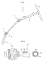
steering device 71 of an automobile. In thesteering device 71, one or a plurality ofintermediate shafts 75 are arranged between aninput shaft 73 connected to asteering wheel 72 and a steering gear 74, and these members are connected by the joints 1'. In thesteering device 71, when vibration is transmitted to thesteering wheel 72 from the wheels (not shown) during traveling, there is a fear of the driver experiencing discomfort and an operational error being induced. Thus, it is necessary for thesteering device 71 to be capable of preventing transmission of vibration to thesteering wheel 72. Conventionally, as a means for absorbing such the vibration, there is provided between theinput shaft 73 and theintermediate shafts 75 anelastic shaft coupling 76 as shown in Fig. 9B (see, for example,JP 1996-133097 A JP 2002-310182 A elastic shaft coupling 76 of Fig. 9B, aninner shaft 76a and anouter shaft 76b are fit-engaged with each other through the intermediation of acushioning member 76c. - It should be noted, however, that if not only the
elastic shaft coupling 76 but also the joints 1' can absorb vibration, it is more effective in cutting off transmission of vibration to thesteering wheel 72. As shown in Figs. 7 and 8, in the above-described joint 1', there is provided apressing portion 21a for axially applying an elastic pressing force to an end portion of thesecond shaft portion 21 constituting theinner member 20, and theretainer 40 is provided with a receivingportion 48 for receiving the pressing force from thepressing portion 21a. However, in a state where theouter member 10 and theinner member 20 are at an operation angle of θ, as shown in Fig. 8, the direction of the vibration transmitted axially from theouter member 10 and the direction in which the elastic action of the pressingmember 21a is exerted differ from each other, so it is impossible to effectively absorb the vibration transmitted from theouter member 10 to theinner member 20. - The present invention has been made in view of the above problem in the prior art. It is an object of the present invention to provide a fixed type constant velocity universal joint suitable for applications where vibration is harmful as in a case of an automotive steering device.
- To achieve the above-mentioned object, according to the present invention, a fixed type constant velocity universal joint includes: an outer member having a spherical inner surface with a plurality of track grooves formed therein; an inner member having a spherical outer surface with a plurality of track grooves formed therein; a ball arranged in a wedge-shaped ball track formed by the track grooves of the outer member and the track grooves of the inner member; and a retainer arranged between the spherical inner surface of the outer member and spherical outer surface of the inner member and adapted to retain the ball, in which the outer member is formed in a multi-layer structure of three or more layers formed of an outside member, one or a plurality of intermediate members, and an inside member, and in which at least one of the intermediate members is formed of an elastic material.
- More specifically, as shown, for example, in Fig. 1, the
outer member 10 is formed in a three-layer structure composed of anoutside member 15, anintermediate member 16, and aninside member 17, with theintermediate member 16 being formed of an elasticmaterial. Instead of providing only oneintermediate member 16, it is also possible to provide a plurality of theintermediate members 16, with at least one of the plurality ofintermediate members 16 being formed of an elastic material. By thus forming theouter member 10 in a multi-layer structure, due to the cushioning action of theintermediate member 16, it is possible to reliably absorb vibration transmitted from whichever of theouter member 10 and theinner member 20. Thus, it is possible to provide the fixed type constant velocity universal joint suitable for applications where vibration is harmful. - When forming the outer member in a multi-layer structure as described above, it is possible to effect torque transmission between the outer member and the inner member by providing an engagement portion on both the inner side of the outside member and the outer side of the inside member.
- In the outer member, the inside member is fit-engaged with the outside member through the intermediation of the intermediate member, and the outside member, the intermediate member, and the inside member are integrally fixed together by a fixing device.
- When fit-engaging the inside member with the outside member through the intermediation of the intermediate member, there is provided a fixing device for integrally fixing together the outside member, the intermediate member, and the inside member to prevent detachment of the intermediate member and the inside member from the outside member. Examples of the fixing device include one which is formed as a member separate from the outside member, or the like, and which is integrally mounted to the outside member to be locked to an end portion of the inside member, and one which is locked to an end portion of the inside member through plastic deformation of a predetermined portion of the outside member.
- While it is desirable to use a rubber material for the elastic material forming the intermediate member from the viewpoint of workability and availability, any other material will do as long as it provides a desired cushioning action.
- Further, when used, in particular, as a constant velocity universal joint for a steering device arranged between the steering wheel and the steering gear of a vehicle, the above-described fixed type constant velocity universal joint effectively provides a vibration absorbing effect as mentioned above, making it possible to prevent vibration of the steering wheel. The steering device may be an electric power steering device (EPS) imparting an assistant force by a motor, or a hydraulic power steering device imparting an assist force through oil pressure.
- In the present invention, the outer member is provided with an elastic member as described above, whereby it is possible to absorb vibration with a simple structure. Thus, it is possible to provide the fixed type constant velocity universal joint suitable for applications where vibration is harmful as in the case of a steering device.
- Fig. 1 is a longitudinal sectional view showing the present invention as applied to a Rzeppa type joint, which is a kind of fixed type constant velocity universal joint;
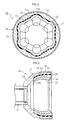
- Fig. 2 is a cross-sectional view of an outer member taken along the line A-A of Fig. 1;
- Fig. 3 is an end view of an opening of the outer member as seen in a direction of the arrow B of Fig. 1;
- Fig. 4 is a cross-sectional view, taken along the line A-A of Fig. 1, of an outer member according to a modification of the present invention;
- Fig. 5 is a longitudinal sectional view of the outer member according to a modification of the present invention;
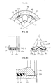
- Figs. 6A through 6C are diagrams showing modifications of a fixing device, in which Fig. 6A is an end view of an opening of the outer member, a left-hand side portion of Fig. 6B being an enlarged longitudinal sectional view of a main portion of the outer member, the right-hand side portion of Fig. 6B is an end view of the opening of the outer member, and Fig. 6C is a longitudinal sectional view of a main portion of the outer member;
- Fig. 7 is a longitudinal sectional view of a conventional fixed type constant velocity universal joint;
- Fig. 8 is an explanatory view illustrating an operation of a conventional fixed type constant velocity universal joint; and
- Figs. 9A and 9B are schematic views of the conventional fixed type constant velocity universal joint as applied to a steering device.
- In the following, a fixed type constant velocity universal joint according to a preferred embodiment of the present invention will be described with reference to Figs. 1 through 6. The components that are the same as those of a conventional joint 1' shown in Figs. 7 and 8 are indicated by the same reference symbols, and a detailed description thereof will be omitted.
- Fig. 1 shows the present invention as applied to a Rzeppa type joint 1 (hereinafter referred to as joint 1) , which is a kind of the fixed type constant velocity universal joint. As shown in Fig. 1, the
joint 1 is mainly composed of anouter member 10, aninner member 20,balls 30, and aretainer 40; theouter member 10 has acup portion 13 formed in a three-layer structure composed of anoutside member 15, anintermediate member 16, and aninside member 17, with theintermediate member 16 being formed of an elastic material. - As shown in Figs. 1 and 2, the
outside member 15 is a member constituting a main body of theouter member 10, and is formed by providing an outer layer portion of thecup portion 13 at an end of afirst shaft portion 11. As shown in Fig. 2, an inner surface of theoutside member 15 is formed in a spherical configuration corresponding to a sphericalinner surface 12 of thecup portion 13, andengagement grooves 15a as engagement portions for engagement with theinside member 17 are provided at positions corresponding to a plurality oftrack grooves 14. - As shown in Figs. 1 and 2, the
intermediate member 16 is a member provided between theoutside member 15 and theinside member 17 and formed of an elastic material, such as rubber or a resin. theintermediate member 16 is formed in a cup-like configuration corresponding to a configuration of a gap between theoutside member 15 and theinside member 17, and is arranged so as to be in intimate contact with the entire inner surface of theoutside member 15 and the entire outer surface of theinside member 17. - As shown in Figs. 1 and 2, the
inside member 17 is a member constituting the sphericalinner surface 12 of thecup portion 13 of theouter member 10. The outer surface of theinside member 17 is formed in a spherical configuration corresponding to the sphericalinner surface 12, and its outer diameter is somewhat smaller than the inner diameter of theoutside member 15. As shown in Fig. 2, on an outer surface of theinside member 17, there are formed, at positions corresponding to the plurality oftrack grooves 14 formed on the inner surface side,ridges 17a as engagement portions for engagement with theengagement grooves 15a of theoutside member 15. Theridges 17a have a width somewhat smaller than a width of theengagement grooves 15a of theoutside member 15, and are formed so as to protrude into theengagement grooves 15a of theoutside member 15 to be engaged with theengagement grooves 15a of theoutside member 15 through the intermediation of theintermediate member 16. With this construction, torque transmission is possible between theoutside member 15 and theinside member 17. - In Figs. 1 through 3,
reference numeral 60 indicates a fixing member as a fixing device, and the fixingmember 60 serves to prevent theintermediate member 16 and theinside member 17 from being detached from theoutside member 15. As shown in Figs. 1 and 3, the fixingmember 60 has acylinder portion 61 to be fit-engaged with the outer side of the opening end portion of theoutside member 15, and a plurality oflock portions 62 extending radially inwards in a tongue-like configuration from positions at the end of thecylinder portion 61 corresponding to thetrack grooves 14 of theouter member 10. As shown in Fig. 1, the depth-side end portion (end portion on the opposite side of the lock portions 62) is inwardly caulked to form a caulkedportion 63, which is engaged with the outer portion of theoutside member 15. As shown in Fig. 3, thelockportions 62 are locked to the respective opening side endportions of theoutside member 15, theintermediate member 16, and theinside member 17 at positions corresponding to engagement positions of theoutside member 15 and theinside member 17. As a result, theoutside member 15, theintermediate member 16, and theinside member 17 are integrally fixed together to form theouter member 10. - As described above, in the
joint 1 of the present invention, theouter member 10 is formed in a three-layer structure by providing theintermediate member 16, which is formed in a cup-like configuration of an elastic material, such as rubber or resin, between theoutside member 15 and theinside member 17, so vibration transmitted from whichever of theouter member 10 and theinner member 20, with theouter member 10 and theinner member 20 being at a predetermined operation angle of θ (see Fig. 8), can be absorbed by thecup portion 13 of theouter member 10. - As described above, the description has been made of one embodiment of the present invention, however the present invention is not restricted to the above-described embodiment but allows various modifications. For example, as shown in Fig. 4, the
engagement grooves 15a of theoutside member 15 and theridges 17a of theinside member 17 may be of any other configuration, such as an arcuate cross-sectional configuration, in correspondence with thetrack grooves 14 of thecup portion 13 as long as it allows torque transmission between theoutside member 15 and theinside member 17. - The configuration of the
intermediate member 16 is not restricted to a cup-like one. For example, as shown in Fig. 5, theintermediate member 16 may be formed in a cylindrical configuration. The cylindricalintermediate member 16 is suitable for a case in which as shown, for example, in Fig. 5, theouter member 10 is composed of the two members of thefirst shaft portion 11 and the cup portion 13 (outer ring). Thefirst shaft portion 11 and the cup portion 13 (outer ring) of Fig. 5 are connected together by an appropriate method, such as screw connection, plastic connection, welding, adhesion, press-fitting, or shrink fitting. In the case of Fig. 5, theinside member 17 may also be formed in a cylindrical configuration, locking the depth-side end portion of theinside member 17 by astep portion 15b provided on the inner surface of theoutside member 15. - As shown in Fig. 6A, the
lock portions 62 of the fixingmember 60 may be formed over an entire periphery of thecylindrical portion 61. In this case, if the fixingmember 60 slides circumferentially relative to theouter member 10, it is always possible to prevent detachment of theintermediate member 16 and theinside member 17. - Further, as shown in Fig. 6B, the fixing device may be formed by a
lock portion 15c formed of an axial notch formed at the opening end of theoutside member 15. As shown in the right-hand side portion of Fig. 6B, thelock portion 15c is formed through formation of the outer configuration of theoutside member 15 in correspondence with the inner configuration thereof. Thelock portion 15c is formed in asmall diameter portion 15d between theengagement grooves 15a, and is locked with the end portions of theintermediate member 16 and theinside member 17 through plastic deformation toward the inner side of theoutside member 15. Apart from the notch formed at the end of theoutside member 15, thelock portion 15c may also be a tongue-like protrusion formed at the end of theoutside member 15 like thelock portions 62 of the fixingmember 60 shown in Figs. 1 and 3. - Further, as shown in Fig. 6C, it is also possible for the fixing device to be formed by a caulked
portion 15e formed through plastic deformation toward the inner side of a part or all of the opening end portion of theoutside member 15. In this case, there is formed aswollen portion 17b, which makes the outer diameter of the opening end portion of theinside member 17 substantially equal to the inner diameter of the opening end portion of theoutside member 15, with the caulkedportion 15e of theoutside member 15 being locked to theswollen portion 17b of theinside member 17. Theintermediate member 16 is arranged in the gap between the depth-side portions of theoutside member 15 and theinside member 17, with the outer diameter of the depth-side portion of theinside member 17 being smaller than the inner diameter of the depth-side portion of theoutside diameter 15. - Furthermore, it is also possible for the
outside member 15, theintermediate member 16, and theinside member 17 to be integrated through baking and sticking theintermediate member 16 to theoutside member 15 and theinside member 17. When theoutside member 15, theintermediate member 16, and theinside member 17 are thus integrated through plastic deformation of theoutside member 15 or baking and sticking theintermediate member 16, the number of components of theouter member 10 is reduced to thereby facilitate the assembly and suppress the production cost as compared with the case in which the fixingmember 60 and theoutside member 15 are formed as separate members. - It suffices for the
outer member 10 to be of a multi-layer structure of three layers or more; when a plurality ofintermediate members 16 are provided, it is possible to form theintermediate members 16 of different kinds of elastic material instead of forming them of the same kind of elastic material. Alternatively, it is also possible to form at least oneintermediate member 16 of an elastic material, while forming the otherintermediate members 16 of a non-elastic material. - While the above-described embodiment of the present invention is applied to a Rzeppa type joint 1, in which the
pressing portion 21a is formed at an end of thesecond shaft portion 21 of theinner member 20 and in which theretainer 40 is provided with a receivingportion 48, the present invention is also applicable to any other fixed type constant velocity universal joint including an undercut free type joint.
Claims (7)
- A fixed type constant velocity universal joint comprising:an outer member having a spherical inner surface with a plurality of track grooves formed therein;an inner member having a spherical outer surface with a plurality of track grooves formed therein;a plurality of balls each arranged in a wedge-shaped ball track formed by the track groove of the outer member and the track groove of the inner member; anda retainer arranged between the spherical inner surface of the outer member and spherical outer surface of the inner member and adapted to retain the balls,wherein the outer member is formed in a multi-layer structure of three or more layers formed of an outside member, one or a plurality of intermediate members, and an inside member, andwherein at least one of the intermediate members is formed of an elastic material.
- A fixed type constant velocity universal joint according to Claim 1, wherein the outside member and the inside member are provided with engagement portions for effecting torque transmission.
- A fixed type constant velocity universal joint according to Claim 1 or 2, further comprising a fixing means for fit-engaging the inside member with the outside member through the intermediate member to integrally fix together the outside member, the intermediate member, and the inside member.
- A fixed type constant velocity universal joint according to Claim 3, wherein the fixing means is equipped with a cylinder portion to be fitted onto an outer side of an opening end portion of the outside member, and a lock portion extending radially inwards from an end portion of the cylinder portion to be locked to an end portion of the inside member.
- A fixed type constant velocity universal joint according to Claim 3, wherein the fixing means is a caulked portion formed through radially inward plastic deformation of an end portion of the outside member to effect locking to an end portion of the inside member.
- A fixed type constant velocity universal joint according to any one of Claims 1 through 5, wherein the elastic material comprises a rubber material.
- A fixed type constant velocity universal joint according to any one of Claims 1 through 6, wherein the fixed type constant velocity universal joint is used in a steering device arranged between a steering wheel and a steering gear of a vehicle.
Applications Claiming Priority (2)
| Application Number | Priority Date | Filing Date | Title |
|---|---|---|---|
| JP2004023977A JP2005214344A (en) | 2004-01-30 | 2004-01-30 | Fixed type uniform motion universal joint |
| PCT/JP2004/018675 WO2005073579A1 (en) | 2004-01-30 | 2004-12-08 | Fixed-type constant velocity universal joint |
Publications (2)
| Publication Number | Publication Date |
|---|---|
| EP1710459A1 true EP1710459A1 (en) | 2006-10-11 |
| EP1710459A4 EP1710459A4 (en) | 2009-07-01 |
Family
ID=34823902
Family Applications (1)
| Application Number | Title | Priority Date | Filing Date |
|---|---|---|---|
| EP04807034A Withdrawn EP1710459A4 (en) | 2004-01-30 | 2004-12-08 | Fixed-type constant velocity universal joint |
Country Status (6)
| Country | Link |
|---|---|
| US (1) | US7771282B2 (en) |
| EP (1) | EP1710459A4 (en) |
| JP (1) | JP2005214344A (en) |
| KR (1) | KR20070001934A (en) |
| CN (1) | CN1906427A (en) |
| WO (1) | WO2005073579A1 (en) |
Cited By (3)
| Publication number | Priority date | Publication date | Assignee | Title |
|---|---|---|---|---|
| DE102007011661A1 (en) * | 2007-03-09 | 2008-09-11 | Zf Lenksysteme Gmbh | steering shaft |
| DE102009040727A1 (en) | 2009-09-09 | 2011-07-21 | SGF Süddeutsche Gelenkscheibenfabrik GmbH & Co. KG, 84478 | Torque transmitting device for shaft arrangement of motor vehicle, has vibration damping unit, and pressurized damper arrangement provided between neighboring segment sections in transmission area |
| US8517844B2 (en) | 2008-11-26 | 2013-08-27 | Sgf Sueddeutsche Gelenkscheibenfabrik Gmbh & Co. Kg | Torque transmitting device |
Families Citing this family (8)
| Publication number | Priority date | Publication date | Assignee | Title |
|---|---|---|---|---|
| BRPI0615878A2 (en) * | 2005-09-13 | 2011-05-31 | Shaft Form Engineering Gmbh | spherical joint and articulated shaft |
| DE102006016841A1 (en) * | 2006-04-07 | 2007-10-18 | Gkn Driveline International Gmbh | Backlash-free constant velocity universal joint |
| WO2010049163A1 (en) | 2008-10-31 | 2010-05-06 | Shaft-Form-Engineering Gmbh | Ball joint and method for the production thereof |
| DE102009015162A1 (en) * | 2009-03-26 | 2010-09-30 | Bayerische Motoren Werke Aktiengesellschaft | Fixed ball joint for use in drive train of motor vehicle, has joint inner ring, which is connected with drive shaft in torque-proof manner, where joint outer ring is provided for connecting output shaft and joint balls provided in ball cage |
| KR101467913B1 (en) * | 2013-09-11 | 2014-12-02 | 한국델파이주식회사 | Constant velocity universal joint |
| JP6347994B2 (en) * | 2014-06-16 | 2018-06-27 | Ntn株式会社 | Method for manufacturing outer joint member of constant velocity universal joint and outer joint member |
| JP6320855B2 (en) * | 2014-06-18 | 2018-05-09 | Ntn株式会社 | Method for manufacturing outer joint member of constant velocity universal joint and outer joint member |
| CN104806653A (en) * | 2015-04-28 | 2015-07-29 | 浙江龙虎锻造有限公司 | Ball cage type equal speed universal joint |
Family Cites Families (18)
| Publication number | Priority date | Publication date | Assignee | Title |
|---|---|---|---|---|
| US2875599A (en) * | 1955-04-29 | 1959-03-03 | Benjamin F Gregory | Universal joint and lubricant retaining housing therefor |
| US3424473A (en) * | 1967-01-05 | 1969-01-28 | Int Harvester Co | Uniform response tiltable steering arrangement |
| FR2172580A5 (en) * | 1972-02-18 | 1973-09-28 | Glaenzer Spicer Sa | |
| DE3017757C2 (en) | 1980-05-09 | 1982-07-01 | Löhr & Bromkamp GmbH, 6050 Offenbach | Storage arrangement |
| US4549274A (en) | 1983-07-11 | 1985-10-22 | Honeywell Inc. | Distributed electric power demand control |
| JPS6035920U (en) * | 1983-08-18 | 1985-03-12 | 富士重工業株式会社 | Constant velocity joint ball prevention structure |
| DE3709768A1 (en) * | 1987-03-25 | 1988-10-13 | Freudenberg Carl Fa | ANGLE MOVABLE SHAFT COUPLING |
| DE3732471A1 (en) | 1987-09-23 | 1989-04-13 | Siemens Ag | ELECTRIC COMPRESSED GAS CIRCUIT BREAKER, ESPECIALLY SF (DOWN ARROW) 6 (DOWN ARROW) HIGH VOLTAGE CIRCUIT BREAKER |
| JPH01115021U (en) * | 1988-01-28 | 1989-08-02 | ||
| JPH0753891B2 (en) | 1989-06-26 | 1995-06-07 | 川崎製鉄株式会社 | Manufacturing method of high strength cold rolled steel sheet for deep drawing with small in-plane anisotropy |
| JPH0328325U (en) * | 1989-07-28 | 1991-03-20 | ||
| DE4142359C2 (en) | 1991-05-31 | 1996-12-12 | Ntn Toyo Bearing Co Ltd | Outer ring for a vibration-protected homokinetic joint |
| JPH0545252A (en) | 1991-08-15 | 1993-02-23 | Mazda Motor Corp | Shifting inspection method for transmission |
| JP2560556Y2 (en) * | 1991-11-20 | 1998-01-26 | 株式会社ユニシアジェックス | Constant velocity joint |
| JPH0687141A (en) | 1992-07-23 | 1994-03-29 | Yuji Kojima | Production equipment of molded article and manufacture thereof |
| JPH0687141U (en) * | 1993-06-08 | 1994-12-20 | 三菱自動車工業株式会社 | Constant velocity joint release structure |
| JP3639258B2 (en) * | 2001-02-21 | 2005-04-20 | ジー・ケー・エヌ・ドライブライン・ドイチェランド・ゲゼルシャフト・ミット・ベシュレンクテル・ハフツング | Outer joint part for constant speed joint |
| JP4219583B2 (en) | 2001-10-26 | 2009-02-04 | Ntn株式会社 | Fixed type constant velocity universal joint |
-
2004
- 2004-01-30 JP JP2004023977A patent/JP2005214344A/en not_active Withdrawn
- 2004-12-08 CN CNA2004800411427A patent/CN1906427A/en active Pending
- 2004-12-08 KR KR1020067015024A patent/KR20070001934A/en not_active Withdrawn
- 2004-12-08 WO PCT/JP2004/018675 patent/WO2005073579A1/en not_active Ceased
- 2004-12-08 EP EP04807034A patent/EP1710459A4/en not_active Withdrawn
- 2004-12-08 US US10/585,941 patent/US7771282B2/en not_active Expired - Fee Related
Cited By (4)
| Publication number | Priority date | Publication date | Assignee | Title |
|---|---|---|---|---|
| DE102007011661A1 (en) * | 2007-03-09 | 2008-09-11 | Zf Lenksysteme Gmbh | steering shaft |
| US8517844B2 (en) | 2008-11-26 | 2013-08-27 | Sgf Sueddeutsche Gelenkscheibenfabrik Gmbh & Co. Kg | Torque transmitting device |
| DE112009004635B4 (en) * | 2008-11-26 | 2020-06-18 | Süddeutsche Gelenkscheibenfabrik Gesellschaft mit beschränkter Haftung & Co. KG | Torque transmission device and shaft assembly with a torque transmission device |
| DE102009040727A1 (en) | 2009-09-09 | 2011-07-21 | SGF Süddeutsche Gelenkscheibenfabrik GmbH & Co. KG, 84478 | Torque transmitting device for shaft arrangement of motor vehicle, has vibration damping unit, and pressurized damper arrangement provided between neighboring segment sections in transmission area |
Also Published As
| Publication number | Publication date |
|---|---|
| US7771282B2 (en) | 2010-08-10 |
| US20070280778A1 (en) | 2007-12-06 |
| KR20070001934A (en) | 2007-01-04 |
| JP2005214344A (en) | 2005-08-11 |
| WO2005073579A1 (en) | 2005-08-11 |
| CN1906427A (en) | 2007-01-31 |
| EP1710459A4 (en) | 2009-07-01 |
Similar Documents
| Publication | Publication Date | Title |
|---|---|---|
| US7771282B2 (en) | Fixed type constant velocity universal joint | |
| JP2003130082A (en) | Fixed type constant velocity universal joint | |
| US7704149B2 (en) | Fixed type constant velocity joint | |
| JPH0942304A (en) | Constant velocity universal joint | |
| WO2017184918A1 (en) | Cross groove constant velocity joints for a propeller shaft | |
| JP2005096541A (en) | Intermediate shaft device for vehicle steering device | |
| US20010018368A1 (en) | Shaft assembly for ball-type constant velocity joints | |
| WO2005078302A1 (en) | Constant velocity universal joint | |
| JP2005221033A (en) | Fixed type constant velocity universal joint | |
| JP2012233550A (en) | Ball type universal joint | |
| JP5133203B2 (en) | Sliding constant velocity universal joint and manufacturing method thereof | |
| EP1666749B1 (en) | Constant velocity universal joint | |
| WO2005078300A1 (en) | Constant velocity universal joint | |
| JP4339144B2 (en) | Fixed type constant velocity universal joint | |
| US20080051203A1 (en) | Fixed Type Constant Velocity Joint | |
| US12379000B2 (en) | Constant velocity joint with staking features | |
| JP2008261423A (en) | Telescopic rotation transmission shaft | |
| JP4298529B2 (en) | Fixed type constant velocity universal joint | |
| JP2002250359A (en) | Constant velocity universal joint | |
| WO2026053674A1 (en) | Hub assembly | |
| JP6253933B2 (en) | Constant velocity universal joint | |
| JPH0747617Y2 (en) | Elastic coupling | |
| JP2005225458A (en) | Steering device | |
| JPS6132845Y2 (en) | ||
| JP4298528B2 (en) | Fixed type constant velocity universal joint |
Legal Events
| Date | Code | Title | Description |
|---|---|---|---|
| PUAI | Public reference made under article 153(3) epc to a published international application that has entered the european phase |
Free format text: ORIGINAL CODE: 0009012 |
|
| 17P | Request for examination filed |
Effective date: 20060719 |
|
| AK | Designated contracting states |
Kind code of ref document: A1 Designated state(s): AT BE BG CH CY CZ DE DK EE ES FI FR GB GR HU IE IS IT LI LT LU MC NL PL PT RO SE SI SK TR |
|
| DAX | Request for extension of the european patent (deleted) | ||
| A4 | Supplementary search report drawn up and despatched |
Effective date: 20090529 |
|
| 17Q | First examination report despatched |
Effective date: 20100429 |
|
| GRAP | Despatch of communication of intention to grant a patent |
Free format text: ORIGINAL CODE: EPIDOSNIGR1 |
|
| STAA | Information on the status of an ep patent application or granted ep patent |
Free format text: STATUS: THE APPLICATION IS DEEMED TO BE WITHDRAWN |
|
| 18D | Application deemed to be withdrawn |
Effective date: 20130305 |