EP1710449A1 - Single acting locking cylinder - Google Patents
Single acting locking cylinder Download PDFInfo
- Publication number
- EP1710449A1 EP1710449A1 EP05027442A EP05027442A EP1710449A1 EP 1710449 A1 EP1710449 A1 EP 1710449A1 EP 05027442 A EP05027442 A EP 05027442A EP 05027442 A EP05027442 A EP 05027442A EP 1710449 A1 EP1710449 A1 EP 1710449A1
- Authority
- EP
- European Patent Office
- Prior art keywords
- locking
- cylinder
- spindle
- rotation
- movable
- Prior art date
- Legal status (The legal status is an assumption and is not a legal conclusion. Google has not performed a legal analysis and makes no representation as to the accuracy of the status listed.)
- Granted
Links
- 230000000903 blocking effect Effects 0.000 claims abstract description 7
- 239000012530 fluid Substances 0.000 claims description 12
- 238000013461 design Methods 0.000 description 7
- 238000010276 construction Methods 0.000 description 4
- 238000011161 development Methods 0.000 description 4
- 238000007789 sealing Methods 0.000 description 4
- 238000013459 approach Methods 0.000 description 3
- 238000006073 displacement reaction Methods 0.000 description 3
- 238000004891 communication Methods 0.000 description 2
- 230000006835 compression Effects 0.000 description 2
- 238000007906 compression Methods 0.000 description 2
- 230000008878 coupling Effects 0.000 description 2
- 238000010168 coupling process Methods 0.000 description 2
- 238000005859 coupling reaction Methods 0.000 description 2
- 230000006378 damage Effects 0.000 description 2
- 238000010586 diagram Methods 0.000 description 2
- 230000003068 static effect Effects 0.000 description 2
- 230000003750 conditioning effect Effects 0.000 description 1
- 230000007423 decrease Effects 0.000 description 1
- 230000003116 impacting effect Effects 0.000 description 1
- 238000009434 installation Methods 0.000 description 1
- 230000000717 retained effect Effects 0.000 description 1
- 238000005096 rolling process Methods 0.000 description 1
- 238000012546 transfer Methods 0.000 description 1
Images


Classifications
-
- F—MECHANICAL ENGINEERING; LIGHTING; HEATING; WEAPONS; BLASTING
- F15—FLUID-PRESSURE ACTUATORS; HYDRAULICS OR PNEUMATICS IN GENERAL
- F15B—SYSTEMS ACTING BY MEANS OF FLUIDS IN GENERAL; FLUID-PRESSURE ACTUATORS, e.g. SERVOMOTORS; DETAILS OF FLUID-PRESSURE SYSTEMS, NOT OTHERWISE PROVIDED FOR
- F15B15/00—Fluid-actuated devices for displacing a member from one position to another; Gearing associated therewith
- F15B15/20—Other details, e.g. assembly with regulating devices
- F15B15/26—Locking mechanisms
- F15B15/262—Locking mechanisms using friction, e.g. brake pads
- F15B15/264—Screw mechanisms attached to the piston
Definitions
- the invention relates to a locking cylinder according to the preamble of claim 1.
- Such locking cylinders are the subject of four not yet published German patent applications of the protected rights holder, under the official file number 103 56 597.3 . 103 56 598.1 . 13 56 596.5 such as 10 2004 022 203.7 are guided.
- the present patent is a further development of the above-mentioned objects of the application, so that for the sake of simplicity and to avoid repetition of the content of these four patent applications is taken in full at this point.
- the relative to the cylinder movable locking body is pressed by means of the spring force of the spring against the counter locking body delimiting and rotating about the axis of rotation of the spindle step or tooth-shaped control edge, wherein the movable relative to the cylinder locking body and the step or the tooth are designed to be coordinated with each other such that the locking body which is movable relative to the cylinder can engage or engage in its locking position when the spindle is rotated in its first direction of rotation on the step or on the tooth in order to provide a mechanical locking to cause the spindle and wherein the control edge can run at a rotation of the spindle in its opposite, second rotational direction, substantially unhindered on the relative to the cylinder movable locking body along.
- the spindle is thus always mechanically unlocked in this second direction of rotation.
- the counter-locking body preferably the locking body rotatably connected to the spindle locking body, at least one outwardly open locking recess into which acted upon by the spring force of the spring and can engage relative to the cylinder movable locking body.
- a particularly simple, space-saving and cost-effective and reliable construction can be achieved if the locking recess with a control edge-containing outlet slope, such as a ramp or inclined plane, is designed for the relative to the cylinder movable locking body.
- a control edge-containing outlet slope such as a ramp or inclined plane
- the locking recess has a trapezoidal cross section in the circumferential direction.
- a locking recess can be produced in a particularly simple and cost-effective manner.
- a particularly space-saving design in conjunction with advantageous possibilities of further improved operational safety can be achieved in that the locking recess is designed axially, ie in the longitudinal direction of the cylinder, open to the outside.
- the locking recess is provided in a hole-disc-shaped approach, which is rotatably connected to the spindle.
- the reliability can be further increased if a plurality of locking recesses in the circumferential direction with respect to the axis of rotation of the spindle and spaced from each other. It is particularly advantageous if at least four, preferably at least six locking recesses are provided.
- the relative to the cylinder movable locking body is mounted parallel to the axis of rotation of the spindle axially displaceable on or in a head of the cylinder and in its locking position in an axially outwardly open locking recess or in several axially outward open locking recesses engages.
- the locking bolt may advantageously be designed as a cylinder pin, in particular as a circular cylindrical bolt.
- a plurality of, preferably two, locking bodies movable relative to the cylinder are designed as separately movable locking bolts.
- Such locking bolts are simple and inexpensive to produce and require only a minimal installation and switch room, so that the space gained can be used to advantage for other elements and / or tasks or an overall smaller and lighter locking cylinder can be provided.
- only comparatively small locking and unlocking forces are required.
- the locking cylinder in the region of the locking unit can be made more space-saving or lighter overall. Also can be achieved by the aforementioned measures significantly reduced locking and unlocking.
- a plurality of, preferably two, locking bodies movable relative to the cylinder are movable separately and independently of one another.
- the relative to the cylinder movable locking body by means of a fluid working means against the spring force of the spring from its locking position can be converted into an unlocking position in which the spindle is rotatable about its axis of rotation.
- the relatively movable relative to the cylinder locking body and thus also the spindle can be hydraulically unlocked, so that when a pressurization of the piston with fluid pressure medium, the piston can be moved with simultaneous rotation of the spindle relative to the cylinder.
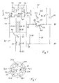
- the locking cylinder 20 shown in Figure 1 comprises a cylinder 21 and a longitudinally slidably mounted therein piston 22.
- the piston 22 is sealed relative to the cylinder inner wall by a ring seal 68 and is on its in the direction of the longitudinal axis 29 of the cylinder 21 facing away from each other pages 44, 46 by a fluid pressure medium, preferably oil, acted upon to allow a pressure-medium-assisted movement of the piston 22 in a direction of unlocking referred to as the second direction or unlocking direction 27 or in a direction also referred to as the first direction of extension 28.
- a fluid pressure medium preferably oil
- the piston 22 is fixedly connected to a piston rod 23, which, starting from its end face 44 coaxial with Cylinder longitudinal axis 29 extends.
- the cylinder 20 is closed at its the free end 67 of the spindle 35 side by a piston rod 23 receiving cover 30.
- the cylinder 21 is fixedly connected to a step-shaped projection 66. This is in turn completed by a cylinder bottom 53 forming lid or head 31.
- the piston 22 forms a projection 32 which is non-rotatably connected to the piston rod 23.
- the piston 22 is designed as a tubular hollow body and has an internal thread 34, also referred to as a piston thread. This is engaged with an external thread 36, also referred to as a spindle thread, of a spindle 35 on which the piston 22 is guided.
- the internal thread 34 of the piston 22 and the external thread 36 of the spindle 35 are preferably designed as eight-speed trapezoidal coarse thread, which together form a non-self-locking thread 37, which is designed here right-handed.
- the piston rod 23 For attachment of the locking cylinder 20, the piston rod 23 at its free end a here designed with an eyelet fastener 25, and a correspondingly shaped fastener 26 is mounted opposite to the head 31 of the cylinder 21.
- the pressure medium can be fed via the channels 48 and 49 on both sides 44 and 46 of the piston 22 into a first working chamber 45 and into a second working chamber 33 in order to achieve a movement of the piston 22 along the cylinder 21 in the retraction direction 27 or in the extension direction 28 can.
- the first working chamber 45 against the second working chamber 33 sealed via the annular seal 68 of the piston 22.
- the plate springs 134 and the plate springs 136 are each alternately successively preferably arranged such that in each case the spring travel of each plate spring 134, 136 is available for a resilient mounting of the spindle 35.
- the plate springs 134, 136 are selected with regard to their spring characteristics and arrangement such that in the regular driving operation, when the piston 22 is moved in the retraction direction 27, the thereby transmitted via the non-self-locking thread 37 and the spindle 35 dynamic resultant forces, d. H. be compensated so that the support body 124 is always lifted from the head 31 of the cylinder bottom of the cylinder 21.
- the flange-shaped projection 65 is provided on the transverse to the axis of rotation 43 of the spindle 35 extending wall part 79 or perforated disc part 141 with here a total of six locking recesses 38.1 to 38.6.
- the locking recesses 38.1 to 38.6 are each arranged at the same angular intervals on an imaginary circumferential circle 78 such that two locking recesses are arranged diametrically opposite each other.
- each locking recess 38.1 to 38.6 has a trapezoidal cross section 139 in the sectional plane shown in FIG.
- a stepped or tooth-shaped control edge 78 is formed, which is characterized in the view of Figure 3 by a dash-dotted circle concentric with the axis of rotation 43 of the spindle 35 is arranged. A part of this control edge 78 is clearly visible in the cross section according to FIG.
- Each locking recess 38; 38.1 to 38.6 is designed with conically inwardly tapering wall portions 70 and serves to receive outwardly conically tapered wall parts 72 of locking bolt 40; 40.1, 40.2.
- the conical tapered wall parts 72 having free end 57 of the respective locking pin 40 is preferably designed so matched to the locking recesses 38 in the region of their conically tapered wall parts 70, that a fürströmspalt 71 is formed for the pressure medium.
- This fürströmspalt 71 is in fluid communication with a gap 91 which is arranged in the region of the radial edges of both the flange-shaped projection 65 and the opposite part of the head 31 of the cylinder 21.
- This gap 91 is in fluid communication with a switching channel 47, which in turn Fluid connection with channels 48 and 49 can be brought, via which the piston 22 can be acted upon on its respective sides 44 and 46 with pressure medium.
- the locking bolts 40 are designed cross-sectionally closed in the region of their free ends 57.
- Each locking bolt 40 is designed as a preferably elongated cylinder pin 69 rotationally symmetrical to its longitudinal axis 74.
- Each locking bolt 40 has a circular cylindrical outer contour 50 and a circular cylindrical inner contour, so it is designed as a rotary hollow body.
- Each locking bolt 40 also has a circular cylindrical recess 92 which is designed with parallel to the longitudinal axis 74 of the respective locking bolt 40 delimiting wall parts and which is open to the head 31 of the cylinder 21 opposite end 56 to the outside. This recess 92 serves to receive and lateral support of a designed as a compression spring spring 39.
- the spring 39 is supported with one of its ends 95 on an inner surface 94 of a radially inwardly extending support and abutment surface 60 of the locking bolt 40.
- the other end 96 of the spring 39 is supported on an inner surface of a corresponding support and contact stage 76 of the head 31 of the cylinder 21.
- a radially outwardly extending abutment and counter-sealing surface 98 is provided for the locking bolt 40, which is arranged perpendicular to the wall portions bounding the bearing recess 75. Every locking bolt 40 has at its head or spring-side end 59 on a ring end edge 99, which is designed with a circumferential annular sealing surface 97 and in the unlocking 27 of the respective locking bolt 40 has.
- This annular sealing surface 97 is sealingly against the likewise circumferential abutment and counter-sealing surface 98 of the head 31 of the cylinder 21, when the respective locking pin 40 has been transferred to a loading with the force exerted by the pressure medium in unlocking 27 compressive forces in its unlocked position. Under the then effective pressure forces a seal is achieved there, so that no leakage of pressure fluid along the outer surfaces of the respective locking bolt 40 occurs.
- the abutment and Abdichtalle construction 96 advantageously limits the respective Entriegelungshub the locking pin 40th
- Each locking bolt 40 is slidably mounted parallel to the axis of rotation 43 of the spindle 35 with little play in the cylindrical inner contour 98 having bore or bearing recess 75, so starting from the locking position 41 shown in Figures 1 and 2 by means of the pressure medium in extension or Unlocking direction 28 against the spring forces of the spring 39 are moved to its unlocked position, or vice versa after pressure relief in the region of its free locking end 57 of its unlocked position automatically, ie by the force exerted by the respective spring 39 on the respective locking pin 40 return spring forces, be transferred back into its locking position 41.
- the bearing recess 75 thus has an inner diameter which is slightly larger than the outer diameter of the locking bolt 40.
- the locking bolt 40 has at its free end 57 a perpendicular to its longitudinal axis 74 arranged active surface 58 on which the fluid pressure medium can act to transfer the locking pin 40, starting from the locking position 41 shown in Figure 2 in an unlocking position, in which he is out of engagement with the locking recesses 38.1 to 38.6, so no rotation of the spindle 35 in its first direction of rotation 51 is no longer blocked.
- the oil located in the associated locking recesses 38 is displaced via the switching channel 47 into the return channel 87.
- FIG. 5 is a hydraulic circuit diagram is illustrated, with particularly advantageous control means and ways are used. It is provided as a load-holding Senkbrems means 150 designated load holding Senkbrems valve, which causes when pressurizing the piston 22 on its second side 44 with the in the second working chamber 45 pressure fluid to form a working pressure, the displacement of the Piston 22 causes in a direction of retraction also referred to as the second direction 27, at the same time in the first working chamber 33 on the first side 46 of the piston 22, a counter-pressure exerted by the pressure medium located in the first working chamber 33 acts. This counter-pressure is less than the working pressure in the second working chamber 45, so that an uncontrolled advance of the piston 22 in the second direction 27 is avoided.
- load-holding Senkbrems means 150 designated load holding Senkbrems valve
- the load-holding lowering brake means 150 blocks a return flow of the pressure medium from the working chamber 33, so that the piston 22 is held securely in the desired stroke position by the pressure medium in the working chamber 33.
- the load hold counterbalance valve 150 has an inlet 153, an outlet 154, and a pressure fluid control port 155, the inlet 153 being fluidly connected to the first working chamber 33 via the channel 49.
- the control port 155 of the load-holding lowering valve 150 is fluidly connected to the return passage 87.
- a gearströmsperrkar 156 is fluidly connected, which allows a flow of the pressure medium from the outlet 154 to the inlet 153, but blocks in the opposite direction.
- supply channel 86 branches off into the channel 55 opening channel in which a blocking in this direction check valve 82 is arranged.
- the channel 48 and the switching channel 88 return channel 87 branches off also into the channel 55 emptying channel, in which also a blocking in this direction check valve 83 is arranged.
- the locking cylinder 20 shown in the figures is designed for locking under pressure. This means that the locking cylinder 20 for moving or lifting a not closer shown in the figures.
- Load in the extension direction 27 is used. Act through the to be moved or lifted load on the piston rod 23 against the extension direction 28 acting compressive forces. If the piston rod 23 is to be held under load in any desired position in any desired lifting or extension position, the piston rod 23 is in a stable position with its piston 22 in the desired lifting or extended position by the load-holding lowering valve 150 kept hydraulically secured to the cylinder 21.
- a kind of pawl mechanism 54 is thus realized, by means of which a mechanical locking of the spindle 35 in a first direction of rotation 51 about its axis of rotation 43 is reached, while the spindle 35 in its opposite second direction of rotation 52 about its axis of rotation 43 substantially free is movable or remains, in particular to allow movement of the piston 22 along the cylinder 21, here in the extension direction 28.
- the invention is not only applicable to pressure-locking locking cylinders, but of course also in lock locking on locking cylinders.
- the load-holding counterbalance valve 150 would not be associated with the flow channel 86, as shown in FIG. 5, but would be associated with the return channel 87.
- the outlet 154 of the load-holding lowering valve 150 would be fluidly connected to the return passage 87 and the inlet 153 of the load-holding lowering valve 150 would be fluidly connected to the channel 48 opening into the second working chamber 45.
- the switching channel 47 would then not open into the opening into the second working chamber 45 channel 48, but the switching channel 47 in the opening into the first working chamber 33 channel 49. The rest of the construction could remain unchanged.
- the pressure medium can then flow from the channel 86 via the flow restrictor 173, which is continuous in this direction, into the channel 49, which in turn opens into the first working chamber 33.
- the piston 22 is acted upon by pressure on its second side 46, so that a force in the extension direction 28 acts on the piston 22.
- the here designated return channel 87 channel is acted upon with pressure medium, d. H. It is fed by means of the pump not shown in detail by the return passage 87, a pressure medium. This increases the pressure in the downstream channels, i. H. in the switching channel 88 for the load-holding Senkbrems valve 150, in the switching channel 47 for the hydraulic actuation of the locking pin 40 and in the opening into the second working chamber 45 channel 48 at.
- the load-holding lowering brake valve 150 is adjusted by a spring pressure so that it opens only above a certain pressure, from which therefore the pressure medium can flow from the inlet 153 to the outlet 154 of the load-holding Senkbrems valve 150.
Abstract
Description
Die Erfindung betrifft einen Verriegelungszylinder gemäß dem Oberbegriff des Anspruches 1.The invention relates to a locking cylinder according to the preamble of claim 1.
Derartige Verriegelungszylinder sind Gegenstand von vier noch nicht veröffentlichten
Bei bestimmten Einsatzfällen von mechanisch verriegelbaren Verriegelungszylindern kann es erforderlich sein, dass bei verriegelter Spindel der Kolben relativ zu dem Zylinder in Einfahrrichtung oder in Ausfahrrichtung durch äußere Kräfte bewegt werden muss. Beispielsweise kann es erwünscht sein, dass bei einer Verriegelung nur auf Druck, d. h. bei einer mechanischen Verriegelung des Kolbens relativ zu dem Zylinder in Einfahrrichtung, dennoch der Kolben relativ zu dem Zylinder in Ausfahrrichtung herausgezogen bzw. mit herausgezogen werden kann. Dies ist bei den vorerwähnten Verriegelungszylindern nicht bzw. nicht ohne ein erhebliches Betriebsrisiko möglich.In certain cases of use of mechanically lockable locking cylinders, it may be necessary for the piston to be moved relative to the cylinder in the retraction direction or in the extension direction by external forces when the spindle is locked. For example, it may be desirable that in a locking only to pressure, ie in a mechanical locking of the piston relative to the cylinder in the retraction, yet the piston relative to the cylinder can be pulled out in the extension or pulled out with. This is not possible or not without a significant operational risk in the aforementioned locking cylinders.
Ferner ist es bei einem Einsatz der hydraulischen Elemente und Anschlusskonfigurationen, wie insbesondere in der vorerwähnten Patentanmeldung mit dem amtlichen Aktenzeichen 103 56 596.5 beschrieben, in Verbindung mit bestimmten hydraulischen Schalt- und Leitungselementen denkbar, dass es unter Last zu einer Bewegung des Kolbens relativ zu dem Zylinder kommen kann, obwohl die Spindel mechanisch verriegelt ist. Dies würde ebenfalls ein erhebliches Betriebsrisiko bedeuten.Furthermore, when using the hydraulic elements and connection configurations, as described in particular in the aforementioned patent application with the official file number 103 56 596.5, conceivable in connection with certain hydraulic switching and line elements that under load to a movement of the piston relative to the Cylinder can come, although the spindle is mechanically locked. This would also mean a significant operational risk.
Es ist deshalb eine Aufgabe der Erfindung, einen Verriegelungszylinder zur Verfügung zu stellen, der auch bei speziellen Anforderungen hinsichtlich Einsatz und Funktion sowie bei einfacher und platzsparender Konstruktion eine hohe Betriebssicherheit ermöglicht.It is therefore an object of the invention to provide a locking cylinder available, which allows high reliability even with special requirements in terms of use and function and in a simple and space-saving design.
Diese Aufgabe wird durch die Merkmale des Anspruches 1, insbesondere dadurch gelöst, dass ein den relativ zu dem Zylinder bewegbaren Verriegelungskörper enthaltender Sperrklinkenmechanismus vorgesehen ist, mittels dessen eine mechanische Blockierung bzw. Verriegelung der Spindel in einer ersten Drehrichtung um ihre Drehachse erreichbar ist, während bzw. und wobei die Spindel in einer entgegengesetzten zweiten Drehrichtung um ihre Drehachse bewegbar ist bzw. bleibt, um eine Bewegung des Kolbens längs des Zylinders zu ermöglichen.This object is achieved by the features of claim 1, in particular by providing a pawl mechanism containing the locking body movable relative to the cylinder, by means of which a mechanical locking or locking of the spindle in a first direction of rotation about its axis of rotation can be achieved, while or and wherein the spindle is movable in an opposite, second direction of rotation about its axis of rotation to allow movement of the piston along the cylinder.
In konkreter Ausgestaltung kann vorgesehen sein, dass der relativ zu dem Zylinder bewegbare Verriegelungskörper mithilfe der Federkraft der Feder gegen eine den Gegenverriegelungskörper begrenzende und um die Drehachse der Spindel umlaufende stufen- bzw. zahnförmige Steuerkante angedrückt ist, wobei der relativ zu dem Zylinder bewegbare Verriegelungskörper und die Stufe bzw. der Zahn derart aufeinander abgestimmt gestaltet sind, dass der relativ zu dem Zylinder bewegbare Verriegelungskörper bei einer Drehung der Spindel in ihrer ersten Drehrichtung an der Stufe bzw. an dem Zahn in seiner Verriegelungsstellung einrasten bzw. anschlagen kann, um eine mechanische Verriegelung der Spindel zu bewirken und wobei die Steuerkante bei einer Drehung der Spindel in ihrer entgegengesetzten, zweiten Drehrichtung, im Wesentlichen ungehindert an dem relativ zu dem Zylinder beweglichen Verriegelungskörper entlang laufen kann. Die Spindel ist also in dieser zweiten Drehrichtung stets mechanisch entriegelt.In a concrete embodiment, it may be provided that the relative to the cylinder movable locking body is pressed by means of the spring force of the spring against the counter locking body delimiting and rotating about the axis of rotation of the spindle step or tooth-shaped control edge, wherein the movable relative to the cylinder locking body and the step or the tooth are designed to be coordinated with each other such that the locking body which is movable relative to the cylinder can engage or engage in its locking position when the spindle is rotated in its first direction of rotation on the step or on the tooth in order to provide a mechanical locking to cause the spindle and wherein the control edge can run at a rotation of the spindle in its opposite, second rotational direction, substantially unhindered on the relative to the cylinder movable locking body along. The spindle is thus always mechanically unlocked in this second direction of rotation.
Gemäß einer vorteilhaften Ausgestaltung kann vorgesehen sein, dass der Gegen-Verriegelungskörper, vorzugsweise der mit der Spindel drehfest verbundene Verriegelungskörper, wenigstens eine nach außen offene Verriegelungsausnehmung aufweist, in die der mittels der Federkraft der Feder beaufschlagte und relativ zu dem Zylinder bewegliche Verriegelungskörper eingreifen kann.According to an advantageous embodiment it can be provided that the counter-locking body, preferably the locking body rotatably connected to the spindle locking body, at least one outwardly open locking recess into which acted upon by the spring force of the spring and can engage relative to the cylinder movable locking body.
Eine besonders einfache, platzsparende und kostengünstige sowie betriebssichere Konstruktion kann erreicht werden, wenn die Verriegelungsausnehmung mit einer eine Steuerkante enthaltenden Auslaufschräge, beispielsweise einer Rampe bzw. schiefen Ebene, für den relativ zu dem Zylinder beweglichen Verriegelungskörper gestaltet ist.A particularly simple, space-saving and cost-effective and reliable construction can be achieved if the locking recess with a control edge-containing outlet slope, such as a ramp or inclined plane, is designed for the relative to the cylinder movable locking body.
Ferner kann vorgesehen sein, dass die Verriegelungsausnehmung in Umfangsrichtung einen trapezförmigen Querschnitt aufweist. Dadurch lässt sich eine derartige Verriegelungsausnehmung besonders einfach und kostengünstig herstellen. Eine besonders platzsparende Konstruktion in Verbindung mit vorteilhaften Möglichkeiten einer weiter verbesserten Betriebssicherheit kann dadurch erreicht werden, dass die Verriegelungsausnehmung axial, also in Längsrichtung des Zylinders, nach außen offen gestaltet ist.Furthermore, it can be provided that the locking recess has a trapezoidal cross section in the circumferential direction. As a result, such a locking recess can be produced in a particularly simple and cost-effective manner. A particularly space-saving design in conjunction with advantageous possibilities of further improved operational safety can be achieved in that the locking recess is designed axially, ie in the longitudinal direction of the cylinder, open to the outside.
Es ist ferner zweckmäßig, wenn die Verriegelungsausnehmung in einem lochscheibenförmigen Ansatz versehen ist, der drehfest mit der Spindel verbunden ist.It is also useful if the locking recess is provided in a hole-disc-shaped approach, which is rotatably connected to the spindle.
Die Betriebssicherheit lässt sich weiter erhöhen, wenn mehrere Verriegelungsausnehmungen in Umfangsrichtung bezogen auf die Drehachse der Spindel und beabstandet zueinander angeordnet sind. Dabei ist es besonders vorteilhaft, wenn wenigstens vier, vorzugsweise wenigstens sechs Verriegelungsausnehmungen vorgesehen sind.The reliability can be further increased if a plurality of locking recesses in the circumferential direction with respect to the axis of rotation of the spindle and spaced from each other. It is particularly advantageous if at least four, preferably at least six locking recesses are provided.
Von besonderem Vorteil ist es, wenn der relativ zu dem Zylinder bewegliche Verriegelungskörper parallel zu der Drehachse der Spindel axial verschieblich an bzw. in einem Kopf des Zylinders gelagert ist und in seiner Verriegelungsstellung in eine axial nach außen offene Verriegelungsausnehmung bzw. in mehrere axial nach außen offene Verriegelungsausnehmungen eingreift.It is particularly advantageous if the relative to the cylinder movable locking body is mounted parallel to the axis of rotation of the spindle axially displaceable on or in a head of the cylinder and in its locking position in an axially outwardly open locking recess or in several axially outward open locking recesses engages.
Eine besonders platzsparende, kostengünstige und betriebssichere Konstruktion kann erreicht werden, wenn der relativ zu dem Zylinder bewegliche Verriegelungskörper als Verriegelungsbolzen gestaltet ist. Der Verriegelungsbolzen kann vorteilhaft als Zylinderbolzen, insbesondere als kreiszylindrischer Bolzen gestaltet sein.A particularly space-saving, inexpensive and reliable construction can be achieved if the relative to the cylinder movable locking body is designed as a locking bolt. The locking bolt may advantageously be designed as a cylinder pin, in particular as a circular cylindrical bolt.
Von besonderem Vorteil ist es ferner, wenn mehrere, vorzugsweise zwei relativ zu dem Zylinder bewegliche Verriegelungskörper als separat bewegliche Verriegelungsbolzen gestaltet sind. Dadurch kann ein Verklemmen oder Verkanten bei der Verriegelung vermieden werden. Derartige Verriegelungsbolzen sind einfach und kostengünstig herstellbar und beanspruchen nur einen minimalen Einbau- und Schaltraum, so dass der gewonnene Platz vorteilhaft für andere Elemente und/oder Aufgaben genutzt werden kann oder ein insgesamt kleinerer und leichterer Verriegelungszylinder bereitgestellt werden kann. Es werden außerdem nur vergleichsweise kleine Ver- und Entriegelungskräfte benötigt. Dadurch kann der Verriegelungszylinder im Bereich der Verriegelungseinheit insgesamt platzsparender bzw. leichter ausgeführt werden. Auch lassen sich durch die vorgenannten Maßnahmen deutlich reduzierte Ver- bzw. Entriegelungszeiten erreichen. Schließlich werden bei einem Einsatz von separat beweglichen Verriegelungsbolzen keine umlaufenden Dichtungen zwischen diesen und der Zylinderwand benötigt. Auf diese Weise kann also ein Verriegelungszylinder bereitgestellt werden, der bei einfacher und platzsparender Verriegelungskonstruktion eine hohe Betriebssicherheit ermöglicht und einen guten Wirkungsgrad aufweist.It is also particularly advantageous if a plurality of, preferably two, locking bodies movable relative to the cylinder are designed as separately movable locking bolts. As a result, jamming or tilting during locking can be avoided. Such locking bolts are simple and inexpensive to produce and require only a minimal installation and switch room, so that the space gained can be used to advantage for other elements and / or tasks or an overall smaller and lighter locking cylinder can be provided. In addition, only comparatively small locking and unlocking forces are required. As a result, the locking cylinder in the region of the locking unit can be made more space-saving or lighter overall. Also can be achieved by the aforementioned measures significantly reduced locking and unlocking. Finally, when using separately movable locking bolts, no circumferential seals are required between them and the cylinder wall. In this way, therefore, a locking cylinder can be provided, which allows for a simple and space-saving locking construction high reliability and has a good efficiency.
In vorteilhafter Weiterbildung kann vorgesehen sein, dass mehrere, vorzugsweise zwei relativ zu dem Zylinder bewegliche Verriegelungskörper separat und unabhängig voneinander beweglich sind.In an advantageous development, it can be provided that a plurality of, preferably two, locking bodies movable relative to the cylinder are movable separately and independently of one another.
Gemäß einer vorteilhaften Weiterbildung kann vorgesehen sein, dass der relativ zu dem Zylinder bewegbare Verriegelungskörper mithilfe eines fluiden Arbeitsmittels entgegen der Federkraft der Feder von seiner Verriegelungsstellung in eine Entriegelungsstellung überführbar ist, in welcher die Spindel um ihre Drehachse drehbar ist. Auf diese Weise können also die relativ zu dem Zylinder beweglichen Verriegelungskörper und damit auch die Spindel hydraulisch entriegelt werden, so dass bei einer Beaufschlagung des Kolbens mit fluidem Druckmittel, der Kolben unter gleichzeitiger Drehung der Spindel relativ zu dem Zylinder bewegt werden kann.According to an advantageous development it can be provided that the relative to the cylinder movable locking body by means of a fluid working means against the spring force of the spring from its locking position can be converted into an unlocking position in which the spindle is rotatable about its axis of rotation. In this way, therefore, the relatively movable relative to the cylinder locking body and thus also the spindle can be hydraulically unlocked, so that when a pressurization of the piston with fluid pressure medium, the piston can be moved with simultaneous rotation of the spindle relative to the cylinder.
Weitere Merkmale, Vorteile und Gesichtspunkte der Erfindung sind dem nachfolgenden Beschreibungsteil entnehmbar, in dem ein bevorzugtes Ausführungsbeispiel der Erfindung beschrieben ist.Further features, advantages and aspects of the invention can be taken from the following description part, in which a preferred embodiment of the invention is described.
- Fig. 1Fig. 1
- einen Längs-Querschnitt durch einen erfindungsgemäßen Verriegelungszylinder;a longitudinal cross section through a locking cylinder according to the invention;
- Fig. 2Fig. 2
- einen vergrößerten Ausschnitt des Querschnitts gemäß Figur 1 im Bereich des dort rechts dargestellten Verriegelungsbolzens;an enlarged section of the cross section of Figure 1 in the region of the locking bolt shown there on the right;
- Fig. 3Fig. 3
- eine Teil-Ansicht auf den drehfest mit der Spindel verbundenen und lochscheibenförmig ausgestalteten Ansatz, insbesondere zur Verdeutlichung der Zahl, Anordnung und Ausgestaltung der Verriegelungsausnehmungen;a partial view of the non-rotatably connected to the spindle and a hole-disc-shaped design approach, in particular to illustrate the number, arrangement and design of the locking recesses;
- Fig. 4Fig. 4
- einen Querschnitt in einer Abwicklung entlang der Schnittlinie A-B in Figur 3 zur Verdeutlichung der Querschnittsgeometrie der Verriegelungsausnehmungen;a cross section in a development along the section line A-B in Figure 3 to illustrate the cross-sectional geometry of the locking recesses;
- Fig. 5Fig. 5
- einen hydraulischen Schaltplan gemäß einer vorteilhaften Ausführungsvariante der Erfindung;a hydraulic circuit diagram according to an advantageous embodiment of the invention;
- Fig. 6Fig. 6
- eine der Ansicht in Figur 3 entsprechende Ansicht des die Verriegelungsausnehmungen aufweisenden Lochscheibenteils.one of the view in Figure 3 corresponding view of the locking recesses having perforated disc part.
Der in Figur 1 gezeigte Verriegelungszylinder 20 umfasst einen Zylinder 21 und einen darin längs verschieblich gelagerten Kolben 22. Der Kolben 22 ist gegenüber der Zylinderinnenwand durch eine Ringdichtung 68 abgedichtet und ist auf seinen in Richtung der Längsachse 29 des Zylinders 21 voneinander weg weisenden Seiten 44, 46 durch ein fluides Druckmittel, vorzugsweise Öl, beaufschlagbar, um eine druckmittelunterstützte Bewegung des Kolbens 22 in einer auch als zweite Richtung oder Entriegelungsrichtung bezeichneten Einfahrrichtung 27 oder in einer auch als erste Richtung bezeichneten Ausfahrrichtung 28 zu ermöglichen.The
Der Kolben 22 ist fest mit einer Kolbenstange 23 verbunden, die sich ausgehend von seiner Stirnseite 44 koaxial zur Zylinderlängsachse 29 erstreckt. Der Zylinder 20 ist an seiner dem freien Ende 67 der Spindel 35 zugeordneten Seite durch einen die Kolbenstange 23 aufnehmenden Deckel 30 abgeschlossen. Auf seiner anderen Seite ist der Zylinder 21 fest mit einem stufenförmigen Ansatz 66 verbunden. Dieser ist wiederum durch einen den Zylinderboden 53 bildenden Deckel bzw. Kopf 31 abgeschlossen.The
Der Kolben 22 bildet einen Ansatz 32, der drehfest mit der Kolbenstange 23 verbunden ist. Der Kolben 22 ist als ein rohrförmiger Hohlkörper gestaltet und weist ein auch als Kolbengewinde bezeichnetes Innengewinde 34 auf. Dieses steht im Eingriff mit einem auch als Spindelgewinde bezeichneten Außengewinde 36 einer Spindel 35, auf welcher der Kolben 22 geführt ist. Das Innengewinde 34 des Kolbens 22 und das Außengewinde 36 der Spindel 35 sind vorzugsweise als achtgängige Trapez-Steilgewinde gestaltet, die zusammen ein nicht selbsthemmendes Gewinde 37 ausbilden, das hier rechtsgängig gestaltet ist.The
Zur Befestigung des Verriegelungzylinders 20 weist die Kolbenstange 23 an ihrem freien Ende ein hier mit einer Öse gestaltetes Befestigungselement 25 auf, und ein entsprechend gestaltetes Befestigungselement 26 ist gegenüberliegend an dem Kopf 31 des Zylinders 21 befestigt.For attachment of the
Das Druckmittel ist über die Kanäle 48 und 49 auf beiden Seiten 44 und 46 des Kolbens 22 in eine erste Arbeitskammer 45 und in eine zweite Arbeitskammer 33 zuführbar, um eine Bewegung des Kolbens 22 längs des Zylinders 21 in Einfahrrichtung 27 oder in Ausfahrrichtung 28 erreichen zu können. Dabei ist die erste Arbeitskammer 45 gegenüber der zweiten Arbeitskammer 33 über die Ringdichtung 68 des Kolbens 22 abgedichtet.The pressure medium can be fed via the
Im Bereich des von dem freien Ende 67 der Spindel 35 weg weisenden Endes 77 der Spindel 35 ist diese drehfest mit einem flanschförmigen Ansatz 65 verbunden. Dieser weist im Bereich seines zylinderbodenseitigen Endes einen sich quer bzw. rechtwinklig zu der Drehachse 43 der Spindel 35 erstreckenden, hier ringförmigen Wandteil 79 auf, der als Lochscheibenteil 141 gestaltet ist. Dieser ist auf der zu dem freien Ende 67 der Spindel 35 hinweisenden Seite durch ein erstes Axiallager 120, hier in Form eines ersten Ringlagers 127, das hier als Nadellager 138 ausgebildet ist, an einer Stütz- und Anlagestufe des Zylinderansatzes 66 gelagert. Dieses als Wälzlager 137 gestaltete Ringlager 127 dient dazu, die in der Ausfahrrichtung 28 auf die Spindel 35 wirkenden Axialkräfte aufzunehmen. Um auch die in der Einfahrrichtung 27 entgegengesetzt zu der Ausfahrrichtung 28 auf die Spindel 35 wirkenden Axialkräfte aufnehmen zu können, sind zwei Maßnahmen getroffen:
- Zur Aufnahme der während eines normalen Betriebs des
Verriegelungszylinders 20 in derersten Richtung 28 auf dieSpindel 35 wirkenden Betriebs-Axialkräfte, ist ein zweites Axiallager 121 in Form eines zweiten Ringlagers 130 vorgesehen, das an demkopfseitigen Ende 77 derSpindel 35 angeordnet ist. Dieses Axiallager 121 ist ebenfalls als ein Wälzlager 122 in Form einesNadellagers 123 gestaltet. Es ist auf einem koaxial zurDrehachse 43 derSpindel 35 fest mit derSpindel 35verbundenen Stützkörper 124 in Form einesZylinderbolzens 125 aufgenommen, der sich in Richtung des Zylinderbodens bzw.Kopfes 31 desZylinders 21 erstreckt und der koaxial zurDrehachse 43Spindel 35 angeordnet ist.
- For receiving the operating axial forces acting on the
spindle 35 during normal operation of the lockingcylinder 20 in thefirst direction 28, a second thrust bearing 121 is provided in the form of a second annular bearing 130 arranged at thehead end 77 of thespindle 35. This thrust bearing 121 is also designed as a roller bearing 122 in the form of aneedle bearing 123. It is on a coaxial with the axis ofrotation 43 of thespindle 35 fixedly connected to thespindle 35 supportingbody 124 received in the form of acylinder pin 125 which extends in the direction of the cylinder bottom orhead 31 of the cylinder 21st extends and the coaxial with the axis ofrotation 43spindle 35 is arranged.
An das Nadellager 123 schließt sich in Einfahrrichtung 27 ein Tellerfederpaket 135 an, das aus mehreren Tellerfedern 134, 136 besteht. Dabei sind die Tellerfedern 134 und die Tellerfedern 136 jeweils abwechselnd nacheinander vorzugsweise derart angeordnet, dass jeweils der Federweg jeder Tellerfeder 134, 136 für eine federnde Lagerung der Spindel 35 zur Verfügung steht. Die Tellerfedern 134, 136 sind hinsichtlich ihrer Federkennlinien und Anordnung derart gewählt, dass im regulären Fahrbetrieb, wenn der Kolben 22 in Einfahrrichtung 27 bewegt wird, die dabei über das nicht selbsthemmende Gewinde 37 und die Spindel 35 übertragenen dynamischen resultierenden Kräfte aufgefangen, d. h. kompensiert werden, so dass der Stützkörper 124 stets von dem Kopf 31 des Zylinderbodens des Zylinders 21 abgehoben ist.Adjoining the
Wenn der Kolben 22 in entgegengesetzter Richtung, d. h. in Ausfahrrichtung 28 ausgefahren wird, wirkt dabei auf die Spindel 35 eine resultierende Axialkraft in der Ausfahrrichtung 28, so dass auch bei dieser Kolbenbewegung der Stützkörper 124 stets von dem Kopf 31 abgehoben ist.When the
Nichts anderes gilt im Falle eines Haltens des Kolbens 22 in einer gewünschten Hubstellung. Denn dann wird, wie nachfolgend noch näher erläutert wird, der Kolben 22 von Druckmittel, das sich in den beiden Arbeitskammern 33 und 45 sowie mit diesen fluidverbundenen Kanälen 49 und 48 befindet, "eingespannt" gehalten, so dass selbst unter zulässigen hohen statischen Lasten, die von dem Verriegelungszylinder 20 gehalten bzw. bewegt werden sollen, der Stützkörper 124 stets vom Kopf 31 des Zylinders 21 abgehoben ist. In diesem Fall werden also die mithilfe des Verriegelungszylinders 20 zu haltende statische Last und die diesbezüglich auf die Spindel 35 übertragenen Axialkräfte im Wesentlichen über den Kolben 22 und das diesen beaufschlagende Druckmittel und über die benachbarten Zylinderwandungen aufgenommen.Nothing else applies in the case of holding the
Wenn jedoch ein Schadenfall auftritt, also z. B. eine Leckage oder ein Bruch im Bereich einer Druckmittelleitung auftritt, können in der Einfahrrichtung 27 wirkende Überlast-Axialkräfte auftreten, die von dem kleinen Nadellager 123 nicht mehr ohne Zerstörung aufgenommen werden können. Denn dieses zweite Nadellager 123 weist eine gegenüber der Tragfähigkeit bzw. dem tragenden Durchmesser des ersten Nadellagers 138 kleinere Tragfähigkeit bzw. einen kleineren tragenden Durchmesser auf, um den Anforderungen an eine möglichst platzsparende Konstruktion des Verriegelungszylinders 20 im Verriegelungs- und Lagerbereich zu genügen. Dem tragen die Tellerfedern 134 und 136 Rechnung, so dass bei Einwirkung der Überlast-Axialkräfte eine Verschiebung der Spindel 35 in Einfahrrichtung 27 unter gleichzeitigem Zusammendrücken der Tellerfedern 134, 136 auftritt, bis der Stützkörper 124 mit der an seinem freien Ende vorhandenen Stützfläche 129 auf der gegenüberliegenden Stützfläche 131 des Kopfes 31 des Zylinders anliegt. Der Stützkörper 124 stützt sich also dann dort ab, so dass die wirkenden Überlast-Axialkräfte dann von der Spindel 35 über den Stützkörper 124 auf den Kopf 131 des Zylinders 21 übergeleitet werden, ohne dass das Nadellager 123 beschädigt würde.However, if a claim occurs, so z. B. a leakage or break in the area of a pressure medium line occurs, 27 acting overload axial forces can occur in the retraction direction, which can no longer be received by the
Durch die Anordnung und die gewählten Federkennlinien der Tellerfedern 134, 136 ist also eine bestimmte Kraft vorgegeben, die einer bestimmten Grenz-Axialkraft entspricht, bei deren Unterschreiten der Stützkörper 124 abgehoben ist und bei deren Erreichen bzw. Überschreiten eine Verschiebung der Spindel 35 zusammen mit dem Stützkörper 124 in Einfahrrichtung 27 auftritt, bis der Stützkörper 124 an dem Kopf 31 des Zylinders 21 anliegt.By the arrangement and the selected spring characteristics of the disc springs 134, 136 so a certain force is given, which corresponds to a certain limit axial force at which falls below the
Der flanschförmige Ansatz 65 ist an dem sich quer zur Drehachse 43 der Spindel 35 erstreckenden Wandteil 79 bzw. Lochscheibenteil 141 mit hier insgesamt sechs Verriegelungsausnehmungen 38.1 bis 38.6 versehen. Die Verriegelungsausnehmungen 38.1 bis 38.6 sind in jeweils gleichen Winkelabständen zueinander auf einem gedachten Umfangskreis 78 derart angeordnet, dass jeweils zwei Verriegelungsausnehmungen diametral zueinander angeordnet sind.The flange-shaped
Die genaue Gestaltung und Anordnung der Verriegelungsausnehmungen 38.1 bis 38.6 ist insbesondere in den Figuren 3 und 4 gezeigt. Die Verriegelungsausnehmungen 38; 38.1 bis 38.3 sind an dem von dem freien Ende 67 der Spindel 35 weg weisenden Ende des mit der Spindel drehfest verbundenen und mit einem Lochscheibenteil 141 gestalteten Ansatzes 65 vorgesehen. Jede Verriegelungsausnehmung 38.1 bis 38.6 weist in der in Figur 4 gezeigten Schnittebene einen trapezförmigen Querschnitt 139 auf. Dabei ist jede Verriegelungsausnehmung 38; 38.1 bis 38.6 in Einfahrrichtung 27 zum Zylinderboden 53 hin axial nach außen offen gestaltet und ist seitlich begrenzt durch einen mit einer Kreisfläche 125 gebildeten Ausnehmungsgrund, die hier normal zu der Drehachse 43 der Spindel 35 angeordnet ist.The exact design and arrangement of the locking recesses 38.1 to 38.6 is shown in particular in Figures 3 and 4. The locking recesses 38; 38.1 to 38.3 are provided at the end facing away from the
Ausgehend von diesem, mit einer Kreisfläche 125 gebildeten Ausnehmungsgrund wird jede Verriegelungsausnehmung 38; 38.3 bis 38.6 einerseits durch eine etwa senkrecht zu der Kreisfläche 125 axial nach außen verlaufende Wandung unter Ausbildung einer Stufe 61 begrenzt und andererseits geht der Ausnehmungsgrund in eine als schiefe Ebene bzw. Rampe gebildete Auslaufschräge 81 über. Dadurch nimmt die Tiefe der Verriegelungsausnehmungen 38 ausgehend von ihrem Ausnehmungsgrund dort kontinuierlich bis auf Null ab. Durch diese Form und Anordnung der in Umfangsrichtung in gleichen Winkelabständen zueinander angeordneten Verriegelungsausnehmungen 38.1 bis 38.6 ist eine stufen- bzw. zahnförmige Steuerkante 78 ausgebildet, die in der Ansicht gemäß Figur 3 durch einen strichpunktierten Kreis gekennzeichnet ist, der konzentrisch zu der Drehachse 43 der Spindel 35 angeordnet ist. Ein Teil dieser Steuerkante 78 ist in dem Querschnitt gemäß Figur 4 gut erkennbar.Starting from this, formed with a
Jede Verriegelungsausnehmung 38; 38.1 bis 38.6 ist mit sich konisch nach innen verjüngenden Wandteilen 70 gestaltet und dient zur Aufnahme von sich nach außen konisch verjüngenden Wandteilen 72 von Verriegelungsbolzen 40; 40.1, 40.2. Dabei ist das die konisch verjüngenden Wandteile 72 aufweisende freie Ende 57 der jeweiligen Verriegelungsbolzen 40 vorzugsweise derart auf die Verriegelungsausnehmungen 38 im Bereich ihrer sich konisch verjüngenden Wandteile 70 abgestimmt gestaltet, dass ein Durchströmspalt 71 für das Druckmittel ausgebildet ist. Dieser Durchströmspalt 71 steht in Fluidverbindung mit einem Spalt 91, der im Bereich der radialen Ränder sowohl des flanschförmigen Ansatzes 65 als auch des diesem gegenüber liegenden Teils des Kopfes 31 des Zylinders 21 angeordnet ist. Dieser Spalt 91 steht in Fluidverbindung mit einem Schaltkanal 47, der wiederum in Fluidverbindung mit Kanälen 48 und 49 bringbar ist, über die der Kolben 22 auf seinen jeweiligen Seiten 44 und 46 mit Druckmittel beaufschlagbar ist.Each locking
Die Verriegelungsbolzen 40 sind im Bereich ihrer freien Enden 57 querschnittlich geschlossen gestaltet. Jeder Verriegelungsbolzen 40 ist als ein vorzugsweise langgestreckter Zylinderbolzen 69 rotationssymmetrisch zu seiner Längsachse 74 gestaltet. Jeder Verriegelungsbolzen 40 weist eine kreiszylindrische Außenkontur 50 und eine kreiszylindrische Innenkontur auf, ist also als ein Rotations-Hohlkörper gestaltet. Jeder Verriegelungsbolzen 40 weist außerdem eine kreiszylindrische Ausnehmung 92 auf, die mit parallel zu der Längsachse 74 des jeweiligen Verriegelungsbolzens 40 begrenzenden Wandteilen gestaltet ist und die zu dem dem Kopf 31 des Zylinders 21 gegenüber liegenden Ende 56 nach außen offen ist. Diese Ausnehmung 92 dient zur Aufnahme und seitlichen Abstützung einer als Druckfeder gestalteten Feder 39. Diese ist im montierten Zustand mit einem Federabschnitt 93 in der Ausnehmung 92 aufgenommen. Dabei stützt sich die Feder 39 mit einem ihrer Enden 95 an einer Innenfläche 94 einer sich radial nach innen erstreckenden Stütz- und Anlagefläche 60 des Verriegelungsbolzens 40 ab. Das andere Ende 96 der Feder 39 stützt sich an einer Innenfläche einer entsprechenden Stütz- und Anlagestufe 76 des Kopfes 31 des Zylinders 21 ab.The locking
In einem axialen Abstand von der Innenfläche der Stütz- und Anlagestufe 76 und in Ausfahrrichtung 28 versetzt, ist eine sich radial nach außen erstreckende Anschlag- und Gegendichtfläche 98 für den Verriegelungsbolzen 40 vorgesehen, die senkrecht zu den die Lagerausnehmung 75 begrenzenden Wandteilen angeordnet ist. Jeder Verriegelungsbolzen 40 weist an seinem kopf- bzw. federseitigen Ende 59 eine Ring-Stirnkante 99 auf, die mit einer umlaufenden Ring-Dichtfläche 97 gestaltet ist und die in Entriegelungsrichtung 27 des jeweiligen Verriegelungsbolzens 40 weist. Diese Ring-Dichtfläche 97 liegt abdichtend an der ebenfalls umlaufenden Anschlag- und Gegendichtfläche 98 des Kopfes 31 des Zylinders 21 an, wenn der jeweilige Verriegelungsbolzen 40 nach einer Beaufschlagung mit den durch das Druckmittel in Entriegelungsrichtung 27 ausgeübten Druckkräften in seine Entriegelungsstellung überführt worden ist. Unter den dann wirksamen Druckkräften wird dort eine Abdichtung erreicht, so dass keine Leckage von Druckmittel entlang den Außenflächen des jeweiligen Verriegelungsbolzens 40 auftritt. Außerdem begrenzt die Anschlag- und Abdichtgegenfläche 96 vorteilhaft den jeweiligen Entriegelungshub der Verriegelungsbolzen 40.Offset at an axial distance from the inner surface of the supporting and
Jeder Verriegelungsbolzen 40 ist mit geringem Spiel in der eine zylindrische Innenkontur 98 aufweisenden Bohrung bzw. Lagerausnehmung 75 parallel zur Drehachse 43 der Spindel 35 verschieblich gelagert, kann also ausgehend von der in den Figuren 1 und 2 gezeigten Verriegelungsstellung 41 mithilfe des Druckmittels in Ausfahr- bzw. Entriegelungsrichtung 28 entgegen den Federkräften der Feder 39 in seine Entriegelungsstellung verschoben werden, bzw. kann umgekehrt nach Druckentlastung im Bereich seines freien Verriegelungsendes 57 von seiner Entriegelungsstellung automatisch, d. h. durch die von der jeweiligen Feder 39 auf den jeweiligen Verriegelungsbolzen 40 ausgeübten Rückstell-Federkräfte, wieder in seine Verriegelungsstellung 41 überführt werden. Die Lagerausnehmung 75 weist also einen Innendurchmesser auf, der geringfügig größer ist als der Außendurchmesser des Verriegelungsbolzens 40.Each locking
Der Verriegelungsbolzen 40 weist an seinem freien Ende 57 eine senkrecht zu seiner Längsachse 74 angeordnete Wirkfläche 58 auf, an der das fluide Druckmittel angreifen kann, um den Verriegelungsbolzen 40 ausgehend von der in Figur 2 gezeigten Verriegelungsstellung 41 in eine Entriegelungsstellung zu überführen, in welche er außer Eingriff mit den Verriegelungsausnehmungen 38.1 bis 38.6 steht, also eine Drehung der Spindel 35 in ihre erste Drehrichtung 51 nicht mehr blockiert. Bei einer Bewegung der Verriegelungsbolzen 40 von ihrer Entriegelungsstellung in ihre Verriegelungsstellung 41 wird das sich in den zugeordneten Verriegelungsausnehmungen 38 befindliche Öl über den Schaltkanal 47 in den Rücklaufkanal 87 verdrängt.The locking
In den Figuren 5 ist ein hydraulischer Schaltplan veranschaulicht, wobei besonders vorteilhafte Steuerungsmittel und -wege verwendet werden. Es ist ein als Lasthalte-Senkbrems-Mittel 150 bezeichnetes Lasthalte-Senkbrems-Ventil vorgesehen, das bewirkt, dass bei Beaufschlagung des Kolbens 22 auf seiner zweiten Seite 44 mit dem in der zweiten Arbeitskammer 45 befindlichen Druckmittel unter Ausbildung eines Arbeitsdruckes, der eine Verschiebung des Kolbens 22 in eine auch als zweite Richtung 27 bezeichnete Einfahrrichtung bewirkt, gleichzeitig in der ersten Arbeitskammer 33 an der ersten Seite 46 des Kolbens 22 ein durch das in der ersten Arbeitskammer 33 befindliche Druckmittel ausgeübter Gegendruck wirkt. Dieser Gegendruck ist kleiner ist als der Arbeitsdruck in der zweiten Arbeitskammer 45, so dass ein unkontrolliertes Voreilen des Kolbens 22 in die zweite Richtung 27 vermieden wird. Bei einer gewollten Druckentlastung am Rücklaufkanal 87 zum Zwecke eines Haltens des Kolbens 22 in einer gewünschten Hubstellung, sperrt das Lasthalte-Senkbrems-Mittel 150 einen Rückfluss des Druckmittels aus der Arbeitskammer 33, so dass der Kolben 22 durch das in der Arbeitskammer 33 befindliche Druckmittel in der gewünschten Hubstellung sicher gehalten ist.In the figures 5 is a hydraulic circuit diagram is illustrated, with particularly advantageous control means and ways are used. It is provided as a load-holding Senkbrems means 150 designated load holding Senkbrems valve, which causes when pressurizing the
Das Lasthalte-Senkbrems-Ventil 150 weist einen Einlass 153, einen Auslass 154 und einen Steueranschluss 155 für das Druckmittel auf, wobei der Einlass 153 mit der ersten Arbeitskammer 33 über den Kanal 49 fluidverbunden ist. Der Steueranschluss 155 des Lasthalte-Senkbrems-Ventils 150 ist mit dem Rücklaufkanal 87 fluidverbunden. Mit dem Einlass 153 und dem Auslass 154 des Lasthalte-Senkbrems-Ventils 150 ist ein Rückströmsperrmittel 156 fluidverbunden, das eine Strömung des Druckmittels von dem Auslass 154 zu dem Einlass 153 zulässt, aber in entgegengesetzter Richtung sperrt.The load hold
Von dem mit dem Auslass 154 des Lasthalte-Senkbrems-Ventils 150 verbundenen Vorlaufkanal 86 zweigt ein in den Kanal 55 mündender Kanal ab, in dem ein in diese Richtung sperrendes Rückschlagventil 82 angeordnet ist. Von dem mit dem Schaltkanal 47, dem Kanal 48 und dem Schaltkanal 88 fluidverbundenen Rücklaufkanal 87 zweigt ein ebenfalls in den Kanal 55 mündender Kanal ab, in dem ebenfalls ein in diese Richtung sperrendes Rückschlagventil 83 angeordnet ist.Of the connected to the
Der in den Figuren gezeigte Verriegelungszylinder 20 ist auf eine Verriegelung unter Druck ausgelegt. Dies bedeutet, dass der Verriegelungszylinder 20 zum Bewegen bzw. Anheben einer nicht näher in den Figuren gezeigten. Last in Ausfahrrichtung 27 eingesetzt wird. Dabei wirken durch die zu bewegende bzw. anzuhebende Last auf die Kolbenstange 23 entgegen der Ausfahrrichtung 28 wirkende Druckkräfte. Soll die Kolbenstange 23 in irgendeiner beliebigen Hub- bzw. Ausfahrstellung unter Last in einer bestimmten Position gehalten werden, ist die Kolbenstange 23 mit ihrem Kolben 22 in der gewünschten Hub- bzw. Ausfahrstellung durch das Lasthalte-Senkbrems-Ventil 150 in einer stabilen Position relativ zu dem Zylinder 21 hydraulisch gesichert gehalten.The locking
Zusätzlich zu der hydraulischen Sicherung mithilfe des Lasthalte-Senkbrems-Ventils 150 ist eine mechanische Sicherung des Verriegelungszylinders 20 über die Verriegelungseinheit 56 möglich. Diese zusätzliche mechanische Sicherung greift insbesondere dann, wenn eine Leckage oder ein Versagen oder ein ähnlicher Schaden an dem hydraulischen System auftritt. Denn dann greifen die Verriegelungsbolzen 40 in die Verriegelungsausnehmungen 38 ein und bei der besagten Beanspruchung auf Druck in Richtung der Einfahrrichtung 27 bedeutet dies, dass bedingt durch die Zwangskopplung zwischen dem Kolben 22 und der Spindel 35 über das nicht selbsthemmende, hier rechtsgängige Gewinde 37, die Spindel 35 zu einer Rechtsdrehung in Drehrichtung 51 veranlaßt wird. Sollten also die Verriegelungsbolzen 40.1, 40.2 in der aktuellen Hub- bzw. Ausfahrstellung bedingt durch die Federkraft der Feder 39 noch nicht in jeweils eine der Verriegelungsausnehmungen 38 hineinragen und dort jeweils an den Stufen 61 anschlagen, wird die Spindel 35 in Drehrichtung 51 noch geringfügig weiter gedreht, bis die Verriegelungsbolzen 40.1, 40.2 in den jeweiligen Verriegelungsausnehmungen 38 an den Stufen 61 anschlagen. Auf diese Weise wird also eine unidirektionale Arretierung bzw. Blockierung der Spindel 35 und damit des Kolbens 22 in der gegebenen Hub- bzw. Ausfahrstellung erreicht. Diese Eingriffs- bzw. Blockierstellung der Zylinderbolzen 40 wird insbesondere in dem Moment erreicht, in dem eine ungewollte, sich in dem Kanal 49 und damit auch in dem Schaltkanal 47 auswirkende Druckentlastung auftritt. Denn dann wird der jeweilige Verriegelungsbolzen 40 durch die mechanische Kraft der Druckfedern 39 gegen den sich drehenden flanschförmigen Ansatz 65 gedrückt, bis der jeweilige Verriegelungsbolzen 40 in der nächstmöglichen Verriegelungsausnehmung 38 an deren Stufe 61 einrastet und dadurch die weitere Drehbewegung der Spindel, hier in die Drehrichtung 51 blockiert.In addition to the hydraulic securing by means of the load-holding
Bei einer Drehung der Spindel 35 in ihre zweite Drehrichtung 52 dreht sich der drehfest mit der Spindel 35 verbundene und die Verriegelungsausnehmungen 38.1 bis 38.6 aufweisende Ansatz 65 in gleicher Drehrichtung 52 mit, so dass auch die Steuerkante 78 eine entsprechende Drehung erfährt. Die Steuerkante 78 wandert also in Drehrichtung 52 an den zylinderortsfesten, jedoch in Axialrichtung parallel zu der Spindeldrehachse 43 beweglichen Verriegelungsbolzen 40 entlang. Dadurch vollziehen die Verriegelungsbolzen 40 im Zuge der Drehung in Drehrichtung 52 eine axiale Hin- und Herbewegung, während sie durch die Federkraft ihrer Federn 39 an der Steuerkante 78 angedrückt gehalten werden.Upon rotation of the
Im Unterschied dazu, d. h. wenn die Spindel 35 mit einer Kraft beaufschlagt wird, welche eine Drehung der Spindel 35 in ihre entgegengesetzte, erste Drehrichtung 51 induziert wird, kann sich der mit dem Lochscheibenteil 141 versehene Ansatz 65 und damit die Spindel 35 nur so lange in ihrer ersten Drehrichtung 51 drehen, bis die sich leicht konisch verjüngenden Wandteile 72 an dem jeweiligen freien Ende 57 des jeweiligen Verriegelungsbolzens 40 an den jeweiligen Stufen 61 der zugeordneten Verriegelungsausnehmungen 38 anschlagen, wodurch ein Verriegeln bzw. Blockieren der Spindel 35 in der besagten Drehrichtung 51 erreicht wird.In contrast, ie, when the
Durch die vorbeschriebenen konstruktiven Maßnahmen ist also eine Art Sperrklinkenmechanismus 54 realisiert, mittels dessen eine mechanische Blockierung der Spindel 35 in einer ersten Drehrichtung 51 um ihre Drehachse 43 erreichbar ist, während die Spindel 35 in ihrer entgegengesetzten zweiten Drehrichtung 52 um ihre Drehachse 43 im Wesentlichen frei bewegbar ist bzw. bleibt, insbesondere um eine Bewegung des Kolbens 22 längs des Zylinders 21, hier in Ausfahrrichtung 28, zu ermöglichen.By the above-described constructive measures, a kind of
Es versteht sich, dass die Erfindung nicht nur bei auf Druck verriegelnden Verriegelungszylindern einsetzbar ist, sondern selbstverständlich auch bei auf Zug verriegelnden Verriegelungszylindern. Dann jedoch würde das Lasthalte-Senkbrems-Ventil 150 nicht dem Vorlaufkanal 86 zugeordnet sein, wie in Figur 5 gezeigt, sondern es würde dem Rücklaufkanal 87 zugeordnet. In einem derartigen Fall wäre also der Auslass 154 des Lasthalte-Senkbrems-Ventils 150 mit dem Rücklaufkanal 87 fluidverbunden und der Einlass 153 des Lasthalte-Senkbrems-Ventils 150 wäre mit dem in die zweite Arbeitskammer 45 mündenden Kanal 48 fluidverbunden. Schließlich würde dann noch der Schaltkanal 47 nicht in den in die zweite Arbeitskammer 45 mündenden Kanal 48 münden, sondern der Schaltkanal 47 in den in die erste Arbeitskammer 33 mündenden Kanal 49. Die übrige Konstruktion könnte unverändert bleiben.It is understood that the invention is not only applicable to pressure-locking locking cylinders, but of course also in lock locking on locking cylinders. Then, however, the load-holding
Nachfolgend wird die Arbeitsweise des Verriegelungszylinders 20 unter Verwendung der in Figur 5 gezeigten Schaltung beschrieben:
- Um beispielsweise eine Bewegung des Kolbens 22 und damit der Kolbenstange 23 relativ zu
dem Zylinder 22 inder Ausfahrrichtung 28 zu erreichen, wird der hiermit Vorlaufkanal 86 bezeichnete Kanal mit Druckmittel beaufschlagt, d. h. es wird mithilfe einer in den Figuren nicht näher gezeigten Pumpe ein Druckmitteldurch den Vorlaufkanal 86 zugeführt.
- For example, to achieve a movement of the
piston 22 and thus thepiston rod 23 relative to thecylinder 22 in theextension direction 28, the channel designated here withflow channel 86 is subjected to pressure medium, ie it is by means of a pump not shown in detail a pressure medium supplied through theflow channel 86.
Das Druckmittel kann dann von dem Kanal 86 über die in diese Richtung durchgängige Rückströmsperre 173 in den Kanal 49 fließen, der wiederum in die erste Arbeitskammer 33 einmündet. Dadurch wird der Kolben 22 auf seiner zweiten Seite 46 mit Druck beaufschlagt, so dass eine Kraft in Ausfahrrichtung 28 auf den Kolben 22 wirkt. Bedingt durch die Zwangskopplung des Kolbens 22 mit der Spindel 35 über das nicht selbsthemmende, hier rechtsgängige Gewinde 37, wirkt gleichzeitig auf die Spindel 35 eine Kraft, die eine Drehung der Spindel nach links, d. h. in ihre zweite Drehrichtung 52 induziert. Diese Drehung der Spindel 35 in ihre zweite Drehrichtung 52 ist im Wesentlichen ungehindert möglich, weil bei einer Drehung in dieser Drehrichtung 52 die Verriegelungsbolzen 40.1, 40.2 entgegen den Federkräften ihrer Federn 39 aufgrund der Auslaufschrägen 81 der Verriegelungsausnehmungen 38.1 bis 38.6 jeweils aus diesen Verriegelungsausnehmungen 38 herausgedrückt werden können. Dies wird also insbesondere durch die spezielle Gestaltung des hier als Lochscheibenteil 141 ausgebildeten Ansatzes 65 mit der an den Verriegelungsbolzen 40.1 und 40.2 umlaufenden Steuerkante 78 ermöglicht.The pressure medium can then flow from the
Im Zuge der Bewegung des Kolbens 22 in seine Ausfahrrichtung 28 vollziehen also die Verriegelungsbolzen 40 mehrfach eine Hin- und Herbewegung parallel zu der Längsachse 29 des Zylinders bzw. parallel zu der Drehachse 43 der Spindel 35, wobei sie jeweils mit ihren freien Enden 57 zugeordneten Anlageflächen an der umlaufenden Steuerkante 78 des Lochscheibenteils 141 durch die Federkräfte der Federn 39 angedrückt gehalten werden bzw. sind.In the course of the movement of the
Um andererseits eine Bewegung des Kolbens 22 und damit der Kolbenstange 23 relativ zu dem Zylinder 22 in der Einfahrrichtung 27 zu erreichen, wird der hier mit Rücklaufkanal 87 bezeichnete Kanal mit Druckmittel beaufschlagt, d. h. es wird mithilfe der in den Figuren nicht näher gezeigten Pumpe durch den Rücklaufkanal 87 ein Druckmittel zugeführt. Dadurch steigt der Druck in den nachgeordneten Kanälen, d. h. in dem Schaltkanal 88 für das Lasthalte-Senkbrems-Ventil 150, in dem Schaltkanal 47 zur hydraulischen Betätigung der Verriegelungsbolzen 40 sowie in dem in die zweite Arbeitskammer 45 mündenden Kanal 48 an.On the other hand, to achieve a movement of the
Das Lasthalte-Senkbrems-Ventil 150 ist federdruckbeaufschlagt derart eingestellt, dass dieses erst ab einem bestimmten Druck öffnet, ab dem also das Druckmittel von dem Einlass 153 zu dem Auslass 154 des Lasthalte-Senkbrems-Ventils 150 strömen kann. Dies bedeutet, dass ein Druckanstieg an dem Rücklaufkanal 87 zunächst bewirkt, dass Druckmittel über den Schaltkanal 47 in die Verriegelungsausnehmungen 38 strömt, wodurch die etwaig darin eingreifenden Verriegelungsbolzen 40 in Ausfahrrichtung 28 gegen die Federkräfte der Feder 39 zurückgedrückt werden, so dass also die Spindel 35 zunächst entriegelt wird.The load-holding
Im Zuge des in dem Rücklaufkanal 87 weiter ansteigenden Druckes öffnet das Lasthalte-Senkbrems-Ventil 150, wodurch eine Bewegung des Kolbens 22 in Einfahrrichtung 27 ermöglicht wird, weil das sich in der ersten Arbeitskammer 33 befindliche Arbeitsmedium dann über den Kanal 49 durch das Lasthalte-Senkbrems-Ventil 150 hindurch in den Vorlaufkanal 86 strömen kann. Durch den vermittels dem Lasthalte-Senkbrems-Ventil 150 stets wirkenden Gegendruck wird ein Voreilen des Kolbens 22 in Einfahrrichtung 27 mit Sicherheit vermieden.In the course of the further increase in the
Claims (15)
dadurch gekennzeichnet,
dass ein den relativ zu dem Zylinder bewegbaren Verriegelungskörper (42; 42.1, 42.2) enthaltender Sperrklinkenmechanismus (54) vorgesehen ist, mittels dessen eine mechanische Blockierung der Spindel (35) in einer ersten Drehrichtung (51) um ihre Drehachse (43) erreichbar ist, während die Spindel (35) in einer entgegengesetzten zweiten Drehrichtung (52) um ihre Drehachse (43) bewegbar ist.Locking cylinder (20) with a cylinder (21) and a piston (22) which is movable parallel to the longitudinal axis (29) of the cylinder (21) by means of a preferably two sides (44, 46) of the piston (22) can be fed, and which is provided with a piston thread (34) which, forming a non-self-locking thread (37), engages with a spindle thread (36) of a mechanically lockable spindle (35) which is parallel to the longitudinal axis (29) of the cylinder (35). 21) is rotatable and has at least one first locking body (175), wherein at least one second locking body (42; 42.1, 42.2) is provided, which is connected to the cylinder (21) and wherein at least one of the locking body (42, 42.1, 42.2) is movably mounted relative to the cylinder (21) and by means of a spring force of at least one spring (39) from an unlocking position, in which the spindle (35) about its axis of rotation (43) is rotatable, in a locking position (41) can be transferred, in which it with the other, a counter-locking body forming the locking body (175) in one Locking engagement is such that then rotation of the spindle (35) about its axis of rotation (43) is blocked in a rotational direction (51),
characterized,
in that a pawl mechanism (54) containing the locking body (42; 42.1, 42.2) movable relative to the cylinder is provided, by means of which a mechanical blocking of the spindle (35) in a first direction of rotation (51) about its axis of rotation (43) can be achieved; while the spindle (35) in an opposite second rotational direction (52) about its axis of rotation (43) is movable.
Priority Applications (1)
| Application Number | Priority Date | Filing Date | Title |
|---|---|---|---|
| PL05027442T PL1710449T3 (en) | 2005-04-08 | 2005-12-15 | Single acting locking cylinder |
Applications Claiming Priority (1)
| Application Number | Priority Date | Filing Date | Title |
|---|---|---|---|
| DE102005016090A DE102005016090B4 (en) | 2005-04-08 | 2005-04-08 | Single acting locking cylinder |
Publications (2)
| Publication Number | Publication Date |
|---|---|
| EP1710449A1 true EP1710449A1 (en) | 2006-10-11 |
| EP1710449B1 EP1710449B1 (en) | 2007-11-28 |
Family
ID=36659971
Family Applications (1)
| Application Number | Title | Priority Date | Filing Date |
|---|---|---|---|
| EP05027442A Active EP1710449B1 (en) | 2005-04-08 | 2005-12-15 | Single acting locking cylinder |
Country Status (4)
| Country | Link |
|---|---|
| EP (1) | EP1710449B1 (en) |
| DE (3) | DE102005016090B4 (en) |
| ES (1) | ES2297599T3 (en) |
| PL (1) | PL1710449T3 (en) |
Cited By (1)
| Publication number | Priority date | Publication date | Assignee | Title |
|---|---|---|---|---|
| EP1995471A2 (en) | 2007-05-25 | 2008-11-26 | Neumeister Hydraulik GmbH | Locking cylinder with fluid bearing |
Families Citing this family (1)
| Publication number | Priority date | Publication date | Assignee | Title |
|---|---|---|---|---|
| DE102013102167B4 (en) | 2013-03-05 | 2022-01-05 | Ewo Fluid Power Gmbh | Hydraulic cylinder with redundant safety valve system |
Citations (9)
| Publication number | Priority date | Publication date | Assignee | Title |
|---|---|---|---|---|
| DE1356596U (en) | ||||
| US3442176A (en) * | 1967-05-01 | 1969-05-06 | Gen Electric | Actuator locking mechanism |
| US4293115A (en) * | 1979-09-24 | 1981-10-06 | Hydril Company | Testing mechanism for blowout preventer ram lock |
| US4481864A (en) * | 1981-07-21 | 1984-11-13 | Selenia Industrie Elettroniche Associate S.P.A. | Hydraulic jack with mechanical safety lock |
| EP0536954A1 (en) * | 1991-10-10 | 1993-04-14 | Lucas Industries Public Limited Company | A lock for a thrust reverser mechanism, a thrust reverser mechanism, and a thrust reverser |
| EP1106841A2 (en) * | 1999-12-07 | 2001-06-13 | Weber-Hydraulik GmbH | Linear positioning drive |
| DE10356597B3 (en) | 2003-12-04 | 2005-06-02 | Neumeister Hydraulik Gmbh | Locking cylinder unit for hydraulically actuated component has several locking bodies in form of separately movable locking bolts |
| DE10356598B3 (en) | 2003-12-04 | 2005-06-02 | Neumeister Hydraulik Gmbh | Locking cylinder for hydraulically actuated component has spindle axially movable relative to cylinder and fixed to support body |
| DE102004022203B3 (en) | 2004-05-05 | 2005-08-11 | Neumeister Hydraulik Gmbh | Locking cylinder for ramps for low bed trucks has units for disengaging a plunger thread and a spindle thread so that axial movement of the plunger about the rotary axis is possible relative to the cylinder without rotating the spindle |
Family Cites Families (1)
| Publication number | Priority date | Publication date | Assignee | Title |
|---|---|---|---|---|
| DE10356596B3 (en) * | 2003-12-04 | 2005-06-02 | Neumeister Hydraulik Gmbh | Locking cylinder for hydraulic system has load-holding descent brake devices connected to two working chambers |
-
2005
- 2005-04-08 DE DE102005016090A patent/DE102005016090B4/en active Active
- 2005-12-15 DE DE502005002102T patent/DE502005002102D1/en active Active
- 2005-12-15 PL PL05027442T patent/PL1710449T3/en unknown
- 2005-12-15 ES ES05027442T patent/ES2297599T3/en active Active
- 2005-12-15 EP EP05027442A patent/EP1710449B1/en active Active
- 2005-12-15 DE DE202005021379U patent/DE202005021379U1/en not_active Expired - Lifetime
Patent Citations (9)
| Publication number | Priority date | Publication date | Assignee | Title |
|---|---|---|---|---|
| DE1356596U (en) | ||||
| US3442176A (en) * | 1967-05-01 | 1969-05-06 | Gen Electric | Actuator locking mechanism |
| US4293115A (en) * | 1979-09-24 | 1981-10-06 | Hydril Company | Testing mechanism for blowout preventer ram lock |
| US4481864A (en) * | 1981-07-21 | 1984-11-13 | Selenia Industrie Elettroniche Associate S.P.A. | Hydraulic jack with mechanical safety lock |
| EP0536954A1 (en) * | 1991-10-10 | 1993-04-14 | Lucas Industries Public Limited Company | A lock for a thrust reverser mechanism, a thrust reverser mechanism, and a thrust reverser |
| EP1106841A2 (en) * | 1999-12-07 | 2001-06-13 | Weber-Hydraulik GmbH | Linear positioning drive |
| DE10356597B3 (en) | 2003-12-04 | 2005-06-02 | Neumeister Hydraulik Gmbh | Locking cylinder unit for hydraulically actuated component has several locking bodies in form of separately movable locking bolts |
| DE10356598B3 (en) | 2003-12-04 | 2005-06-02 | Neumeister Hydraulik Gmbh | Locking cylinder for hydraulically actuated component has spindle axially movable relative to cylinder and fixed to support body |
| DE102004022203B3 (en) | 2004-05-05 | 2005-08-11 | Neumeister Hydraulik Gmbh | Locking cylinder for ramps for low bed trucks has units for disengaging a plunger thread and a spindle thread so that axial movement of the plunger about the rotary axis is possible relative to the cylinder without rotating the spindle |
Cited By (1)
| Publication number | Priority date | Publication date | Assignee | Title |
|---|---|---|---|---|
| EP1995471A2 (en) | 2007-05-25 | 2008-11-26 | Neumeister Hydraulik GmbH | Locking cylinder with fluid bearing |
Also Published As
| Publication number | Publication date |
|---|---|
| ES2297599T3 (en) | 2008-05-01 |
| EP1710449B1 (en) | 2007-11-28 |
| DE102005016090A1 (en) | 2006-10-12 |
| DE502005002102D1 (en) | 2008-01-10 |
| DE102005016090B4 (en) | 2007-02-22 |
| PL1710449T3 (en) | 2008-05-30 |
| DE202005021379U1 (en) | 2007-12-20 |
Similar Documents
| Publication | Publication Date | Title |
|---|---|---|
| AT511833B1 (en) | MASTER CONSTRUCTION, ESPECIALLY FOR A AUTOBETON PUMP | |
| EP1995471B1 (en) | Locking cylinder with fluid bearing | |
| EP3442784B1 (en) | Radial press | |
| DE2505358A1 (en) | WORK AND STRUT CYLINDERS | |
| AT522077B1 (en) | Length-adjustable connecting rod with support ring nut | |
| AT519652B1 (en) | Sealing device and hydraulic piston with sealing device | |
| EP2570680B1 (en) | Method for unlocking a locking cylinder | |
| EP1710449B1 (en) | Single acting locking cylinder | |
| EP3344881B1 (en) | Hydromechanical blocking cylinder and hydraulic control system for actuating same | |
| EP1538344B1 (en) | Locking cylinder | |
| EP1538343B1 (en) | Locking cylinder | |
| EP3491254B1 (en) | Piston unit of a hydraulic cylinder | |
| EP3073127B1 (en) | Piston-sleeves component for an actuator which can be subjected to a pressurised medium, actuator which can be subjected to a pressurised medium and distributor gear | |
| DE102004022203B3 (en) | Locking cylinder for ramps for low bed trucks has units for disengaging a plunger thread and a spindle thread so that axial movement of the plunger about the rotary axis is possible relative to the cylinder without rotating the spindle | |
| EP1541876B1 (en) | Lock cylinder | |
| EP1170512A1 (en) | Fluid pressure actuator with mechanical locking device when unpressurized | |
| AT524662B1 (en) | Length-adjustable connecting rod with screw collar | |
| AT522162B1 (en) | Assembly method of a connecting rod part fixed to the housing of a length-adjustable connecting rod | |
| EP2647793B1 (en) | Hydraulic motor | |
| EP2628960A1 (en) | Hydraulic non-return valve | |
| AT524517A1 (en) | Length-adjustable connecting rod with improved cylinder cover |
Legal Events
| Date | Code | Title | Description |
|---|---|---|---|
| PUAI | Public reference made under article 153(3) epc to a published international application that has entered the european phase |
Free format text: ORIGINAL CODE: 0009012 |
|
| AK | Designated contracting states |
Kind code of ref document: A1 Designated state(s): AT BE BG CH CY CZ DE DK EE ES FI FR GB GR HU IE IS IT LI LT LU LV MC NL PL PT RO SE SI SK TR |
|
| AX | Request for extension of the european patent |
Extension state: AL BA HR MK YU |
|
| 17P | Request for examination filed |
Effective date: 20070405 |
|
| AKX | Designation fees paid |
Designated state(s): AT BE BG CH CY CZ DE DK EE ES FI FR GB GR HU IE IS IT LI LT LU LV MC NL PL PT RO SE SI SK TR |
|
| GRAP | Despatch of communication of intention to grant a patent |
Free format text: ORIGINAL CODE: EPIDOSNIGR1 |
|
| GRAS | Grant fee paid |
Free format text: ORIGINAL CODE: EPIDOSNIGR3 |
|
| GRAA | (expected) grant |
Free format text: ORIGINAL CODE: 0009210 |
|
| AK | Designated contracting states |
Kind code of ref document: B1 Designated state(s): AT BE BG CH CY CZ DE DK EE ES FI FR GB GR HU IE IS IT LI LT LU LV MC NL PL PT RO SE SI SK TR |
|
| REG | Reference to a national code |
Ref country code: GB Ref legal event code: FG4D Free format text: NOT ENGLISH |
|
| GBT | Gb: translation of ep patent filed (gb section 77(6)(a)/1977) |
Effective date: 20071128 |
|
| REG | Reference to a national code |
Ref country code: IE Ref legal event code: FG4D Free format text: LANGUAGE OF EP DOCUMENT: GERMAN |
|
| REG | Reference to a national code |
Ref country code: CH Ref legal event code: EP Ref country code: CH Ref legal event code: NV Representative=s name: TROESCH SCHEIDEGGER WERNER AG |
|
| REF | Corresponds to: |
Ref document number: 502005002102 Country of ref document: DE Date of ref document: 20080110 Kind code of ref document: P |
|
| PG25 | Lapsed in a contracting state [announced via postgrant information from national office to epo] |
Ref country code: NL Free format text: LAPSE BECAUSE OF FAILURE TO SUBMIT A TRANSLATION OF THE DESCRIPTION OR TO PAY THE FEE WITHIN THE PRESCRIBED TIME-LIMIT Effective date: 20071128 Ref country code: SE Free format text: LAPSE BECAUSE OF FAILURE TO SUBMIT A TRANSLATION OF THE DESCRIPTION OR TO PAY THE FEE WITHIN THE PRESCRIBED TIME-LIMIT Effective date: 20080228 |
|
| NLV1 | Nl: lapsed or annulled due to failure to fulfill the requirements of art. 29p and 29m of the patents act | ||
| REG | Reference to a national code |
Ref country code: ES Ref legal event code: FG2A Ref document number: 2297599 Country of ref document: ES Kind code of ref document: T3 |
|
| PG25 | Lapsed in a contracting state [announced via postgrant information from national office to epo] |
Ref country code: LT Free format text: LAPSE BECAUSE OF FAILURE TO SUBMIT A TRANSLATION OF THE DESCRIPTION OR TO PAY THE FEE WITHIN THE PRESCRIBED TIME-LIMIT Effective date: 20071128 Ref country code: SI Free format text: LAPSE BECAUSE OF FAILURE TO SUBMIT A TRANSLATION OF THE DESCRIPTION OR TO PAY THE FEE WITHIN THE PRESCRIBED TIME-LIMIT Effective date: 20071128 Ref country code: IS Free format text: LAPSE BECAUSE OF FAILURE TO SUBMIT A TRANSLATION OF THE DESCRIPTION OR TO PAY THE FEE WITHIN THE PRESCRIBED TIME-LIMIT Effective date: 20080328 Ref country code: BG Free format text: LAPSE BECAUSE OF FAILURE TO SUBMIT A TRANSLATION OF THE DESCRIPTION OR TO PAY THE FEE WITHIN THE PRESCRIBED TIME-LIMIT Effective date: 20080228 Ref country code: LV Free format text: LAPSE BECAUSE OF FAILURE TO SUBMIT A TRANSLATION OF THE DESCRIPTION OR TO PAY THE FEE WITHIN THE PRESCRIBED TIME-LIMIT Effective date: 20071128 |
|
| REG | Reference to a national code |
Ref country code: PL Ref legal event code: T3 |
|
| ET | Fr: translation filed | ||
| PG25 | Lapsed in a contracting state [announced via postgrant information from national office to epo] |
Ref country code: DK Free format text: LAPSE BECAUSE OF FAILURE TO SUBMIT A TRANSLATION OF THE DESCRIPTION OR TO PAY THE FEE WITHIN THE PRESCRIBED TIME-LIMIT Effective date: 20071128 Ref country code: CZ Free format text: LAPSE BECAUSE OF FAILURE TO SUBMIT A TRANSLATION OF THE DESCRIPTION OR TO PAY THE FEE WITHIN THE PRESCRIBED TIME-LIMIT Effective date: 20071128 Ref country code: MC Free format text: LAPSE BECAUSE OF NON-PAYMENT OF DUE FEES Effective date: 20071231 |
|
| PG25 | Lapsed in a contracting state [announced via postgrant information from national office to epo] |
Ref country code: RO Free format text: LAPSE BECAUSE OF FAILURE TO SUBMIT A TRANSLATION OF THE DESCRIPTION OR TO PAY THE FEE WITHIN THE PRESCRIBED TIME-LIMIT Effective date: 20071128 Ref country code: SK Free format text: LAPSE BECAUSE OF FAILURE TO SUBMIT A TRANSLATION OF THE DESCRIPTION OR TO PAY THE FEE WITHIN THE PRESCRIBED TIME-LIMIT Effective date: 20071128 |
|
| PG25 | Lapsed in a contracting state [announced via postgrant information from national office to epo] |
Ref country code: PT Free format text: LAPSE BECAUSE OF FAILURE TO SUBMIT A TRANSLATION OF THE DESCRIPTION OR TO PAY THE FEE WITHIN THE PRESCRIBED TIME-LIMIT Effective date: 20080428 |
|
| PLBE | No opposition filed within time limit |
Free format text: ORIGINAL CODE: 0009261 |
|
| STAA | Information on the status of an ep patent application or granted ep patent |
Free format text: STATUS: NO OPPOSITION FILED WITHIN TIME LIMIT |
|
| PG25 | Lapsed in a contracting state [announced via postgrant information from national office to epo] |
Ref country code: IE Free format text: LAPSE BECAUSE OF NON-PAYMENT OF DUE FEES Effective date: 20071217 |
|
| 26N | No opposition filed |
Effective date: 20080829 |
|
| PG25 | Lapsed in a contracting state [announced via postgrant information from national office to epo] |
Ref country code: GR Free format text: LAPSE BECAUSE OF FAILURE TO SUBMIT A TRANSLATION OF THE DESCRIPTION OR TO PAY THE FEE WITHIN THE PRESCRIBED TIME-LIMIT Effective date: 20080229 Ref country code: EE Free format text: LAPSE BECAUSE OF FAILURE TO SUBMIT A TRANSLATION OF THE DESCRIPTION OR TO PAY THE FEE WITHIN THE PRESCRIBED TIME-LIMIT Effective date: 20071128 |
|
| PG25 | Lapsed in a contracting state [announced via postgrant information from national office to epo] |
Ref country code: CY Free format text: LAPSE BECAUSE OF FAILURE TO SUBMIT A TRANSLATION OF THE DESCRIPTION OR TO PAY THE FEE WITHIN THE PRESCRIBED TIME-LIMIT Effective date: 20071128 |
|
| PG25 | Lapsed in a contracting state [announced via postgrant information from national office to epo] |
Ref country code: TR Free format text: LAPSE BECAUSE OF FAILURE TO SUBMIT A TRANSLATION OF THE DESCRIPTION OR TO PAY THE FEE WITHIN THE PRESCRIBED TIME-LIMIT Effective date: 20071128 Ref country code: HU Free format text: LAPSE BECAUSE OF FAILURE TO SUBMIT A TRANSLATION OF THE DESCRIPTION OR TO PAY THE FEE WITHIN THE PRESCRIBED TIME-LIMIT Effective date: 20080529 |
|
| REG | Reference to a national code |
Ref country code: FR Ref legal event code: PLFP Year of fee payment: 11 |
|
| REG | Reference to a national code |
Ref country code: FR Ref legal event code: PLFP Year of fee payment: 12 |
|
| REG | Reference to a national code |
Ref country code: FR Ref legal event code: PLFP Year of fee payment: 13 |
|
| PGFP | Annual fee paid to national office [announced via postgrant information from national office to epo] |
Ref country code: PL Payment date: 20221207 Year of fee payment: 18 Ref country code: BE Payment date: 20221220 Year of fee payment: 18 |
|
| PGFP | Annual fee paid to national office [announced via postgrant information from national office to epo] |
Ref country code: ES Payment date: 20230119 Year of fee payment: 18 Ref country code: CH Payment date: 20230103 Year of fee payment: 18 |
|
| PGFP | Annual fee paid to national office [announced via postgrant information from national office to epo] |
Ref country code: IT Payment date: 20221230 Year of fee payment: 18 |
|
| PGFP | Annual fee paid to national office [announced via postgrant information from national office to epo] |
Ref country code: GB Payment date: 20231220 Year of fee payment: 19 |
|
| PGFP | Annual fee paid to national office [announced via postgrant information from national office to epo] |
Ref country code: LU Payment date: 20231218 Year of fee payment: 19 Ref country code: FR Payment date: 20231220 Year of fee payment: 19 Ref country code: FI Payment date: 20231218 Year of fee payment: 19 Ref country code: DE Payment date: 20231214 Year of fee payment: 19 Ref country code: AT Payment date: 20231214 Year of fee payment: 19 |
|
| PGFP | Annual fee paid to national office [announced via postgrant information from national office to epo] |
Ref country code: PL Payment date: 20231201 Year of fee payment: 19 Ref country code: BE Payment date: 20231218 Year of fee payment: 19 |
|
| PGFP | Annual fee paid to national office [announced via postgrant information from national office to epo] |
Ref country code: ES Payment date: 20240118 Year of fee payment: 19 |