EP1710220A1 - Honeycomb structure - Google Patents
Honeycomb structure Download PDFInfo
- Publication number
- EP1710220A1 EP1710220A1 EP06290561A EP06290561A EP1710220A1 EP 1710220 A1 EP1710220 A1 EP 1710220A1 EP 06290561 A EP06290561 A EP 06290561A EP 06290561 A EP06290561 A EP 06290561A EP 1710220 A1 EP1710220 A1 EP 1710220A1
- Authority
- EP
- European Patent Office
- Prior art keywords
- honeycomb
- honeycomb structure
- structure according
- sealant layer
- exhaust gas
- Prior art date
- Legal status (The legal status is an assumption and is not a legal conclusion. Google has not performed a legal analysis and makes no representation as to the accuracy of the status listed.)
- Granted
Links
Images


Classifications
-
- C—CHEMISTRY; METALLURGY
- C04—CEMENTS; CONCRETE; ARTIFICIAL STONE; CERAMICS; REFRACTORIES
- C04B—LIME, MAGNESIA; SLAG; CEMENTS; COMPOSITIONS THEREOF, e.g. MORTARS, CONCRETE OR LIKE BUILDING MATERIALS; ARTIFICIAL STONE; CERAMICS; REFRACTORIES; TREATMENT OF NATURAL STONE
- C04B28/00—Compositions of mortars, concrete or artificial stone, containing inorganic binders or the reaction product of an inorganic and an organic binder, e.g. polycarboxylate cements
- C04B28/24—Compositions of mortars, concrete or artificial stone, containing inorganic binders or the reaction product of an inorganic and an organic binder, e.g. polycarboxylate cements containing alkyl, ammonium or metal silicates; containing silica sols
-
- F—MECHANICAL ENGINEERING; LIGHTING; HEATING; WEAPONS; BLASTING
- F01—MACHINES OR ENGINES IN GENERAL; ENGINE PLANTS IN GENERAL; STEAM ENGINES
- F01N—GAS-FLOW SILENCERS OR EXHAUST APPARATUS FOR MACHINES OR ENGINES IN GENERAL; GAS-FLOW SILENCERS OR EXHAUST APPARATUS FOR INTERNAL-COMBUSTION ENGINES
- F01N3/00—Exhaust or silencing apparatus having means for purifying, rendering innocuous, or otherwise treating exhaust
- F01N3/08—Exhaust or silencing apparatus having means for purifying, rendering innocuous, or otherwise treating exhaust for rendering innocuous
- F01N3/10—Exhaust or silencing apparatus having means for purifying, rendering innocuous, or otherwise treating exhaust for rendering innocuous by thermal or catalytic conversion of noxious components of exhaust
- F01N3/24—Exhaust or silencing apparatus having means for purifying, rendering innocuous, or otherwise treating exhaust for rendering innocuous by thermal or catalytic conversion of noxious components of exhaust characterised by constructional aspects of converting apparatus
- F01N3/28—Construction of catalytic reactors
- F01N3/2839—Arrangements for mounting catalyst support in housing, e.g. with means for compensating thermal expansion or vibration
- F01N3/2853—Arrangements for mounting catalyst support in housing, e.g. with means for compensating thermal expansion or vibration using mats or gaskets between catalyst body and housing
-
- B—PERFORMING OPERATIONS; TRANSPORTING
- B01—PHYSICAL OR CHEMICAL PROCESSES OR APPARATUS IN GENERAL
- B01D—SEPARATION
- B01D53/00—Separation of gases or vapours; Recovering vapours of volatile solvents from gases; Chemical or biological purification of waste gases, e.g. engine exhaust gases, smoke, fumes, flue gases, aerosols
- B01D53/34—Chemical or biological purification of waste gases
- B01D53/92—Chemical or biological purification of waste gases of engine exhaust gases
- B01D53/94—Chemical or biological purification of waste gases of engine exhaust gases by catalytic processes
-
- B—PERFORMING OPERATIONS; TRANSPORTING
- B01—PHYSICAL OR CHEMICAL PROCESSES OR APPARATUS IN GENERAL
- B01J—CHEMICAL OR PHYSICAL PROCESSES, e.g. CATALYSIS OR COLLOID CHEMISTRY; THEIR RELEVANT APPARATUS
- B01J35/00—Catalysts, in general, characterised by their form or physical properties
- B01J35/50—Catalysts, in general, characterised by their form or physical properties characterised by their shape or configuration
- B01J35/56—Foraminous structures having flow-through passages or channels, e.g. grids or three-dimensional [3D] monoliths
- B01J35/57—Honeycombs
-
- C—CHEMISTRY; METALLURGY
- C04—CEMENTS; CONCRETE; ARTIFICIAL STONE; CERAMICS; REFRACTORIES
- C04B—LIME, MAGNESIA; SLAG; CEMENTS; COMPOSITIONS THEREOF, e.g. MORTARS, CONCRETE OR LIKE BUILDING MATERIALS; ARTIFICIAL STONE; CERAMICS; REFRACTORIES; TREATMENT OF NATURAL STONE
- C04B37/00—Joining burned ceramic articles with other burned ceramic articles or other articles by heating
- C04B37/003—Joining burned ceramic articles with other burned ceramic articles or other articles by heating by means of an interlayer consisting of a combination of materials selected from glass, or ceramic material with metals, metal oxides or metal salts
- C04B37/005—Joining burned ceramic articles with other burned ceramic articles or other articles by heating by means of an interlayer consisting of a combination of materials selected from glass, or ceramic material with metals, metal oxides or metal salts consisting of glass or ceramic material
-
- C—CHEMISTRY; METALLURGY
- C04—CEMENTS; CONCRETE; ARTIFICIAL STONE; CERAMICS; REFRACTORIES
- C04B—LIME, MAGNESIA; SLAG; CEMENTS; COMPOSITIONS THEREOF, e.g. MORTARS, CONCRETE OR LIKE BUILDING MATERIALS; ARTIFICIAL STONE; CERAMICS; REFRACTORIES; TREATMENT OF NATURAL STONE
- C04B38/00—Porous mortars, concrete, artificial stone or ceramic ware; Preparation thereof
- C04B38/0006—Honeycomb structures
-
- C—CHEMISTRY; METALLURGY
- C04—CEMENTS; CONCRETE; ARTIFICIAL STONE; CERAMICS; REFRACTORIES
- C04B—LIME, MAGNESIA; SLAG; CEMENTS; COMPOSITIONS THEREOF, e.g. MORTARS, CONCRETE OR LIKE BUILDING MATERIALS; ARTIFICIAL STONE; CERAMICS; REFRACTORIES; TREATMENT OF NATURAL STONE
- C04B41/00—After-treatment of mortars, concrete, artificial stone or ceramics; Treatment of natural stone
- C04B41/009—After-treatment of mortars, concrete, artificial stone or ceramics; Treatment of natural stone characterised by the material treated
-
- C—CHEMISTRY; METALLURGY
- C04—CEMENTS; CONCRETE; ARTIFICIAL STONE; CERAMICS; REFRACTORIES
- C04B—LIME, MAGNESIA; SLAG; CEMENTS; COMPOSITIONS THEREOF, e.g. MORTARS, CONCRETE OR LIKE BUILDING MATERIALS; ARTIFICIAL STONE; CERAMICS; REFRACTORIES; TREATMENT OF NATURAL STONE
- C04B41/00—After-treatment of mortars, concrete, artificial stone or ceramics; Treatment of natural stone
- C04B41/45—Coating or impregnating, e.g. injection in masonry, partial coating of green or fired ceramics, organic coating compositions for adhering together two concrete elements
- C04B41/50—Coating or impregnating, e.g. injection in masonry, partial coating of green or fired ceramics, organic coating compositions for adhering together two concrete elements with inorganic materials
- C04B41/5076—Coating or impregnating, e.g. injection in masonry, partial coating of green or fired ceramics, organic coating compositions for adhering together two concrete elements with inorganic materials with masses bonded by inorganic cements
- C04B41/5089—Silica sols, alkyl, ammonium or alkali metal silicate cements
-
- C—CHEMISTRY; METALLURGY
- C04—CEMENTS; CONCRETE; ARTIFICIAL STONE; CERAMICS; REFRACTORIES
- C04B—LIME, MAGNESIA; SLAG; CEMENTS; COMPOSITIONS THEREOF, e.g. MORTARS, CONCRETE OR LIKE BUILDING MATERIALS; ARTIFICIAL STONE; CERAMICS; REFRACTORIES; TREATMENT OF NATURAL STONE
- C04B41/00—After-treatment of mortars, concrete, artificial stone or ceramics; Treatment of natural stone
- C04B41/80—After-treatment of mortars, concrete, artificial stone or ceramics; Treatment of natural stone of only ceramics
- C04B41/81—Coating or impregnation
- C04B41/85—Coating or impregnation with inorganic materials
-
- C—CHEMISTRY; METALLURGY
- C04—CEMENTS; CONCRETE; ARTIFICIAL STONE; CERAMICS; REFRACTORIES
- C04B—LIME, MAGNESIA; SLAG; CEMENTS; COMPOSITIONS THEREOF, e.g. MORTARS, CONCRETE OR LIKE BUILDING MATERIALS; ARTIFICIAL STONE; CERAMICS; REFRACTORIES; TREATMENT OF NATURAL STONE
- C04B2111/00—Mortars, concrete or artificial stone or mixtures to prepare them, characterised by specific function, property or use
- C04B2111/00474—Uses not provided for elsewhere in C04B2111/00
- C04B2111/00612—Uses not provided for elsewhere in C04B2111/00 as one or more layers of a layered structure
-
- C—CHEMISTRY; METALLURGY
- C04—CEMENTS; CONCRETE; ARTIFICIAL STONE; CERAMICS; REFRACTORIES
- C04B—LIME, MAGNESIA; SLAG; CEMENTS; COMPOSITIONS THEREOF, e.g. MORTARS, CONCRETE OR LIKE BUILDING MATERIALS; ARTIFICIAL STONE; CERAMICS; REFRACTORIES; TREATMENT OF NATURAL STONE
- C04B2111/00—Mortars, concrete or artificial stone or mixtures to prepare them, characterised by specific function, property or use
- C04B2111/00474—Uses not provided for elsewhere in C04B2111/00
- C04B2111/00793—Uses not provided for elsewhere in C04B2111/00 as filters or diaphragms
-
- C—CHEMISTRY; METALLURGY
- C04—CEMENTS; CONCRETE; ARTIFICIAL STONE; CERAMICS; REFRACTORIES
- C04B—LIME, MAGNESIA; SLAG; CEMENTS; COMPOSITIONS THEREOF, e.g. MORTARS, CONCRETE OR LIKE BUILDING MATERIALS; ARTIFICIAL STONE; CERAMICS; REFRACTORIES; TREATMENT OF NATURAL STONE
- C04B2111/00—Mortars, concrete or artificial stone or mixtures to prepare them, characterised by specific function, property or use
- C04B2111/00474—Uses not provided for elsewhere in C04B2111/00
- C04B2111/0081—Uses not provided for elsewhere in C04B2111/00 as catalysts or catalyst carriers
-
- C—CHEMISTRY; METALLURGY
- C04—CEMENTS; CONCRETE; ARTIFICIAL STONE; CERAMICS; REFRACTORIES
- C04B—LIME, MAGNESIA; SLAG; CEMENTS; COMPOSITIONS THEREOF, e.g. MORTARS, CONCRETE OR LIKE BUILDING MATERIALS; ARTIFICIAL STONE; CERAMICS; REFRACTORIES; TREATMENT OF NATURAL STONE
- C04B2237/00—Aspects relating to ceramic laminates or to joining of ceramic articles with other articles by heating
- C04B2237/02—Aspects relating to interlayers, e.g. used to join ceramic articles with other articles by heating
- C04B2237/04—Ceramic interlayers
- C04B2237/06—Oxidic interlayers
-
- C—CHEMISTRY; METALLURGY
- C04—CEMENTS; CONCRETE; ARTIFICIAL STONE; CERAMICS; REFRACTORIES
- C04B—LIME, MAGNESIA; SLAG; CEMENTS; COMPOSITIONS THEREOF, e.g. MORTARS, CONCRETE OR LIKE BUILDING MATERIALS; ARTIFICIAL STONE; CERAMICS; REFRACTORIES; TREATMENT OF NATURAL STONE
- C04B2237/00—Aspects relating to ceramic laminates or to joining of ceramic articles with other articles by heating
- C04B2237/02—Aspects relating to interlayers, e.g. used to join ceramic articles with other articles by heating
- C04B2237/04—Ceramic interlayers
- C04B2237/06—Oxidic interlayers
- C04B2237/062—Oxidic interlayers based on silica or silicates
-
- C—CHEMISTRY; METALLURGY
- C04—CEMENTS; CONCRETE; ARTIFICIAL STONE; CERAMICS; REFRACTORIES
- C04B—LIME, MAGNESIA; SLAG; CEMENTS; COMPOSITIONS THEREOF, e.g. MORTARS, CONCRETE OR LIKE BUILDING MATERIALS; ARTIFICIAL STONE; CERAMICS; REFRACTORIES; TREATMENT OF NATURAL STONE
- C04B2237/00—Aspects relating to ceramic laminates or to joining of ceramic articles with other articles by heating
- C04B2237/02—Aspects relating to interlayers, e.g. used to join ceramic articles with other articles by heating
- C04B2237/04—Ceramic interlayers
- C04B2237/06—Oxidic interlayers
- C04B2237/064—Oxidic interlayers based on alumina or aluminates
-
- C—CHEMISTRY; METALLURGY
- C04—CEMENTS; CONCRETE; ARTIFICIAL STONE; CERAMICS; REFRACTORIES
- C04B—LIME, MAGNESIA; SLAG; CEMENTS; COMPOSITIONS THEREOF, e.g. MORTARS, CONCRETE OR LIKE BUILDING MATERIALS; ARTIFICIAL STONE; CERAMICS; REFRACTORIES; TREATMENT OF NATURAL STONE
- C04B2237/00—Aspects relating to ceramic laminates or to joining of ceramic articles with other articles by heating
- C04B2237/02—Aspects relating to interlayers, e.g. used to join ceramic articles with other articles by heating
- C04B2237/04—Ceramic interlayers
- C04B2237/06—Oxidic interlayers
- C04B2237/068—Oxidic interlayers based on refractory oxides, e.g. zirconia
-
- C—CHEMISTRY; METALLURGY
- C04—CEMENTS; CONCRETE; ARTIFICIAL STONE; CERAMICS; REFRACTORIES
- C04B—LIME, MAGNESIA; SLAG; CEMENTS; COMPOSITIONS THEREOF, e.g. MORTARS, CONCRETE OR LIKE BUILDING MATERIALS; ARTIFICIAL STONE; CERAMICS; REFRACTORIES; TREATMENT OF NATURAL STONE
- C04B2237/00—Aspects relating to ceramic laminates or to joining of ceramic articles with other articles by heating
- C04B2237/30—Composition of layers of ceramic laminates or of ceramic or metallic articles to be joined by heating, e.g. Si substrates
- C04B2237/32—Ceramic
- C04B2237/36—Non-oxidic
- C04B2237/365—Silicon carbide
-
- F—MECHANICAL ENGINEERING; LIGHTING; HEATING; WEAPONS; BLASTING
- F01—MACHINES OR ENGINES IN GENERAL; ENGINE PLANTS IN GENERAL; STEAM ENGINES
- F01N—GAS-FLOW SILENCERS OR EXHAUST APPARATUS FOR MACHINES OR ENGINES IN GENERAL; GAS-FLOW SILENCERS OR EXHAUST APPARATUS FOR INTERNAL-COMBUSTION ENGINES
- F01N2450/00—Methods or apparatus for fitting, inserting or repairing different elements
- F01N2450/28—Methods or apparatus for fitting, inserting or repairing different elements by using adhesive material, e.g. cement
-
- F—MECHANICAL ENGINEERING; LIGHTING; HEATING; WEAPONS; BLASTING
- F01—MACHINES OR ENGINES IN GENERAL; ENGINE PLANTS IN GENERAL; STEAM ENGINES
- F01N—GAS-FLOW SILENCERS OR EXHAUST APPARATUS FOR MACHINES OR ENGINES IN GENERAL; GAS-FLOW SILENCERS OR EXHAUST APPARATUS FOR INTERNAL-COMBUSTION ENGINES
- F01N2510/00—Surface coverings
- F01N2510/06—Surface coverings for exhaust purification, e.g. catalytic reaction
-
- F—MECHANICAL ENGINEERING; LIGHTING; HEATING; WEAPONS; BLASTING
- F01—MACHINES OR ENGINES IN GENERAL; ENGINE PLANTS IN GENERAL; STEAM ENGINES
- F01N—GAS-FLOW SILENCERS OR EXHAUST APPARATUS FOR MACHINES OR ENGINES IN GENERAL; GAS-FLOW SILENCERS OR EXHAUST APPARATUS FOR INTERNAL-COMBUSTION ENGINES
- F01N3/00—Exhaust or silencing apparatus having means for purifying, rendering innocuous, or otherwise treating exhaust
- F01N3/02—Exhaust or silencing apparatus having means for purifying, rendering innocuous, or otherwise treating exhaust for cooling, or for removing solid constituents of, exhaust
- F01N3/021—Exhaust or silencing apparatus having means for purifying, rendering innocuous, or otherwise treating exhaust for cooling, or for removing solid constituents of, exhaust by means of filters
- F01N3/022—Exhaust or silencing apparatus having means for purifying, rendering innocuous, or otherwise treating exhaust for cooling, or for removing solid constituents of, exhaust by means of filters characterised by specially adapted filtering structure, e.g. honeycomb, mesh or fibrous
- F01N3/0222—Exhaust or silencing apparatus having means for purifying, rendering innocuous, or otherwise treating exhaust for cooling, or for removing solid constituents of, exhaust by means of filters characterised by specially adapted filtering structure, e.g. honeycomb, mesh or fibrous the structure being monolithic, e.g. honeycombs
-
- Y—GENERAL TAGGING OF NEW TECHNOLOGICAL DEVELOPMENTS; GENERAL TAGGING OF CROSS-SECTIONAL TECHNOLOGIES SPANNING OVER SEVERAL SECTIONS OF THE IPC; TECHNICAL SUBJECTS COVERED BY FORMER USPC CROSS-REFERENCE ART COLLECTIONS [XRACs] AND DIGESTS
- Y10—TECHNICAL SUBJECTS COVERED BY FORMER USPC
- Y10T—TECHNICAL SUBJECTS COVERED BY FORMER US CLASSIFICATION
- Y10T428/00—Stock material or miscellaneous articles
- Y10T428/24—Structurally defined web or sheet [e.g., overall dimension, etc.]
- Y10T428/24149—Honeycomb-like
Definitions
- the present invention generally relates to a honeycomb structure, and more particularly to a ceramic honeycomb structure suitably usable in an apparatus for purification of exhaust gas from an internal engine used on an automobile.
- honeycomb structures used in the exhaust gas purification apparatuses for the automotive internal engines include a monolith type one, an aggregate type one formed a plurality of honeycomb units joined together with a sealant, and the like.
- sealant adheresive
- the sealant there is used a mixture of, for example, ceramic particles of carbide, nitride or the like, which is high in thermal conductivity for an increased regeneration efficiency, and an inorganic binder as an additive (as in the Japanese Unexamined Patent Publication No. 28246/1996 ).
- honeycomb structure disclosed in the above Japanese Unexamined Patent Publication No. 28246/1996 uses a ceramic having a high thermal conductance as the sealant to join the honeycomb units together.
- a sealant made of a material having such a high thermal conductivity is used in addition to the honeycomb units included in the honeycomb structure, the entire honeycomb structure will have a higher thermal conductivity and thus liberate so much heat. Namely, the heating-up performance of the honeycomb structure will be lower.
- ceramic particles of a white oxide low in heat conductance, such as alumina, silica or the like, in the sealant will be a thermal barrier to the honeycomb structure.
- the use of such ceramic particles will solve the above-mentioned problem.
- the use of the ceramic particles cannot solve the above problem of the low heating-up performance even if the sealant layer is formed thick.
- the present invention has an object to overcome the above-mentioned drawbacks of the prior art by providing a honeycomb structure having an improved heating-up performance with the performance of thermal conduction being limited a little.
- the present invention has another object to provide a honeycomb structure having an improved performance of exhaust gas purification.
- the inventors of the present invention made many researches and experiments and found that the problem of the conventional honeycomb structures could be solved firstly by using ceramic of white oxide relatively low in thermal conductance such as silica or alumina as the main component of the sealant and secondly by adding a coloring agent to the oxide ceramic to adjust the color of the sealant to a dark color low in brightness.
- the above object can be attained by providing an aggregate type honeycomb structure formed from a honeycomb block formed by assembling together honeycomb units each including a plurality of cells assembled together side by side longitudinally and cell walls isolating adjacent ones of the cells from each other by joining with a sealant layer laid between the honeycomb units, wherein the sealant layer containing oxide particles, inorganic binder and a coloring agent.
- an integral type honeycomb structure including a honeycomb monolith formed from a plurality of cells assembled together longitudinally side by side and cell walls isolating adjacent ones of the cells from each other, and a sealant layer provided on the outer surface of the honeycomb monolith, wherein the sealant layer containing oxide particles, inorganic binder and a coloring agent.
- the sealant layer provided between the honeycomb units or sealant layer (coating layer) on the outer surface of the honeycomb block or honeycomb monolith has the color thereof darkened due to the added coloring agent, the performance of the exhaust gas purification can be improved without deterioration of the heating-up performance. Also, since the sealant layer ceramic particles of a white oxide, the honeycomb structure will not have the temperature thereof easily lowered and can uniformly be heated appropriately. Thus, the honeycomb structure can considerably be improved in performance of purification.
- the inventors of the present invention made experiments on the honeycomb structure in which the honeycomb units are joined to each other with the sealant for heat resistance and durability with the heating-up performance and performance of exhaust gas purification being taken in consideration. They found from the results of the experiments that coloring of the sealant layer improved the warmth retaining property of a honeycomb structure-made filter. That is, the present invention is characterized in that the sealant (adhesive) made of ceramic particles of a white oxide is to be colored with a coloring agent. It was revealed from the experiment results that use of the colored sealant considerably improved the warmth retaining property of the honeycomb structure.
- the sealant layer when colored as above, will have a color whose psychometric lightness (L*) is lower (darker color).
- three primary colors of a color material can be represented by three colors: cyan (greenish blue), magenta (purplish red) and yellow. Since the cyan absorbs red (orange) whose wavelength is in the long-wave band (600 to 700 nm), it will emit greenish blue light. Since the magenta absorbs green (yellow) whose wavelength is in the medium-wave band (400 to 500 nm), it will emit purplish red light. Since the yellow absorbs blue (purple) whose wavelength is in the short-wave band (300 to 400 nm), it will emit yellow light.
- the exhaust gas from an engine or the like is of a high temperature because the molecules themselves in the exhaust gas have high thermal energy.
- the exhaust gas molecules collide with the honeycomb structure (filter) used in the exhaust gas purifying apparatus, that contacts the exhaust gas, and the heat is conducted to the honeycomb structure which will thus reach a high temperature.
- the filter once heated as above radiates heat as an electromagnetic wave and, for inhibition of such heat radiation, it is effective to lower the filter brightness by coloring the filter. Lowering the filter brightness is also effective to inhibit generation of visible rays of light and other electromagnetic waves.
- the filter will have an improved effect of keeping warm and the catalytic activity and combustion efficiency for purification of the exhaust gas and removal of particulates will be improved.
- L* pyschometric lightness
- the XYZ color system or X 10 Y 10 Z 10 color system is specified in the standard JIS Z 8701 (1999). More specifically, the pyschometric lightness (L*) can be determined by the spectrophotometric colorimetry and tristimulus value direct reading as specified in the standard JIZ Z 8722 (2000).
- the CIE (1976) pyschometric lightness (L*) is represented by any of the numerical values 0 to 100 and can be calculated down to two places of decimals. The greater the numerical value, the higher the brightness is. On the contrary, the smaller the numerical value, the lower the brightness is. It should be noted that the present invention is based on the method of numerical value calculation as specified in the above standards.
- the coloring agent used in the present invention contains a pigment and dye.
- the pigment is not soluble in water or the like. It includes organic and inorganic ones.
- the inorganic pigment there may be used an iron oxide (red iron oxide: Fe 2 O 3 ), copper oxide, carbon, barium sulfate (BaSO 4 ), vermilion (HgS), cadmium red (Cd(S, Se)), chrome yellow (PbCrO 4 ), ultramarine (2Al 2 Na 4 Sl 3 O 4 ), cobalt compound (cobalt blue: CoO ⁇ nAl 2 O 3 , cobalt purple:Co 3 (PO 4 ) 2 etc.) , zinc-chromate (K 2 O ⁇ 4ZnO ⁇ 4CrO 3 ⁇ 3H 2 O, ZnCrO 4 ⁇ 4Zn (OH) 2 ) or the like.
- the dye should preferably be soluble in water and well adherent to inorganic particles (oxide particles).
- the dye there may be used, for example, an azo dye, anthraquinone dye, indigoid dye, sulfide dye, triphenyl methane dye, pyrazolone dye, stilbene dye, diphenyl methane dye, alizarin dye, acridine dye, quinonimine dye, azine dye, oxazine dye, thiazin dye, thiazole dye, methine dye, nitro dye, nitroso dye or the like.
- a sealant containing white oxide ceramic particles may be used as the base and colored by adding a coloring agent to prepare the sealant layer having a desirable pyschometric lightness (L*), which is based on the Inventors inference which will be given below:
- the oxide ceramic particle includes gas bubbles, lattice defect, OH group, etc. which will scatter light. Thus, when the light impinges an oxide particle, it will be scattered to appear white. At this time, rays of light having wavelengths in various wavebands, for example, infrared rays, will be scattered (reflected). On the contrary, if the sealant layer is colored, light coming in the sealant layer is not apt to easily be scattered even when it impinges the oxide particle. That is, the coloring of the sealant layer will enable the oxide ceramic particles and coloring agent to efficiently absorb light energy, and thus the light energy can efficiently be converted into thermal energy.
- the sealant layer will be improved in rate of heat transfer by radiation and hence in warmth retaining property. Therefore, the honeycomb structure will have an improved performance of exhaust gas purification.
- honeycomb structures of an aggregate type and integral type The present invention will be illustrated and explained in detail below concerning honeycomb structures of an aggregate type and integral type.
- the aggregate type honeycomb structure is the first embodiment of the present invention. It is formed from a honeycomb block formed by assembling a plurality of honeycomb units together in the form of a pillar with a sealant layer laid between adjacent honeycomb units.
- Each of the honeycomb units is a pillar-shaped honeycomb ceramic member formed from a plurality of cells (through-hole) assembled together longitudinally side by side with a cell wall laid between adjacent cells.
- the integral type honeycomb structure is the second embodiment of the present invention. It is formed as a single unit, namely, as a honeycomb monolith.
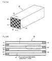
- FIG. 1 there is schematically illustrated in the form of a perspective view an example of the aggregate type honeycomb structure as a first embodiment of the present invention. It is generally indicated with a reference numeral 10.
- FIG. 2 (a) is a perspective view of an example of each of the honeycomb units forming together the honeycomb structure shown in FIG. 1, and
- FIG. 2(b) is a sectional view of the honeycomb unit in FIG. 2(a).
- the honeycomb unit is generally indicated with a reference numeral 20.
- the honeycomb unit 20 has a plurality of cells 21 (through-hole) formed extending from this side to that side. These cells 21 are laid side by wide each being separated from the other by a cell wall 23 to form together a honeycomb structure.
- the honeycomb structure may be closed at opposite ends of the cells 21 with a plug 22 to have checkered-pattern ends as necessary, for example, for the purpose of removing particulates in the exhaust gas from a diesel engine or the like.
- honeycomb block 15 A bundle of the plurality of honeycomb units 20 combined longitudinally side by side and joined to each other with a sealant layer 11 laid between adjacent ones is referred to herein as the "honeycomb block" 15.
- a sealant layer (will be referred to as “coating layer” hereunder) 12 to reinforce the honeycomb block and prevent exhaust gas from leaking.
- the honeycomb units 20 are assembled together to form the honeycomb block 15, and the coating layer 12 is provided over the surface of the honeycomb block 15 to form the aggregate type honeycomb structure. Even if the individual honeycomb units 20 are low in mechanical strength, thermal shock resistance, etc., the existence of the sealant layer 11 and coating layer 12 improves the thermal shock resistance and vibration resistance of the aggregate type honeycomb structure as a whole.
- the aggregate type honeycomb structure is high in thermal shock resistance and vibration resistance as above. It is inferred that even if a temperature distribution is caused to arise by an abrupt change in temperature or the like, the existence of the sealant layer 11 and coating layer 12 minimizes the difference in temperature between the honeycomb units 20 and the layers 11 and 12 absorb the thermal shock and vibration. Also, even if a crack has arisen in the honeycomb unit 20 due to a thermal stress or the like, the sealant layer 11 and coating layer 12 effectively block the crack from spreading over the entire honeycomb structure. Further, the outermost sealant layer, that is, the coating layer 12, plays a roll of aprotective frame for the honeycomb structure and is effective to maintain the shape of the honeycomb structure for a long term, namely, to improve the durability of the honeycomb structure.
- the honeycomb unit 20 should preferably be formed for easy joining between each other.
- the section of the honeycomb unit 20, perpendicular to the length of the cells (will be referred to as "unit section" hereunder) should desirably be square, rectangular or hexagonal.
- the unit section may be fan-shaped.
- the honeycomb unit 20 should preferably have a sectional area of 5 to 50 cm 2 . If the area of the unit section is smaller than 5 cm 2 , the pressure loss will be large. On the other hand, if the sectional area is larger than 50 cm 2 , a thermal stress developed in the honeycomb structure cannot be dispersed and the honeycomb structure is likely to crack when it is applied with the thermal stress. To have a marked operations and effects, the area of the unit section should more preferably be on the order of 6 to 40 cm 2 or 8 to 30 cm 2 .
- the honeycomb block formed from an assembly of a plurality of the honeycomb units 20 that is substantially the honeycomb structure should preferably be formed, for example, pillar-shaped, square-pillar shaped or elliptic pillar shaped one.
- the base material (skeletal component) of the honeycomb unit may be inorganic particles, fibers or whiskers of any one selected from among, for example, nitride ceramics such as aluminum nitride, silicon nitride, boron nitride, titanium nitride, etc., carbide ceramics such as silicon carbide, zirconium carbide, titanium carbide, tantalum carbide, tungsten carbide, etc. and oxide ceramics such as alumina, zirconia, cordierite, mullite, etc. Among these materials, the silicon carbide ceramics excellent in thermal resistance and mechanical properties and high in thermal conductivity is preferably usable.
- nitride ceramics such as aluminum nitride, silicon nitride, boron nitride, titanium nitride, etc.
- carbide ceramics such as silicon carbide, zirconium carbide, titanium carbide, tantalum carbide, tungsten carbide, etc.
- oxide ceramics such as
- the silicon carbide ceramic includes a ceramic formed from only silicon carbide as well as a ceramic in which silicon carbide is bonded by a metal, crystalloid or amorphous compound.
- the material of the honeycomb unit may contain a sub component (material). That is, the honeycomb unit may be a "hybrid type honeycomb unit".
- the hybrid type honeycomb unit should preferably contain at least inorganic ceramic particles and inorganic binder as base material and also a heterogeneous inorganic material (reinforcing material) as sub material. Since the inorganic ceramic particles can be bound together by the inorganic binder, such a honeycomb unit can be strong enough to stably maintain the honeycomb shape.
- the main and sub materials are different in components from each other, or they are identical in components to each other but different in shape from each other (for example, in particle size, aspect ratio, etc.) and physicality (for example, in crystal form, melting temperature, etc.).
- the hybridization of the honeycomb unit effectively contributes to an improved strength of the honeycomb structure.
- the inorganic material as sub material may be ceramic particles of one or more than one selected from among, for example, silicon carbide, siliconnitride, alumina, silica, zirconia, titania, ceria, zeolite and mullite.
- an inorganic fiber as the sub material may be fibers of one or more than one selected from among, for example, alumina fiber, silica fiber, silicon carbide fiber, silica alumina fiber, glass fiber, potassium titanate fiber and aluminum borate fiber.
- whiskers as the sub material if applicable, may be whiskers of one or more than one selected from among, for example, alumina, silica, zirconia, titania, ceria, zeolite and mullite.
- the hybrid type honeycomb unit is produced using the inorganic binder for the latter is considered to effectively assure a sufficient strength of the honeycomb unit even if baking is made at a low temperature.
- the inorganic binder may be, for example, inorganic sol, clay binder or the like.
- an inorganic sol of one or more than one selected from among, for example, alumina, silica, titania and water glass may be used as the inorganic binder.
- one or more than one selected from among, for example, clay, china clay, montmorillonite, double-chain structure clay (sepiolite and attapulgite), etc. may be used as the clay binder.
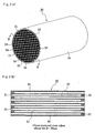
- FIG. 3 (a) there is schematically illustrated in the form of a perspective view an example of the integral type honeycomb structure (honeycomb monolith) as a second embodiment of the present invention.
- FIG. 3 (b) is a sectional view taken along the line B-B in FIG. 3(a).
- the integral type honeycomb structure generally indicated with a reference numeral 30, is a single cylindrical honeycomb monolith formed by assembling together a plurality of cells (through-holes) 31 longitudinally side by side with cell walls 33 laid between adjacent cells.
- Such integral type honeycomb structure is similar in configuration to the aggregate type honeycomb structure except the single honeycomb monolith is manufactured by sintering.
- the integral type honeycomb structure 30 has formed on the outer surface of the honeycomb monolith a sealant layer (also called "coating layer) 34 provided to prevent exhaust gas from leaking and reinforce the honeycomb monolith.
- a sealant layer also called "coating layer” 34 provided to prevent exhaust gas from leaking and reinforce the honeycomb monolith.
- each of these honeycomb structures according to the present invention is usable as an exhaust gas purifying filter to remove particulates in the exhaust gas.
- the porosity of the honeycomb unit should preferably be on the order of 20 to 80 %, and more preferably on the order of 50 to 70 %. If the porosity of the honeycomb unit is less than 20%, the pressure loss of the filter is likely to be higher. On the other hand, of the porosity exceeds 80%, the honeycomb structure will have a decreased strength and thus will possibly be broken easily. It should be noted that in case a catalyst is added to the cell walls and the latter are used as a catalyst carrier, the pressure loss in the honeycomb structure will easily be higher.
- the porosity of the cell walls should desirably be on the order of 50 to 70 %. Also note that the porosity is measured by a conventional well-known method such as the mercury injection method, Archimedes method and SEM (scanning electron microscope).
- the mean pore diameter of the honeycomb unit should preferably formed from a ceramic material of about 5 to 100 ⁇ m in mean pore diameter. If the mean pore diameter is less than 5 ⁇ m, the pressure loss of the filter against the exhaust gas will be higher. On the other hand, if the mean pore diameter is more than 100 ⁇ m, the particulates in the exhaust gas will pass through the pores more easily and thus be trapped less effectively.
- the kind of a material used to form the sealant layer is selected based on a predetermined pyschometric lightness (L*) ( ⁇ 60) as mentioned above.
- the material may be, for example, a mixture of oxide ceramic particles and inorganic binder, whose pyschometric lightness (L*) should desirably be small, a mixture of oxide ceramic particles, inorganic fiber and inorganic binder, whose pyschometric lightness (L*) is small, a mixture of oxide ceramic particles, inorganic particles and inorganic binder, whose pyschometric lightness (L*) is small, a mixture of oxide particles, inorganic fiber, inorganic particles and inorganic binder, whose pyschometric lightness (L*) is small, or any one of these mixtures to which an organic binder is added. Any one of these materials whose pyschometric lightness (L*) is less than 60 may be used as the sealant layer.
- the oxide ceramic particles may be fibers or whiskers of any one selected from among, for example, alumina, silica, titania, zirconia, cordierite, mullite and the like. Each of these materials may be used singly or more than one of them be used in combination.
- the above inorganic binders include, for example, silica sol, alumina sol and the like. Each of them may be used singly or more than one of them be used in combination. Among these inorganic binders, silica sol should desirably be used.
- the above inorganic fibers include, for example, ceramic fibers of silica-alumina, mullite, alumina, silica and the like. Each of them may be used singly or more than one of them be used in combination. Among these inorganic fibers, the ceramic fiber of silica-alumina should desirably be used.
- the inorganic particles used should basically be of less than 60 in pyschometric lightness (L*) .
- L* pyschometric lightness
- ceramic of carbide, nitride or the like may be used.
- an inorganic powder or whisker of silicon nitride, boron nitride or the like should preferably be used.
- organic binder there may be used any one or more than one selected from among, for example, polyvinyl alcohol, methyl cellulose, ethyl cellulose, carboxymethyl cellulose, etc.
- FIG. 4 shows an example of the on-vehicle exhaust gas purifying apparatus in which the honeycomb structure according to the present invention is used as an exhaust gas purifying filter.
- the exhaust gas purifying apparatus generally indicated with a reference numeral 40, includes an exhaust gas purifying filter F formed from the honeycomb structure, a casing 38 to cover the outer surface of the exhaust gas purifying filter F, a hermetic sealing member 35 to be interposed between the exhaust gas purifying filter F and casing 38, and a heating means (not shown) provided at an exhaust gas inlet as necessary.
- An inlet pipe 36 connected to an engine such as an internal combustion engine is connected to an end of the casing 38 where exhaust gas is introduced, and an exhaust pipe 37 connected to outside is connected to the other end of the casing 38.
- Exhaust gas coming from the internal combustion engine is passed through the inlet pipe 36, introduced into the exhaust gas purifying apparatus 40, and flows into the exhaust gas purifying filter F through cells open at their inlet ends (outlet ends are sealed with a sealant 22) .
- the exhaust gas passes through cell walls 23, particulates in the exhaust gas are captured by the cell walls 23.
- the exhaust gas is purified, then discharged through cells open at their outlet ends to outside the exhaust gas purifying filter F, and exhausted to outside through the exhaust pipe 37. It should be noted that in case gas component, not particulate, is to be purified by the exhaust gas purifying apparatus 40, the sealant 22 is unnecessary.
- the particulates will be massively deposited on the cell walls 23 of the exhaust gas purifying filter F, and when the pressure loss becomes large, the filter F is to be regenerated.
- the exhaust gas heated by a heating means such as catalyst, heater and the like provided as necessary is made to flow back into the cells 21 of the exhaust gas purifying filter F to heat the latter and the particulates deposited on the cell walls 23 are removed by burning.
- a material paste containing mainly he aforementioned material (one kind for a normal honeycomb unit while an inorganic material as the base material, inorganic material as the sub material , inorganic binder, etc. for a hybrid type honeycomb unit) is prepared, and the paste is extrusion-molded to prepare a green molding of a honeycomb unit.
- an organic binder, dispersant and molding additive in addition to the above.
- the organic binder may be one or more than one selected from among, for example, methyl cellulose, carboxymethyl cellulose, hydroxyethyl cellulose, polyethylene glycol, phenol resin and epoxy resin.
- the proportion of this organic binder should preferably be 1 to 10 % by mass in relation to 100 % by mass in total of the inorganic material of the first type, inorganic material of the second type and inorganic binder.
- the dispersant may be, for example, water, organic solvent (such as benzene or the like) or alcohol (such as methanol or the like).
- the molding additive may be, for example, ethylene glycol, dextrine, fatty acid, fatty acid soap or polyalcohol.
- the material paste should preferably be kneaded sufficiently by a mixer, attritor, kneader or the like, for example.
- the material paste should preferably be extrusion-molded to form the cells and cell walls.
- the green molding is dried by a microwave dryer, hot-air dryer, dielectric dryer, reduced-pressure dryer, vacuum dryer or freeze-dryer. Then, the cells are closed at one of their opposite ends with a plug and the molding is dried.
- the green molding is degreased.
- the degreasing conditions are to be adjusted according to the type and volume of the organic material in the green molding.
- the degreasing should preferably be done at about 400°C for about 2 hours.
- the green molding thus dried and degreased is baked.
- the baking should preferably be done at a temperature of about 600 to 2200 °C, for example.
- a green molding of oxide ceramic should preferably be baked in an inactive-gas atmosphere at about 600 to 1200 °C.
- the sealant paste prepared from the aforementioned materials is applied to the outer surface of the honeycomb unit thus prepared to provisionally join a plurality of such honeycomb units (16 pieces in the embodiment shown in FIG. 1) together.
- honeycomb units thus provisionally joined together are stably joined to each other by drying to provide a honeycomb block (honeycomb structure) having predetermined dimensions.
- the honeycomb block is an assembly of the honeycomb units.
- the drying temperature for stabilizing the honeycomb units joined together should normally be within a range of about 100 to 200 °C, which temperature varies a little depending upon the type and volume of the organic material in the green molding.
- the sealant layer 11 provided between the adjacent honeycomb units may be compact but it may also be porous to permit the exhaust gas to flow through.
- at least the coating layer 12 as the outermost layer should desirably be a compact layer for the reason that when the aggregate type honeycomb structure according to the present invention is installed in an exhaust gas passage of an internal combustion engine, the coating layer 12 has to prevent the exhaust gas from leaking out from the outer surface of the honeycomb block.
- the sealant layer 11 used to join the honeycomb units together should preferably be on the order of 0.3 to 3 mm in thickness. If the thickness of the sealant layer 11 is less than 0.3 mm, it is not possible to assure any sufficient adhesion strength. On the other hand, a thickness of more than 3 mm will possibly lead to a larger pressure loss.
- a sealant may be applied to the outer surface, that is, lateral side face, of the honeycomb structure and stabilized by drying to form the sealant layer (coating layer) 12.
- the coating layer 12 should desirably be formed to protect the outer surface of the honeycomb units and reinforce the honeycomb units.
- the material of the sealant for the coating layer 12 is not limited to any special one, but it may be the same as, or different from that of the sealing layer 11.
- the coating layer should preferably be 0.1 to 3 mm thick. If the thickness is less than 0.1 mm, the outer surface of the honeycomb block cannot sufficiently be protected, which may possibly lead to gas leakage, and cannot be reinforced.
- a thickness of more than 3 mm will be apt to lead to cracking in the honeycomb structure when the latter is applied with a thermal stress as well as to a larger pressure loss.
- the coating layer may be dried and stabilized under almost the same conditions as those for the sealant layer.
- the assembly of honeycomb units is preliminarily baked.
- the assembly can be degreased in case the sealant and coating layers contain any organic binder.
- the preliminary baking is effected under conditions which should appropriately be determined according to the type and volume of an organic material, if any, in the honeycomb-unit assembly, but it should preferably be done at a temperature of about 400 to 800 °C for a time of about 1 to 2 hours.
- the honeycomb structure thus obtained yet carries a catalyst component, and so it may be used as a honeycomb catalyst.
- the catalyst component may be a noble metal, alkali metal compound, alkali earth metal compound, oxide or the like.
- the noble metal there may be used one or more than one selected from among, for example, platinum, palladium and rhodium.
- the alkali metal compound may be one or more than one selected from among, for example, potassium, sodium and the like.
- the alkali earth metal compound may be a compound of barium or the like, for example.
- the oxides for use as the catalyst component may be perovskite (La: 0.75, K: 0.25, MnO: 3, etc.), CeO 2 or the like.
- the honeycomb catalyst may be the so-called three-component catalyst or NO x occlusion catalyst for use in the on-vehicle exhaust gas purifying apparatus.
- the examples of the present invention were tested to evaluate the action and effect of the sealant layer (adhesive and coating material) formed on the outer surfaces of the silicon carbide based honeycomb units and sealant layer formed on the outer surfaces of the cordierite honeycomb monolith.
- the sealant layer the silicon carbide based honeycomb unit was different in coloring agent from that on the cordierite honeycomb monolith.
- the paste No. 1 was a heat-resistant sealant paste that is a mixture of 25% by mass of an inorganic powder ( ⁇ -alumina particles of 0.5 ⁇ m in mean size), 5% by mass of iron oxide, 10% by mass of inorganic fiber (silica-alumina fiber of 10 ⁇ m in mean diameter and 200 ⁇ m in mean length), 30% by mass of silica sol (30% by mass in concentration), 5% by mass of carboxymethyl cellulose and 25% by mass of water.
- Each of the above pastes was shaped to a diameter of 50 mm and thickness of 5 mm, solidified at 120°C, and then heat-treated at 600°C for 3 hours.
- the pyschometric lightness (L*) of each of the 13 types of samples was measured by a spectrocolorimeter (SPECTRO COLOR METER Model SQ2000 by the Nippon Denshoku). The results of measurement are also shown in Table 1.
- a honeycomb unit was formed a mixture of 80% by mass of a silicon carbide powder (particles of 8.5 ⁇ m in mean diameter) and 20% by mass of a silicon carbide powder (particles of 0.2 ⁇ m in mean diameter).
- the paste thus prepared was extrusion-molded by a mold designed for an intended honeycomb shape to provide a honeycomb molding having many through-holes (cells), and the honeycomb molding was closed at either of the opposite ends of the through-holes with a plug to have checkered- pattern ends.
- the honeycomb molding was dried at 150°C, degreased at 500°C and then baked in an inactive-gas atmosphere at 2200°C to form a honeycomb unit having dimensions of 34.3 x 34.3 x 150 mm.
- a honeycomb unit was formed a mixture of 80% by mass of a silicon carbide powder (particles of 8.5 ⁇ m in mean diameter) and 20% by mass of a metallic silicon powder (particles of 0.2 ⁇ m in mean diameter).
- methyl cellulose as molding additive 10 parts by mass of methyl cellulose as molding additive was added to the 100 parts by mass of the material powders and they were mixed together. Further, 18 parts by weight of a dispersant composed of an organic solvent and water were added to the mixture and all these materials were kneaded together. Finally, the paste thus prepared was molded by a mold designed for an intended honeycomb shape to provide a honeycomb molding having many through-holes (cells), and the honeycomb molding was closed at either of the opposite ends of the through-holes with a plug to have checkered-pattern ends. The honeycomb molding was dried at 150°C, degreased at 500°C and then baked in an inactive-gas atmosphere at 1400°C to form a honeycomb unit having dimensions of 34.3 x 34.3 x 150 mm.
- honeycomb unit 16 samples of the honeycomb unit were prepared, and those of them which were equivalent in level to each other are joined together with the aforementioned sealant paste Nos. 1 to 13.
- the assembly of the honeycomb-unit samples were dried at 150°C for 2 hours, and then based at 500°C. Thereafter, the assembly was cut at the periphery thereof using a diamond cutter to provide a cylindrical ceramic block.
- Cylindrical exhaust gas purifying honeycomb filters (of about 140 mm in diameter and 150 mm in length) were produced with the sealant layer and coating layer (outermost layer) being varied in thickness (A to D as shown in Tables 2 and 3) from one filter to another.
- talc powder 10 ⁇ m in mean particle size
- 10 parts by mass of china clay 9 ⁇ m in mean particle size
- 17 parts by mass of alumina powder 9 ⁇ m in mean particle size
- 16 parts by mass of aluminum hydroxide powder 5 ⁇ m in mean particle size
- 15 parts by mass of silica powder 10 ⁇ m in mean particle size
- 10 parts by mass of acrylic powder 40 ⁇ m in mean particle size
- 5 parts by mass of methyl cellulose and 18 parts by mass of a dispersant composed of organic solvent and water were kneaded together.
- the mixture thus kneaded was molded by a mold designed for an intended honeycomb shape to provide a honeycomb molding having many through-holes, and the honeycomb molding was closed at either of the opposite ends of the through-holes with a plug to have checkered-pattern ends.
- the molding was dried at 140°C, degreased at 400°C, and baked in the atmospheric air at 1400°C to form an integral type honeycomb monolith of 143.8 mm in diameter and 150 mm in length.
- the pyschometric lightness (L*) on the surface of the sample was measured as in the pyschometric-lightness measurement of the sealant-paste samples and the result of measurement was 58.67 (also shown in Table 4).
- Cylindrical exhaust gas purifying filters were produced with the coating layer (outermost layer) being varied in thickness (A to D as shown in Tables 4) from one filter to another.
- Table 2 (°C) Paste Pyschometric lightness A B C D Sealant layer thickness Coating layer thickness Sealant layer thickness Coating layer thickness Sealant layer thickness Coating layer thickness Sealant layer thickness Coating layer thickness L* 0.3mm 0.3mm 0.5mm 0.5mm 1.0mm 1.0mm 3.0mm 3.0mm 1 86.00 450 455 460 470 2 75.93 460 465 470 480 3 65.76 470 475 480 490 4 55.58 520 525 530 540 5 45.41 530 535 540 550 6 87.28 443 448 453 463 7 78.60 453 458 463 473 8 69.93 465 470 475 485 9 61.26 466 471 476 486 10 52.58 530 535 540 550 11 43.91 540 545 550
- Each of the honeycomb structures A to D shown in Tables 2 to 4 was disposed in the exhaust gas passage of an exhaust gas purifying apparatus provided for a diesel engine of 2000 cc displacement as shown in FIG. 4, and the engine was driven at 3000 rpm and 50 Nm.
- a thermocouple A was installed just before a filter inside an exhaust pipe 37 while a thermocouple B was in a position 10 cm just after that filter to measure the temperature.
- the exhaust gas was stably at a temperature of 430°C at the filter inlet (measuring point A) in about 10 minutes after the engine was put into run, the exhaust gas temperature was measured at the filter outlet (measuring point B).
- Table 2 such a relation in the Si-SiC aggregate type filter is shown in Table 3
- such a relation in the cordierite integral type filter is shown in Table 4.
- the filter outlet temperatures were higher by 90°C or more than those in the filters not colored.
- the honeycomb structure according to the present invention is used as an exhaust gas purifying apparatus or filter for purifying exhaust gas discharged from an internal combustion engine, boiler, heating furnace, gas turbine or various industrial processes. It is usable as a diesel particulate filter (DPF) having an on-vehicle exhaust gas purifying catalyst carrier or having a function to filtrate and remove, by combustion, particulate matters in exhaust gas.
- DPF diesel particulate filter
- it is utilizable for any other application (adsorption of gas and liquid components, for example) without carrying any catalyst component or for a similar application.
Landscapes
- Chemical & Material Sciences (AREA)
- Engineering & Computer Science (AREA)
- Ceramic Engineering (AREA)
- Materials Engineering (AREA)
- Organic Chemistry (AREA)
- Structural Engineering (AREA)
- Chemical Kinetics & Catalysis (AREA)
- Inorganic Chemistry (AREA)
- Combustion & Propulsion (AREA)
- Health & Medical Sciences (AREA)
- General Chemical & Material Sciences (AREA)
- General Engineering & Computer Science (AREA)
- Environmental & Geological Engineering (AREA)
- Oil, Petroleum & Natural Gas (AREA)
- Biomedical Technology (AREA)
- Toxicology (AREA)
- Mechanical Engineering (AREA)
- Analytical Chemistry (AREA)
- Catalysts (AREA)
- Exhaust Gas Treatment By Means Of Catalyst (AREA)
- Filtering Materials (AREA)
- Exhaust Gas After Treatment (AREA)
- Laminated Bodies (AREA)
- Filtering Of Dispersed Particles In Gases (AREA)
- Ceramic Products (AREA)
Abstract
Description
- The present invention generally relates to a honeycomb structure, and more particularly to a ceramic honeycomb structure suitably usable in an apparatus for purification of exhaust gas from an internal engine used on an automobile.
- The honeycomb structures used in the exhaust gas purification apparatuses for the automotive internal engines include a monolith type one, an aggregate type one formed a plurality of honeycomb units joined together with a sealant, and the like.
- Many of the aggregate type honeycomb structures use the sealant (adhesive) to integrally assemble the honeycomb units together. As the sealant, there is used a mixture of, for example, ceramic particles of carbide, nitride or the like, which is high in thermal conductivity for an increased regeneration efficiency, and an inorganic binder as an additive (as in the
Japanese Unexamined Patent Publication No. 28246/1996 - The honeycomb structure disclosed in the above
Japanese Unexamined Patent Publication No. 28246/1996 - On the other hand, ceramic particles of a white oxide low in heat conductance, such as alumina, silica or the like, in the sealant will be a thermal barrier to the honeycomb structure. In this respect, the use of such ceramic particles will solve the above-mentioned problem. However, the use of the ceramic particles cannot solve the above problem of the low heating-up performance even if the sealant layer is formed thick.
- The present invention has an object to overcome the above-mentioned drawbacks of the prior art by providing a honeycomb structure having an improved heating-up performance with the performance of thermal conduction being limited a little.
- The present invention has another object to provide a honeycomb structure having an improved performance of exhaust gas purification.
- To attain the above objects, the inventors of the present invention made many researches and experiments and found that the problem of the conventional honeycomb structures could be solved firstly by using ceramic of white oxide relatively low in thermal conductance such as silica or alumina as the main component of the sealant and secondly by adding a coloring agent to the oxide ceramic to adjust the color of the sealant to a dark color low in brightness.
- The above object can be attained by providing an aggregate type honeycomb structure formed from a honeycomb block formed by assembling together honeycomb units each including a plurality of cells assembled together side by side longitudinally and cell walls isolating adjacent ones of the cells from each other by joining with a sealant layer laid between the honeycomb units, wherein the sealant layer containing oxide particles, inorganic binder and a coloring agent.
- Also the above object can be attained by providing an integral type honeycomb structure including a honeycomb monolith formed from a plurality of cells assembled together longitudinally side by side and cell walls isolating adjacent ones of the cells from each other, and a sealant layer provided on the outer surface of the honeycomb monolith, wherein the sealant layer containing oxide particles, inorganic binder and a coloring agent.
- Note that the present invention is advantageous in that:
- the honeycomb block has the outermost surface thereof surrounded with the sealant layer;
- the sealant layer has a color whose psychometric lightness (L*) specified in JIS Z 8729 (CIE (1976)) is 86.00 or less;
- the coloring agent comprises one or more selected from among inorganic metal compounds consisting of ion oxide, copper oxide, CoO·nAl2O3, Co3(PO4)2 and other cobalt compound;
- the oxide particle comprises any one of alumina, zirconia, titania and silica;
- the cells are closed at one of the opposite ends thereof with a plug;
- the honeycomb unit or honeycomb monolith carries a catalyst component; and
- the honeycomb structure is used as an on-vehicle exhaust gas purifying apparatus.
- In the above honeycomb structure according to the present invention, since the sealant layer provided between the honeycomb units or sealant layer (coating layer) on the outer surface of the honeycomb block or honeycomb monolith has the color thereof darkened due to the added coloring agent, the performance of the exhaust gas purification can be improved without deterioration of the heating-up performance. Also, since the sealant layer ceramic particles of a white oxide, the honeycomb structure will not have the temperature thereof easily lowered and can uniformly be heated appropriately. Thus, the honeycomb structure can considerably be improved in performance of purification.
-
- FIG. 1 is a perspective view of the aggregate type honeycomb structure according to the present invention.
- FIG. 2 (a) is a perspective view of the honeycomb unit used in the aggregate type honeycomb structure, and FIG. 2 (b) is a sectional view taken along the line A-A in Fig. 2(a).
- FIG. 3 (a) is a perspective view of the integral type honeycomb structure, and FIG. 3 (b) is a sectional view taken along the line B-B in Fig. 3 (a) .
- FIG. 4 is a sectional view of the on-vehicle exhaust gas purifying apparatus using the honeycomb structure according to the present invention.
- The inventors of the present invention made experiments on the honeycomb structure in which the honeycomb units are joined to each other with the sealant for heat resistance and durability with the heating-up performance and performance of exhaust gas purification being taken in consideration. They found from the results of the experiments that coloring of the sealant layer improved the warmth retaining property of a honeycomb structure-made filter. That is, the present invention is characterized in that the sealant (adhesive) made of ceramic particles of a white oxide is to be colored with a coloring agent. It was revealed from the experiment results that use of the colored sealant considerably improved the warmth retaining property of the honeycomb structure.
- The inventors inferred that in the honeycomb structure, the sealant layer, when colored as above, will have a color whose psychometric lightness (L*) is lower (darker color).
- Generally, the lightness as the reference of the brightness of a material will be higher as light incident upon an obj ect is reflected more. Also, three primary colors of a color material (in subtractive color mixing) can be represented by three colors: cyan (greenish blue), magenta (purplish red) and yellow. Since the cyan absorbs red (orange) whose wavelength is in the long-wave band (600 to 700 nm), it will emit greenish blue light. Since the magenta absorbs green (yellow) whose wavelength is in the medium-wave band (400 to 500 nm), it will emit purplish red light. Since the yellow absorbs blue (purple) whose wavelength is in the short-wave band (300 to 400 nm), it will emit yellow light.
- Since the colors absorb the light of their wavebands as above when they are mixed together, their reflection will absolutely be smaller. Therefore, a color like white will be easy to reflect. The above has been believed to be applicable to visible rays of light alone, but the Inventors found through their experiments that the above is also true for the rays of light in other wavebands such as ultraviolet ray.
- The inventors' findings revealed that even if the matrix component of the sealant layer is white, addition of a coloring agent to the matrix component to lower the brightness of the sealant layer will enable the outer surface and rear side (gas outlet) of a honeycomb structure to retain heat highly effectively.
- More particularly, the exhaust gas from an engine or the like is of a high temperature because the molecules themselves in the exhaust gas have high thermal energy. Generally, the exhaust gas molecules collide with the honeycomb structure (filter) used in the exhaust gas purifying apparatus, that contacts the exhaust gas, and the heat is conducted to the honeycomb structure which will thus reach a high temperature.
- The Inventors of the present invention inferred that the filter once heated as above radiates heat as an electromagnetic wave and, for inhibition of such heat radiation, it is effective to lower the filter brightness by coloring the filter. Lowering the filter brightness is also effective to inhibit generation of visible rays of light and other electromagnetic waves. Thus, the filter will have an improved effect of keeping warm and the catalytic activity and combustion efficiency for purification of the exhaust gas and removal of particulates will be improved.
- Note that CIE (1976) pyschometric lightness (L*) is a numerical value of a material specified in the JIS standard JIS Z 8105 (2000), and more specifically, it is a numerical value defined by the following values as in the standard JIS Z 8729 (2004):


where Y is a tristimulus value Y or Y10 in XYZ color system or X10Y10Z10 color system, respectively, and Yn is a value Y or Y10 defined by the standard illuminant and auxiliary standard illuminant of a perfect reflector. - Note that the XYZ color system or X10Y10Z10 color system is specified in the standard JIS Z 8701 (1999). More specifically, the pyschometric lightness (L*) can be determined by the spectrophotometric colorimetry and tristimulus value direct reading as specified in the standard JIZ Z 8722 (2000). The CIE (1976) pyschometric lightness (L*) is represented by any of the numerical values 0 to 100 and can be calculated down to two places of decimals. The greater the numerical value, the higher the brightness is. On the contrary, the smaller the numerical value, the lower the brightness is. It should be noted that the present invention is based on the method of numerical value calculation as specified in the above standards.
- The coloring agent used in the present invention contains a pigment and dye. The pigment is not soluble in water or the like. It includes organic and inorganic ones. An organic pigment of phthalocyanine, dioxazine or anthraquinone origin, more specifically, quinacridone, Watchung Red, dioxazine violet or the like, is suitably usable as the organic pigment. Also, as the inorganic pigment, there may be used an iron oxide (red iron oxide: Fe2O3), copper oxide, carbon, barium sulfate (BaSO4), vermilion (HgS), cadmium red (Cd(S, Se)), chrome yellow (PbCrO4), ultramarine (2Al2Na4Sl3O4), cobalt compound (cobalt blue: CoO·nAl2O3, cobalt purple:Co3(PO4)2 etc.) , zinc-chromate (K2O·4ZnO·4CrO3·3H2O, ZnCrO4·4Zn (OH)2) or the like.
- The dye should preferably be soluble in water and well adherent to inorganic particles (oxide particles). As the dye, there may be used, for example, an azo dye, anthraquinone dye, indigoid dye, sulfide dye, triphenyl methane dye, pyrazolone dye, stilbene dye, diphenyl methane dye, alizarin dye, acridine dye, quinonimine dye, azine dye, oxazine dye, thiazin dye, thiazole dye, methine dye, nitro dye, nitroso dye or the like.
- According to the present invention, a sealant containing white oxide ceramic particles may be used as the base and colored by adding a coloring agent to prepare the sealant layer having a desirable pyschometric lightness (L*), which is based on the Inventors inference which will be given below:
- The oxide ceramic particle includes gas bubbles, lattice defect, OH group, etc. which will scatter light. Thus, when the light impinges an oxide particle, it will be scattered to appear white. At this time, rays of light having wavelengths in various wavebands, for example, infrared rays, will be scattered (reflected). On the contrary, if the sealant layer is colored, light coming in the sealant layer is not apt to easily be scattered even when it impinges the oxide particle. That is, the coloring of the sealant layer will enable the oxide ceramic particles and coloring agent to efficiently absorb light energy, and thus the light energy can efficiently be converted into thermal energy.
- Namely, the darker the color of the material (sealant layer), the more easily the material can absorb electromagnetic energy (radiant heat) generated by combustion of a hot exhaust gas, especially, heat rays of large wavelength (visible rays of light in addition to infrared rays). Thus, the sealant layer will be improved in rate of heat transfer by radiation and hence in warmth retaining property. Therefore, the honeycomb structure will have an improved performance of exhaust gas purification.
- The present invention will be illustrated and explained in detail below concerning honeycomb structures of an aggregate type and integral type.
- The aggregate type honeycomb structure is the first embodiment of the present invention. It is formed from a honeycomb block formed by assembling a plurality of honeycomb units together in the form of a pillar with a sealant layer laid between adjacent honeycomb units. Each of the honeycomb units is a pillar-shaped honeycomb ceramic member formed from a plurality of cells (through-hole) assembled together longitudinally side by side with a cell wall laid between adjacent cells.
- On the other hand, the integral type honeycomb structure is the second embodiment of the present invention. It is formed as a single unit, namely, as a honeycomb monolith.
- Referring now to FIG. 1, there is schematically illustrated in the form of a perspective view an example of the aggregate type honeycomb structure as a first embodiment of the present invention. It is generally indicated with a
reference numeral 10. FIG. 2 (a) is a perspective view of an example of each of the honeycomb units forming together the honeycomb structure shown in FIG. 1, and FIG. 2(b) is a sectional view of the honeycomb unit in FIG. 2(a). The honeycomb unit is generally indicated with areference numeral 20. Thehoneycomb unit 20 has a plurality of cells 21 (through-hole) formed extending from this side to that side. Thesecells 21 are laid side by wide each being separated from the other by acell wall 23 to form together a honeycomb structure. Also, the honeycomb structure may be closed at opposite ends of thecells 21 with aplug 22 to have checkered-pattern ends as necessary, for example, for the purpose of removing particulates in the exhaust gas from a diesel engine or the like. - A bundle of the plurality of
honeycomb units 20 combined longitudinally side by side and joined to each other with asealant layer 11 laid between adjacent ones is referred to herein as the "honeycomb block" 15. Between the outermost surface of thehoneycomb block 15 and a stainless steel-made casing, there should desirably be provided a sealant layer (will be referred to as "coating layer" hereunder) 12 to reinforce the honeycomb block and prevent exhaust gas from leaking. Thehoneycomb units 20 are assembled together to form thehoneycomb block 15, and thecoating layer 12 is provided over the surface of thehoneycomb block 15 to form the aggregate type honeycomb structure. Even if theindividual honeycomb units 20 are low in mechanical strength, thermal shock resistance, etc., the existence of thesealant layer 11 andcoating layer 12 improves the thermal shock resistance and vibration resistance of the aggregate type honeycomb structure as a whole. - That is, the aggregate type honeycomb structure is high in thermal shock resistance and vibration resistance as above. It is inferred that even if a temperature distribution is caused to arise by an abrupt change in temperature or the like, the existence of the
sealant layer 11 andcoating layer 12 minimizes the difference in temperature between thehoneycomb units 20 and thelayers honeycomb unit 20 due to a thermal stress or the like, thesealant layer 11 andcoating layer 12 effectively block the crack from spreading over the entire honeycomb structure. Further, the outermost sealant layer, that is, thecoating layer 12, plays a roll of aprotective frame for the honeycomb structure and is effective to maintain the shape of the honeycomb structure for a long term, namely, to improve the durability of the honeycomb structure. - Note that the
honeycomb unit 20 should preferably be formed for easy joining between each other. For example, the section of thehoneycomb unit 20, perpendicular to the length of the cells (will be referred to as "unit section" hereunder) should desirably be square, rectangular or hexagonal. Also, the unit section may be fan-shaped. - Also, the
honeycomb unit 20 should preferably have a sectional area of 5 to 50 cm2. If the area of the unit section is smaller than 5 cm2, the pressure loss will be large. On the other hand, if the sectional area is larger than 50 cm2, a thermal stress developed in the honeycomb structure cannot be dispersed and the honeycomb structure is likely to crack when it is applied with the thermal stress. To have a marked operations and effects, the area of the unit section should more preferably be on the order of 6 to 40 cm2 or 8 to 30 cm2. - The honeycomb block formed from an assembly of a plurality of the
honeycomb units 20 that is substantially the honeycomb structure, should preferably be formed, for example, pillar-shaped, square-pillar shaped or elliptic pillar shaped one. - The base material (skeletal component) of the honeycomb unit may be inorganic particles, fibers or whiskers of any one selected from among, for example, nitride ceramics such as aluminum nitride, silicon nitride, boron nitride, titanium nitride, etc., carbide ceramics such as silicon carbide, zirconium carbide, titanium carbide, tantalum carbide, tungsten carbide, etc. and oxide ceramics such as alumina, zirconia, cordierite, mullite, etc. Among these materials, the silicon carbide ceramics excellent in thermal resistance and mechanical properties and high in thermal conductivity is preferably usable. Especially, ceramic containing metallic silicon, silicon- or silicate compound-bonded ceramic or the like may be suitably usable. It should be noted that the silicon carbide ceramic includes a ceramic formed from only silicon carbide as well as a ceramic in which silicon carbide is bonded by a metal, crystalloid or amorphous compound.
- In addition to the above-mentioned skeletal component (base material), the material of the honeycomb unit may contain a sub component (material). That is, the honeycomb unit may be a "hybrid type honeycomb unit".
- The hybrid type honeycomb unit should preferably contain at least inorganic ceramic particles and inorganic binder as base material and also a heterogeneous inorganic material (reinforcing material) as sub material. Since the inorganic ceramic particles can be bound together by the inorganic binder, such a honeycomb unit can be strong enough to stably maintain the honeycomb shape.
- Note here that in the hybridization of the inorganic materials as base material and sub material, respectively, the main and sub materials are different in components from each other, or they are identical in components to each other but different in shape from each other (for example, in particle size, aspect ratio, etc.) and physicality (for example, in crystal form, melting temperature, etc.). The hybridization of the honeycomb unit effectively contributes to an improved strength of the honeycomb structure.
- The inorganic material as sub material may be ceramic particles of one or more than one selected from among, for example, silicon carbide, siliconnitride, alumina, silica, zirconia, titania, ceria, zeolite and mullite. Also, an inorganic fiber as the sub material, if applicable, may be fibers of one or more than one selected from among, for example, alumina fiber, silica fiber, silicon carbide fiber, silica alumina fiber, glass fiber, potassium titanate fiber and aluminum borate fiber. Also, whiskers as the sub material, if applicable, may be whiskers of one or more than one selected from among, for example, alumina, silica, zirconia, titania, ceria, zeolite and mullite.
- The hybrid type honeycomb unit is produced using the inorganic binder for the latter is considered to effectively assure a sufficient strength of the honeycomb unit even if baking is made at a low temperature. The inorganic binder may be, for example, inorganic sol, clay binder or the like. For example, an inorganic sol of one or more than one selected from among, for example, alumina, silica, titania and water glass may be used as the inorganic binder. Also, one or more than one selected from among, for example, clay, china clay, montmorillonite, double-chain structure clay (sepiolite and attapulgite), etc. may be used as the clay binder.
- Referring here to FIG. 3 (a), there is schematically illustrated in the form of a perspective view an example of the integral type honeycomb structure (honeycomb monolith) as a second embodiment of the present invention. FIG. 3 (b) is a sectional view taken along the line B-B in FIG. 3(a). As shown, the integral type honeycomb structure, generally indicated with a
reference numeral 30, is a single cylindrical honeycomb monolith formed by assembling together a plurality of cells (through-holes) 31 longitudinally side by side withcell walls 33 laid between adjacent cells. Such integral type honeycomb structure is similar in configuration to the aggregate type honeycomb structure except the single honeycomb monolith is manufactured by sintering. - The integral
type honeycomb structure 30 has formed on the outer surface of the honeycomb monolith a sealant layer (also called "coating layer) 34 provided to prevent exhaust gas from leaking and reinforce the honeycomb monolith. - Each of these honeycomb structures according to the present invention is usable as an exhaust gas purifying filter to remove particulates in the exhaust gas. In this case, the porosity of the honeycomb unit should preferably be on the order of 20 to 80 %, and more preferably on the order of 50 to 70 %. If the porosity of the honeycomb unit is less than 20%, the pressure loss of the filter is likely to be higher. On the other hand, of the porosity exceeds 80%, the honeycomb structure will have a decreased strength and thus will possibly be broken easily. It should be noted that in case a catalyst is added to the cell walls and the latter are used as a catalyst carrier, the pressure loss in the honeycomb structure will easily be higher. On this account, the porosity of the cell walls should desirably be on the order of 50 to 70 %. Also note that the porosity is measured by a conventional well-known method such as the mercury injection method, Archimedes method and SEM (scanning electron microscope).
- In case each of these honeycomb structures is used as an exhaust gas purifying filter to purify exhaust gas by trapping particulates in the exhaust gas, the mean pore diameter of the honeycomb unit should preferably formed from a ceramic material of about 5 to 100 µm in mean pore diameter. If the mean pore diameter is less than 5 µm, the pressure loss of the filter against the exhaust gas will be higher. On the other hand, if the mean pore diameter is more than 100 µm, the particulates in the exhaust gas will pass through the pores more easily and thus be trapped less effectively.
- The kind of a material used to form the sealant layer is selected based on a predetermined pyschometric lightness (L*) (< 60) as mentioned above. The material may be, for example, a mixture of oxide ceramic particles and inorganic binder, whose pyschometric lightness (L*) should desirably be small, a mixture of oxide ceramic particles, inorganic fiber and inorganic binder, whose pyschometric lightness (L*) is small, a mixture of oxide ceramic particles, inorganic particles and inorganic binder, whose pyschometric lightness (L*) is small, a mixture of oxide particles, inorganic fiber, inorganic particles and inorganic binder, whose pyschometric lightness (L*) is small, or any one of these mixtures to which an organic binder is added. Any one of these materials whose pyschometric lightness (L*) is less than 60 may be used as the sealant layer.
- The oxide ceramic particles may be fibers or whiskers of any one selected from among, for example, alumina, silica, titania, zirconia, cordierite, mullite and the like. Each of these materials may be used singly or more than one of them be used in combination.
- The above inorganic binders include, for example, silica sol, alumina sol and the like. Each of them may be used singly or more than one of them be used in combination. Among these inorganic binders, silica sol should desirably be used.
- The above inorganic fibers include, for example, ceramic fibers of silica-alumina, mullite, alumina, silica and the like. Each of them may be used singly or more than one of them be used in combination. Among these inorganic fibers, the ceramic fiber of silica-alumina should desirably be used.
- Desirably, the inorganic particles used should basically be of less than 60 in pyschometric lightness (L*) . For example, ceramic of carbide, nitride or the like may be used. However, an inorganic powder or whisker of silicon nitride, boron nitride or the like should preferably be used.
- As the organic binder, there may be used any one or more than one selected from among, for example, polyvinyl alcohol, methyl cellulose, ethyl cellulose, carboxymethyl cellulose, etc.
- The above-mentioned honeycomb structure may be used as an exhaust gas purifying filter. FIG. 4 shows an example of the on-vehicle exhaust gas purifying apparatus in which the honeycomb structure according to the present invention is used as an exhaust gas purifying filter. As shown, the exhaust gas purifying apparatus, generally indicated with a
reference numeral 40, includes an exhaust gas purifying filter F formed from the honeycomb structure, acasing 38 to cover the outer surface of the exhaust gas purifying filter F, ahermetic sealing member 35 to be interposed between the exhaust gas purifying filter F and casing 38, and a heating means (not shown) provided at an exhaust gas inlet as necessary. Aninlet pipe 36 connected to an engine such as an internal combustion engine is connected to an end of thecasing 38 where exhaust gas is introduced, and anexhaust pipe 37 connected to outside is connected to the other end of thecasing 38. - Exhaust gas coming from the internal combustion engine is passed through the
inlet pipe 36, introduced into the exhaustgas purifying apparatus 40, and flows into the exhaust gas purifying filter F through cells open at their inlet ends (outlet ends are sealed with a sealant 22) . When the exhaust gas passes throughcell walls 23, particulates in the exhaust gas are captured by thecell walls 23. Thus, the exhaust gas is purified, then discharged through cells open at their outlet ends to outside the exhaust gas purifying filter F, and exhausted to outside through theexhaust pipe 37. It should be noted that in case gas component, not particulate, is to be purified by the exhaustgas purifying apparatus 40, thesealant 22 is unnecessary. - Also, in this exhaust
gas purifying apparatus 40, the particulates will be massively deposited on thecell walls 23 of the exhaust gas purifying filter F, and when the pressure loss becomes large, the filter F is to be regenerated. In this regeneration, the exhaust gas heated by a heating means such as catalyst, heater and the like provided as necessary is made to flow back into thecells 21 of the exhaust gas purifying filter F to heat the latter and the particulates deposited on thecell walls 23 are removed by burning. - Next, there will be explained an example of the method of producing the honeycomb structure according to the present invention:
- First, a material paste containing mainly he aforementioned material (one kind for a normal honeycomb unit while an inorganic material as the base material, inorganic material as the sub material , inorganic binder, etc. for a hybrid type honeycomb unit) is prepared, and the paste is extrusion-molded to prepare a green molding of a honeycomb unit. To the material paste, there may appropriately be added an organic binder, dispersant and molding additive in addition to the above. The organic binder may be one or more than one selected from among, for example, methyl cellulose, carboxymethyl cellulose, hydroxyethyl cellulose, polyethylene glycol, phenol resin and epoxy resin. The proportion of this organic binder should preferably be 1 to 10 % by mass in relation to 100 % by mass in total of the inorganic material of the first type, inorganic material of the second type and inorganic binder. The dispersant may be, for example, water, organic solvent (such as benzene or the like) or alcohol (such as methanol or the like). The molding additive may be, for example, ethylene glycol, dextrine, fatty acid, fatty acid soap or polyalcohol.
- The material paste should preferably be kneaded sufficiently by a mixer, attritor, kneader or the like, for example. The material paste should preferably be extrusion-molded to form the cells and cell walls.
- Next, the green molding is dried by a microwave dryer, hot-air dryer, dielectric dryer, reduced-pressure dryer, vacuum dryer or freeze-dryer. Then, the cells are closed at one of their opposite ends with a plug and the molding is dried.
- Next, the green molding is degreased. The degreasing conditions are to be adjusted according to the type and volume of the organic material in the green molding. For example, the degreasing should preferably be done at about 400°C for about 2 hours. Then, the green molding thus dried and degreased is baked. The baking should preferably be done at a temperature of about 600 to 2200 °C, for example. Especially, a green molding of oxide ceramic should preferably be baked in an inactive-gas atmosphere at about 600 to 1200 °C. With the above operations, there can be produced a honeycomb unit formed from a porous ceramic member having a honeycomb structure including a plurality of cells.
- Thereafter, on the surface of the honeycomb unit, there is formed an oxide film by heat treatment of the honeycomb unit thus baked in an acidized atmosphere at a temperature of 700°C or more or an oxide layer by coating an oxide ceramic as necessary.
- Next, the sealant paste prepared from the aforementioned materials is applied to the outer surface of the honeycomb unit thus prepared to provisionally join a plurality of such honeycomb units (16 pieces in the embodiment shown in FIG. 1) together.
- Then, the honeycomb units thus provisionally joined together are stably joined to each other by drying to provide a honeycomb block (honeycomb structure) having predetermined dimensions. Namely, the honeycomb block is an assembly of the honeycomb units. The drying temperature for stabilizing the honeycomb units joined together should normally be within a range of about 100 to 200 °C, which temperature varies a little depending upon the type and volume of the organic material in the green molding.
- Note that the
sealant layer 11 provided between the adjacent honeycomb units may be compact but it may also be porous to permit the exhaust gas to flow through. However, at least thecoating layer 12 as the outermost layer should desirably be a compact layer for the reason that when the aggregate type honeycomb structure according to the present invention is installed in an exhaust gas passage of an internal combustion engine, thecoating layer 12 has to prevent the exhaust gas from leaking out from the outer surface of the honeycomb block. - The
sealant layer 11 used to join the honeycomb units together should preferably be on the order of 0.3 to 3 mm in thickness. If the thickness of thesealant layer 11 is less than 0.3 mm, it is not possible to assure any sufficient adhesion strength. On the other hand, a thickness of more than 3 mm will possibly lead to a larger pressure loss. - A sealant may be applied to the outer surface, that is, lateral side face, of the honeycomb structure and stabilized by drying to form the sealant layer (coating layer) 12. The
coating layer 12 should desirably be formed to protect the outer surface of the honeycomb units and reinforce the honeycomb units. The material of the sealant for thecoating layer 12 is not limited to any special one, but it may be the same as, or different from that of thesealing layer 11. The coating layer should preferably be 0.1 to 3 mm thick. If the thickness is less than 0.1 mm, the outer surface of the honeycomb block cannot sufficiently be protected, which may possibly lead to gas leakage, and cannot be reinforced. On the other hand, a thickness of more than 3 mm will be apt to lead to cracking in the honeycomb structure when the latter is applied with a thermal stress as well as to a larger pressure loss. The coating layer may be dried and stabilized under almost the same conditions as those for the sealant layer. - After joining the honeycomb units together to each other with the sealant layer or forming the coating layer, the assembly of honeycomb units is preliminarily baked. With this preliminary baking, the assembly can be degreased in case the sealant and coating layers contain any organic binder. The preliminary baking is effected under conditions which should appropriately be determined according to the type and volume of an organic material, if any, in the honeycomb-unit assembly, but it should preferably be done at a temperature of about 400 to 800 °C for a time of about 1 to 2 hours. Even if the honeycomb structure thus subjected to the preliminarybaking is used at a high temperature, it will not discharge any exhaust gas contaminated by any burnt organic binder in the honeycomb structure for the organic binder has already been removed by burning at the time of the preliminary baking.
- Also, the honeycomb structure thus obtained yet carries a catalyst component, and so it may be used as a honeycomb catalyst. The catalyst component may be a noble metal, alkali metal compound, alkali earth metal compound, oxide or the like. As the noble metal, there may be used one or more than one selected from among, for example, platinum, palladium and rhodium. The alkali metal compound may be one or more than one selected from among, for example, potassium, sodium and the like. The alkali earth metal compound may be a compound of barium or the like, for example. The oxides for use as the catalyst component may be perovskite (La: 0.75, K: 0.25, MnO: 3, etc.), CeO2 or the like. The honeycomb catalyst may be the so-called three-component catalyst or NOx occlusion catalyst for use in the on-vehicle exhaust gas purifying apparatus.
- The examples of the present invention will be described in further detail, but the present invention is not limited to these examples.
- The examples of the present invention were tested to evaluate the action and effect of the sealant layer (adhesive and coating material) formed on the outer surfaces of the silicon carbide based honeycomb units and sealant layer formed on the outer surfaces of the cordierite honeycomb monolith. The sealant layer the silicon carbide based honeycomb unit was different in coloring agent from that on the cordierite honeycomb monolith.
- Thirteen types of sealant pastes were prepared. Each of the pastes was composed as shown in Table 1.
- The paste No. 1 was a heat-resistant sealant paste that is a mixture of 25% by mass of an inorganic powder (α-alumina particles of 0.5 µm in mean size), 5% by mass of iron oxide, 10% by mass of inorganic fiber (silica-alumina fiber of 10 µm in mean diameter and 200 µm in mean length), 30% by mass of silica sol (30% by mass in concentration), 5% by mass of carboxymethyl cellulose and 25% by mass of water.
- Similarly, other 12 types of pastes were prepared which were different in proportion of the material powder, inorganic fiber, silica sol and carboxymethyl cellulose from the paste No. 1 and each other as shown in Table 1.
- Each of the above pastes was shaped to a diameter of 50 mm and thickness of 5 mm, solidified at 120°C, and then heat-treated at 600°C for 3 hours. The pyschometric lightness (L*) of each of the 13 types of samples was measured by a spectrocolorimeter (SPECTRO COLOR METER Model SQ2000 by the Nippon Denshoku). The results of measurement are also shown in Table 1.

- Two types of aggregate type honeycomb structures were produced as will be described below:
- A honeycomb unit was formed a mixture of 80% by mass of a silicon carbide
powder (particles of 8.5 µm in mean diameter) and 20% by mass of a silicon
carbide powder (particles of 0.2 µm in mean diameter). - Next, 10 parts by mass of methyl cellulose as molding additive was added to the 100 parts by mass of the material powders and they were mixed together. Further, 18 parts by mass of a dispersant composed of an organic solvent and water were added to the mixture and all these materials were kneaded together. Finally, the paste thus prepared was extrusion-molded by a mold designed for an intended honeycomb shape to provide a honeycomb molding having many through-holes (cells), and the honeycomb molding was closed at either of the opposite ends of the through-holes with a plug to have checkered- pattern ends. The honeycomb molding was dried at 150°C, degreased at 500°C and then baked in an inactive-gas atmosphere at 2200°C to form a honeycomb unit having dimensions of 34.3 x 34.3 x 150 mm.
- Note that the pyschometric lightness (L*) on the surface of the honeycomb unit thus formed was measured as in the pyschometric-lightness measurement of the sealant-paste samples and the result of measurement was 40.23 (also shown in Table 2).
- A honeycomb unit was formed a mixture of 80% by mass of a silicon carbide powder (particles of 8.5 µm in mean diameter) and 20% by mass of a metallic silicon powder (particles of 0.2 µm in mean diameter).
- Next, 10 parts by mass of methyl cellulose as molding additive was added to the 100 parts by mass of the material powders and they were mixed together. Further, 18 parts by weight of a dispersant composed of an organic solvent and water were added to the mixture and all these materials were kneaded together. Finally, the paste thus prepared was molded by a mold designed for an intended honeycomb shape to provide a honeycomb molding having many through-holes (cells), and the honeycomb molding was closed at either of the opposite ends of the through-holes with a plug to have checkered-pattern ends. The honeycomb molding was dried at 150°C, degreased at 500°C and then baked in an inactive-gas atmosphere at 1400°C to form a honeycomb unit having dimensions of 34.3 x 34.3 x 150 mm.
- Note that the pyschometric lightness (L*) on the surface of the honeycomb unit thus formed was measured as in the pyschometric-lightness measurement of the sealant-paste samples and the pyschometric lightness (L*) measured was 44.67 (also shown in Table 3).
- Next, 16 samples of the honeycomb unit were prepared, and those of them which were equivalent in level to each other are joined together with the aforementioned sealant paste Nos. 1 to 13. The assembly of the honeycomb-unit samples were dried at 150°C for 2 hours, and then based at 500°C. Thereafter, the assembly was cut at the periphery thereof using a diamond cutter to provide a cylindrical ceramic block.
- Cylindrical exhaust gas purifying honeycomb filters (of about 140 mm in diameter and 150 mm in length) were produced with the sealant layer and coating layer (outermost layer) being varied in thickness (A to D as shown in Tables 2 and 3) from one filter to another.
- Forty parts by mass of a talc powder (10 µm in mean particle size), 10 parts by mass of china clay (9 µm in mean particle size), 17 parts by mass of alumina powder (9.5 µm in mean particle size), 16 parts by mass of aluminum hydroxide powder (5 µm in mean particle size), 15 parts by mass of silica powder (10 µm in mean particle size), 10 parts by mass of acrylic powder (40 µm in mean particle size), 5 parts by mass of methyl cellulose and 18 parts by mass of a dispersant composed of organic solvent and water were kneaded together.
- Next, the mixture thus kneaded was molded by a mold designed for an intended honeycomb shape to provide a honeycomb molding having many through-holes, and the honeycomb molding was closed at either of the opposite ends of the through-holes with a plug to have checkered-pattern ends. The molding was dried at 140°C, degreased at 400°C, and baked in the atmospheric air at 1400°C to form an integral type honeycomb monolith of 143.8 mm in diameter and 150 mm in length.
- After the cell walls were flattened, the pyschometric lightness (L*) on the surface of the sample was measured as in the pyschometric-lightness measurement of the sealant-paste samples and the result of measurement was 58.67 (also shown in Table 4).
- Cylindrical exhaust gas purifying filters were produced with the coating layer (outermost layer) being varied in thickness (A to D as shown in Tables 4) from one filter to another.
Table 2 (°C) Paste Pyschometric lightness A B C D Sealant layer thickness Coating layer thickness Sealant layer thickness Coating layer thickness Sealant layer thickness Coating layer thickness Sealant layer thickness Coating layer thickness L* 0.3mm 0.3mm 0.5mm 0.5mm 1.0mm 1.0mm 3.0mm 3.0mm 1 86.00 450 455 460 470 2 75.93 460 465 470 480 3 65.76 470 475 480 490 4 55.58 520 525 530 540 5 45.41 530 535 540 550 6 87.28 443 448 453 463 7 78.60 453 458 463 473 8 69.93 465 470 475 485 9 61.26 466 471 476 486 10 52.58 530 535 540 550 11 43.91 540 545 550 560 12 35.24 553 558 563 573 13 96.27 430 430 430 430 SiC filter 40.23 - - - - Table 3 (°C) Paste Pyschometric lightness A B C D Sealant layer thickness Coating layer thickness Sealant layer thickness Coating layer thickness Sealant layer thickness Coating layer thickness Sealant layer thickness Coating layer thickness L* 0.3mm 0.3mm 0.5mm 0.5mm 1.0mm 1.0mm 3.0mm 3.0mm 1 86.00 448 453 458 468 2 75.93 458 463 468 478 3 65.76 468 473 478 488 4 55.58 518 523 528 538 5 45.41 528 532 538 548 6 87.28 440 445 450 460 7 78.60 450 455 460 470 8 69.93 463 468 473 482 9 61.26 466 468 473 483 10 52.58 527 532 538 548 11 43.91 538 543 548 558 12 35.24 550 555 560 570 13 96.27 428 428 428 428 Si-SiC filter 44.67 - - - - Table 4 (°C) Paste Pyschometric lightness A B C D Coating layer thickness Coating layer thickness Coating layer thickness Coating layer thickness L* 0.3mm 0.5mm 1.0mm 3.0mm 1 86.00 450 455 460 470 2 75.93 460 465 470 480 3 65.76 470 475 480 490 4 55.58 520 525 530 540 5 45.41 530 535 540 550 6 87.28 443 448 453 463 7 78.60 453 458 463 473 8 69.93 465 470 475 485 9 61.26 466 471 476 486 10 52.58 530 535 540 550 11 43.91 540 545 550 560 12 35.24 553 558 563 573 13 96.27 440 440 440 440 Cordierite filter 58.67 - - - - - Each of the honeycomb structures A to D shown in Tables 2 to 4 was disposed in the exhaust gas passage of an exhaust gas purifying apparatus provided for a diesel engine of 2000 cc displacement as shown in FIG. 4, and the engine was driven at 3000 rpm and 50 Nm. A thermocouple A was installed just before a filter inside an
exhaust pipe 37 while a thermocouple B was in aposition 10 cm just after that filter to measure the temperature. When the exhaust gas was stably at a temperature of 430°C at the filter inlet (measuring point A) in about 10 minutes after the engine was put into run, the exhaust gas temperature was measured at the filter outlet (measuring point B). The relation between the temperatures and pastes in the SiC aggregate type filter is shown in Table 2, such a relation in the Si-SiC aggregate type filter is shown in Table 3, and such a relation in the cordierite integral type filter is shown in Table 4. - As will be seen from Tables 2 to 4, in case the sealant layers formed in each filter were 0.3 mm or more and they were colored to reduce the pyschometric lightness (L*), the filters had a higher temperature. For example, in a sample A in which the sealant layer was of the paste No. 1 of 86.00 in L* and 0.3 mm thick in the SiC aggregate type filter shown in Table 2, the temperature at the filter outlet was 450°C. In a sample D in which the sealant layer was of the paste No. 1 and 3.0 mm thick, the temperature at the filter outlet was 470°C. These test results are almost the same as the filter outlet temperatures of 443°C and 463°C in the samples A and B in which the sealant layer was of the paste No. 6 of 87.28 in L*. However, When the paste No. 12 very dark in color (L* = 35.24) was used, the filter outlet temperatures at the measuring points A and B were 553°C and 573°C, respectively. That is, the filter outlet temperatures were higher, which reveals that the filters have an improved effect of heat retention.
- More specifically, when the pyschometric lightness (L*) was 86. 0 or less, and more preferably, 60.00 or less (as in the paste Nos. 4, 5 and 10 to 12), the filter outlet temperatures were higher by 90°C or more than those in the filters not colored.
- As having been described in the foregoing, the honeycomb structure according to the present invention is used as an exhaust gas purifying apparatus or filter for purifying exhaust gas discharged from an internal combustion engine, boiler, heating furnace, gas turbine or various industrial processes. It is usable as a diesel particulate filter (DPF) having an on-vehicle exhaust gas purifying catalyst carrier or having a function to filtrate and remove, by combustion, particulate matters in exhaust gas. Of course, it is utilizable for any other application (adsorption of gas and liquid components, for example) without carrying any catalyst component or for a similar application.
Claims (15)
- An aggregate type honeycomb structure formed f rom a honeycomb block formed by assembling together honeycomb units each including a plurality of cells assembled together side by side longitudinally and cell walls isolating adjacent ones of the cells from each other by joining with a sealant layer laid between the honeycomb units, wherein the sealant layer containing oxide particles, inorganic binder and a coloring agent.
- The honeycomb structure according to claim 1, wherein the honeycomb block has the outermost surface thereof surrounded with the sealant layer.
- The honeycomb structure according to claim 1 or 2, wherein the sealant layer has a color whose psychometric lightness (L*) specified in JIS Z 8729 (CIE (1976)) is 86.00 or less.
- The honeycomb structure according to any one of claims 1 to 3, wherein the coloring agent comprises one or more selected from among inorganic metal compounds consisting of ion oxide, copper oxide, CoO·nAl2O3, Co3(PO4)2 and other cobalt compound.
- The honeycomb structure according to any one of claims 1 to 4, wherein the oxide particle comprises any one of alumina, zirconia, titania and silica.
- The honeycomb structure according to any one of claims 1 to 5, wherein the cells are closed at one of the opposite ends thereof with a plug.
- The honeycomb structure according to any one of claims 1 to 6, wherein the honeycomb unit carries a catalyst component.
- The honeycomb structure according to any one of claims 1 to 7, usable as an on-vehicle exhaust gas purifying apparatus.
- An integral type honeycomb structure including a honeycomb monolith formed from a plurality of cells assembled together longitudinally side by side and cell walls isolating adjacent ones of the cells from each other, and a sealant layer provided on the outer surface of the honeycomb monolith, wherein the sealant layer containing oxide particles, inorganic binder and a coloring agent.
- The honeycomb structure according to claim 9, wherein the sealant layer has a color whose psychometric lightness (L*) specified in JIS Z 8729 (CIE (1976)) is 86.00 or less.
- The honeycomb structure according to claim 9 or 10, wherein the coloring agent comprises one or more selected from among inorganic metal compounds consisting of ion oxide, copper oxide, CoO·nAl2O3, Co3(PO4)2 and other cobalt compound.
- The honeycomb structure according to any one of claims 9 to 11, wherein the oxide particle comprises any one of alumina, zirconia, titania and silica.
- The honeycomb structure according to any one of claims 9 to 12, wherein the cells are closed at one of the opposite ends thereof with a plug.
- The honeycomb structure according to any one of claims 9 to 13, wherein the honeycomb monolith carries a catalyst component.
- The honeycomb structure according to any one of claims 9 to 14, usable as an on-vehicle exhaust gas purifying apparatus.
Applications Claiming Priority (1)
| Application Number | Priority Date | Filing Date | Title |
|---|---|---|---|
| JP2005110712 | 2005-04-07 |
Publications (2)
| Publication Number | Publication Date |
|---|---|
| EP1710220A1 true EP1710220A1 (en) | 2006-10-11 |
| EP1710220B1 EP1710220B1 (en) | 2010-05-05 |
Family
ID=36609875
Family Applications (1)
| Application Number | Title | Priority Date | Filing Date |
|---|---|---|---|
| EP06290561A Expired - Lifetime EP1710220B1 (en) | 2005-04-07 | 2006-04-06 | Honeycomb structure |
Country Status (8)
| Country | Link |
|---|---|
| US (1) | US7641956B2 (en) |
| EP (1) | EP1710220B1 (en) |
| JP (1) | JP4805823B2 (en) |
| KR (1) | KR100822246B1 (en) |
| CN (1) | CN1926313B (en) |
| AT (1) | ATE466822T1 (en) |
| DE (1) | DE602006014045D1 (en) |
| WO (1) | WO2006112061A1 (en) |
Families Citing this family (108)
| Publication number | Priority date | Publication date | Assignee | Title |
|---|---|---|---|---|
| DE20023986U1 (en) | 1999-09-29 | 2008-09-18 | IBIDEN CO., LTD., Ogaki-shi | Ceramic filter arrangement |
| CN100427730C (en) * | 2002-02-05 | 2008-10-22 | 揖斐电株式会社 | Honeycomb filter for exhaust gas purification, adhesive, coating material, and method for producing honeycomb filter for exhaust gas purification |
| WO2003067042A1 (en) * | 2002-02-05 | 2003-08-14 | Ibiden Co., Ltd. | Honeycomb filter for exhaust gas decontamination |
| ATE385281T1 (en) * | 2002-03-04 | 2008-02-15 | Ibiden Co Ltd | HONEYCOMB FILTER FOR EXHAUST GAS PURIFICATION AND EXHAUST GAS PURIFICATION DEVICE |
| DE60317174T3 (en) * | 2002-03-22 | 2013-01-17 | Ibiden Co., Ltd. | METHOD OF PREPARING A WAVE FILTER FOR CLEANING EXHAUST GAS |
| WO2003093657A1 (en) * | 2002-04-10 | 2003-11-13 | Ibiden Co., Ltd. | Honeycomb filter for clarifying exhaust gas |
| WO2003093658A1 (en) * | 2002-04-11 | 2003-11-13 | Ibiden Co., Ltd. | Honeycomb filter for clarifying exhaust gas |
| CN1326593C (en) | 2003-02-28 | 2007-07-18 | 揖斐电株式会社 | Ceramic honeycomb structure |
| JP4932256B2 (en) * | 2003-09-12 | 2012-05-16 | イビデン株式会社 | Ceramic sintered body and ceramic filter |
| US7981475B2 (en) * | 2003-11-05 | 2011-07-19 | Ibiden Co., Ltd. | Manufacturing method of honeycomb structural body, and sealing material |
| ATE431321T1 (en) * | 2003-11-12 | 2009-05-15 | Ibiden Co Ltd | METHOD FOR PRODUCING THE CERAMIC STRUCTURE |
| US7387829B2 (en) * | 2004-01-13 | 2008-06-17 | Ibiden Co., Ltd. | Honeycomb structure, porous body, pore forming material for the porous body, and methods for manufacturing the pore forming material, the porous body and the honeycomb structure |
| KR100637298B1 (en) * | 2004-04-05 | 2006-10-24 | 이비덴 가부시키가이샤 | Honeycomb structural body, manufacturing method of the honeycomb structural body, and exhaust gas purifying device |
| KR100804933B1 (en) * | 2004-05-06 | 2008-02-20 | 이비덴 가부시키가이샤 | Honeycomb structure and method of manufacturing the same |
| WO2005110578A1 (en) * | 2004-05-18 | 2005-11-24 | Ibiden Co., Ltd. | Honeycomb structure and exhaust gas clarifying device |
| EP1647790B1 (en) * | 2004-07-01 | 2008-08-20 | Ibiden Co., Ltd. | Method of manufacturing porous ceramic body |
| JPWO2006013651A1 (en) * | 2004-08-04 | 2008-05-01 | イビデン株式会社 | Firing furnace and method for producing porous ceramic member using the same |
| EP1795262B1 (en) | 2004-09-30 | 2010-01-27 | Ibiden Co., Ltd. | Honeycomb structure |
| WO2006035823A1 (en) * | 2004-09-30 | 2006-04-06 | Ibiden Co., Ltd. | Honeycomb structure |
| EP1808217B1 (en) * | 2004-10-12 | 2009-07-22 | Ibiden Co., Ltd. | Ceramic honeycomb structure |
| EP1818098A4 (en) * | 2004-11-26 | 2008-02-06 | Ibiden Co Ltd | HONEYCOMB STRUCTURE |
| JP4870657B2 (en) * | 2005-02-04 | 2012-02-08 | イビデン株式会社 | Ceramic honeycomb structure and manufacturing method thereof |
| WO2006082940A1 (en) * | 2005-02-04 | 2006-08-10 | Ibiden Co., Ltd. | Ceramic honeycomb structure |
| JP2006223983A (en) * | 2005-02-17 | 2006-08-31 | Ibiden Co Ltd | Honeycomb structure |
| CN100453511C (en) * | 2005-03-28 | 2009-01-21 | 揖斐电株式会社 | Honeycomb structure and sealing material |
| KR100810476B1 (en) * | 2005-03-28 | 2008-03-07 | 이비덴 가부시키가이샤 | Honeycomb structure |
| CN101146742B (en) * | 2005-03-30 | 2013-05-01 | 揖斐电株式会社 | Silicon carbide-containing particle, method of manufacturing a silicon carbide-based sintered object, silicon carbide-based sintered object, and filter |
| DE602006014780D1 (en) * | 2005-04-28 | 2010-07-22 | Ibiden Co Ltd | hONEYCOMB STRUCTURE |
| JP4854664B2 (en) * | 2005-06-06 | 2012-01-18 | イビデン株式会社 | Transport method of honeycomb structure |
| WO2007015550A1 (en) * | 2005-08-03 | 2007-02-08 | Ibiden Co., Ltd. | Jig for silicon carbide firing and method for producing porous silicon carbide body |
| JPWO2007023653A1 (en) * | 2005-08-26 | 2009-02-26 | イビデン株式会社 | Honeycomb structure and manufacturing method thereof |
| CN101146589B (en) * | 2005-09-28 | 2010-11-24 | 揖斐电株式会社 | Honeycomb filter |
| JPWO2007039991A1 (en) * | 2005-10-05 | 2009-04-16 | イビデン株式会社 | Extrusion mold and method for producing porous ceramic member |
| CN100529341C (en) * | 2005-10-12 | 2009-08-19 | 揖斐电株式会社 | Honeycomb unit and honeycomb structure |
| WO2007058007A1 (en) * | 2005-11-18 | 2007-05-24 | Ibiden Co., Ltd. | Honeycomb structure |
| CN101312809A (en) * | 2005-12-26 | 2008-11-26 | 揖斐电株式会社 | Manufacturing method of cellular construction body |
| WO2007074528A1 (en) * | 2005-12-27 | 2007-07-05 | Ibiden Co., Ltd. | Jig for degreasing, method of degreasing molded ceramic, and process for producing honeycomb structure |
| WO2007086183A1 (en) * | 2006-01-27 | 2007-08-02 | Ibiden Co., Ltd. | Honeycomb structure and process for producing the same |
| WO2007086143A1 (en) * | 2006-01-30 | 2007-08-02 | Ibiden Co., Ltd. | Inspection method for honeycomb structure body and production method for honeycomb structure body |
| JP5042505B2 (en) * | 2006-02-07 | 2012-10-03 | 日本碍子株式会社 | Plugged honeycomb structure |
| WO2007094075A1 (en) * | 2006-02-17 | 2007-08-23 | Ibiden Co., Ltd. | Drying jig assembling unit, drying jig disassembling unit, drying jig circulating apparatus, method of drying ceramic molding, and process for producing honeycomb structure |
| WO2007097056A1 (en) * | 2006-02-23 | 2007-08-30 | Ibiden Co., Ltd. | Honeycomb structure and exhaust gas purifier |
| WO2007097004A1 (en) * | 2006-02-24 | 2007-08-30 | Ibiden Co., Ltd. | Wet mixing apparatus, wet mixing process, and process for production of honeycomb structures |
| WO2007097000A1 (en) * | 2006-02-24 | 2007-08-30 | Ibiden Co., Ltd. | End-sealing device for honeycomb formed body, method of placing sealing-material paste, and method of producing honeycomb structure body |
| WO2007096986A1 (en) | 2006-02-24 | 2007-08-30 | Ibiden Co., Ltd. | End face heating apparatus, method of drying end face of honeycomb assembly, and process for producing honeycomb structure |
| PL1826517T3 (en) * | 2006-02-28 | 2009-01-30 | Ibiden Co Ltd | Drying jig, drying method of honeycomb molded body, and manufacturing method of honeycomb structured body |
| WO2007102217A1 (en) * | 2006-03-08 | 2007-09-13 | Ibiden Co., Ltd. | Fired body cooler, firing furnace, method of cooling ceramic fired body, and process for producing honeycomb structure |
| WO2007102216A1 (en) * | 2006-03-08 | 2007-09-13 | Ibiden Co., Ltd. | Apparatus for introduction into degreasing oven and process for producing honeycomb structure |
| WO2007108076A1 (en) * | 2006-03-17 | 2007-09-27 | Ibiden Co., Ltd. | Drying device, method of drying ceramic molding, and method of producing honeycomb structure body |
| WO2007116529A1 (en) * | 2006-04-11 | 2007-10-18 | Ibiden Co., Ltd. | Molded item cutting apparatus, method of cutting ceramic molded item, and process for producing honeycomb structure |
| WO2007122680A1 (en) * | 2006-04-13 | 2007-11-01 | Ibiden Co., Ltd. | Extrusion molding machine, method of extrusion molding and process for producing honeycomb structure |
| WO2007122707A1 (en) * | 2006-04-19 | 2007-11-01 | Ibiden Co., Ltd. | Process for producing honeycomb structure |
| WO2007122716A1 (en) * | 2006-04-20 | 2007-11-01 | Ibiden Co., Ltd. | Carrier device and process for producing honeycomb structure |
| WO2007122715A1 (en) * | 2006-04-20 | 2007-11-01 | Ibiden Co., Ltd. | Method of inspecting honeycomb fired body and process for producing honeycomb structure |
| JP4948249B2 (en) * | 2006-05-01 | 2012-06-06 | イビデン株式会社 | Honeycomb structure, honeycomb structure manufacturing method, honeycomb filter, and honeycomb filter manufacturing method |
| WO2007129391A1 (en) * | 2006-05-01 | 2007-11-15 | Ibiden Co., Ltd. | Firing jig assembling unit, firing jig disassembling unit, circulating apparatus, method of firing ceramic molding, and process for producing honeycomb structure |
| WO2007129399A1 (en) * | 2006-05-08 | 2007-11-15 | Ibiden Co., Ltd. | Process for producing honeycomb structure, honeycomb molding receiving machine and honeycomb molding demounting machine |
| DE202006007876U1 (en) * | 2006-05-15 | 2007-09-20 | Bauer Technologies Gmbh | Optimization of cellular structures, in particular for the emission control of combustion units and other applications |
| WO2007132530A1 (en) * | 2006-05-17 | 2007-11-22 | Ibiden Co., Ltd. | End face dressing apparatus for honeycomb molding, method of sealing honeycomb molding and process for producing honeycomb structure |
| WO2007138701A1 (en) * | 2006-05-31 | 2007-12-06 | Ibiden Co., Ltd. | Holding device and method of producing honeycomb structure |
| EP1875997B1 (en) * | 2006-07-07 | 2009-03-18 | Ibiden Co., Ltd. | End face processing apparatus, end face processing method for honeycomb molded body, and manufacturing method for honeycomb structure |
| US7744669B2 (en) * | 2006-07-14 | 2010-06-29 | Corning Incorporated | Plugging material for aluminum titanate ceramic wall flow filter manufacture |
| WO2008032391A1 (en) * | 2006-09-14 | 2008-03-20 | Ibiden Co., Ltd. | Process for producing honeycomb structure and raw-material composition for burnt honeycomb |
| WO2008032390A1 (en) * | 2006-09-14 | 2008-03-20 | Ibiden Co., Ltd. | Process for producing honeycomb structure |
| PL1900709T3 (en) * | 2006-09-14 | 2010-11-30 | Ibiden Co Ltd | Method for manufacturing honeycomb structured body and material composition for honeycomb fired body |
| WO2008047404A1 (en) * | 2006-10-16 | 2008-04-24 | Ibiden Co., Ltd. | Mounting stand for honeycomb structure, and inspection device of honeycomb structure |
| JP4997064B2 (en) * | 2006-12-07 | 2012-08-08 | 日本碍子株式会社 | Bonding material composition and method for producing the same, joined body and method for producing the same |
| JP4997068B2 (en) * | 2006-12-25 | 2012-08-08 | 日本碍子株式会社 | JOINT BODY AND MANUFACTURING METHOD THEREOF |
| JP5084517B2 (en) * | 2007-01-26 | 2012-11-28 | イビデン株式会社 | Perimeter layer forming device |
| JP5241235B2 (en) * | 2007-02-28 | 2013-07-17 | イビデン株式会社 | Manufacturing method of honeycomb structure |
| WO2008105081A1 (en) * | 2007-02-28 | 2008-09-04 | Ibiden Co., Ltd. | Honeycomb filter |
| JPWO2008105082A1 (en) * | 2007-02-28 | 2010-06-03 | イビデン株式会社 | Honeycomb structure |
| WO2008126333A1 (en) * | 2007-03-30 | 2008-10-23 | Ibiden Co., Ltd. | Honeycomb structure |
| WO2008126321A1 (en) * | 2007-03-30 | 2008-10-23 | Ibiden Co., Ltd. | Exhaust gas purification system |
| WO2008126320A1 (en) * | 2007-03-30 | 2008-10-23 | Ibiden Co., Ltd. | Process for producing honeycomb structure |
| WO2008126330A1 (en) * | 2007-03-30 | 2008-10-23 | Ibiden Co., Ltd. | Honeycomb structure |
| WO2008126332A1 (en) | 2007-03-30 | 2008-10-23 | Ibiden Co., Ltd. | Honeycomb filter |
| JP5063604B2 (en) * | 2007-03-30 | 2012-10-31 | イビデン株式会社 | Honeycomb filter |
| WO2008126334A1 (en) * | 2007-03-30 | 2008-10-23 | Ibiden Co., Ltd. | Process for producing honeycomb structure |
| WO2008126335A1 (en) * | 2007-03-30 | 2008-10-23 | Ibiden Co., Ltd. | Honeycomb structure and process for producing the same |
| WO2008136078A1 (en) * | 2007-04-20 | 2008-11-13 | Ibiden Co., Ltd. | Honeycomb filter |
| WO2008139581A1 (en) * | 2007-05-09 | 2008-11-20 | Ibiden Co., Ltd. | Process for producing raw material for silicon carbide firing and process for producing honeycomb structure |
| WO2008139608A1 (en) * | 2007-05-14 | 2008-11-20 | Ibiden Co., Ltd. | Honeycomb structure and process for producing the honeycomb structure |
| WO2008149435A1 (en) * | 2007-06-06 | 2008-12-11 | Ibiden Co., Ltd. | Jig for firing and process for producing honeycomb structure |
| WO2008155856A1 (en) * | 2007-06-21 | 2008-12-24 | Ibiden Co., Ltd. | Honeycomb structure and process for producing the same |
| KR101569221B1 (en) * | 2007-10-12 | 2015-11-20 | 다우 글로벌 테크놀로지스 엘엘씨 | Improved thermal shock resistant soot filter |
| JP5180835B2 (en) * | 2007-10-31 | 2013-04-10 | イビデン株式会社 | Package for honeycomb structure, and method for transporting honeycomb structure |
| WO2009066388A1 (en) * | 2007-11-21 | 2009-05-28 | Ibiden Co., Ltd. | Honeycomb structure and process for producing the same |
| WO2009101682A1 (en) * | 2008-02-13 | 2009-08-20 | Ibiden Co., Ltd. | Honeycomb structure, exhaust gas purification apparatus and process for producing honeycomb structure |
| WO2009101683A1 (en) | 2008-02-13 | 2009-08-20 | Ibiden Co., Ltd. | Process for producing honeycomb structure |
| JPWO2009107230A1 (en) * | 2008-02-29 | 2011-06-30 | イビデン株式会社 | Seal material for honeycomb structure, honeycomb structure, and method for manufacturing honeycomb structure |
| WO2009118813A1 (en) * | 2008-03-24 | 2009-10-01 | イビデン株式会社 | Honeycomb structure and process for producing the same |
| WO2009118814A1 (en) * | 2008-03-24 | 2009-10-01 | イビデン株式会社 | Honeycomb filter |
| WO2009118815A1 (en) * | 2008-03-24 | 2009-10-01 | イビデン株式会社 | Honeycomb structure |
| WO2009118862A1 (en) * | 2008-03-27 | 2009-10-01 | イビデン株式会社 | Process for producing honeycomb structure |
| WO2013145217A1 (en) * | 2012-03-29 | 2013-10-03 | イビデン株式会社 | Application jig and method for manufacturing honeycomb structure body |
| KR102288008B1 (en) * | 2012-07-26 | 2021-08-11 | 코르메텍, 인코포레이티드 | Honeycomb catalytic assemblies and applications thereof |
| KR101470971B1 (en) * | 2013-06-20 | 2014-12-09 | 호서대학교 산학협력단 | Liquid hermetic sealant of heat-resistant, menufacturing and sealing method therof |
| JP6463973B2 (en) * | 2015-01-16 | 2019-02-06 | イビデン株式会社 | Manufacturing method of honeycomb structure |
| CN105153769A (en) * | 2015-09-29 | 2015-12-16 | 北京志盛威华化工有限公司 | Water-based anticorrosive paint for metal |
| KR101814459B1 (en) * | 2016-08-16 | 2018-01-04 | 희성촉매 주식회사 | A filter structure as a carrier for solid catalyst for producing an alkyl aromatic compound |
| CN109650933B (en) * | 2019-01-28 | 2021-03-30 | 陕西科技大学 | A kind of porous Co3O4/Al2SiO5 low-density wave-absorbing multiphase ceramics and preparation method thereof |
| CN109682935B (en) * | 2019-02-25 | 2022-03-08 | 北京易盛泰和科技有限公司 | Open system for simulating carbon dioxide increase and simulation method thereof |
| CN110559999B (en) * | 2019-08-21 | 2022-09-27 | 中山大学 | Preparation method of structured adsorbent based on metal organic framework material |
| DE112020003161T5 (en) * | 2019-09-11 | 2022-03-24 | Ngk Insulators, Ltd. | honeycomb structure and emission control device |
| CN115461316A (en) * | 2020-04-30 | 2022-12-09 | 康宁股份有限公司 | Ceramic cement mixture and ceramic honeycomb having a ceramic cement skin |
| CN112414234B (en) * | 2020-11-04 | 2022-08-19 | 西安近代化学研究所 | Solid-liquid phase mixed material centroid positioning device |
| CN115585037B (en) * | 2022-09-27 | 2023-05-05 | 九江学院 | Tail gas trapping structure |
Citations (2)
| Publication number | Priority date | Publication date | Assignee | Title |
|---|---|---|---|---|
| US4297140A (en) * | 1980-07-03 | 1981-10-27 | Corning Glass Works | Ceramic foam cement |
| US6250110B1 (en) * | 1998-03-26 | 2001-06-26 | Visteon Global Technologies, Inc. | Dark bronze glass nitrate free manufacturing process |
Family Cites Families (42)
| Publication number | Priority date | Publication date | Assignee | Title |
|---|---|---|---|---|
| JP3121497B2 (en) * | 1994-07-14 | 2000-12-25 | イビデン株式会社 | Ceramic structure |
| JP3565421B2 (en) * | 1999-04-13 | 2004-09-15 | 日鉄鉱業株式会社 | White powder and method for producing the same |
| DE20023986U1 (en) * | 1999-09-29 | 2008-09-18 | IBIDEN CO., LTD., Ogaki-shi | Ceramic filter arrangement |
| JP4094823B2 (en) * | 2001-04-03 | 2008-06-04 | 日本碍子株式会社 | Honeycomb structure and assembly thereof |
| JP4730495B2 (en) * | 2001-05-25 | 2011-07-20 | イビデン株式会社 | Holding seal material for catalytic converter and method for manufacturing the same, catalytic converter |
| JP4993816B2 (en) * | 2001-05-25 | 2012-08-08 | イビデン株式会社 | Alumina-silica fiber and method for producing the same, holding seal material for catalytic converter |
| JP3840940B2 (en) | 2001-09-28 | 2006-11-01 | 株式会社日立製作所 | Image display device |
| JP4246425B2 (en) * | 2001-10-15 | 2009-04-02 | 日本碍子株式会社 | Honeycomb filter |
| JP4221179B2 (en) * | 2002-01-22 | 2009-02-12 | イビデン株式会社 | Holding sealing material |
| CN100427730C (en) * | 2002-02-05 | 2008-10-22 | 揖斐电株式会社 | Honeycomb filter for exhaust gas purification, adhesive, coating material, and method for producing honeycomb filter for exhaust gas purification |
| DE60317174T3 (en) * | 2002-03-22 | 2013-01-17 | Ibiden Co., Ltd. | METHOD OF PREPARING A WAVE FILTER FOR CLEANING EXHAUST GAS |
| JP4437084B2 (en) * | 2002-10-07 | 2010-03-24 | イビデン株式会社 | Honeycomb structure |
| JP2004188278A (en) * | 2002-12-09 | 2004-07-08 | Ibiden Co Ltd | Honeycomb filter for exhaust gas cleaning |
| CN1326593C (en) * | 2003-02-28 | 2007-07-18 | 揖斐电株式会社 | Ceramic honeycomb structure |
| JP4932256B2 (en) | 2003-09-12 | 2012-05-16 | イビデン株式会社 | Ceramic sintered body and ceramic filter |
| US7387829B2 (en) * | 2004-01-13 | 2008-06-17 | Ibiden Co., Ltd. | Honeycomb structure, porous body, pore forming material for the porous body, and methods for manufacturing the pore forming material, the porous body and the honeycomb structure |
| WO2005110578A1 (en) * | 2004-05-18 | 2005-11-24 | Ibiden Co., Ltd. | Honeycomb structure and exhaust gas clarifying device |
| JP2006223983A (en) | 2005-02-17 | 2006-08-31 | Ibiden Co Ltd | Honeycomb structure |
| KR100810476B1 (en) * | 2005-03-28 | 2008-03-07 | 이비덴 가부시키가이샤 | Honeycomb structure |
| JP2006289237A (en) | 2005-04-08 | 2006-10-26 | Ibiden Co Ltd | Honeycomb structure |
| WO2007010643A1 (en) | 2005-07-21 | 2007-01-25 | Ibiden Co., Ltd. | Honeycomb structure and exhaust gas clean-up apparatus |
| JPWO2007023653A1 (en) | 2005-08-26 | 2009-02-26 | イビデン株式会社 | Honeycomb structure and manufacturing method thereof |
| CN101146589B (en) | 2005-09-28 | 2010-11-24 | 揖斐电株式会社 | Honeycomb filter |
| CN100529341C (en) | 2005-10-12 | 2009-08-19 | 揖斐电株式会社 | Honeycomb unit and honeycomb structure |
| KR100855167B1 (en) | 2005-11-18 | 2008-08-29 | 이비덴 가부시키가이샤 | Honeycomb structure |
| WO2007058007A1 (en) | 2005-11-18 | 2007-05-24 | Ibiden Co., Ltd. | Honeycomb structure |
| WO2007086183A1 (en) | 2006-01-27 | 2007-08-02 | Ibiden Co., Ltd. | Honeycomb structure and process for producing the same |
| WO2007097056A1 (en) | 2006-02-23 | 2007-08-30 | Ibiden Co., Ltd. | Honeycomb structure and exhaust gas purifier |
| PL1826517T3 (en) | 2006-02-28 | 2009-01-30 | Ibiden Co Ltd | Drying jig, drying method of honeycomb molded body, and manufacturing method of honeycomb structured body |
| WO2007102216A1 (en) * | 2006-03-08 | 2007-09-13 | Ibiden Co., Ltd. | Apparatus for introduction into degreasing oven and process for producing honeycomb structure |
| WO2007108076A1 (en) * | 2006-03-17 | 2007-09-27 | Ibiden Co., Ltd. | Drying device, method of drying ceramic molding, and method of producing honeycomb structure body |
| JP4863904B2 (en) | 2006-03-31 | 2012-01-25 | イビデン株式会社 | Honeycomb structure and manufacturing method thereof |
| WO2007122716A1 (en) | 2006-04-20 | 2007-11-01 | Ibiden Co., Ltd. | Carrier device and process for producing honeycomb structure |
| WO2008099454A1 (en) | 2007-02-09 | 2008-08-21 | Ibiden Co., Ltd. | Honeycomb structure and exhaust gas treating apparatus |
| WO2008099450A1 (en) | 2007-02-09 | 2008-08-21 | Ibiden Co., Ltd. | Honeycomb structure and exhaust gas treating apparatus |
| WO2008120385A1 (en) | 2007-03-29 | 2008-10-09 | Ibiden Co., Ltd. | Honeycomb structure, process for producing the same, exhaust gas purification apparatus and process for manufacturing the apparatus |
| WO2008120386A1 (en) | 2007-03-29 | 2008-10-09 | Ibiden Co., Ltd. | Honeycomb structure |
| WO2008126320A1 (en) * | 2007-03-30 | 2008-10-23 | Ibiden Co., Ltd. | Process for producing honeycomb structure |
| WO2008129691A1 (en) * | 2007-03-30 | 2008-10-30 | Ibiden Co., Ltd. | Honeycomb filter |
| WO2008139581A1 (en) * | 2007-05-09 | 2008-11-20 | Ibiden Co., Ltd. | Process for producing raw material for silicon carbide firing and process for producing honeycomb structure |
| WO2008149435A1 (en) * | 2007-06-06 | 2008-12-11 | Ibiden Co., Ltd. | Jig for firing and process for producing honeycomb structure |
| WO2008155856A1 (en) * | 2007-06-21 | 2008-12-24 | Ibiden Co., Ltd. | Honeycomb structure and process for producing the same |
-
2005
- 2005-09-22 JP JP2006517886A patent/JP4805823B2/en not_active Expired - Fee Related
- 2005-09-22 KR KR1020067005204A patent/KR100822246B1/en not_active Expired - Fee Related
- 2005-09-22 CN CN2005800014592A patent/CN1926313B/en not_active Expired - Fee Related
- 2005-09-22 WO PCT/JP2005/018071 patent/WO2006112061A1/en not_active Ceased
-
2006
- 2006-04-06 EP EP06290561A patent/EP1710220B1/en not_active Expired - Lifetime
- 2006-04-06 US US11/398,602 patent/US7641956B2/en not_active Expired - Fee Related
- 2006-04-06 DE DE602006014045T patent/DE602006014045D1/en not_active Expired - Lifetime
- 2006-04-06 AT AT06290561T patent/ATE466822T1/en not_active IP Right Cessation
Patent Citations (2)
| Publication number | Priority date | Publication date | Assignee | Title |
|---|---|---|---|---|
| US4297140A (en) * | 1980-07-03 | 1981-10-27 | Corning Glass Works | Ceramic foam cement |
| US6250110B1 (en) * | 1998-03-26 | 2001-06-26 | Visteon Global Technologies, Inc. | Dark bronze glass nitrate free manufacturing process |
Also Published As
| Publication number | Publication date |
|---|---|
| KR20070062449A (en) | 2007-06-15 |
| CN1926313B (en) | 2011-12-28 |
| US20060225390A1 (en) | 2006-10-12 |
| DE602006014045D1 (en) | 2010-06-17 |
| EP1710220B1 (en) | 2010-05-05 |
| KR100822246B1 (en) | 2008-04-16 |
| US7641956B2 (en) | 2010-01-05 |
| WO2006112061A1 (en) | 2006-10-26 |
| CN1926313A (en) | 2007-03-07 |
| ATE466822T1 (en) | 2010-05-15 |
| JPWO2006112061A1 (en) | 2008-11-27 |
| JP4805823B2 (en) | 2011-11-02 |
Similar Documents
| Publication | Publication Date | Title |
|---|---|---|
| EP1710220B1 (en) | Honeycomb structure | |
| EP1710219A1 (en) | Honeycomb structure | |
| US8043398B2 (en) | Honeycomb structure, method of manufacturing honeycomb structure, exhaust gas treating apparatus, and method of manufacturing exhaust gas treating apparatus | |
| EP2008985B1 (en) | Bonded element and honeycomb sutructure using the same | |
| CN100453511C (en) | Honeycomb structure and sealing material | |
| EP1679109B1 (en) | Ceramic honeycomb filter and method for production thereof, and sealing material for ceramic honeycomb filter | |
| CN101274294B (en) | Honeycomb structure and exhaust gas treatment device | |
| EP1930061B1 (en) | Bonding material composition and method for manufacturing the same, and joined body and method for manufacturing the same | |
| EP1997789A1 (en) | Honeycomb structure and bonding material to be used for same | |
| EP1818098A1 (en) | Honeycomb structure | |
| EP1736643A1 (en) | Honeycomb structure, honeycomb structure aggregate, and honeycomb catalyst | |
| EP1839725A1 (en) | Honeycomb structure | |
| JP2016055282A (en) | Honeycomb structure | |
| US8329111B2 (en) | Honeycomb filter and method for manufacturing the same | |
| EP2143693B1 (en) | Honeycomb structure | |
| EP1860082B1 (en) | Honeycomb structure | |
| US8404327B2 (en) | Honeycomb structure | |
| EP2329874B1 (en) | Honeycomb filter and exhaust gas purifying apparatus | |
| EP2133198B1 (en) | Honeycomb structure, method for production of the honeycomb structure, bonding material, and method for production of the bonding material | |
| EP2119688A1 (en) | Honeycomb segments joined body for dpf and bonding material composition for the joined body | |
| EP2127720B1 (en) | Honeycomb structure | |
| US20220315496A1 (en) | Porous honeycomb structure and method for manufacturing same | |
| KR100818570B1 (en) | Honeycomb Structures and Sealants | |
| EP1826370A1 (en) | Honeycomb structure |
Legal Events
| Date | Code | Title | Description |
|---|---|---|---|
| PUAI | Public reference made under article 153(3) epc to a published international application that has entered the european phase |
Free format text: ORIGINAL CODE: 0009012 |
|
| AK | Designated contracting states |
Kind code of ref document: A1 Designated state(s): AT BE BG CH CY CZ DE DK EE ES FI FR GB GR HU IE IS IT LI LT LU LV MC NL PL PT RO SE SI SK TR |
|
| AX | Request for extension of the european patent |
Extension state: AL BA HR MK YU |
|
| 17P | Request for examination filed |
Effective date: 20061016 |
|
| 17Q | First examination report despatched |
Effective date: 20061123 |
|
| AKX | Designation fees paid |
Designated state(s): AT BE BG CH CY CZ DE DK EE ES FI FR GB GR HU IE IS IT LI LT LU LV MC NL PL PT RO SE SI SK TR |
|
| GRAP | Despatch of communication of intention to grant a patent |
Free format text: ORIGINAL CODE: EPIDOSNIGR1 |
|
| GRAS | Grant fee paid |
Free format text: ORIGINAL CODE: EPIDOSNIGR3 |
|
| GRAA | (expected) grant |
Free format text: ORIGINAL CODE: 0009210 |
|
| AK | Designated contracting states |
Kind code of ref document: B1 Designated state(s): AT BE BG CH CY CZ DE DK EE ES FI FR GB GR HU IE IS IT LI LT LU LV MC NL PL PT RO SE SI SK TR |
|
| REG | Reference to a national code |
Ref country code: GB Ref legal event code: FG4D |
|
| REG | Reference to a national code |
Ref country code: CH Ref legal event code: EP |
|
| REG | Reference to a national code |
Ref country code: IE Ref legal event code: FG4D |
|
| REF | Corresponds to: |
Ref document number: 602006014045 Country of ref document: DE Date of ref document: 20100617 Kind code of ref document: P |
|
| REG | Reference to a national code |
Ref country code: NL Ref legal event code: VDEP Effective date: 20100505 |
|
| LTIE | Lt: invalidation of european patent or patent extension |
Effective date: 20100505 |
|
| PG25 | Lapsed in a contracting state [announced via postgrant information from national office to epo] |
Ref country code: NL Free format text: LAPSE BECAUSE OF FAILURE TO SUBMIT A TRANSLATION OF THE DESCRIPTION OR TO PAY THE FEE WITHIN THE PRESCRIBED TIME-LIMIT Effective date: 20100505 Ref country code: SE Free format text: LAPSE BECAUSE OF FAILURE TO SUBMIT A TRANSLATION OF THE DESCRIPTION OR TO PAY THE FEE WITHIN THE PRESCRIBED TIME-LIMIT Effective date: 20100505 Ref country code: LT Free format text: LAPSE BECAUSE OF FAILURE TO SUBMIT A TRANSLATION OF THE DESCRIPTION OR TO PAY THE FEE WITHIN THE PRESCRIBED TIME-LIMIT Effective date: 20100505 Ref country code: ES Free format text: LAPSE BECAUSE OF FAILURE TO SUBMIT A TRANSLATION OF THE DESCRIPTION OR TO PAY THE FEE WITHIN THE PRESCRIBED TIME-LIMIT Effective date: 20100816 |
|
| PG25 | Lapsed in a contracting state [announced via postgrant information from national office to epo] |
Ref country code: LV Free format text: LAPSE BECAUSE OF FAILURE TO SUBMIT A TRANSLATION OF THE DESCRIPTION OR TO PAY THE FEE WITHIN THE PRESCRIBED TIME-LIMIT Effective date: 20100505 Ref country code: AT Free format text: LAPSE BECAUSE OF FAILURE TO SUBMIT A TRANSLATION OF THE DESCRIPTION OR TO PAY THE FEE WITHIN THE PRESCRIBED TIME-LIMIT Effective date: 20100505 Ref country code: FI Free format text: LAPSE BECAUSE OF FAILURE TO SUBMIT A TRANSLATION OF THE DESCRIPTION OR TO PAY THE FEE WITHIN THE PRESCRIBED TIME-LIMIT Effective date: 20100505 Ref country code: IS Free format text: LAPSE BECAUSE OF FAILURE TO SUBMIT A TRANSLATION OF THE DESCRIPTION OR TO PAY THE FEE WITHIN THE PRESCRIBED TIME-LIMIT Effective date: 20100905 Ref country code: SI Free format text: LAPSE BECAUSE OF FAILURE TO SUBMIT A TRANSLATION OF THE DESCRIPTION OR TO PAY THE FEE WITHIN THE PRESCRIBED TIME-LIMIT Effective date: 20100505 |
|
| PG25 | Lapsed in a contracting state [announced via postgrant information from national office to epo] |
Ref country code: PL Free format text: LAPSE BECAUSE OF FAILURE TO SUBMIT A TRANSLATION OF THE DESCRIPTION OR TO PAY THE FEE WITHIN THE PRESCRIBED TIME-LIMIT Effective date: 20100505 Ref country code: CY Free format text: LAPSE BECAUSE OF FAILURE TO SUBMIT A TRANSLATION OF THE DESCRIPTION OR TO PAY THE FEE WITHIN THE PRESCRIBED TIME-LIMIT Effective date: 20100505 Ref country code: GR Free format text: LAPSE BECAUSE OF FAILURE TO SUBMIT A TRANSLATION OF THE DESCRIPTION OR TO PAY THE FEE WITHIN THE PRESCRIBED TIME-LIMIT Effective date: 20100806 |
|
| PG25 | Lapsed in a contracting state [announced via postgrant information from national office to epo] |
Ref country code: EE Free format text: LAPSE BECAUSE OF FAILURE TO SUBMIT A TRANSLATION OF THE DESCRIPTION OR TO PAY THE FEE WITHIN THE PRESCRIBED TIME-LIMIT Effective date: 20100505 Ref country code: DK Free format text: LAPSE BECAUSE OF FAILURE TO SUBMIT A TRANSLATION OF THE DESCRIPTION OR TO PAY THE FEE WITHIN THE PRESCRIBED TIME-LIMIT Effective date: 20100505 Ref country code: PT Free format text: LAPSE BECAUSE OF FAILURE TO SUBMIT A TRANSLATION OF THE DESCRIPTION OR TO PAY THE FEE WITHIN THE PRESCRIBED TIME-LIMIT Effective date: 20100906 |
|
| PG25 | Lapsed in a contracting state [announced via postgrant information from national office to epo] |
Ref country code: SK Free format text: LAPSE BECAUSE OF FAILURE TO SUBMIT A TRANSLATION OF THE DESCRIPTION OR TO PAY THE FEE WITHIN THE PRESCRIBED TIME-LIMIT Effective date: 20100505 Ref country code: RO Free format text: LAPSE BECAUSE OF FAILURE TO SUBMIT A TRANSLATION OF THE DESCRIPTION OR TO PAY THE FEE WITHIN THE PRESCRIBED TIME-LIMIT Effective date: 20100505 Ref country code: BE Free format text: LAPSE BECAUSE OF FAILURE TO SUBMIT A TRANSLATION OF THE DESCRIPTION OR TO PAY THE FEE WITHIN THE PRESCRIBED TIME-LIMIT Effective date: 20100505 Ref country code: CZ Free format text: LAPSE BECAUSE OF FAILURE TO SUBMIT A TRANSLATION OF THE DESCRIPTION OR TO PAY THE FEE WITHIN THE PRESCRIBED TIME-LIMIT Effective date: 20100505 |
|
| PLBE | No opposition filed within time limit |
Free format text: ORIGINAL CODE: 0009261 |
|
| STAA | Information on the status of an ep patent application or granted ep patent |
Free format text: STATUS: NO OPPOSITION FILED WITHIN TIME LIMIT |
|
| PG25 | Lapsed in a contracting state [announced via postgrant information from national office to epo] |
Ref country code: IT Free format text: LAPSE BECAUSE OF FAILURE TO SUBMIT A TRANSLATION OF THE DESCRIPTION OR TO PAY THE FEE WITHIN THE PRESCRIBED TIME-LIMIT Effective date: 20100505 |
|
| 26N | No opposition filed |
Effective date: 20110208 |
|
| REG | Reference to a national code |
Ref country code: DE Ref legal event code: R097 Ref document number: 602006014045 Country of ref document: DE Effective date: 20110207 |
|
| PG25 | Lapsed in a contracting state [announced via postgrant information from national office to epo] |
Ref country code: MC Free format text: LAPSE BECAUSE OF NON-PAYMENT OF DUE FEES Effective date: 20110430 |
|
| REG | Reference to a national code |
Ref country code: CH Ref legal event code: PL |
|
| GBPC | Gb: european patent ceased through non-payment of renewal fee |
Effective date: 20110406 |
|
| PG25 | Lapsed in a contracting state [announced via postgrant information from national office to epo] |
Ref country code: CH Free format text: LAPSE BECAUSE OF NON-PAYMENT OF DUE FEES Effective date: 20110430 Ref country code: LI Free format text: LAPSE BECAUSE OF NON-PAYMENT OF DUE FEES Effective date: 20110430 |
|
| REG | Reference to a national code |
Ref country code: IE Ref legal event code: MM4A |
|
| PG25 | Lapsed in a contracting state [announced via postgrant information from national office to epo] |
Ref country code: GB Free format text: LAPSE BECAUSE OF NON-PAYMENT OF DUE FEES Effective date: 20110406 |
|
| PG25 | Lapsed in a contracting state [announced via postgrant information from national office to epo] |
Ref country code: IE Free format text: LAPSE BECAUSE OF NON-PAYMENT OF DUE FEES Effective date: 20110406 |
|
| PG25 | Lapsed in a contracting state [announced via postgrant information from national office to epo] |
Ref country code: LU Free format text: LAPSE BECAUSE OF NON-PAYMENT OF DUE FEES Effective date: 20110406 |
|
| PG25 | Lapsed in a contracting state [announced via postgrant information from national office to epo] |
Ref country code: BG Free format text: LAPSE BECAUSE OF FAILURE TO SUBMIT A TRANSLATION OF THE DESCRIPTION OR TO PAY THE FEE WITHIN THE PRESCRIBED TIME-LIMIT Effective date: 20100805 Ref country code: TR Free format text: LAPSE BECAUSE OF FAILURE TO SUBMIT A TRANSLATION OF THE DESCRIPTION OR TO PAY THE FEE WITHIN THE PRESCRIBED TIME-LIMIT Effective date: 20100505 |
|
| PG25 | Lapsed in a contracting state [announced via postgrant information from national office to epo] |
Ref country code: HU Free format text: LAPSE BECAUSE OF FAILURE TO SUBMIT A TRANSLATION OF THE DESCRIPTION OR TO PAY THE FEE WITHIN THE PRESCRIBED TIME-LIMIT Effective date: 20100505 |
|
| REG | Reference to a national code |
Ref country code: FR Ref legal event code: PLFP Year of fee payment: 11 |
|
| PGFP | Annual fee paid to national office [announced via postgrant information from national office to epo] |
Ref country code: FR Payment date: 20160309 Year of fee payment: 11 |
|
| PGFP | Annual fee paid to national office [announced via postgrant information from national office to epo] |
Ref country code: DE Payment date: 20160330 Year of fee payment: 11 |
|
| REG | Reference to a national code |
Ref country code: DE Ref legal event code: R119 Ref document number: 602006014045 Country of ref document: DE |
|
| REG | Reference to a national code |
Ref country code: FR Ref legal event code: ST Effective date: 20171229 |
|
| PG25 | Lapsed in a contracting state [announced via postgrant information from national office to epo] |
Ref country code: DE Free format text: LAPSE BECAUSE OF NON-PAYMENT OF DUE FEES Effective date: 20171103 Ref country code: FR Free format text: LAPSE BECAUSE OF NON-PAYMENT OF DUE FEES Effective date: 20170502 |