EP1709984A2 - Ensemble injecteur automatique pour matière liquide / matière sèche - Google Patents
Ensemble injecteur automatique pour matière liquide / matière sèche Download PDFInfo
- Publication number
- EP1709984A2 EP1709984A2 EP06008388A EP06008388A EP1709984A2 EP 1709984 A2 EP1709984 A2 EP 1709984A2 EP 06008388 A EP06008388 A EP 06008388A EP 06008388 A EP06008388 A EP 06008388A EP 1709984 A2 EP1709984 A2 EP 1709984A2
- Authority
- EP
- European Patent Office
- Prior art keywords
- assembly
- medicament
- dry
- compartment
- injection device
- Prior art date
- Legal status (The legal status is an assumption and is not a legal conclusion. Google has not performed a legal analysis and makes no representation as to the accuracy of the status listed.)
- Withdrawn
Links
Images


Classifications
-
- A—HUMAN NECESSITIES
- A61—MEDICAL OR VETERINARY SCIENCE; HYGIENE
- A61M—DEVICES FOR INTRODUCING MEDIA INTO, OR ONTO, THE BODY; DEVICES FOR TRANSDUCING BODY MEDIA OR FOR TAKING MEDIA FROM THE BODY; DEVICES FOR PRODUCING OR ENDING SLEEP OR STUPOR
- A61M5/00—Devices for bringing media into the body in a subcutaneous, intra-vascular or intramuscular way; Accessories therefor, e.g. filling or cleaning devices, arm-rests
- A61M5/178—Syringes
- A61M5/20—Automatic syringes, e.g. with automatically actuated piston rod, with automatic needle injection, filling automatically
- A61M5/2066—Automatic syringes, e.g. with automatically actuated piston rod, with automatic needle injection, filling automatically comprising means for injection of two or more media, e.g. by mixing
-
- A—HUMAN NECESSITIES
- A61—MEDICAL OR VETERINARY SCIENCE; HYGIENE
- A61M—DEVICES FOR INTRODUCING MEDIA INTO, OR ONTO, THE BODY; DEVICES FOR TRANSDUCING BODY MEDIA OR FOR TAKING MEDIA FROM THE BODY; DEVICES FOR PRODUCING OR ENDING SLEEP OR STUPOR
- A61M5/00—Devices for bringing media into the body in a subcutaneous, intra-vascular or intramuscular way; Accessories therefor, e.g. filling or cleaning devices, arm-rests
- A61M5/178—Syringes
- A61M5/31—Details
- A61M5/3145—Filters incorporated in syringes
-
- A—HUMAN NECESSITIES
- A61—MEDICAL OR VETERINARY SCIENCE; HYGIENE
- A61M—DEVICES FOR INTRODUCING MEDIA INTO, OR ONTO, THE BODY; DEVICES FOR TRANSDUCING BODY MEDIA OR FOR TAKING MEDIA FROM THE BODY; DEVICES FOR PRODUCING OR ENDING SLEEP OR STUPOR
- A61M5/00—Devices for bringing media into the body in a subcutaneous, intra-vascular or intramuscular way; Accessories therefor, e.g. filling or cleaning devices, arm-rests
- A61M5/178—Syringes
- A61M5/31—Details
- A61M5/32—Needles; Details of needles pertaining to their connection with syringe or hub; Accessories for bringing the needle into, or holding the needle on, the body; Devices for protection of needles
- A61M5/34—Constructions for connecting the needle, e.g. to syringe nozzle or needle hub
- A61M5/343—Connection of needle cannula to needle hub, or directly to syringe nozzle without a needle hub
-
- A—HUMAN NECESSITIES
- A61—MEDICAL OR VETERINARY SCIENCE; HYGIENE
- A61M—DEVICES FOR INTRODUCING MEDIA INTO, OR ONTO, THE BODY; DEVICES FOR TRANSDUCING BODY MEDIA OR FOR TAKING MEDIA FROM THE BODY; DEVICES FOR PRODUCING OR ENDING SLEEP OR STUPOR
- A61M5/00—Devices for bringing media into the body in a subcutaneous, intra-vascular or intramuscular way; Accessories therefor, e.g. filling or cleaning devices, arm-rests
- A61M5/178—Syringes
- A61M5/20—Automatic syringes, e.g. with automatically actuated piston rod, with automatic needle injection, filling automatically
- A61M2005/206—With automatic needle insertion
-
- A—HUMAN NECESSITIES
- A61—MEDICAL OR VETERINARY SCIENCE; HYGIENE
- A61M—DEVICES FOR INTRODUCING MEDIA INTO, OR ONTO, THE BODY; DEVICES FOR TRANSDUCING BODY MEDIA OR FOR TAKING MEDIA FROM THE BODY; DEVICES FOR PRODUCING OR ENDING SLEEP OR STUPOR
- A61M5/00—Devices for bringing media into the body in a subcutaneous, intra-vascular or intramuscular way; Accessories therefor, e.g. filling or cleaning devices, arm-rests
- A61M5/178—Syringes
- A61M5/20—Automatic syringes, e.g. with automatically actuated piston rod, with automatic needle injection, filling automatically
- A61M2005/2073—Automatic syringes, e.g. with automatically actuated piston rod, with automatic needle injection, filling automatically preventing premature release, e.g. by making use of a safety lock
-
- A—HUMAN NECESSITIES
- A61—MEDICAL OR VETERINARY SCIENCE; HYGIENE
- A61M—DEVICES FOR INTRODUCING MEDIA INTO, OR ONTO, THE BODY; DEVICES FOR TRANSDUCING BODY MEDIA OR FOR TAKING MEDIA FROM THE BODY; DEVICES FOR PRODUCING OR ENDING SLEEP OR STUPOR
- A61M5/00—Devices for bringing media into the body in a subcutaneous, intra-vascular or intramuscular way; Accessories therefor, e.g. filling or cleaning devices, arm-rests
- A61M5/178—Syringes
- A61M5/20—Automatic syringes, e.g. with automatically actuated piston rod, with automatic needle injection, filling automatically
- A61M5/2033—Spring-loaded one-shot injectors with or without automatic needle insertion
-
- A—HUMAN NECESSITIES
- A61—MEDICAL OR VETERINARY SCIENCE; HYGIENE
- A61M—DEVICES FOR INTRODUCING MEDIA INTO, OR ONTO, THE BODY; DEVICES FOR TRANSDUCING BODY MEDIA OR FOR TAKING MEDIA FROM THE BODY; DEVICES FOR PRODUCING OR ENDING SLEEP OR STUPOR
- A61M5/00—Devices for bringing media into the body in a subcutaneous, intra-vascular or intramuscular way; Accessories therefor, e.g. filling or cleaning devices, arm-rests
- A61M5/178—Syringes
- A61M5/28—Syringe ampoules or carpules, i.e. ampoules or carpules provided with a needle
- A61M5/285—Syringe ampoules or carpules, i.e. ampoules or carpules provided with a needle with sealing means to be broken or opened
- A61M5/286—Syringe ampoules or carpules, i.e. ampoules or carpules provided with a needle with sealing means to be broken or opened upon internal pressure increase, e.g. pierced or burst
Definitions
- the present invention relates to automatic injectors for delivering medicament to an injection site.
- the present invention is directed to an automatic injector assembly for quickly combining a liquid material with a dry material to form a liquid medicament for delivering the medicament to an injection site.
- the automatic injector assembly includes a dry medicament support structure that prevents blockage of the needle.
- An automatic injector is a device for enabling an individual to self-administer a dosage of medicament into his or her flesh.
- the medicament is usually stored in liquid form.
- the advantage of automatic injectors is that they contain a measured dosage of a liquid medicament in a sealed sterile cartridge and can be utilized for delivering the medicament into the flesh during emergency situations.
- Another advantage of automatic injectors is that the self-administration of the medicament is accomplished without the user initially seeing the hypodermic needle through which the medicament is delivered and without having the user to manually force the needle into his or her own flesh.
- the present invention is directed to an automatic injection device containing a pre-loaded charge of medicament for automatically self-administering the medicament upon actuation thereof.
- the operation of the automatic injector requires no shaking by the user.
- the automatic injection device includes a housing assembly having an interior chamber, an activation assembly and a needle assembly for dispensing a dissolved medicament to a user.
- a dry compartment for storing a predetermined dry charge of dry medicament is located within the interior chamber.
- a wet compartment for storing a predetermined amount of liquid injection solution is also located within the interior chamber.
- a separation assembly separates the dry compartment from the wet compartment. The separation assembly prevents transfer of the liquid injection solution from the wet compartment to the dry compartment prior to activation of the automatic injection device.
- the injection device may further include one or more medicament support assemblies located within the dry compartment.
- each medicament support assembly prevents the passage of undissolved medicament from the dry compartment.
- each medicament support assembly includes a plurality of apertures formed therein, which are sized to prevent passage of the undissolved medicament.
- the present invention is described in connection with a push button type auto injector, whereby the user removes an end cap assembly and presses a button to trigger the injection process.
- the present invention is not limited to push button type automatic injectors; rather, it is contemplated that the present invention may be incorporated into a nose activated auto injector, as described for example in U.S. Patent No. 5,658,259 . The disclosures of which are hereby specifically incorporated herein by reference. It is contemplated that the present invention may be employed in a syringe.
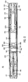
- the automatic injector assembly 10 includes a generally hollow housing 110.
- the housing 110 includes an injection insertion end 111 and an activation end 112.
- An actuator assembly 120 extends from an opening 113 in the activation end 112 of the housing 110.
- the actuator assembly 120 is slidably received within the housing 110.
- a removable end cap assembly 130 is releasably secured to the actuator assembly 120. When the end cap assembly 130 is secured to the actuator assembly 120, a side portion 131 of the end cap assembly 130 is adapted to abut the housing 110 to prevent movement of the actuator assembly 120 and unintentional injection of the medicament.
- the actuator assembly 120 includes a push button actuator assembly 121 having a hollow interior.
- the end cap assembly 130 engages the push button actuator assembly 121.
- a collet 122 is located within the hollow interior of the push button actuator assembly 121.
- An inner tube 123 is also located within the hollow interior of the push button actuator assembly 121.
- the inner tube 123 is adapted to contact the collet 122, as shown in Figs. 1 and 2.
- An opposite end of the inner tube 123 may include an engagement rib 1231 that is adapted to be received within a complementary recess 1211 within the push button actuator assembly 121.
- a drive assembly 124 is positioned within a space formed between the collet 122 and the inner tube 123.
- a pin 132 extends from the end cap assembly 130 and is received within the collet 122 to prevent or block the collet 122 from collapsing prior to activation.
- the drive assembly 124 Upon depression of the actuator assembly 121, the drive assembly 124 provides the necessary force when activated to operate the injector to inject the user with a necessary dosage of medicament. It is contemplated that the drive assembly 124 may be a spring assembly, a compressed gas assembly or any other suitable energy storing device. When activated, the drive assembly 124 causes the collet 122 to move such that a needle assembly 140 extends from an opening in the injection end 111 of the housing 110. Movement of the collet 122 also causes mixing of the dry medicament with the liquid injection solution, described in greater detail below.
- One end 1221 of the collet 122 extends into a wet container 150 located within the housing 110 for holding the liquid injection solution.
- the end 1221 of the collet 122 is adapted to contact a first plunger assembly 170 located within the wet container 150.
- the first plunger assembly 170 is adapted to engage the side wall of the wet container 150 to prevent leakage of the contents (e.g. liquid injection solution) of the wet container 150 from the activation end 112 of the housing 110.
- the first plunger assembly 170 is preferably formed from a material having low frictional properties such that the collet 122 and first plunger assembly 170 may easily slide within the wet container 150 when operated.
- the first plunger assembly 170 may be lubricated with silicon or other suitable non reactive lubricant.
- the movement of the collet 122 and the first plunger assembly 170 pressurizes the liquid located within the wet container 150.
- a suitable medicament is located within a dry container 160.
- a second plunger assembly 180 forms a barrier between the wet compartment 150 and the dry compartment 160.
- the second plunger assembly 180 prevents mixing of the dry medicament and liquid injection solution prior to activation of the automatic injector assembly.
- the second plunger assembly 180 is adapted to engage the side wall of the wet container 150 to prevent passage of the contents (e.g. liquid injection solution) of the wet container 150 into the dry compartment 160 prior to activation of the automatic injection assembly.
- the second plunger assembly 180 is preferably formed from a material having low frictional properties such that the second plunger assembly 180 may easily slide when operated.
- the second plunger assembly 180 may be lubricated with silicon or other suitable non reactive lubricant. The movement of the second plunger assembly 180 opens the fluid passage between the wet compartment and the dry compartment 160.
- the actuator assembly 120 releases the collet 122, which applies pressure on the first plunger assembly 170.
- the application of pressure on the first plunger assembly 170 by the collet and spring assembly 124 moves the first plunger assembly 170 in the direction of the needle assembly 140.
- the increased pressure within the wet compartment 150 moves the second plunger assembly 180 towards the needle assembly 140.
- This movement of the second plunger assembly 180 opens a fluid passageway 181 between the wet compartment 150 and the dry compartment 160. There is no compression of the dry medicament.
- the fluid passageway 181 may include recesses formed in the sidewall of the wet compartment 150 and the dry compartment 160, which open upon a predetermined movement of the second plunger assembly 180.
- the fluid passageway 181 may be formed by a reduced fit between the wet compartment 150 and the second plunger assembly 180, a series of by-pass slots, changes in diameter in the compartments 150 and 160, ribs on the container that distort the second plunger assembly or any other assembly that is capable of permitting that permit the flow of liquid injection solution around the second plunger assembly 180.
- a medicament support 190 is provided adjacent the end of the dry compartment 160 adjacent the needle assembly 140.
- the support 190 prevents blockage of the needle assembly 141 with dry medicament.
- the support 190 prevents the dry medicament from entering the area surrounding the needle assembly 140 while permitting passage of the mixture of dissolved medicament and liquid injection solution.
- the support 190 will be described in greater detail below. It is contemplated that multiple supports 190 may be located within the dry compartent 160. The provision of the supports 190 improves the laminar flow of the liquid injection solution through the dry medicament.
- a diaphragm assembly 200 may also be provided adjacent the medicament support 190.
- the diaphragm assembly 200 prevents the passage of the liquid injection solution to the needle assembly 140 prior to activation of the actuator assembly 120.
- the diaphragm assembly 200 does not rupture until sufficient pressure builds up whereby either the butt end of the needle assembly 140 or pressure build up rupture the diaphragm.
- the automatic injector assembly 20 includes a generally hollow housing 210.
- the housing 210 includes an injection insertion end located at nose cone assembly 211 and an activation end 212.
- an actuator assembly 120 extends from an opening 213 in the activation end 212 of the housing 210.
- the actuator assembly 120 is slidably received within the housing 110.
- a removable end cap assembly 130 is releasably secured to the actuator assembly 120. When the end cap assembly 130 is secured to the actuator assembly 120, a side portion 131 of the end cap assembly 130 is adapted to abut the housing 110 to prevent movement of the actuator assembly 120 and unintentional injection of the medicament.
- the drive assembly 124 provides the necessary force when activated to operate the injector assembly 20 to inject the user with a necessary dosage of medicament.
- the drive assembly 124 causes the collet 122 to move such that a needle assembly 140 extends from an opening in the nose cone assembly 211 of the housing 210.
- One end 1221 of the collet 122 extends into a wet container 150 located within the housing 210 for holding the liquid injection solution.
- the end 1221 of the collet 122 is adapted to contact a first plunger assembly 170 located within the wet container 150.
- the first plunger assembly 170 is adapted to engage the side wall of the wet container 150 to prevent leakage of the contents (e.g. liquid injection solution) of the wet container 150 from the activation end 212 of the housing 210.
- a second plunger assembly 280 forms a barrier between the wet compartment 150 and a dry compartment 160.
- the second plunger assembly 280 is adapted to engage the side wall of the wet container 150 to prevent passage of the contents (e.g. liquid injection solution) of the wet container 150 into the dry compartment 160 prior to activation of the automatic injection assembly.
- the second plunger assembly 280 includes a central cavity 281. One end of the cavity 281 is open into the wet container 150. An opposite end of the cavity is covered with a membrane assembly 282.
- the membrane assembly 282 provides a barrier between the wet compartment 150 and the dry compartment 160. Upon rupture of the membrane assembly 282, the liquid injection solution travels from the wet compartment 150 through the cavity 281 into the dry compartment 160. It is contemplated that the membrane assembly 282 may rupture either by a build up of pressure within the wet compartment 150 due to the movement of the first plunger assembly 170 or by contacting a projection or spike on medicament support, described below.
- the dry medicament located within the dry compartment 160 may be located between a pair of medicament supports 190.
- the supports 190 prevent the passage of undissolved dry medicament to the needle assembly 140 and the wet compartment 150.
- the supports 190 are described in greater detail below.
- the spring assembly 124 releases the collet 122, which applies pressure on the first plunger assembly 170.
- the application of pressure on the first plunger assembly 170 moves the first plunger assembly 170 in the direction of the needle assembly 140.
- the increased pressure within the wet compartment 150 moves the second plunger assembly 280 towards the needle assembly 140.
- the membrane 282 is ruptured when it contacts a projection 195 on one of the supports 190, as shown in Fig. 2.
- the liquid injection solution then flows through the cavity 281 to the dry compartment 160.
- the movement of the second plunger assembly 280 may also open at least one by-pass passageway 283 in the sidewall of the housing 210.
- the liquid injection solution mixes and dissolves with the dry medicament in the dry compartment 160.
- the mixture passes through the support 190 adjacent the needle assembly 140.
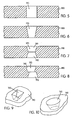
- Each support 190 is preferably formed from a single plate.
- the plate includes a plurality of openings or grooves 191 and 192 formed therein, as shown in Figs. 3 and 4.
- the grooves 191 and 192 are formed on opposite sides of the plate.
- the intersection of the grooves 191 and 192 form apertures 193.
- Each aperture 193 extends through the support 190 such that the liquid injection solution and the dissolved medicament may pass there through.
- the grooves 191 and 192 as shown, have an arcuate shape.
- the present invention is not limited to this configuration; rather, it is contemplated that any shaped groove may employed provided the grooves on one plate selectively overlap with the grooves on the other plate to form the above-described openings.
- the supports 190 may are provided with one or more tabs 194 extending from the perimeter of the plates. The optional tabs 194 are adapted to be received within complementary grooves, not shown, formed on the interior wall of the dry compartment 160 to maintain the lateral orientation of the supports 190 within the compartment 160. It is contemplated that the supports 190 may be formed from plastic, metal or any other suitable material provided the material does not react with the dry medicament during storage.
- the grooves 191 and 192 may be formed by machining, photo-etching, molding or any other suitable means. Additionally, it is contemplated that the apertures 193 may be formed without the use of the grooves 191 and 192; rather, the apertures 193 may be formed by machining, photo-etching, molding or any other suitable means.
- the dimensions and cross-sectional shape of the apertures 193 may vary. It is preferable that the apertures 193 be sized and shaped to prevent the passage of dry medicament there through.
- the apertures 193 in the medicament support 190 may be of such a shape so that the dry medicament fills and blocks the aperture to prevent the passage of the dry medicament prior to being dissolved by the liquid injection solution.
- the dry medicament enters the aperture and becomes compacted in the aperture due to the restriction in the cross-sectional area of the aperture, which clogs and closes the aperture until it is opened by the liquid injection solution.
- the apertures need not have a particular cross sectional shape.
- the apertures may be circular or square, as shown, for example, in Figs. 9 and 10.
- the apertures may have a gradual taper, as shown in Fig. 6, a taper that varies. as shown in Fig. 7 or an offset taper, as shown in Fig. 8. Any configuration is contemplated so long as the dry medicament is prevented from passing through the support. Numerous shapes and configurations are contemplated, as shown for example, in Figs. 5-8.
- the aperture 193 is sized to prevent the passage of undissolved medicament.
- the apertures 193 in Figs. 6-8 are sized and shaped to trap the undissolved medicament.
- the supports 190 may also include a central aperture 196. Although the supports 190, as described herein, are formed from a single plate, it is contemplated that the supports can be formed a pair of plates 191 and 192.
Landscapes
- Health & Medical Sciences (AREA)
- Vascular Medicine (AREA)
- Engineering & Computer Science (AREA)
- Anesthesiology (AREA)
- Biomedical Technology (AREA)
- Heart & Thoracic Surgery (AREA)
- Hematology (AREA)
- Life Sciences & Earth Sciences (AREA)
- Animal Behavior & Ethology (AREA)
- General Health & Medical Sciences (AREA)
- Public Health (AREA)
- Veterinary Medicine (AREA)
- Infusion, Injection, And Reservoir Apparatuses (AREA)
Applications Claiming Priority (2)
| Application Number | Priority Date | Filing Date | Title |
|---|---|---|---|
| US23844800P | 2000-10-10 | 2000-10-10 | |
| EP01983180A EP1324791B1 (fr) | 2000-10-10 | 2001-10-10 | Ensemble d'injection automatique de produit humide ou de produit sec |
Related Parent Applications (1)
| Application Number | Title | Priority Date | Filing Date |
|---|---|---|---|
| EP01983180A Division EP1324791B1 (fr) | 2000-10-10 | 2001-10-10 | Ensemble d'injection automatique de produit humide ou de produit sec |
Publications (2)
| Publication Number | Publication Date |
|---|---|
| EP1709984A2 true EP1709984A2 (fr) | 2006-10-11 |
| EP1709984A3 EP1709984A3 (fr) | 2006-10-18 |
Family
ID=36955193
Family Applications (1)
| Application Number | Title | Priority Date | Filing Date |
|---|---|---|---|
| EP06008388A Withdrawn EP1709984A3 (fr) | 2000-10-10 | 2001-10-10 | Ensemble injecteur automatique pour matière liquide / matière sèche |
Country Status (1)
| Country | Link |
|---|---|
| EP (1) | EP1709984A3 (fr) |
Cited By (3)
| Publication number | Priority date | Publication date | Assignee | Title |
|---|---|---|---|---|
| EP2144648A2 (fr) * | 2007-05-09 | 2010-01-20 | Meridian Medical Technologies, Inc. | Système d'administration d'une petite quantité d'agent thérapeutique |
| WO2010020800A1 (fr) * | 2008-08-18 | 2010-02-25 | The Medical House Plc | Auto-injecteur avec moyens mélangeurs |
| WO2012177948A2 (fr) | 2011-06-21 | 2012-12-27 | Brent Buchine | Dispositif mélangeur automatique et système de distribution |
Families Citing this family (1)
| Publication number | Priority date | Publication date | Assignee | Title |
|---|---|---|---|---|
| CZ303518B6 (cs) * | 2009-02-20 | 2012-11-07 | Vakos Xt A. S. | Tríkomorový automatický injektor |
Citations (6)
| Publication number | Priority date | Publication date | Assignee | Title |
|---|---|---|---|---|
| US3659749A (en) * | 1970-04-28 | 1972-05-02 | Boris Schwartz | Intermixing syringe |
| US4306554A (en) * | 1980-08-27 | 1981-12-22 | Boris Schwartz | Isolation storage and intermixing syringe for medicants |
| FR2604363A1 (fr) * | 1986-09-30 | 1988-04-01 | Merieux Inst | Dispositif d'injection de substances, notamment medicamenteuses |
| EP0405320A2 (fr) * | 1989-06-27 | 1991-01-02 | Elkom - Tovarna Stikalnih Naprav | Seringue d'injection automatique à usage multiple |
| FR2741810A1 (fr) * | 1995-11-30 | 1997-06-06 | Soc Et Et D Applic Tech Sedat | Seringue pour l'injection d'un melange extemporane |
| WO2001093925A2 (fr) * | 2000-06-08 | 2001-12-13 | Meridian Medical Technologies, Inc. | Ensemble injecteur automatique pour matiere liquide/matiere seche |
-
2001
- 2001-10-10 EP EP06008388A patent/EP1709984A3/fr not_active Withdrawn
Patent Citations (6)
| Publication number | Priority date | Publication date | Assignee | Title |
|---|---|---|---|---|
| US3659749A (en) * | 1970-04-28 | 1972-05-02 | Boris Schwartz | Intermixing syringe |
| US4306554A (en) * | 1980-08-27 | 1981-12-22 | Boris Schwartz | Isolation storage and intermixing syringe for medicants |
| FR2604363A1 (fr) * | 1986-09-30 | 1988-04-01 | Merieux Inst | Dispositif d'injection de substances, notamment medicamenteuses |
| EP0405320A2 (fr) * | 1989-06-27 | 1991-01-02 | Elkom - Tovarna Stikalnih Naprav | Seringue d'injection automatique à usage multiple |
| FR2741810A1 (fr) * | 1995-11-30 | 1997-06-06 | Soc Et Et D Applic Tech Sedat | Seringue pour l'injection d'un melange extemporane |
| WO2001093925A2 (fr) * | 2000-06-08 | 2001-12-13 | Meridian Medical Technologies, Inc. | Ensemble injecteur automatique pour matiere liquide/matiere seche |
Cited By (7)
| Publication number | Priority date | Publication date | Assignee | Title |
|---|---|---|---|---|
| EP2144648A2 (fr) * | 2007-05-09 | 2010-01-20 | Meridian Medical Technologies, Inc. | Système d'administration d'une petite quantité d'agent thérapeutique |
| EP2144648A4 (fr) * | 2007-05-09 | 2014-08-13 | Meridian Medical Technologies | Système d'administration d'une petite quantité d'agent thérapeutique |
| WO2010020800A1 (fr) * | 2008-08-18 | 2010-02-25 | The Medical House Plc | Auto-injecteur avec moyens mélangeurs |
| GB2462811B (en) * | 2008-08-18 | 2012-08-15 | Medical House Ltd | Improved autoinjector |
| WO2012177948A2 (fr) | 2011-06-21 | 2012-12-27 | Brent Buchine | Dispositif mélangeur automatique et système de distribution |
| EP2723426A2 (fr) * | 2011-06-21 | 2014-04-30 | Brent Buchine | Dispositif mélangeur automatique et système de distribution |
| EP2723426A4 (fr) * | 2011-06-21 | 2015-02-18 | Brent Buchine | Dispositif mélangeur automatique et système de distribution |
Also Published As
| Publication number | Publication date |
|---|---|
| EP1709984A3 (fr) | 2006-10-18 |
Similar Documents
| Publication | Publication Date | Title |
|---|---|---|
| EP1324791B1 (fr) | Ensemble d'injection automatique de produit humide ou de produit sec | |
| EP1324790B1 (fr) | Ensemble d'injection automatique humide/sec | |
| US20020049407A1 (en) | Wet/dry automatic injector assembly | |
| EP1292343B1 (fr) | Ensemble injecteur automatique pour matiere liquide/matiere seche | |
| DK169309B1 (da) | Automatisk injektionsindretning | |
| US7556614B2 (en) | Separation assembly for drug delivery device | |
| EP1709984A2 (fr) | Ensemble injecteur automatique pour matière liquide / matière sèche |
Legal Events
| Date | Code | Title | Description |
|---|---|---|---|
| PUAI | Public reference made under article 153(3) epc to a published international application that has entered the european phase |
Free format text: ORIGINAL CODE: 0009012 |
|
| PUAL | Search report despatched |
Free format text: ORIGINAL CODE: 0009013 |
|
| AC | Divisional application: reference to earlier application |
Ref document number: 1324791 Country of ref document: EP Kind code of ref document: P |
|
| AK | Designated contracting states |
Kind code of ref document: A2 Designated state(s): AT BE CH CY DE DK ES FI FR GB GR IE IT LI LU MC NL PT SE TR |
|
| AK | Designated contracting states |
Kind code of ref document: A3 Designated state(s): AT BE CH CY DE DK ES FI FR GB GR IE IT LI LU MC NL PT SE TR |
|
| RIN1 | Information on inventor provided before grant (corrected) |
Inventor name: HILL, ROBERT L. Inventor name: WILMOT, JOHN G. Inventor name: WHITTIER, JOHN |
|
| 17P | Request for examination filed |
Effective date: 20070327 |
|
| 17Q | First examination report despatched |
Effective date: 20070425 |
|
| AKX | Designation fees paid |
Designated state(s): AT BE CH CY DE DK ES FI FR GB GR IE IT LI LU MC NL PT SE TR |
|
| STAA | Information on the status of an ep patent application or granted ep patent |
Free format text: STATUS: THE APPLICATION IS DEEMED TO BE WITHDRAWN |
|
| 18D | Application deemed to be withdrawn |
Effective date: 20081007 |