EP1709333B2 - Vane system equipped with a guiding mechanism for centrifugal compressor - Google Patents
Vane system equipped with a guiding mechanism for centrifugal compressor Download PDFInfo
- Publication number
- EP1709333B2 EP1709333B2 EP04804362.4A EP04804362A EP1709333B2 EP 1709333 B2 EP1709333 B2 EP 1709333B2 EP 04804362 A EP04804362 A EP 04804362A EP 1709333 B2 EP1709333 B2 EP 1709333B2
- Authority
- EP
- European Patent Office
- Prior art keywords
- shaft
- vanes
- vane
- leverage
- row
- Prior art date
- Legal status (The legal status is an assumption and is not a legal conclusion. Google has not performed a legal analysis and makes no representation as to the accuracy of the status listed.)
- Ceased
Links
- 238000000034 method Methods 0.000 claims description 6
- 239000004809 Teflon Substances 0.000 claims description 4
- 229920006362 Teflon® Polymers 0.000 claims description 4
- 239000000314 lubricant Substances 0.000 claims description 2
- 230000014759 maintenance of location Effects 0.000 claims description 2
- 239000002245 particle Substances 0.000 claims description 2
- 238000007789 sealing Methods 0.000 claims description 2
- 239000010802 sludge Substances 0.000 claims description 2
- OKKJLVBELUTLKV-UHFFFAOYSA-N Methanol Chemical compound OC OKKJLVBELUTLKV-UHFFFAOYSA-N 0.000 description 6
- 238000004064 recycling Methods 0.000 description 5
- 230000015572 biosynthetic process Effects 0.000 description 4
- 238000003786 synthesis reaction Methods 0.000 description 4
- 230000001105 regulatory effect Effects 0.000 description 3
- 230000006833 reintegration Effects 0.000 description 3
- QGZKDVFQNNGYKY-UHFFFAOYSA-N Ammonia Chemical compound N QGZKDVFQNNGYKY-UHFFFAOYSA-N 0.000 description 2
- 230000033228 biological regulation Effects 0.000 description 2
- 239000012530 fluid Substances 0.000 description 2
- 229910021529 ammonia Inorganic materials 0.000 description 1
- 239000003831 antifriction material Substances 0.000 description 1
- 238000006243 chemical reaction Methods 0.000 description 1
- 230000001143 conditioned effect Effects 0.000 description 1
- 238000001125 extrusion Methods 0.000 description 1
- 238000009776 industrial production Methods 0.000 description 1
- 238000009434 installation Methods 0.000 description 1
- 238000012423 maintenance Methods 0.000 description 1
- 238000005086 pumping Methods 0.000 description 1
- 230000008929 regeneration Effects 0.000 description 1
- 238000011069 regeneration method Methods 0.000 description 1
Images


Classifications
-
- F—MECHANICAL ENGINEERING; LIGHTING; HEATING; WEAPONS; BLASTING
- F04—POSITIVE - DISPLACEMENT MACHINES FOR LIQUIDS; PUMPS FOR LIQUIDS OR ELASTIC FLUIDS
- F04D—NON-POSITIVE-DISPLACEMENT PUMPS
- F04D29/00—Details, component parts, or accessories
- F04D29/40—Casings; Connections of working fluid
- F04D29/42—Casings; Connections of working fluid for radial or helico-centrifugal pumps
- F04D29/44—Fluid-guiding means, e.g. diffusers
- F04D29/46—Fluid-guiding means, e.g. diffusers adjustable
- F04D29/462—Fluid-guiding means, e.g. diffusers adjustable especially adapted for elastic fluid pumps
-
- F—MECHANICAL ENGINEERING; LIGHTING; HEATING; WEAPONS; BLASTING
- F04—POSITIVE - DISPLACEMENT MACHINES FOR LIQUIDS; PUMPS FOR LIQUIDS OR ELASTIC FLUIDS
- F04D—NON-POSITIVE-DISPLACEMENT PUMPS
- F04D27/00—Control, e.g. regulation, of pumps, pumping installations or pumping systems specially adapted for elastic fluids
- F04D27/02—Surge control
- F04D27/0246—Surge control by varying geometry within the pumps, e.g. by adjusting vanes
-
- F—MECHANICAL ENGINEERING; LIGHTING; HEATING; WEAPONS; BLASTING
- F04—POSITIVE - DISPLACEMENT MACHINES FOR LIQUIDS; PUMPS FOR LIQUIDS OR ELASTIC FLUIDS
- F04D—NON-POSITIVE-DISPLACEMENT PUMPS
- F04D29/00—Details, component parts, or accessories
- F04D29/40—Casings; Connections of working fluid
- F04D29/42—Casings; Connections of working fluid for radial or helico-centrifugal pumps
- F04D29/4206—Casings; Connections of working fluid for radial or helico-centrifugal pumps especially adapted for elastic fluid pumps
- F04D29/4213—Casings; Connections of working fluid for radial or helico-centrifugal pumps especially adapted for elastic fluid pumps suction ports
-
- F—MECHANICAL ENGINEERING; LIGHTING; HEATING; WEAPONS; BLASTING
- F04—POSITIVE - DISPLACEMENT MACHINES FOR LIQUIDS; PUMPS FOR LIQUIDS OR ELASTIC FLUIDS
- F04D—NON-POSITIVE-DISPLACEMENT PUMPS
- F04D29/00—Details, component parts, or accessories
- F04D29/40—Casings; Connections of working fluid
- F04D29/42—Casings; Connections of working fluid for radial or helico-centrifugal pumps
- F04D29/44—Fluid-guiding means, e.g. diffusers
- F04D29/441—Fluid-guiding means, e.g. diffusers especially adapted for elastic fluid pumps
- F04D29/444—Bladed diffusers
-
- F—MECHANICAL ENGINEERING; LIGHTING; HEATING; WEAPONS; BLASTING
- F05—INDEXING SCHEMES RELATING TO ENGINES OR PUMPS IN VARIOUS SUBCLASSES OF CLASSES F01-F04
- F05D—INDEXING SCHEME FOR ASPECTS RELATING TO NON-POSITIVE-DISPLACEMENT MACHINES OR ENGINES, GAS-TURBINES OR JET-PROPULSION PLANTS
- F05D2250/00—Geometry
- F05D2250/50—Inlet or outlet
- F05D2250/51—Inlet
Definitions
- the present invention relates to a vane system equipped with a guiding mechanism, for a centrifugal compressor.
- the invention relates to a vane system for a centrifugal compressor with a cylindrical box, equipped with a guiding system.
- Adjustable vanes can be regulated/rotated in order to position them at a suitable angle with respect to the direction of the inlet fluid to be compressed.
- centrifugal compressors in industrial production and synthesis processes, is well known.
- the flexibility control of the plant is highly conditioned as, in this configuration, the reintegration and recycling phase are connected and there is no way of modifying the pressure ratio between the two phases, unless an anti-pumping system for both phases is installed.
- the compressor for the synthesis of methanol as in general, all compressors destined for synthesis process plants, are provided, in some cases, with a suction chamber equipped with adjustable vanes (IGV), whereas, in other cases, the performance control is effected by the regulation valve situated in the suction duct of the recycling phase.
- IGV adjustable vanes
- EP-A-0072701 , US-A-3799694 and US-A-5460484 disclose vane systems for centrifugal compressors in which two sets of guide vanes are positioned in the air inlet duct. The first set of vanes are fixed, while the second set are movable to vary their orientation.
- a general objective of the present invention is to overcome the above drawbacks relating to the lack of efficiency and control present in the plants according to the known art, by providing a vane system for centrifugal compressors (IGV) suitable for improving performance control and efficiency.
- IGV centrifugal compressors
- Another objective of the present invention is to allow a better handling of the plant, thanks to the separate running of the regeneration and recycling streams.
- Yet another objective of the present invention is to allow different operative conditions of the machine.
- the mechanism of the present invention advantageously avoids the installation of a costly regulation valve.
- the mechanism allows a high flexibility of the process reactor.
- the recycling step is advantageously improved as far as efficiency is concerned.
- the vane system for a centrifugal compressor comprises two rows of vanes installed in series inside a suction duct, the first row of fixed vanes being suitable for homogenizing the gas flow passing through them and sending it to the second row equipped with a guiding mechanism comprising a mechanical system suitable for varying the orientation of the vanes of said second row.
- a centrifugal compressor 10 is equipped with a shaft 11, on which a series of rotors 12, equipped with relative vanes, is installed.
- a vane system comprising two different rows of vanes, is installed at the inlet of the suction duct 14, immediately after the suction chamber 13.
- a first set 15 comprises fixed vanes 15', fixed to a vane-holder ring 17, by means of roots 16, situated in the conveyor, in turn connected to the terminal section 18' of the compressor box 18, by means of bolting with a stud 19.
- a second set of vanes 20 is made up of adjustable vanes 20', also known with the Anglo-Saxon acronym IGV (Inlet Guide Vanes).
- IGV Inlet Guide Vanes
- the adjustable vanes can be regulated/rotated in order to position them at a suitable angle, with respect to the direction of the fluid entering the compressor, so as to vary the compressor inlet flow rate.
- the second set 20 of adjustable vanes 20' receives a stream homogenized by the first set of fixed vanes 15, and is positioned downstream of said first set in the duct 14.
- the second set 20 of adjustable vanes 20' is equipped with a mechanical system 30 suitable for regulating the orientation of the adjustable vanes 20' so as to vary the incidence angle on the rotor, thus modifying the flow gradient and exhaust pressure, regardless of the reintegration phase.
- mechanical system is partially positioned inside the terminal section 18' of the compressor box 18 and passes through this to connect itself to an actuator 70, preferably of the pneumatic type, situated outside the box.
- the mechanical system 30 envisages the connection of each adjustable vane 20' of the second set 20, to a shaft 33 by means of a first leverage 51 suitable for receiving the rotation effected by the actuator 70 to transmit it to the vanes 20'.
- the kinematic chain of the mechanical system 30 for guiding the adjustable vanes 20' of the second set 20, therefore includes the connection of each adjustable vane 20' by means of its foot 50, produced in the form of a shaft, to the first leverage 51, in turn connected by means of the rotating ring pin 52, to a disk 53.
- the disk 53 receives the rotation movement provided by the shaft 33 by means of a second leverage 81 connected to the opposite side of disk 53.
- the first leverage 51 comprises a lever 54 fixed at one end to said foot of the adjustable vane 20' and hinged at the other end to a tie rod 55 by means of rotating ring pin 56.
- the tie rod 55 is, in turn, hinged to the disk 53, as already mentioned, in order to receive the rotational movement of the shaft 33.
- the second leverage 81 includes a lever 84 fixed at one end to said shaft 33 and hinged at the other end to a tie rod 85 by means of the rotating ring pin 86.
- the tie rod 85 is, in turn, hinged to the disk 53, as already mentioned, in order to receive the rotational movement of the shaft 33.
- the shaft 33 in contact with the tie rod 85, is equipped with a thrust rim 34 which rests on bushings 38 coated with antifriction treatment.
- the shaft is advantageously divided into two portions, a first portion 33' towards the vanes, and a second portion 33" outwards, connected by means of the joint 57 to facilitate dismantling and maintenance.
- a ring 41 is placed at the end of the first portion 33' of said shaft 33, close to the joint, equipped with Teflon washers 37, and a spring in order to retain the process gas inside the box 18.
- a further ring 41 equipped with o-ring washers 36, is positioned downstream to retain the lubricant vapors 40 present.
- Anti-extrusion rings for example made of Teflon, and charged springs 37, again made of Teflon, are also present close to the end of the first portion 33' of the shaft 33.
- the shaft is equipped with bushings coated with antifriction material 38 to allow easy rotation, and with at least one sealing ring 44 which serves to keep the dirty particles and sludge out of the box.
- a spiral coil 39 envelops the shaft body to keep it in a stand-by position and rests on a retention body 35 which rubs against the shaft itself, with the interposition of antifriction bushings 38.
- the end of the second portion 33" of the shaft 33 which protrudes outside the box 18 is connected to an actuation and control system 60 comprising the actuator 70 which transmits rotation upon command, a third leverage 61 substantially similar to the first and second leverage 51 and 81, and a reading system of the inclination angle of the vanes 20'.
- the reading system is activated by means of the actuator which provides the shaft, and consequently the vanes, with a rotational movement, and the reading of the orientation for the vanes 20' is effected by means of a reference index 63 fixed to the leverage 61 and which cooperates with a graduated label 42 fixed, for example, to the ring 41.
Landscapes
- Engineering & Computer Science (AREA)
- Mechanical Engineering (AREA)
- General Engineering & Computer Science (AREA)
- Physics & Mathematics (AREA)
- Geometry (AREA)
- Structures Of Non-Positive Displacement Pumps (AREA)
- Control Of Positive-Displacement Air Blowers (AREA)
Description
- The present invention relates to a vane system equipped with a guiding mechanism, for a centrifugal compressor.
- In particular, the invention relates to a vane system for a centrifugal compressor with a cylindrical box, equipped with a guiding system.
- Among the numerous applications of centrifugal compressors, those which require the presence of adjustable vanes at the inlet of the compressor, also known with the acronym of IGV (Inlet Guide Vanes) are familiar.
- Adjustable vanes (IGV) can be regulated/rotated in order to position them at a suitable angle with respect to the direction of the inlet fluid to be compressed.
- The use of centrifugal compressors in industrial production and synthesis processes, is well known.
- Among the various applications, those operating on two different streams inside the same compressor, such as, for example, in the synthesis of ammonia and methanol, are also known. In the latter plants, a two-phase compressor is used, wherein the first phase consists of reaction reintegration and the second of reactor recycling.The suction pressure and composition are different in the two streams.
- The flexibility control of the plant is highly conditioned as, in this configuration, the reintegration and recycling phase are connected and there is no way of modifying the pressure ratio between the two phases, unless an anti-pumping system for both phases is installed.
- In the plants according to the known art, the compressor for the synthesis of methanol, as in general, all compressors destined for synthesis process plants, are provided, in some cases, with a suction chamber equipped with adjustable vanes (IGV), whereas, in other cases, the performance control is effected by the regulation valve situated in the suction duct of the recycling phase.
- The latter solution is considered obsolete and has various disadvantages, in particular with respect to efficiency and control.
-
EP-A-0072701 ,US-A-3799694 andUS-A-5460484 disclose vane systems for centrifugal compressors in which two sets of guide vanes are positioned in the air inlet duct. The first set of vanes are fixed, while the second set are movable to vary their orientation. - A general objective of the present invention is to overcome the above drawbacks relating to the lack of efficiency and control present in the plants according to the known art, by providing a vane system for centrifugal compressors (IGV) suitable for improving performance control and efficiency.
- Another objective of the present invention is to allow a better handling of the plant, thanks to the separate running of the regeneration and recycling streams.
- Yet another objective of the present invention is to allow different operative conditions of the machine.
- The mechanism of the present invention advantageously avoids the installation of a costly regulation valve.
- Moreover, the mechanism allows a high flexibility of the process reactor.
- In addition, the recycling step is advantageously improved as far as efficiency is concerned.
- These and other objectives and advantages, according to the present invention, are achieved by means of a vane system for a centrifugal compressor, equipped with a guiding mechanism, according to what is disclosed in
claim 1. - Further specific characteristics are present in the dependant claims.
- The vane system for a centrifugal compressor according to the invention comprises two rows of vanes installed in series inside a suction duct, the first row of fixed vanes being suitable for homogenizing the gas flow passing through them and sending it to the second row equipped with a guiding mechanism comprising a mechanical system suitable for varying the orientation of the vanes of said second row.
- The characteristics and advantages of a vane system equipped with a guiding mechanism for a centrifugal compressor, according to the present invention, will appear more evident from the following illustrative and nonlimiting description, referring to the enclosed schematic drawings, wherein:
-
figure 1 is a partially sectional side schematic view of a compressor comprising the mechanism according to the invention; -
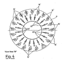
figure 2 shows the vane system according to the invention; -
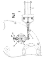
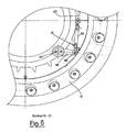
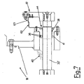
figures 3 to 7 show different details of the system according to the invention; -
figures 8 and 9 show respectively in elevation view and in plan view a double leverage of the mechanism of the system according to the invention. - With reference to the figures, a
centrifugal compressor 10 is equipped with ashaft 11, on which a series ofrotors 12, equipped with relative vanes, is installed. - A
suction chamber 13, from which the gas is fed to the first stage of the compressor by means of thesuction duct 14, is situated at the inlet of thecompressor 10. - A vane system, comprising two different rows of vanes, is installed at the inlet of the
suction duct 14, immediately after thesuction chamber 13. - A
first set 15 comprises fixed vanes 15', fixed to a vane-holder ring 17, by means ofroots 16, situated in the conveyor, in turn connected to the terminal section 18' of thecompressor box 18, by means of bolting with astud 19. - A second set of
vanes 20 is made up of adjustable vanes 20', also known with the Anglo-Saxon acronym IGV (Inlet Guide Vanes). - The adjustable vanes (IGV) can be regulated/rotated in order to position them at a suitable angle, with respect to the direction of the fluid entering the compressor, so as to vary the compressor inlet flow rate.
- The
second set 20 of adjustable vanes 20' receives a stream homogenized by the first set of fixedvanes 15, and is positioned downstream of said first set in theduct 14. - The
second set 20 of adjustable vanes 20' is equipped with amechanical system 30 suitable for regulating the orientation of the adjustable vanes 20' so as to vary the incidence angle on the rotor, thus modifying the flow gradient and exhaust pressure, regardless of the reintegration phase. - Said.mechanical system is partially positioned inside the terminal section 18' of the
compressor box 18 and passes through this to connect itself to anactuator 70, preferably of the pneumatic type, situated outside the box. - The
mechanical system 30 envisages the connection of each adjustable vane 20' of thesecond set 20, to ashaft 33 by means of afirst leverage 51 suitable for receiving the rotation effected by theactuator 70 to transmit it to the vanes 20'. - The kinematic chain of the
mechanical system 30 for guiding the adjustable vanes 20' of thesecond set 20, therefore includes the connection of each adjustable vane 20' by means of itsfoot 50, produced in the form of a shaft, to thefirst leverage 51, in turn connected by means of the rotatingring pin 52, to adisk 53. - The
disk 53 receives the rotation movement provided by theshaft 33 by means of asecond leverage 81 connected to the opposite side ofdisk 53. - With particular reference to
figures 8 and 9 , these illustrate thefirst leverage 51, and with reference tofigure 6 , this shows thesecond leverage 81 applied to the disk. - The
first leverage 51 comprises alever 54 fixed at one end to said foot of the adjustable vane 20' and hinged at the other end to atie rod 55 by means of rotatingring pin 56. - The
tie rod 55 is, in turn, hinged to thedisk 53, as already mentioned, in order to receive the rotational movement of theshaft 33. - In the same way, the
second leverage 81 includes alever 84 fixed at one end to saidshaft 33 and hinged at the other end to atie rod 85 by means of the rotatingring pin 86. - The
tie rod 85 is, in turn, hinged to thedisk 53, as already mentioned, in order to receive the rotational movement of theshaft 33. - The
shaft 33, in contact with thetie rod 85, is equipped with athrust rim 34 which rests onbushings 38 coated with antifriction treatment. - The shaft is advantageously divided into two portions, a first portion 33' towards the vanes, and a
second portion 33" outwards, connected by means of thejoint 57 to facilitate dismantling and maintenance. - A
ring 41 is placed at the end of the first portion 33' of saidshaft 33, close to the joint, equipped with Teflonwashers 37, and a spring in order to retain the process gas inside thebox 18. - A
further ring 41, equipped with o-ring washers 36, is positioned downstream to retain thelubricant vapors 40 present. - Anti-extrusion rings, for example made of Teflon, and charged
springs 37, again made of Teflon, are also present close to the end of the first portion 33' of theshaft 33. - The shaft is equipped with bushings coated with
antifriction material 38 to allow easy rotation, and with at least onesealing ring 44 which serves to keep the dirty particles and sludge out of the box. - A
spiral coil 39 envelops the shaft body to keep it in a stand-by position and rests on a retention body 35 which rubs against the shaft itself, with the interposition ofantifriction bushings 38. - The end of the
second portion 33" of theshaft 33 which protrudes outside thebox 18 is connected to an actuation andcontrol system 60 comprising theactuator 70 which transmits rotation upon command, athird leverage 61 substantially similar to the first andsecond leverage - The reading system is activated by means of the actuator which provides the shaft, and consequently the vanes, with a rotational movement, and the reading of the orientation for the vanes 20' is effected by means of a
reference index 63 fixed to theleverage 61 and which cooperates with a graduated label 42 fixed, for example, to thering 41. - In this way it is possible to control and impart the pre-defined rotation, both clockwise and anti-clockwise, to the vanes 20' of the second row of
vanes 20, so as to optimize the efficiency of the stream to be compressed.
Claims (10)
- A vane system for a centrifugal compressor (10), which comprises two rows (15, 20) of vanes (15', 20') installed in series inside a suction duct (14), the first row (15) of fixed vanes (15') being suitable for homogenizing the gas flow passing through them and sending it to a second row (20) of adjustable vanes (20'), said second row being equipped with a guiding mechanism comprising a mechanical system (30) suitable for varying the orientation of the vanes (20'), characterized in that the guiding mechanical system (30) comprises the connection of each adjustable vane (20') of the second row (20) to a shaft (33) by means of a first leverage (51) suitable for receiving the rotation imparted by an actuator (70), and each adjustable vane (20') is connected, through its foot (50) produced in the form of a shaft, to the first leverage (51), in turn connected by means of a rotating ring pin (52), to disk (53) which receives the rotational movement induced by the shaft (33), wherein said first leverage is a double leverage (51) comprising a lever (54) fixed at one end to said foot of the adjustable vane (20') and hinged at the other end to a tie rod (55) by means of a rotating ring pin (56), the tie rod (55) being hinged to the disk (53) which receives the rotational movement induced by the shaft (33), and the shaft (33) being connected to said disk (53) by means of a second leverage (81).
- The vane system according to claim 1, wherein said first row (15) of fixed vanes (15') is fixed by means of roots (16) to the structure (17) of the diffuser, in turn connected to the terminal portion (18') of the compressor box (18).
- The vane system according to claim 1, wherein the second row (20) of adjustable vanes (20') equipped with the mechanical system (30), is activated by a pneumatic actuator (70), suitable for varying the orientation of the vanes so as to vary the incidence angle on the rotor, thus modifying the flow gradient and discharge pressure.
- The vane system according to claim 1, wherein said shaft (33) is equipped with a thrust rim (34) which rests on bushings (38) coated with antifriction treatment.
- The vane system according to claim 1, wherein said shaft is divided into two portions, a first portion (33') towards the vanes, and a second portion (33") outwards, connected by means of the joint (57).
- The vane system according to claim 5, wherein a ring (41) is positioned at the end of the first portion (33') of said shaft (33), close to the joint (57), equipped with Teflon washers (37), energized with a spring to retain the process gas inside the box (18), and a further tain the process gas inside the box (18), and a further ring (41), equipped with o-ring washers (36), is situated downstream, to retain the lubricant vapors (40) present.
- The vane system according to claim 1, wherein the shaft (33) is also equipped with at least one sealing ring (44) which serves to keep the dirty particles and sludge out of the box (18).
- The vane system according to claim 1, wherein there is also a spiral coil (39) which envelops the shaft body (33) to keep it in a stand-by position, and which rests on a retention body (35) which rubs against the shaft itself, with the interposition of antifriction bushings (38).
- The vane system according to claim 1, wherein the end of the second portion (33") of the shaft (33) which protrudes outside the box (18) is connected to an actuation and control system (60) comprising the actuator (70) which transmits rotation upon command, a third leverage (61) substantially similar to the first two leverages (51, 81) and a reading system of the inclination angle of the vanes (20').
- The vane system according to claim 9, wherein the reading of the orientation imparted to the vanes (20') of the second row (20) is effected by means of a reference index (63) fixed to the third leverage (61) and which cooperates with a graduated label (42) fixed, for example, to the ring (41).
Applications Claiming Priority (2)
| Application Number | Priority Date | Filing Date | Title |
|---|---|---|---|
| IT002608A ITMI20032608A1 (en) | 2003-12-29 | 2003-12-29 | CENTRIFUGAL COMPRESSOR PALETTE SYSTEM WITH REGULATION MECHANISM |
| PCT/EP2004/014775 WO2005064168A1 (en) | 2003-12-29 | 2004-12-22 | Vane system equipped with a guiding mechanism for centrifugal compressor |
Publications (3)
| Publication Number | Publication Date |
|---|---|
| EP1709333A1 EP1709333A1 (en) | 2006-10-11 |
| EP1709333B1 EP1709333B1 (en) | 2009-03-25 |
| EP1709333B2 true EP1709333B2 (en) | 2014-04-09 |
Family
ID=34717635
Family Applications (1)
| Application Number | Title | Priority Date | Filing Date |
|---|---|---|---|
| EP04804362.4A Ceased EP1709333B2 (en) | 2003-12-29 | 2004-12-22 | Vane system equipped with a guiding mechanism for centrifugal compressor |
Country Status (8)
| Country | Link |
|---|---|
| US (1) | US7520716B2 (en) |
| EP (1) | EP1709333B2 (en) |
| JP (1) | JP5038720B2 (en) |
| CN (1) | CN100467877C (en) |
| DE (1) | DE602004020268D1 (en) |
| IT (1) | ITMI20032608A1 (en) |
| NO (1) | NO339532B1 (en) |
| WO (1) | WO2005064168A1 (en) |
Families Citing this family (19)
| Publication number | Priority date | Publication date | Assignee | Title |
|---|---|---|---|---|
| DE102007002779A1 (en) * | 2007-01-18 | 2008-07-31 | Linde Ag | Process for liquefying a hydrocarbon-rich stream |
| US8033782B2 (en) * | 2008-01-16 | 2011-10-11 | Elliott Company | Method to prevent brinelling wear of slot and pin assembly |
| US8231326B2 (en) * | 2009-03-31 | 2012-07-31 | Nuovo Pignone S.P.A. | Nozzle adjusting mechanism and method |
| US11246585B2 (en) | 2009-07-17 | 2022-02-15 | Stryker Puerto Rico Limited | Method and apparatus for attaching tissue to bone, including the provision and use of a novel knotless suture anchor system |
| IT1396512B1 (en) | 2009-10-21 | 2012-12-14 | Nuovo Pignone Spa | METHOD AND DEVICE FOR TOOL COMPENSATION |
| US8632302B2 (en) * | 2009-12-07 | 2014-01-21 | Dresser-Rand Company | Compressor performance adjustment system |
| ITCO20110034A1 (en) | 2011-08-31 | 2013-03-01 | Nuovo Pignone Spa | IGV COMPACT FOR APPLICATION IN TURBOESPANSORE |
| ITCO20110037A1 (en) | 2011-09-09 | 2013-03-10 | Nuovo Pignone Spa | SEALING SYSTEM FOR ACTUATOR AND METHOD |
| EP2604960A1 (en) | 2011-12-15 | 2013-06-19 | Shell Internationale Research Maatschappij B.V. | Method of operating a compressor and system and method for producing a liquefied hydrocarbon stream |
| CN102619736A (en) * | 2012-04-16 | 2012-08-01 | 杭州杭氧透平机械有限公司 | Executive mechanism of air-intake-adjustable flow guide cascade of oxygen compressor |
| US9004850B2 (en) | 2012-04-27 | 2015-04-14 | Pratt & Whitney Canada Corp. | Twisted variable inlet guide vane |
| JP6206638B2 (en) * | 2012-11-15 | 2017-10-04 | 三菱重工サーマルシステムズ株式会社 | Centrifugal compressor |
| US10024335B2 (en) | 2014-06-26 | 2018-07-17 | General Electric Company | Apparatus for transferring energy between a rotating element and fluid |
| US10030669B2 (en) * | 2014-06-26 | 2018-07-24 | General Electric Company | Apparatus for transferring energy between a rotating element and fluid |
| JP6781155B2 (en) * | 2015-01-28 | 2020-11-04 | ヌオーヴォ・ピニォーネ・テクノロジー・ソチエタ・レスポンサビリタ・リミタータNuovo Pignone Tecnologie S.R.L. | Devices, turbomachinery and methods for controlling the flow of turbomachinery |
| CN107975498B (en) | 2016-10-24 | 2021-08-31 | 开利公司 | Diffuser for centrifugal compressor and centrifugal compressor with diffuser |
| US10704411B2 (en) | 2018-08-03 | 2020-07-07 | General Electric Company | Variable vane actuation system for a turbo machine |
| AU2020376271B9 (en) * | 2019-10-31 | 2023-11-09 | Daikin Industries, Ltd. | Inlet guide vane actuator assembly |
| US11401947B2 (en) * | 2020-10-30 | 2022-08-02 | Praxair Technology, Inc. | Hydrogen centrifugal compressor |
Citations (2)
| Publication number | Priority date | Publication date | Assignee | Title |
|---|---|---|---|---|
| US2733853A (en) † | 1956-02-07 | trumpler | ||
| GB820595A (en) † | 1956-05-31 | 1959-09-23 | Garrett Corp | Improvements relating to turbine nozzles |
Family Cites Families (19)
| Publication number | Priority date | Publication date | Assignee | Title |
|---|---|---|---|---|
| US2860827A (en) * | 1953-06-08 | 1958-11-18 | Garrett Corp | Turbosupercharger |
| US3237918A (en) * | 1963-08-30 | 1966-03-01 | Gen Electric | Variable stator vanes |
| US3442493A (en) | 1965-10-22 | 1969-05-06 | Gen Electric | Articulated airfoil vanes |
| US3458118A (en) * | 1967-08-21 | 1969-07-29 | Gen Electric | Low profile stator adjusting mechanism |
| US3799694A (en) * | 1972-11-20 | 1974-03-26 | Gen Motors Corp | Variable diffuser |
| DE2502986C2 (en) * | 1975-01-25 | 1985-04-11 | M.A.N. Maschinenfabrik Augsburg-Nürnberg AG, 4200 Oberhausen | Device for adjusting the swirl blades of a turbo compressor |
| US3990809A (en) * | 1975-07-24 | 1976-11-09 | United Technologies Corporation | High ratio actuation linkage |
| JPS6053200B2 (en) * | 1979-01-29 | 1985-11-25 | 三菱重工業株式会社 | centrifugal fan |
| GB2078865B (en) * | 1980-06-28 | 1983-06-08 | Rolls Royce | A variable stator vane operating mechanism for a gas turbine engine |
| US4428714A (en) * | 1981-08-18 | 1984-01-31 | A/S Kongsberg Vapenfabrikk | Pre-swirl inlet guide vanes for compressor |
| JPS62200U (en) * | 1985-06-18 | 1987-01-06 | ||
| US4804316A (en) * | 1985-12-11 | 1989-02-14 | Allied-Signal Inc. | Suspension for the pivoting vane actuation mechanism of a variable nozzle turbocharger |
| US5190439A (en) * | 1991-07-15 | 1993-03-02 | United Technologies Corporation | Variable vane non-linear schedule for a gas turbine engine |
| JP2797898B2 (en) | 1993-05-26 | 1998-09-17 | 日産自動車株式会社 | Variable inlet guide vane for compressor |
| JP2558572Y2 (en) * | 1993-08-03 | 1997-12-24 | シーケーディ株式会社 | Hydrostatic cylinder |
| JP2891884B2 (en) * | 1994-11-29 | 1999-05-17 | シーケーディ株式会社 | Air bearing cylinder and cylinder system |
| JPH10266896A (en) * | 1997-03-26 | 1998-10-06 | Ishikawajima Harima Heavy Ind Co Ltd | Compressor casing of jet engine |
| JP4166996B2 (en) * | 2002-03-28 | 2008-10-15 | 三菱重工業株式会社 | Capacity control drive mechanism of turbo refrigerator |
| US6994518B2 (en) * | 2002-11-13 | 2006-02-07 | Borgwarner Inc. | Pre-whirl generator for radial compressor |
-
2003
- 2003-12-29 IT IT002608A patent/ITMI20032608A1/en unknown
-
2004
- 2004-12-22 JP JP2006546098A patent/JP5038720B2/en not_active Expired - Fee Related
- 2004-12-22 CN CNB2004800394493A patent/CN100467877C/en not_active Expired - Fee Related
- 2004-12-22 US US10/596,898 patent/US7520716B2/en active Active
- 2004-12-22 DE DE602004020268T patent/DE602004020268D1/en active Active
- 2004-12-22 EP EP04804362.4A patent/EP1709333B2/en not_active Ceased
- 2004-12-22 WO PCT/EP2004/014775 patent/WO2005064168A1/en not_active Application Discontinuation
-
2006
- 2006-07-21 NO NO20063388A patent/NO339532B1/en not_active IP Right Cessation
Patent Citations (2)
| Publication number | Priority date | Publication date | Assignee | Title |
|---|---|---|---|---|
| US2733853A (en) † | 1956-02-07 | trumpler | ||
| GB820595A (en) † | 1956-05-31 | 1959-09-23 | Garrett Corp | Improvements relating to turbine nozzles |
Also Published As
| Publication number | Publication date |
|---|---|
| CN100467877C (en) | 2009-03-11 |
| JP2007517159A (en) | 2007-06-28 |
| US20070166149A1 (en) | 2007-07-19 |
| EP1709333B1 (en) | 2009-03-25 |
| ITMI20032608A1 (en) | 2005-06-30 |
| US7520716B2 (en) | 2009-04-21 |
| NO339532B1 (en) | 2016-12-27 |
| WO2005064168A1 (en) | 2005-07-14 |
| JP5038720B2 (en) | 2012-10-03 |
| CN1902403A (en) | 2007-01-24 |
| NO20063388L (en) | 2006-09-21 |
| EP1709333A1 (en) | 2006-10-11 |
| DE602004020268D1 (en) | 2009-05-07 |
| WO2005064168A8 (en) | 2005-10-06 |
Similar Documents
| Publication | Publication Date | Title |
|---|---|---|
| EP1709333B2 (en) | Vane system equipped with a guiding mechanism for centrifugal compressor | |
| EP0384706B1 (en) | Variable inlet guide vanes for a compressor | |
| US20100172744A1 (en) | Variable position guide vane actuation system and method | |
| EP2659096B1 (en) | Variable vane for gas turbine engine | |
| US6582190B2 (en) | Variable-capacity turbine | |
| JP3682976B2 (en) | Cylindrical bleeder valve opening in the axial direction | |
| EP1888881B1 (en) | Variable geometry turbine | |
| CN102159794B (en) | Method, system, device for variable guide vanes | |
| EP2735351B1 (en) | Centrifugal separator for separating particles from a gas stream | |
| US8740547B2 (en) | System for controlling variable geometry equipment of a gas turbine engine particularly comprising a barrel link | |
| EP2922609B1 (en) | A centrifugal separator | |
| EP1411281B1 (en) | Butterfly valve | |
| PL167025B1 (en) | Steam turbine inlet housing | |
| CN1030210C (en) | Axial flow turbine | |
| US8690520B2 (en) | System for controlling variable geometry equipment of a gas turbine engine especially comprising a guiding track connection | |
| EP2204550A2 (en) | Variable position guide vane actuation system and method | |
| JP2010071140A (en) | Variable displacement turbocharger | |
| EP3502485A1 (en) | Adjustment linkage | |
| JP2000510216A (en) | Steam turbine | |
| EP3502484A1 (en) | Adjustment linkage | |
| CN111527293B (en) | Compressor control | |
| GB2463660A (en) | Radial flow turbine | |
| JPS5979005A (en) | Axial-flow turbine having widthwise-flow type speed governing step attached with variable nozzle |
Legal Events
| Date | Code | Title | Description |
|---|---|---|---|
| PUAI | Public reference made under article 153(3) epc to a published international application that has entered the european phase |
Free format text: ORIGINAL CODE: 0009012 |
|
| 17P | Request for examination filed |
Effective date: 20060731 |
|
| AK | Designated contracting states |
Kind code of ref document: A1 Designated state(s): CH DE FR GB LI NL |
|
| DAX | Request for extension of the european patent (deleted) | ||
| RBV | Designated contracting states (corrected) |
Designated state(s): CH DE FR GB LI NL |
|
| 17Q | First examination report despatched |
Effective date: 20070615 |
|
| GRAP | Despatch of communication of intention to grant a patent |
Free format text: ORIGINAL CODE: EPIDOSNIGR1 |
|
| GRAS | Grant fee paid |
Free format text: ORIGINAL CODE: EPIDOSNIGR3 |
|
| GRAA | (expected) grant |
Free format text: ORIGINAL CODE: 0009210 |
|
| AK | Designated contracting states |
Kind code of ref document: B1 Designated state(s): CH DE FR GB LI NL |
|
| REG | Reference to a national code |
Ref country code: GB Ref legal event code: FG4D |
|
| REG | Reference to a national code |
Ref country code: CH Ref legal event code: EP Ref country code: CH Ref legal event code: NV Representative=s name: SERVOPATENT GMBH |
|
| REF | Corresponds to: |
Ref document number: 602004020268 Country of ref document: DE Date of ref document: 20090507 Kind code of ref document: P |
|
| PLBI | Opposition filed |
Free format text: ORIGINAL CODE: 0009260 |
|
| PLAX | Notice of opposition and request to file observation + time limit sent |
Free format text: ORIGINAL CODE: EPIDOSNOBS2 |
|
| 26 | Opposition filed |
Opponent name: SIEMENS AKTIENGESELLSCHAFT Effective date: 20091223 |
|
| NLR1 | Nl: opposition has been filed with the epo |
Opponent name: SIEMENS AKTIENGESELLSCHAFT |
|
| PLAF | Information modified related to communication of a notice of opposition and request to file observations + time limit |
Free format text: ORIGINAL CODE: EPIDOSCOBS2 |
|
| PLBB | Reply of patent proprietor to notice(s) of opposition received |
Free format text: ORIGINAL CODE: EPIDOSNOBS3 |
|
| RIC2 | Information provided on ipc code assigned after grant |
Ipc: F04D 27/02 20060101ALI20130708BHEP Ipc: F04D 29/46 20060101AFI20130708BHEP |
|
| PUAH | Patent maintained in amended form |
Free format text: ORIGINAL CODE: 0009272 |
|
| STAA | Information on the status of an ep patent application or granted ep patent |
Free format text: STATUS: PATENT MAINTAINED AS AMENDED |
|
| 27A | Patent maintained in amended form |
Effective date: 20140409 |
|
| AK | Designated contracting states |
Kind code of ref document: B2 Designated state(s): CH DE FR GB LI NL |
|
| REG | Reference to a national code |
Ref country code: DE Ref legal event code: R102 Ref document number: 602004020268 Country of ref document: DE |
|
| REG | Reference to a national code |
Ref country code: CH Ref legal event code: AELC |
|
| REG | Reference to a national code |
Ref country code: DE Ref legal event code: R102 Ref document number: 602004020268 Country of ref document: DE Effective date: 20140409 |
|
| REG | Reference to a national code |
Ref country code: NL Ref legal event code: T3 |
|
| REG | Reference to a national code |
Ref country code: DE Ref legal event code: R082 Ref document number: 602004020268 Country of ref document: DE |
|
| PGFP | Annual fee paid to national office [announced via postgrant information from national office to epo] |
Ref country code: NL Payment date: 20141226 Year of fee payment: 11 |
|
| REG | Reference to a national code |
Ref country code: FR Ref legal event code: PLFP Year of fee payment: 12 |
|
| REG | Reference to a national code |
Ref country code: NL Ref legal event code: MM Effective date: 20160101 |
|
| PG25 | Lapsed in a contracting state [announced via postgrant information from national office to epo] |
Ref country code: NL Free format text: LAPSE BECAUSE OF NON-PAYMENT OF DUE FEES Effective date: 20160101 |
|
| REG | Reference to a national code |
Ref country code: FR Ref legal event code: PLFP Year of fee payment: 13 |
|
| REG | Reference to a national code |
Ref country code: FR Ref legal event code: PLFP Year of fee payment: 14 |
|
| PGFP | Annual fee paid to national office [announced via postgrant information from national office to epo] |
Ref country code: DE Payment date: 20181126 Year of fee payment: 15 |
|
| PGFP | Annual fee paid to national office [announced via postgrant information from national office to epo] |
Ref country code: CH Payment date: 20181126 Year of fee payment: 15 Ref country code: FR Payment date: 20181127 Year of fee payment: 15 Ref country code: GB Payment date: 20181127 Year of fee payment: 15 |
|
| REG | Reference to a national code |
Ref country code: CH Ref legal event code: PCAR Free format text: NEW ADDRESS: WANNERSTRASSE 9/1, 8045 ZUERICH (CH) |
|
| REG | Reference to a national code |
Ref country code: DE Ref legal event code: R119 Ref document number: 602004020268 Country of ref document: DE |
|
| REG | Reference to a national code |
Ref country code: CH Ref legal event code: PL |
|
| GBPC | Gb: european patent ceased through non-payment of renewal fee |
Effective date: 20191222 |
|
| PG25 | Lapsed in a contracting state [announced via postgrant information from national office to epo] |
Ref country code: DE Free format text: LAPSE BECAUSE OF NON-PAYMENT OF DUE FEES Effective date: 20200701 Ref country code: GB Free format text: LAPSE BECAUSE OF NON-PAYMENT OF DUE FEES Effective date: 20191222 Ref country code: FR Free format text: LAPSE BECAUSE OF NON-PAYMENT OF DUE FEES Effective date: 20191231 |
|
| PG25 | Lapsed in a contracting state [announced via postgrant information from national office to epo] |
Ref country code: LI Free format text: LAPSE BECAUSE OF NON-PAYMENT OF DUE FEES Effective date: 20191231 Ref country code: CH Free format text: LAPSE BECAUSE OF NON-PAYMENT OF DUE FEES Effective date: 20191231 |