EP1708653B1 - Prothese interphalangienne et/ou metacarpophalangienne - Google Patents
Prothese interphalangienne et/ou metacarpophalangienne Download PDFInfo
- Publication number
- EP1708653B1 EP1708653B1 EP04817623A EP04817623A EP1708653B1 EP 1708653 B1 EP1708653 B1 EP 1708653B1 EP 04817623 A EP04817623 A EP 04817623A EP 04817623 A EP04817623 A EP 04817623A EP 1708653 B1 EP1708653 B1 EP 1708653B1
- Authority
- EP
- European Patent Office
- Prior art keywords
- prosthesis
- central portion
- prosthesis according
- flaps
- folds
- Prior art date
- Legal status (The legal status is an assumption and is not a legal conclusion. Google has not performed a legal analysis and makes no representation as to the accuracy of the status listed.)
- Expired - Lifetime
Links
- 238000004873 anchoring Methods 0.000 claims abstract description 21
- 230000033001 locomotion Effects 0.000 claims abstract description 17
- PXHVJJICTQNCMI-UHFFFAOYSA-N Nickel Chemical compound [Ni] PXHVJJICTQNCMI-UHFFFAOYSA-N 0.000 claims abstract description 8
- 229910001285 shape-memory alloy Inorganic materials 0.000 claims abstract description 7
- RTAQQCXQSZGOHL-UHFFFAOYSA-N Titanium Chemical compound [Ti] RTAQQCXQSZGOHL-UHFFFAOYSA-N 0.000 claims abstract description 5
- 229910052759 nickel Inorganic materials 0.000 claims abstract description 4
- 239000010936 titanium Substances 0.000 claims abstract description 4
- 229910052719 titanium Inorganic materials 0.000 claims abstract description 4
- 238000005452 bending Methods 0.000 claims description 9
- 239000000463 material Substances 0.000 abstract description 6
- 230000006835 compression Effects 0.000 description 9
- 238000007906 compression Methods 0.000 description 9
- 239000007943 implant Substances 0.000 description 7
- 230000037231 joint health Effects 0.000 description 5
- 210000000988 bone and bone Anatomy 0.000 description 3
- 238000006073 displacement reaction Methods 0.000 description 3
- 230000005540 biological transmission Effects 0.000 description 2
- 230000007423 decrease Effects 0.000 description 2
- 229920001296 polysiloxane Polymers 0.000 description 2
- 230000035939 shock Effects 0.000 description 2
- 208000006386 Bone Resorption Diseases 0.000 description 1
- 238000011882 arthroplasty Methods 0.000 description 1
- 229920002988 biodegradable polymer Polymers 0.000 description 1
- 239000004621 biodegradable polymer Substances 0.000 description 1
- 230000024279 bone resorption Effects 0.000 description 1
- 230000006866 deterioration Effects 0.000 description 1
- 210000003275 diaphysis Anatomy 0.000 description 1
- 238000005538 encapsulation Methods 0.000 description 1
- 238000002513 implantation Methods 0.000 description 1
- 210000003041 ligament Anatomy 0.000 description 1
- 238000012423 maintenance Methods 0.000 description 1
- 230000005012 migration Effects 0.000 description 1
- 238000013508 migration Methods 0.000 description 1
- 230000000750 progressive effect Effects 0.000 description 1
- 238000002271 resection Methods 0.000 description 1
- 125000006850 spacer group Chemical group 0.000 description 1
- 210000001519 tissue Anatomy 0.000 description 1
Images

Classifications
-
- A—HUMAN NECESSITIES
- A61—MEDICAL OR VETERINARY SCIENCE; HYGIENE
- A61F—FILTERS IMPLANTABLE INTO BLOOD VESSELS; PROSTHESES; DEVICES PROVIDING PATENCY TO, OR PREVENTING COLLAPSING OF, TUBULAR STRUCTURES OF THE BODY, e.g. STENTS; ORTHOPAEDIC, NURSING OR CONTRACEPTIVE DEVICES; FOMENTATION; TREATMENT OR PROTECTION OF EYES OR EARS; BANDAGES, DRESSINGS OR ABSORBENT PADS; FIRST-AID KITS
- A61F2/00—Filters implantable into blood vessels; Prostheses, i.e. artificial substitutes or replacements for parts of the body; Appliances for connecting them with the body; Devices providing patency to, or preventing collapsing of, tubular structures of the body, e.g. stents
- A61F2/02—Prostheses implantable into the body
- A61F2/30—Joints
- A61F2/42—Joints for wrists or ankles; for hands, e.g. fingers; for feet, e.g. toes
- A61F2/4241—Joints for wrists or ankles; for hands, e.g. fingers; for feet, e.g. toes for hands, e.g. fingers
-
- A—HUMAN NECESSITIES
- A61—MEDICAL OR VETERINARY SCIENCE; HYGIENE
- A61F—FILTERS IMPLANTABLE INTO BLOOD VESSELS; PROSTHESES; DEVICES PROVIDING PATENCY TO, OR PREVENTING COLLAPSING OF, TUBULAR STRUCTURES OF THE BODY, e.g. STENTS; ORTHOPAEDIC, NURSING OR CONTRACEPTIVE DEVICES; FOMENTATION; TREATMENT OR PROTECTION OF EYES OR EARS; BANDAGES, DRESSINGS OR ABSORBENT PADS; FIRST-AID KITS
- A61F2/00—Filters implantable into blood vessels; Prostheses, i.e. artificial substitutes or replacements for parts of the body; Appliances for connecting them with the body; Devices providing patency to, or preventing collapsing of, tubular structures of the body, e.g. stents
- A61F2/02—Prostheses implantable into the body
- A61F2/30—Joints
- A61F2002/30001—Additional features of subject-matter classified in A61F2/28, A61F2/30 and subgroups thereof
- A61F2002/30003—Material related properties of the prosthesis or of a coating on the prosthesis
- A61F2002/3006—Properties of materials and coating materials
- A61F2002/30092—Properties of materials and coating materials using shape memory or superelastic materials, e.g. nitinol
-
- A—HUMAN NECESSITIES
- A61—MEDICAL OR VETERINARY SCIENCE; HYGIENE
- A61F—FILTERS IMPLANTABLE INTO BLOOD VESSELS; PROSTHESES; DEVICES PROVIDING PATENCY TO, OR PREVENTING COLLAPSING OF, TUBULAR STRUCTURES OF THE BODY, e.g. STENTS; ORTHOPAEDIC, NURSING OR CONTRACEPTIVE DEVICES; FOMENTATION; TREATMENT OR PROTECTION OF EYES OR EARS; BANDAGES, DRESSINGS OR ABSORBENT PADS; FIRST-AID KITS
- A61F2/00—Filters implantable into blood vessels; Prostheses, i.e. artificial substitutes or replacements for parts of the body; Appliances for connecting them with the body; Devices providing patency to, or preventing collapsing of, tubular structures of the body, e.g. stents
- A61F2/02—Prostheses implantable into the body
- A61F2/30—Joints
- A61F2002/30001—Additional features of subject-matter classified in A61F2/28, A61F2/30 and subgroups thereof
- A61F2002/30108—Shapes
- A61F2002/3011—Cross-sections or two-dimensional shapes
- A61F2002/30112—Rounded shapes, e.g. with rounded corners
- A61F2002/30136—Rounded shapes, e.g. with rounded corners undulated or wavy, e.g. serpentine-shaped or zigzag-shaped
-
- A—HUMAN NECESSITIES
- A61—MEDICAL OR VETERINARY SCIENCE; HYGIENE
- A61F—FILTERS IMPLANTABLE INTO BLOOD VESSELS; PROSTHESES; DEVICES PROVIDING PATENCY TO, OR PREVENTING COLLAPSING OF, TUBULAR STRUCTURES OF THE BODY, e.g. STENTS; ORTHOPAEDIC, NURSING OR CONTRACEPTIVE DEVICES; FOMENTATION; TREATMENT OR PROTECTION OF EYES OR EARS; BANDAGES, DRESSINGS OR ABSORBENT PADS; FIRST-AID KITS
- A61F2/00—Filters implantable into blood vessels; Prostheses, i.e. artificial substitutes or replacements for parts of the body; Appliances for connecting them with the body; Devices providing patency to, or preventing collapsing of, tubular structures of the body, e.g. stents
- A61F2/02—Prostheses implantable into the body
- A61F2/30—Joints
- A61F2002/30001—Additional features of subject-matter classified in A61F2/28, A61F2/30 and subgroups thereof
- A61F2002/30108—Shapes
- A61F2002/3011—Cross-sections or two-dimensional shapes
- A61F2002/30159—Concave polygonal shapes
- A61F2002/30177—W-shaped, M-shaped or sigma shaped
-
- A—HUMAN NECESSITIES
- A61—MEDICAL OR VETERINARY SCIENCE; HYGIENE
- A61F—FILTERS IMPLANTABLE INTO BLOOD VESSELS; PROSTHESES; DEVICES PROVIDING PATENCY TO, OR PREVENTING COLLAPSING OF, TUBULAR STRUCTURES OF THE BODY, e.g. STENTS; ORTHOPAEDIC, NURSING OR CONTRACEPTIVE DEVICES; FOMENTATION; TREATMENT OR PROTECTION OF EYES OR EARS; BANDAGES, DRESSINGS OR ABSORBENT PADS; FIRST-AID KITS
- A61F2/00—Filters implantable into blood vessels; Prostheses, i.e. artificial substitutes or replacements for parts of the body; Appliances for connecting them with the body; Devices providing patency to, or preventing collapsing of, tubular structures of the body, e.g. stents
- A61F2/02—Prostheses implantable into the body
- A61F2/30—Joints
- A61F2002/30001—Additional features of subject-matter classified in A61F2/28, A61F2/30 and subgroups thereof
- A61F2002/30108—Shapes
- A61F2002/3011—Cross-sections or two-dimensional shapes
- A61F2002/30182—Other shapes
- A61F2002/30197—Omega-shaped
-
- A—HUMAN NECESSITIES
- A61—MEDICAL OR VETERINARY SCIENCE; HYGIENE
- A61F—FILTERS IMPLANTABLE INTO BLOOD VESSELS; PROSTHESES; DEVICES PROVIDING PATENCY TO, OR PREVENTING COLLAPSING OF, TUBULAR STRUCTURES OF THE BODY, e.g. STENTS; ORTHOPAEDIC, NURSING OR CONTRACEPTIVE DEVICES; FOMENTATION; TREATMENT OR PROTECTION OF EYES OR EARS; BANDAGES, DRESSINGS OR ABSORBENT PADS; FIRST-AID KITS
- A61F2/00—Filters implantable into blood vessels; Prostheses, i.e. artificial substitutes or replacements for parts of the body; Appliances for connecting them with the body; Devices providing patency to, or preventing collapsing of, tubular structures of the body, e.g. stents
- A61F2/02—Prostheses implantable into the body
- A61F2/30—Joints
- A61F2002/30001—Additional features of subject-matter classified in A61F2/28, A61F2/30 and subgroups thereof
- A61F2002/30316—The prosthesis having different structural features at different locations within the same prosthesis; Connections between prosthetic parts; Special structural features of bone or joint prostheses not otherwise provided for
- A61F2002/30535—Special structural features of bone or joint prostheses not otherwise provided for
- A61F2002/30565—Special structural features of bone or joint prostheses not otherwise provided for having spring elements
- A61F2002/30571—Leaf springs
-
- A—HUMAN NECESSITIES
- A61—MEDICAL OR VETERINARY SCIENCE; HYGIENE
- A61F—FILTERS IMPLANTABLE INTO BLOOD VESSELS; PROSTHESES; DEVICES PROVIDING PATENCY TO, OR PREVENTING COLLAPSING OF, TUBULAR STRUCTURES OF THE BODY, e.g. STENTS; ORTHOPAEDIC, NURSING OR CONTRACEPTIVE DEVICES; FOMENTATION; TREATMENT OR PROTECTION OF EYES OR EARS; BANDAGES, DRESSINGS OR ABSORBENT PADS; FIRST-AID KITS
- A61F2/00—Filters implantable into blood vessels; Prostheses, i.e. artificial substitutes or replacements for parts of the body; Appliances for connecting them with the body; Devices providing patency to, or preventing collapsing of, tubular structures of the body, e.g. stents
- A61F2/02—Prostheses implantable into the body
- A61F2/30—Joints
- A61F2/30767—Special external or bone-contacting surface, e.g. coating for improving bone ingrowth
- A61F2/30771—Special external or bone-contacting surface, e.g. coating for improving bone ingrowth applied in original prostheses, e.g. holes or grooves
- A61F2002/30878—Special external or bone-contacting surface, e.g. coating for improving bone ingrowth applied in original prostheses, e.g. holes or grooves with non-sharp protrusions, for instance contacting the bone for anchoring, e.g. keels, pegs, pins, posts, shanks, stems, struts
-
- A—HUMAN NECESSITIES
- A61—MEDICAL OR VETERINARY SCIENCE; HYGIENE
- A61F—FILTERS IMPLANTABLE INTO BLOOD VESSELS; PROSTHESES; DEVICES PROVIDING PATENCY TO, OR PREVENTING COLLAPSING OF, TUBULAR STRUCTURES OF THE BODY, e.g. STENTS; ORTHOPAEDIC, NURSING OR CONTRACEPTIVE DEVICES; FOMENTATION; TREATMENT OR PROTECTION OF EYES OR EARS; BANDAGES, DRESSINGS OR ABSORBENT PADS; FIRST-AID KITS
- A61F2/00—Filters implantable into blood vessels; Prostheses, i.e. artificial substitutes or replacements for parts of the body; Appliances for connecting them with the body; Devices providing patency to, or preventing collapsing of, tubular structures of the body, e.g. stents
- A61F2/02—Prostheses implantable into the body
- A61F2/30—Joints
- A61F2/42—Joints for wrists or ankles; for hands, e.g. fingers; for feet, e.g. toes
- A61F2/4241—Joints for wrists or ankles; for hands, e.g. fingers; for feet, e.g. toes for hands, e.g. fingers
- A61F2002/4243—Joints for wrists or ankles; for hands, e.g. fingers; for feet, e.g. toes for hands, e.g. fingers for interphalangeal joints, i.e. IP joints
-
- A—HUMAN NECESSITIES
- A61—MEDICAL OR VETERINARY SCIENCE; HYGIENE
- A61F—FILTERS IMPLANTABLE INTO BLOOD VESSELS; PROSTHESES; DEVICES PROVIDING PATENCY TO, OR PREVENTING COLLAPSING OF, TUBULAR STRUCTURES OF THE BODY, e.g. STENTS; ORTHOPAEDIC, NURSING OR CONTRACEPTIVE DEVICES; FOMENTATION; TREATMENT OR PROTECTION OF EYES OR EARS; BANDAGES, DRESSINGS OR ABSORBENT PADS; FIRST-AID KITS
- A61F2/00—Filters implantable into blood vessels; Prostheses, i.e. artificial substitutes or replacements for parts of the body; Appliances for connecting them with the body; Devices providing patency to, or preventing collapsing of, tubular structures of the body, e.g. stents
- A61F2/02—Prostheses implantable into the body
- A61F2/30—Joints
- A61F2/42—Joints for wrists or ankles; for hands, e.g. fingers; for feet, e.g. toes
- A61F2/4241—Joints for wrists or ankles; for hands, e.g. fingers; for feet, e.g. toes for hands, e.g. fingers
- A61F2002/4251—Joints for wrists or ankles; for hands, e.g. fingers; for feet, e.g. toes for hands, e.g. fingers for metacarpo-phalangeal joints, i.e. MCP or MP joints, e.g. knuckle joints
-
- A—HUMAN NECESSITIES
- A61—MEDICAL OR VETERINARY SCIENCE; HYGIENE
- A61F—FILTERS IMPLANTABLE INTO BLOOD VESSELS; PROSTHESES; DEVICES PROVIDING PATENCY TO, OR PREVENTING COLLAPSING OF, TUBULAR STRUCTURES OF THE BODY, e.g. STENTS; ORTHOPAEDIC, NURSING OR CONTRACEPTIVE DEVICES; FOMENTATION; TREATMENT OR PROTECTION OF EYES OR EARS; BANDAGES, DRESSINGS OR ABSORBENT PADS; FIRST-AID KITS
- A61F2210/00—Particular material properties of prostheses classified in groups A61F2/00 - A61F2/26 or A61F2/82 or A61F9/00 or A61F11/00 or subgroups thereof
- A61F2210/0014—Particular material properties of prostheses classified in groups A61F2/00 - A61F2/26 or A61F2/82 or A61F9/00 or A61F11/00 or subgroups thereof using shape memory or superelastic materials, e.g. nitinol
-
- A—HUMAN NECESSITIES
- A61—MEDICAL OR VETERINARY SCIENCE; HYGIENE
- A61F—FILTERS IMPLANTABLE INTO BLOOD VESSELS; PROSTHESES; DEVICES PROVIDING PATENCY TO, OR PREVENTING COLLAPSING OF, TUBULAR STRUCTURES OF THE BODY, e.g. STENTS; ORTHOPAEDIC, NURSING OR CONTRACEPTIVE DEVICES; FOMENTATION; TREATMENT OR PROTECTION OF EYES OR EARS; BANDAGES, DRESSINGS OR ABSORBENT PADS; FIRST-AID KITS
- A61F2230/00—Geometry of prostheses classified in groups A61F2/00 - A61F2/26 or A61F2/82 or A61F9/00 or A61F11/00 or subgroups thereof
- A61F2230/0002—Two-dimensional shapes, e.g. cross-sections
- A61F2230/0004—Rounded shapes, e.g. with rounded corners
-
- A—HUMAN NECESSITIES
- A61—MEDICAL OR VETERINARY SCIENCE; HYGIENE
- A61F—FILTERS IMPLANTABLE INTO BLOOD VESSELS; PROSTHESES; DEVICES PROVIDING PATENCY TO, OR PREVENTING COLLAPSING OF, TUBULAR STRUCTURES OF THE BODY, e.g. STENTS; ORTHOPAEDIC, NURSING OR CONTRACEPTIVE DEVICES; FOMENTATION; TREATMENT OR PROTECTION OF EYES OR EARS; BANDAGES, DRESSINGS OR ABSORBENT PADS; FIRST-AID KITS
- A61F2230/00—Geometry of prostheses classified in groups A61F2/00 - A61F2/26 or A61F2/82 or A61F9/00 or A61F11/00 or subgroups thereof
- A61F2230/0002—Two-dimensional shapes, e.g. cross-sections
- A61F2230/0028—Shapes in the form of latin or greek characters
- A61F2230/0045—Omega-shaped
-
- A—HUMAN NECESSITIES
- A61—MEDICAL OR VETERINARY SCIENCE; HYGIENE
- A61F—FILTERS IMPLANTABLE INTO BLOOD VESSELS; PROSTHESES; DEVICES PROVIDING PATENCY TO, OR PREVENTING COLLAPSING OF, TUBULAR STRUCTURES OF THE BODY, e.g. STENTS; ORTHOPAEDIC, NURSING OR CONTRACEPTIVE DEVICES; FOMENTATION; TREATMENT OR PROTECTION OF EYES OR EARS; BANDAGES, DRESSINGS OR ABSORBENT PADS; FIRST-AID KITS
- A61F2230/00—Geometry of prostheses classified in groups A61F2/00 - A61F2/26 or A61F2/82 or A61F9/00 or A61F11/00 or subgroups thereof
- A61F2230/0002—Two-dimensional shapes, e.g. cross-sections
- A61F2230/0028—Shapes in the form of latin or greek characters
- A61F2230/0056—W-shaped, e.g. M-shaped, sigma-shaped
-
- A—HUMAN NECESSITIES
- A61—MEDICAL OR VETERINARY SCIENCE; HYGIENE
- A61F—FILTERS IMPLANTABLE INTO BLOOD VESSELS; PROSTHESES; DEVICES PROVIDING PATENCY TO, OR PREVENTING COLLAPSING OF, TUBULAR STRUCTURES OF THE BODY, e.g. STENTS; ORTHOPAEDIC, NURSING OR CONTRACEPTIVE DEVICES; FOMENTATION; TREATMENT OR PROTECTION OF EYES OR EARS; BANDAGES, DRESSINGS OR ABSORBENT PADS; FIRST-AID KITS
- A61F2310/00—Prostheses classified in A61F2/28 or A61F2/30 - A61F2/44 being constructed from or coated with a particular material
- A61F2310/00005—The prosthesis being constructed from a particular material
- A61F2310/00011—Metals or alloys
- A61F2310/00023—Titanium or titanium-based alloys, e.g. Ti-Ni alloys
-
- A—HUMAN NECESSITIES
- A61—MEDICAL OR VETERINARY SCIENCE; HYGIENE
- A61F—FILTERS IMPLANTABLE INTO BLOOD VESSELS; PROSTHESES; DEVICES PROVIDING PATENCY TO, OR PREVENTING COLLAPSING OF, TUBULAR STRUCTURES OF THE BODY, e.g. STENTS; ORTHOPAEDIC, NURSING OR CONTRACEPTIVE DEVICES; FOMENTATION; TREATMENT OR PROTECTION OF EYES OR EARS; BANDAGES, DRESSINGS OR ABSORBENT PADS; FIRST-AID KITS
- A61F2310/00—Prostheses classified in A61F2/28 or A61F2/30 - A61F2/44 being constructed from or coated with a particular material
- A61F2310/00005—The prosthesis being constructed from a particular material
- A61F2310/00011—Metals or alloys
- A61F2310/00035—Other metals or alloys
- A61F2310/00071—Nickel or Ni-based alloys
Definitions
- the invention relates to a surgical device for replacing a damaged or arthrosed joint between two phalanges of the hand and / or foot between two phalanges.
- the document US 6,007,580 is considered to be the closest state of the art.
- interphalangeal prostheses are in the form of two anchoring portions connected either by a mechanical connection or by a deformable zone.
- the prosthesis has a hinge allowing the movement of a finger in a plane flexion-extension.
- the axis of rotation is fixed while that of a healthy joint is mobile.
- implants made of flexible one-piece silicone have been proposed. This concept is intended to improve and stabilize the arthroplasty resection: a fibrous encapsulation is organized around the implant, allowing the maintenance of the alignment and the articular difference when the mobilization begins.
- Such a type of implant is described in the document EP 1 300 122 wherein the flexible central portion is formed of a silicone material.
- major fractures require the interposition of titanium rings to limit the wear of the rods.
- life of the implant is short: mobility decreases in two years, and it is common to see a rupture of the implant or migration of it in the diaphysis.
- the object of the invention is to remedy these disadvantages in a simple, safe and effective manner.
- the problem to be solved by the invention is to form an implant that has the same degree of mobility as a healthy joint, which is stable in compression, which allows a longer life and absorbs shocks, and limits the transmission of constraints to the bone.
- an interphalangeal and / or metacarpophalangeal prosthesis comprising a deformable central portion and two anchor portions located on either side of this central portion.
- the central portion comprises at least two flaps hinged relative to each other, acting as folds capable of allowing at least one bending movement.
- the central portion of the prosthesis is substantially in the form of an accordion and has at least two flaps able to move away from each other, to move closer and rotate.
- This pivoting makes it possible to realize the bending movement / extension of the joint.
- the reconciliation of the two components makes it possible to absorb shocks or to allow compression of the joint which is stable, even in flexion.
- the central part allows a movement of laterality as a healthy joint.
- This part also allows a compression and traction movement which limits the transmission of the stresses to the bone and therefore limits the loosening of the anchors.
- the prosthesis may be chosen from a material having a high elasticity such as a shape memory alloy.
- the displacement of the flaps with respect to one another can be carried out using a large amplitude without the internal stresses exceeding the threshold of the elastic domain.
- the shape memory alloy may comprise titanium and nickel.
- each flap is able to deform in torsion.
- the laterality movement at the joint is possible and the amplitude can be determined according to the shape of the thickness or the width of each flap.
- the flaps of the central portion may be perforated longitudinally.
- each flap can be split so as to generate a vacuum along the entire length of the central portion between two duplicate flaps.
- each component may have a variable thickness.
- flaps which have a greater thickness in the median zone between two plies for which the thickness could be reduced to allow a greater amplitude of deformation.
- the folds may be symmetrical to each other.
- the shape of the folds located in the upper part of the prosthesis are substantially identical to those located in the lower part of the prosthesis.
- the folds can also be asymmetrical with each other.
- the folds located in the upper part may have a different geometry from those located in the lower part of the prosthesis.
- the folds may be arranged symmetrically with respect to a plane containing the axes of the two anchoring parts.
- the folds may also be arranged offset from a plane containing the axes of the anchoring parts.
- the lower and upper zones of the folds are at different distances from a plane containing the axes of the two anchoring parts.
- this prosthesis may, in a first variant, be in the form of a one-piece assembly, the two anchoring portions and the central portion being integral.
- a central portion between two anchoring parts so as to allow the subsequent change of this portion, for example when the mobility of the joint is no longer suitable or more simply when the portion central lost its elasticity.
- the invention relates to an interphalangeal or metacarpophalangeal prosthesis comprising a deformable central portion (1) and two anchoring portions (2) and (3) located on either side of this central portion.
- the prosthesis is made of a material having a high elasticity such as a shape memory alloy based on titanium and nickel.
- the shape memory alloy is selected so that the local rate of the maximum deformation is much lower than the fatigue limit, according to the WHOLER curve.
- the prosthesis is implanted between two phalanges (4,5), the anchoring portion (2) being inserted into the phalanx (4), while the second anchoring portion (3) is inserted into the phalanx (5) .
- the central portion (1) comprises at least two flaps articulated with respect to each other, and connected by folds capable of allowing at least one bending movement. The flaps are then able to move in the manner of an accordion approaching one another to allow a compression of the joint, and can pivot relative to each other to allow flexion / extension.
- the flaps can be formed by folding a strip in two directions, within a certain limit because stops can limit the movement (for example in extension).
- the central portion (1) can be deformed to allow the flexion of a finger.
- each component can rotate relative to each other around the folds it comprises.
- This particular geometry also makes it possible to provide a high stability in compression of the implant when the latter is in the bent position.
- the central portion makes it possible to generate mobility in the laterality of the joint.
- the shape and thickness of the flaps then makes it possible to adjust the forces to allow bending and also the authorized range of motion. It suffices to vary the section of the band used for the flaps, the height of the flaps and their number and possibly the stops.
- the axis of rotation of the central portion (1) is movable during bending, in the same way as that of a healthy joint.
- the position of the connection zone between the anchoring parts (2, 3) and the central portion (1) then makes it possible to modify the displacement of the axis of rotation during bending.
- the folds (6) located in the upper zone of the central portion (1) are substantially identical to the folds (7) located in the lower part of the portion (1).
- the folds (16) located in the upper part of the portion (1) are different from the folds (17) located in the lower part of the central portion (1).
- the folds are arranged symmetrically with respect to a plane containing the axes of the anchoring parts (2,3).
- the folds (26) are at the same distance from this plane as the folds (27).
- the central portion (1) has perforated flaps. In this way, it amounts to having two flaps of very small width, one next to the other. It is understood that the invention is not limited to this single variant and may have a plurality of flaps arranged relative to each other.
- the prosthesis may, in a first variant, be in the form of a one-piece assembly, the two anchoring portions (2) and (3) and the central portion (1) being integral.
- the invention finds an advantageous application in the context of interphalangeal, metacarpophalangeal, and metatarsophalangeal fractures.
Landscapes
- Health & Medical Sciences (AREA)
- Orthopedic Medicine & Surgery (AREA)
- Cardiology (AREA)
- Oral & Maxillofacial Surgery (AREA)
- Transplantation (AREA)
- Engineering & Computer Science (AREA)
- Biomedical Technology (AREA)
- Heart & Thoracic Surgery (AREA)
- Vascular Medicine (AREA)
- Life Sciences & Earth Sciences (AREA)
- Animal Behavior & Ethology (AREA)
- General Health & Medical Sciences (AREA)
- Public Health (AREA)
- Veterinary Medicine (AREA)
- Prostheses (AREA)
- Materials For Medical Uses (AREA)
- Glass Compositions (AREA)
Description
- L'invention concerne un dispositif chirurgical permettant de remplacer une articulation endommagée ou bien arthrosée entre deux phalanges de la main et/ou du pied entre deux phalanges. Le document
US 6 007 580 est considéré comme étant l'état de la technique le plus proche. - Elle vise plus particulièrement une partie déformable située entre les deux parties d'ancrage.
- De façon générale, les prothèses interphalangiennes se présentent sous la forme de deux portions d'ancrage reliées soit par une liaison mécanique, soit par une zone déformable.
- Dans une forme de réalisation connue, la prothèse présente une charnière autorisant le mouvement d'un doigt dans un plan en flexion-extension. Avec ce type de prothèse, l'axe de rotation est fixe alors que celui d'une articulation saine est mobile.
- Enfin, un suivi à dix ans de ces prothèses montre des dégradations progressives avec perte de la mobilité, et dans au moins la moitié des cas, rupture de la prothèse, desaxation digitale et résorption osseuse.
- Pour tenter de remédier à ces inconvénients, on a proposé des implants en silicone monobloc flexible. Ce concept est destiné à améliorer et à stabiliser la résection arthroplastique : une encapsulation fibreuse s'organise autour de l'implant, permettant le maintien de l'alignement et de l'écart articulaire quand la mobilisation débute.
- Un tel type d'implant est décrit dans le document
EP 1 300 122 dans lequel la portion centrale flexible est formée d'un matériau silicone. Cependant, après un recul de cinq ans, d'importantes ruptures nécessitent l'interposition de bagues en titane pour limiter l'usure des tiges. Malgré ces différentes améliorations, la durée de vie de l'implant est courte : la mobilité diminue en deux ans, et il est fréquent de constater une rupture de l'implant ou une migration de celui-ci dans la diaphyse. - Enfin, il a également été décrit des prothèses présentant une charnière constituée d'un ressort hélicoïdal situé dans une portion centrale selon une direction transversale ou longitudinale. Ainsi, le document
EP 0 959 819 décrit une prothèse comportant des ressorts dans une portion centrale orientée selon l'axe des tiges. La prothèse ainsi conçue permet donc la flexion-extension, le mouvement en intégralité, la compression et la traction de la partie centrale. Cependant, avec une telle prothèse, le problème de la stabilité se pose lorsque le doigt est fléchi et que l'on exerce une compression à l'extrémité de la dernière phalange. - On peut citer également le brevet
US 6 007 580 qui divulgue un spacer de polymère biodégradable susceptible de se désagréger dans le corps humain. Compte tenu de la duré de biodégradabilité qui est d'environ un an, on peut considérer qu'il n'y aura plus, entre les deux parties d'ancrage dans l'os, qu'un trou plus ou moins rempli par du tissu mou. Il en résulte un problème de force de stabilité latérale et de flexibilité dorsale. - L'invention s'est fixée pour but de remédier à ces inconvénients de manière simple, sûre et efficace.
- Le problème que se propose de résoudre l'invention est de former un implant qui présente les mêmes degrés de mobilité qu'une articulation saine, qui soit stable en compression, qui autorise une longévité supérieure et absorbe les chocs, et limite la transmission des contraintes à l'os.
- Pour résoudre un tel problème, il a été conçu et mis au point une prothèse interphalangienne et/ou métacarpophalangienne comportant une portion centrale déformable et deux parties d'ancrage situées de part et d'autre de cette portion centrale. La portion centrale comporte au moins deux volets articulés l'un par rapport à l'autre, en faisant office de plis aptes à permettre au moins un mouvement de flexion.
- Autrement dit, la partie centrale de la prothèse se présente sous forme sensiblement d'un accordéon et présente au moins deux volets aptes à s'écarter l'un de l'autre, à se rapprocher et à pivoter. Ce pivotement permet en effet de réaliser le mouvement de flexion / extension de l'articulation. Le rapprochement des deux volets permet quant à lui d'absorber les chocs ou d'autoriser une compression de l'articulation qui est stable, et ce même en flexion.
- De plus la partie centrale permet un mouvement de latéralité comme une articulation saine. Cette partie permet également un mouvement en compression et traction qui limite la transmission des contraintes à l'os et donc limite le descellement des ancrages.
- La prothèse peut être choisie dans un matériau comportant une grande élasticité tel qu'un alliage à mémoire de forme.
- Autrement dit, le déplacement des volets l'un par rapport à l'autre peut être effectué à l'aide d'une grande amplitude sans que les contraintes internes ne dépassent le seuil du domaine élastique.
- En pratique, l'alliage à mémoire de forme peut comporter du titane et du nickel.
- Avantageusement, chaque volet est apte à se déformer en torsion. Ainsi, le mouvement en latéralité au niveau de l'articulation est possible et l'amplitude peut être déterminée en fonction de la forme de l'épaisseur ou de la largeur de chaque volet.
- En pratique, afin de pouvoir ajuster le mouvement de latéralité, les volets de la portion centrale peuvent être ajourés longitudinalement. Autrement dit, chaque volet peut être dédoublé de façon à générer un vide sur toute la longueur de la portion centrale entre deux doublons de volets.
- En pratique, la section des volets peut être variable. Autrement dit, chaque volet peut comporter une épaisseur variable. A titre d'exemple, il est possible d'utiliser des volets qui présentent une épaisseur plus importante dans la zone médiane située entre deux plis pour lesquels l'épaisseur a pu être réduite pour autoriser une plus grande amplitude de déformation.
- Avantageusement, les plis peuvent être symétriques entre eux. Autrement dit, lorsque l'on regarde de profil la portion centrale de la prothèse, la forme des plis situés dans la partie supérieure de la prothèse sont sensiblement identiques à ceux situés dans la partie inférieure de la prothèse.
- Selon un autre mode de réalisation, les plis peuvent également être asymétriques entre eux. Autrement dit, et contrairement à l'exemple précédent, les plis situés dans la partie supérieure peuvent présenter une géométrie différente de ceux situés dans la partie inférieure de la prothèse.
- Concernant la localisation des plis par rapport aux parties d'ancrage, plusieurs modes de réalisation sont également envisageables.
- Dans un premier mode de réalisation, les plis peuvent être disposés symétriquement par rapport à un plan contenant les axes des deux parties d'ancrage.
- Selon un autre mode de réalisation, les plis peuvent également être disposés de manière décalée par rapport à un plan contenant les axes des parties d'ancrage. Autrement dit, les zones inférieure et supérieure des plis se situent à des distances différentes d'un plan contenant les axes des deux parties d'ancrage.
- Enfin plusieurs configurations et modes de réalisation sont possibles pour cette prothèse. Ainsi elle peut, dans une première variante, se présenter sous la forme d'un ensemble monobloc, les deux parties d'ancrage et la portion centrale étant solidaires.
- Dans une seconde variante, il est possible de rapporter une portion centrale entre deux parties d'ancrage de façon à permettre le changement ultérieur de cette portion, par exemple lorsque la mobilité de l'articulation n'est plus adaptée ou plus simplement lorsque la portion centrale a perdu de son élasticité.
- La manière de réaliser l'invention ainsi que les avantages qui en découlent ressortiront bien de la description du mode de réalisation qui suit, donné à titre indicatif et non limitatif, à l'appui des figures annexées dans lesquelles :
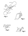
- La
figure 1 est une vue en perspective d'une prothèse implantée dans un doigt, conformément à l'invention. - La
figure 2 représente une vue en perspective schématique de la portion centrale d'une prothèse, conformément à l'invention. - La
figure 3 est une vue en perspective de la portion centrale de la prothèse symbolisant le mouvement de flexion, conformément à l'invention. - La
figure 4 est une vue en coupe schématique de la portion centrale de la prothèse, symbolisant la capacité de mouvement en latéralité de la prothèse, conformément à l'invention. - Les
figures 5 à 7 représentent des vues de profil schématiques de plusieurs variantes d'une prothèse, conforme à l'invention. - La
figure 8 est une vue en perspective d'une prothèse comportant une partie centrale ajourée. - Comme déjà évoqué, l'invention concerne une prothèse interphalangienne ou métacarpophalangienne comportant une portion centrale déformable (1) et deux parties d'ancrage (2) et (3) situées de part et d'autre de cette portion centrale. Avantageusement, la prothèse est réalisée dans un matériau comportant une grande élasticité tel qu'un alliage à mémoire de forme à base de titane et de nickel. L'alliage à mémoire de forme est sélectionné pour que le taux local de la déformation maximum soit très inférieur à la limite de fatigue, selon la courbe WHOLER.
- Tel que décrit à la
figure 1 , la prothèse est implantée entre deux phalanges (4,5), la partie d'ancrage (2) étant insérée dans la phalange (4), tandis que la seconde partie d'ancrage (3) est insérée dans la phalange (5). La portion centrale (1) comporte au moins deux volets articulés l'un par rapport à l'autre, et raccordés par des plis aptes à permettre au moins un mouvement de flexion. Les volets sont alors aptes à se déplacer à la manière d'un accordéon se rapprochant l'un de l'autre pour permettre une compression de l'articulation, et peuvent pivoter l'un par rapport à l'autre pour permettre la flexion / extension. - Tel que représenté schématiquement à la
figure 2 , les volets peuvent être formés par le pliage d'une bande selon deux directions, dans une certaine limite car des butées peuvent limiter le mouvement (par exemple en extension). - Tel que représenté schématiquement à la
figure 3 , la portion centrale (1) peut se déformer afin d'autoriser la flexion d'un doigt. Pour ce faire, chaque volet peut pivoter l'un par rapport à l'autre autour des plis qu'elle comporte. Cette géométrie particulière permet en outre de fournir une grande stabilité en compression de l'implant lorsque celui-ci est en position fléchie. - Tel que représenté schématiquement à la
figure 4 , la portion centrale permet de générer une mobilité en latéralité de l'articulation. La forme et l'épaisseur des volets permet alors d'ajuster les efforts pour permettre la flexion et également la plage de mouvement autorisée. Il suffit pour cela de faire varier la section de la bande utilisée pour les volets, la hauteur des volets et leur nombre et éventuellement, les butées. - A titre d'exemple, il a été réalisé des essais avec une partie centrale, l'une comportant cinq volets identiques, de section 0,17 mm, de hauteur 6,6 mm, de largeur 6,7 mm et de longueur 7mm. Avec cette géométrie, il a été mesuré la contrainte nécessaire à l'obtention de la déformation de la portion centrale dans une position à 90° en flexion, soit une charge de 120 g. La déformation interne est alors de 0,31 % dans ce cas précis.
- De plus, l'axe de rotation de la partie centrale (1) est mobile au cours de la flexion, de la même façon que celui d'une articulation saine. La position de la zone de liaison entre les parties d'ancrage (2, 3) et la portion centrale (1) permet alors de modifier le déplacement de l'axe de rotation lors de la flexion.
- Tel que représenté à la
figure 5 , les plis (6) situés dans la zone supérieure de la portion centrale (1) sont sensiblement identiques aux plis (7) situés dans la partie inférieure de la portion (1). - Selon un autre mode de réalisation tel que représenté à la
figure 6 , les plis (16) situés dans la partie supérieure de la portion (1) sont différents des plis (17) situés dans la partie inférieure de la portion centrale (1). - Tel que représenté à la
figure 7 , les plis sont disposés de manière symétrique par rapport à un plan contenant les axes des parties d'ancrage (2,3). Ainsi, les plis (26) se situent à la même distance de ce plan que les plis (27). - Il est également possible de rendre asymétriques les plis par rapport au plan contenant les axes des parties d'ancrage. De cette manière, il est possible de faciliter la flexion ou l'extension en déplaçant la hauteur de l'axe de rotation. Ceci peut être envisagé lorsque des ligaments sont endommagés, car un déplacement dorsal de l'axe de rotation facilite la flexion et un déplacement palmaire facilite l'extension.
- Tel que représenté à la
figure 8 , la portion centrale (1) comporte des volets ajourés. De cette manière, cela revient à disposer deux volets de très faible largeur, l'un à côté de l'autre. Il est bien entendu que l'invention ne se limite pas à cette unique variante et peut présenter une pluralité de volets disposés l'un par rapport à l'autre. - On observe également que la prothèse peut, dans une première variante, se présenter sous la forme d'un ensemble monobloc, les deux parties d'ancrage (2) et (3) et la portion centrale (1) étant solidaires.
- Dans une seconde variante, il est possible de rapporter la portion centrale (1) entre les deux parties d'ancrage (2) et (3) de façon à permettre le changement ultérieur de cette portion, par exemple lorsque la mobilité de l'articulation n'est plus adaptée ou plus simplement lorsque la portion centrale a perdu de son élasticité.
- Il ressort de ce qui précède que la prothèse conforme à l'invention présente de multiples avantages et notamment :
- elle permet de fournir une liaison pivot dont l'axe de rotation est mobile à la manière d'une articulation saine ;
- elle autorise une capacité de mouvement en latéralité ;
- elle est réalisée en un matériau qui n'est pas dangereux pour l'organisme, et qui permet une grande longévité de la prothèse grâce à l'élasticité du matériau ;
- elle permet une grande stabilité en compression lors de la flexion ;
- les plis permettent de diminuer la déformation locale et permettent de régler les butées de latéralité.
- Comme indiqué, l'invention trouve une application avantageuse dans le cadre de fractures interphalangiennes, métacarpophalangiennes, et métatarsophalangiennes.
Claims (9)
- Prothèse interphalangienne et/ou métacarpophalangienne comportant une portion centrale déformable (1) et deux parties d'ancrage (2) et (3) situées de part et d'autre de cette portion centrale (1), la portion centrale (1) comportant au moins deux volets articulés l'un par rapport à l'autre, en faisant office de plis aptes à permettre au moins un mouvement de flexion, caractérisée en ce que ladite prothèse est dans un alliage à mémoire de forme pour avoir une grande élasticité.
- Prothèse selon la revendication 1, caractérisée en ce que l'alliage à mémoire de forme comporte du titane et du nickel.
- Prothèse selon l'une quelconque des revendications 1 à 2, caractérisée en ce que chaque volet est apte à se déformer en torsion.
- Prothèse selon l'une quelconque des revendications 1 à 3, caractérisée en ce que les volets de la portion centrale (1) sont ajourés longitudinalement
- Prothèse selon l'une quelconque des revendications 1 à 4, caractérisée en ce que la section des volets est variable.
- Prothèse selon l'une quelconque des revendications 1 à 5, caractérisée en ce que les plis sont symétriques entre eux.
- Prothèse selon l'une quelconque des revendications 1 à 5, caractérisée en ce que les plis sont asymétriques entre eux.
- Prothèse selon l'une quelconque des revendications 1 à 7, caractérisée en ce que les plis sont disposés symétriquement par rapport aux parties d'ancrage.
- Prothèse selon l'une quelconque des revendications 1 à 7, caractérisée en ce que les plis sont disposés de manière décalée par rapport aux parties d'ancrage.
Applications Claiming Priority (2)
| Application Number | Priority Date | Filing Date | Title |
|---|---|---|---|
| FR0315635A FR2863867B1 (fr) | 2003-12-22 | 2003-12-22 | Prothese interphalangienne et/ou metacarpophalangienne |
| PCT/FR2004/050735 WO2005063149A1 (fr) | 2003-12-22 | 2004-12-20 | Prothese interphalangienne et/ou metacarpophalangienne |
Publications (2)
| Publication Number | Publication Date |
|---|---|
| EP1708653A1 EP1708653A1 (fr) | 2006-10-11 |
| EP1708653B1 true EP1708653B1 (fr) | 2009-09-30 |
Family
ID=34630560
Family Applications (1)
| Application Number | Title | Priority Date | Filing Date |
|---|---|---|---|
| EP04817623A Expired - Lifetime EP1708653B1 (fr) | 2003-12-22 | 2004-12-20 | Prothese interphalangienne et/ou metacarpophalangienne |
Country Status (5)
| Country | Link |
|---|---|
| EP (1) | EP1708653B1 (fr) |
| AT (1) | ATE444037T1 (fr) |
| DE (1) | DE602004023427D1 (fr) |
| FR (1) | FR2863867B1 (fr) |
| WO (1) | WO2005063149A1 (fr) |
Cited By (10)
| Publication number | Priority date | Publication date | Assignee | Title |
|---|---|---|---|---|
| US8945232B2 (en) | 2012-12-31 | 2015-02-03 | Wright Medical Technology, Inc. | Ball and socket implants for correction of hammer toes and claw toes |
| US9044287B2 (en) | 2010-06-02 | 2015-06-02 | Wright Medical Technology, Inc. | Hammer toe implant method |
| US9474561B2 (en) | 2013-11-19 | 2016-10-25 | Wright Medical Technology, Inc. | Two-wire technique for installing hammertoe implant |
| US9498273B2 (en) | 2010-06-02 | 2016-11-22 | Wright Medical Technology, Inc. | Orthopedic implant kit |
| US9498266B2 (en) | 2014-02-12 | 2016-11-22 | Wright Medical Technology, Inc. | Intramedullary implant, system, and method for inserting an implant into a bone |
| US9545274B2 (en) | 2014-02-12 | 2017-01-17 | Wright Medical Technology, Inc. | Intramedullary implant, system, and method for inserting an implant into a bone |
| US9603643B2 (en) | 2010-06-02 | 2017-03-28 | Wright Medical Technology, Inc. | Hammer toe implant with expansion portion for retrograde approach |
| US9808296B2 (en) | 2014-09-18 | 2017-11-07 | Wright Medical Technology, Inc. | Hammertoe implant and instrument |
| US10080597B2 (en) | 2014-12-19 | 2018-09-25 | Wright Medical Technology, Inc. | Intramedullary anchor for interphalangeal arthrodesis |
| US11660202B2 (en) | 2018-10-04 | 2023-05-30 | Medartis Ag | Joint arthroplasty device and method |
Families Citing this family (12)
| Publication number | Priority date | Publication date | Assignee | Title |
|---|---|---|---|---|
| FR2884406B1 (fr) | 2005-04-14 | 2008-10-17 | Memometal Technologies Soc Par | Dispositif d'osteosynthese intramedullaire de deux parties d'os, notamment de la main et/ou du pied |
| FR2913876B1 (fr) | 2007-03-20 | 2009-06-05 | Memometal Technologies Soc Par | Dispositif d'osteosynthese |
| FR2927529B1 (fr) * | 2008-02-14 | 2011-02-11 | Pfaifer Patrick | Prothese d'articulation pour articulation inter-phalangienne ou phalango-metacarpienne ou phalango-metatarsienne |
| FR2935601B1 (fr) | 2008-09-09 | 2010-10-01 | Memometal Technologies | Implant intramedullaire resorbable entre deux os ou deux fragments osseux |
| US8685024B2 (en) | 2010-04-14 | 2014-04-01 | Arrowhead Medical Device Technologies, Llc | Intramedullary fixation device and methods for bone fixation and stabilization |
| US10349987B2 (en) | 2010-04-14 | 2019-07-16 | Arrowhead Medical Device Technologies, Llc | Intramedullary fixation devices |
| US9724140B2 (en) | 2010-06-02 | 2017-08-08 | Wright Medical Technology, Inc. | Tapered, cylindrical cruciform hammer toe implant and method |
| EP2967687B1 (fr) | 2013-03-13 | 2019-01-09 | Arrowhead Medical Device Technologies LLC | Procédés et implants pour traiter l'orteil en marteau et d'autres déformités |
| US9452002B2 (en) | 2013-03-13 | 2016-09-27 | Arrowhead Medical Device Technologies, Llc | Hammertoe implant with enhanced gripping surfaces |
| US10582957B2 (en) | 2014-09-19 | 2020-03-10 | Crossroads Extremity Systems, Llc | Bone fixation implant and means of fixation |
| US9757168B2 (en) | 2015-03-03 | 2017-09-12 | Howmedica Osteonics Corp. | Orthopedic implant and methods of implanting and removing same |
| US10470807B2 (en) | 2016-06-03 | 2019-11-12 | Stryker European Holdings I, Llc | Intramedullary implant and method of use |
Family Cites Families (2)
| Publication number | Priority date | Publication date | Assignee | Title |
|---|---|---|---|---|
| FI101933B (fi) * | 1995-06-13 | 1998-09-30 | Biocon Oy | Nivelproteesi |
| US5824095A (en) * | 1996-04-26 | 1998-10-20 | E. I. Du Pont De Nemours And Company | Anatomically neutral joint |
-
2003
- 2003-12-22 FR FR0315635A patent/FR2863867B1/fr not_active Expired - Fee Related
-
2004
- 2004-12-20 AT AT04817623T patent/ATE444037T1/de not_active IP Right Cessation
- 2004-12-20 EP EP04817623A patent/EP1708653B1/fr not_active Expired - Lifetime
- 2004-12-20 DE DE602004023427T patent/DE602004023427D1/de not_active Expired - Fee Related
- 2004-12-20 WO PCT/FR2004/050735 patent/WO2005063149A1/fr not_active Ceased
Cited By (17)
| Publication number | Priority date | Publication date | Assignee | Title |
|---|---|---|---|---|
| US9949775B2 (en) | 2010-06-02 | 2018-04-24 | Wright Medical Technology, Inc. | Hammer toe implant with expansion portion for retrograde approach |
| US9044287B2 (en) | 2010-06-02 | 2015-06-02 | Wright Medical Technology, Inc. | Hammer toe implant method |
| US9498273B2 (en) | 2010-06-02 | 2016-11-22 | Wright Medical Technology, Inc. | Orthopedic implant kit |
| US10736676B2 (en) | 2010-06-02 | 2020-08-11 | Wright Medical Technology, Inc. | Orthopedic implant kit |
| US9603643B2 (en) | 2010-06-02 | 2017-03-28 | Wright Medical Technology, Inc. | Hammer toe implant with expansion portion for retrograde approach |
| US9877753B2 (en) | 2010-06-02 | 2018-01-30 | Wright Medical Technology, Inc. | Orthopedic implant kit |
| US8945232B2 (en) | 2012-12-31 | 2015-02-03 | Wright Medical Technology, Inc. | Ball and socket implants for correction of hammer toes and claw toes |
| US9504582B2 (en) | 2012-12-31 | 2016-11-29 | Wright Medical Technology, Inc. | Ball and socket implants for correction of hammer toes and claw toes |
| US10278828B2 (en) | 2012-12-31 | 2019-05-07 | Wright Medical Technology, Inc. | Ball and socket implants for correction of hammer toes and claw toes |
| US9474561B2 (en) | 2013-11-19 | 2016-10-25 | Wright Medical Technology, Inc. | Two-wire technique for installing hammertoe implant |
| US9675392B2 (en) | 2013-11-19 | 2017-06-13 | Wright Medical Technology, Inc. | Two-wire technique for installing hammertoe implant |
| US9498266B2 (en) | 2014-02-12 | 2016-11-22 | Wright Medical Technology, Inc. | Intramedullary implant, system, and method for inserting an implant into a bone |
| US9545274B2 (en) | 2014-02-12 | 2017-01-17 | Wright Medical Technology, Inc. | Intramedullary implant, system, and method for inserting an implant into a bone |
| US9808296B2 (en) | 2014-09-18 | 2017-11-07 | Wright Medical Technology, Inc. | Hammertoe implant and instrument |
| US10299840B2 (en) | 2014-09-18 | 2019-05-28 | Wright Medical Technology, Inc. | Hammertoe implant and instrument |
| US10080597B2 (en) | 2014-12-19 | 2018-09-25 | Wright Medical Technology, Inc. | Intramedullary anchor for interphalangeal arthrodesis |
| US11660202B2 (en) | 2018-10-04 | 2023-05-30 | Medartis Ag | Joint arthroplasty device and method |
Also Published As
| Publication number | Publication date |
|---|---|
| DE602004023427D1 (de) | 2009-11-12 |
| WO2005063149A1 (fr) | 2005-07-14 |
| EP1708653A1 (fr) | 2006-10-11 |
| ATE444037T1 (de) | 2009-10-15 |
| FR2863867A1 (fr) | 2005-06-24 |
| FR2863867B1 (fr) | 2007-05-04 |
Similar Documents
| Publication | Publication Date | Title |
|---|---|---|
| EP1708653A1 (fr) | Prothese interphalangienne et/ou metacarpophalangienne | |
| EP0646353B1 (fr) | Agrafe d'ostéosynthèse multi-branches à compression dynamique auto-rétentive | |
| EP0516567B1 (fr) | Dispositif de stabilisation intervertébrale à amortisseurs | |
| EP2385813B1 (fr) | Implant orthopedique pour arthroplastie digitale | |
| EP1139932B1 (fr) | Prothese de disque intervertebral a frottements reduits | |
| EP0310483B1 (fr) | Prothèse d'articulation métacarpo-phalangienne ou inter-phalangienne de doigts | |
| FR3058044A1 (fr) | Cage intersomatique expansible | |
| WO2010001010A1 (fr) | Prothese totale de genou | |
| FR2889438A1 (fr) | Implant intervertebral a double forme | |
| CA2354165A1 (fr) | Prothese de disque intervertebral a plots | |
| FR2642301A1 (fr) | Prothese composite particulierement destinee au remplacement du medaillon rotulien, des plateaux tibiaux, des cotyles ou toute autre articulation procurant un effet d'amortisseur | |
| EP1890655A1 (fr) | Dispositif apte a etre intercale entre deux vertebres consecutives | |
| EP2032084B1 (fr) | Prothese de disque intervertebral | |
| WO2008087291A2 (fr) | Prothèse de remplacement de nucléus ou de disque intervertébral | |
| EP1453443A1 (fr) | Implant trapezien ou trapezo-metacarpien | |
| FR2742043A1 (fr) | Prothese totale pour articulation phalangienne | |
| EP1112753B1 (fr) | Implant d'interposition mobile entre deux surfaces osseuses | |
| FR2852819A1 (fr) | Prothese totale postero-stabilisee du genou | |
| EP1696837B1 (fr) | Prothese de disque intervertebral | |
| EP1159939B1 (fr) | Prothèse totale de poignet | |
| CH645802A5 (en) | Endoprosthetic bone joint device | |
| EP4149376B1 (fr) | Dispositif implantable, notamment de type espaceur intervertébral | |
| EP0855885A1 (fr) | Prothese articulaire digitale a axe flottant | |
| EP1706076B1 (fr) | Prothese discale intervertebrale | |
| WO2008043906A2 (fr) | Ensemble de stabilisation intervertebrale |
Legal Events
| Date | Code | Title | Description |
|---|---|---|---|
| PUAI | Public reference made under article 153(3) epc to a published international application that has entered the european phase |
Free format text: ORIGINAL CODE: 0009012 |
|
| 17P | Request for examination filed |
Effective date: 20060720 |
|
| AK | Designated contracting states |
Kind code of ref document: A1 Designated state(s): AT BE BG CH CY CZ DE DK EE ES FI FR GB GR HU IE IS IT LI LT LU MC NL PL PT RO SE SI SK TR |
|
| DAX | Request for extension of the european patent (deleted) | ||
| GRAP | Despatch of communication of intention to grant a patent |
Free format text: ORIGINAL CODE: EPIDOSNIGR1 |
|
| GRAS | Grant fee paid |
Free format text: ORIGINAL CODE: EPIDOSNIGR3 |
|
| 17Q | First examination report despatched |
Effective date: 20090310 |
|
| GRAA | (expected) grant |
Free format text: ORIGINAL CODE: 0009210 |
|
| AK | Designated contracting states |
Kind code of ref document: B1 Designated state(s): AT BE BG CH CY CZ DE DK EE ES FI FR GB GR HU IE IS IT LI LT LU MC NL PL PT RO SE SI SK TR |
|
| REG | Reference to a national code |
Ref country code: GB Ref legal event code: FG4D Free format text: NOT ENGLISH Ref country code: CH Ref legal event code: EP |
|
| REG | Reference to a national code |
Ref country code: IE Ref legal event code: FG4D |
|
| REF | Corresponds to: |
Ref document number: 602004023427 Country of ref document: DE Date of ref document: 20091112 Kind code of ref document: P |
|
| PG25 | Lapsed in a contracting state [announced via postgrant information from national office to epo] |
Ref country code: FI Free format text: LAPSE BECAUSE OF FAILURE TO SUBMIT A TRANSLATION OF THE DESCRIPTION OR TO PAY THE FEE WITHIN THE PRESCRIBED TIME-LIMIT Effective date: 20090930 Ref country code: SE Free format text: LAPSE BECAUSE OF FAILURE TO SUBMIT A TRANSLATION OF THE DESCRIPTION OR TO PAY THE FEE WITHIN THE PRESCRIBED TIME-LIMIT Effective date: 20090930 Ref country code: LT Free format text: LAPSE BECAUSE OF FAILURE TO SUBMIT A TRANSLATION OF THE DESCRIPTION OR TO PAY THE FEE WITHIN THE PRESCRIBED TIME-LIMIT Effective date: 20090930 |
|
| LTIE | Lt: invalidation of european patent or patent extension |
Effective date: 20090930 |
|
| PG25 | Lapsed in a contracting state [announced via postgrant information from national office to epo] |
Ref country code: PL Free format text: LAPSE BECAUSE OF FAILURE TO SUBMIT A TRANSLATION OF THE DESCRIPTION OR TO PAY THE FEE WITHIN THE PRESCRIBED TIME-LIMIT Effective date: 20090930 Ref country code: SI Free format text: LAPSE BECAUSE OF FAILURE TO SUBMIT A TRANSLATION OF THE DESCRIPTION OR TO PAY THE FEE WITHIN THE PRESCRIBED TIME-LIMIT Effective date: 20090930 |
|
| NLV1 | Nl: lapsed or annulled due to failure to fulfill the requirements of art. 29p and 29m of the patents act | ||
| PG25 | Lapsed in a contracting state [announced via postgrant information from national office to epo] |
Ref country code: RO Free format text: LAPSE BECAUSE OF FAILURE TO SUBMIT A TRANSLATION OF THE DESCRIPTION OR TO PAY THE FEE WITHIN THE PRESCRIBED TIME-LIMIT Effective date: 20090930 Ref country code: CZ Free format text: LAPSE BECAUSE OF FAILURE TO SUBMIT A TRANSLATION OF THE DESCRIPTION OR TO PAY THE FEE WITHIN THE PRESCRIBED TIME-LIMIT Effective date: 20090930 Ref country code: ES Free format text: LAPSE BECAUSE OF FAILURE TO SUBMIT A TRANSLATION OF THE DESCRIPTION OR TO PAY THE FEE WITHIN THE PRESCRIBED TIME-LIMIT Effective date: 20100110 Ref country code: EE Free format text: LAPSE BECAUSE OF FAILURE TO SUBMIT A TRANSLATION OF THE DESCRIPTION OR TO PAY THE FEE WITHIN THE PRESCRIBED TIME-LIMIT Effective date: 20090930 Ref country code: IS Free format text: LAPSE BECAUSE OF FAILURE TO SUBMIT A TRANSLATION OF THE DESCRIPTION OR TO PAY THE FEE WITHIN THE PRESCRIBED TIME-LIMIT Effective date: 20100130 Ref country code: PT Free format text: LAPSE BECAUSE OF FAILURE TO SUBMIT A TRANSLATION OF THE DESCRIPTION OR TO PAY THE FEE WITHIN THE PRESCRIBED TIME-LIMIT Effective date: 20100201 |
|
| REG | Reference to a national code |
Ref country code: IE Ref legal event code: FD4D |
|
| PG25 | Lapsed in a contracting state [announced via postgrant information from national office to epo] |
Ref country code: CY Free format text: LAPSE BECAUSE OF FAILURE TO SUBMIT A TRANSLATION OF THE DESCRIPTION OR TO PAY THE FEE WITHIN THE PRESCRIBED TIME-LIMIT Effective date: 20090930 Ref country code: SK Free format text: LAPSE BECAUSE OF FAILURE TO SUBMIT A TRANSLATION OF THE DESCRIPTION OR TO PAY THE FEE WITHIN THE PRESCRIBED TIME-LIMIT Effective date: 20090930 |
|
| BERE | Be: lapsed |
Owner name: MEMOMETAL TECHNOLOGIES Effective date: 20091231 |
|
| PG25 | Lapsed in a contracting state [announced via postgrant information from national office to epo] |
Ref country code: NL Free format text: LAPSE BECAUSE OF FAILURE TO SUBMIT A TRANSLATION OF THE DESCRIPTION OR TO PAY THE FEE WITHIN THE PRESCRIBED TIME-LIMIT Effective date: 20090930 Ref country code: DK Free format text: LAPSE BECAUSE OF FAILURE TO SUBMIT A TRANSLATION OF THE DESCRIPTION OR TO PAY THE FEE WITHIN THE PRESCRIBED TIME-LIMIT Effective date: 20090930 Ref country code: IE Free format text: LAPSE BECAUSE OF FAILURE TO SUBMIT A TRANSLATION OF THE DESCRIPTION OR TO PAY THE FEE WITHIN THE PRESCRIBED TIME-LIMIT Effective date: 20090930 Ref country code: MC Free format text: LAPSE BECAUSE OF NON-PAYMENT OF DUE FEES Effective date: 20100701 |
|
| REG | Reference to a national code |
Ref country code: CH Ref legal event code: PL |
|
| PLBE | No opposition filed within time limit |
Free format text: ORIGINAL CODE: 0009261 |
|
| STAA | Information on the status of an ep patent application or granted ep patent |
Free format text: STATUS: NO OPPOSITION FILED WITHIN TIME LIMIT |
|
| GBPC | Gb: european patent ceased through non-payment of renewal fee |
Effective date: 20091230 |
|
| 26N | No opposition filed |
Effective date: 20100701 |
|
| REG | Reference to a national code |
Ref country code: FR Ref legal event code: ST Effective date: 20100831 |
|
| PG25 | Lapsed in a contracting state [announced via postgrant information from national office to epo] |
Ref country code: FR Free format text: LAPSE BECAUSE OF NON-PAYMENT OF DUE FEES Effective date: 20091231 Ref country code: CH Free format text: LAPSE BECAUSE OF NON-PAYMENT OF DUE FEES Effective date: 20091231 Ref country code: LI Free format text: LAPSE BECAUSE OF NON-PAYMENT OF DUE FEES Effective date: 20091231 Ref country code: BE Free format text: LAPSE BECAUSE OF NON-PAYMENT OF DUE FEES Effective date: 20091231 Ref country code: GR Free format text: LAPSE BECAUSE OF FAILURE TO SUBMIT A TRANSLATION OF THE DESCRIPTION OR TO PAY THE FEE WITHIN THE PRESCRIBED TIME-LIMIT Effective date: 20091231 |
|
| PG25 | Lapsed in a contracting state [announced via postgrant information from national office to epo] |
Ref country code: DE Free format text: LAPSE BECAUSE OF NON-PAYMENT OF DUE FEES Effective date: 20100701 |
|
| PG25 | Lapsed in a contracting state [announced via postgrant information from national office to epo] |
Ref country code: GB Free format text: LAPSE BECAUSE OF NON-PAYMENT OF DUE FEES Effective date: 20091230 |
|
| PG25 | Lapsed in a contracting state [announced via postgrant information from national office to epo] |
Ref country code: IT Free format text: LAPSE BECAUSE OF FAILURE TO SUBMIT A TRANSLATION OF THE DESCRIPTION OR TO PAY THE FEE WITHIN THE PRESCRIBED TIME-LIMIT Effective date: 20090930 Ref country code: BG Free format text: LAPSE BECAUSE OF FAILURE TO SUBMIT A TRANSLATION OF THE DESCRIPTION OR TO PAY THE FEE WITHIN THE PRESCRIBED TIME-LIMIT Effective date: 20091231 |
|
| PG25 | Lapsed in a contracting state [announced via postgrant information from national office to epo] |
Ref country code: LU Free format text: LAPSE BECAUSE OF NON-PAYMENT OF DUE FEES Effective date: 20091220 |
|
| PG25 | Lapsed in a contracting state [announced via postgrant information from national office to epo] |
Ref country code: AT Free format text: LAPSE BECAUSE OF NON-PAYMENT OF DUE FEES Effective date: 20091220 |
|
| PG25 | Lapsed in a contracting state [announced via postgrant information from national office to epo] |
Ref country code: HU Free format text: LAPSE BECAUSE OF FAILURE TO SUBMIT A TRANSLATION OF THE DESCRIPTION OR TO PAY THE FEE WITHIN THE PRESCRIBED TIME-LIMIT Effective date: 20100401 |
|
| PG25 | Lapsed in a contracting state [announced via postgrant information from national office to epo] |
Ref country code: TR Free format text: LAPSE BECAUSE OF FAILURE TO SUBMIT A TRANSLATION OF THE DESCRIPTION OR TO PAY THE FEE WITHIN THE PRESCRIBED TIME-LIMIT Effective date: 20090930 |