EP1708445A1 - Kommunikationsvorrichtung und Feststellungsmethode für logische Verbindung Anomalie - Google Patents
Kommunikationsvorrichtung und Feststellungsmethode für logische Verbindung Anomalie Download PDFInfo
- Publication number
- EP1708445A1 EP1708445A1 EP20050014022 EP05014022A EP1708445A1 EP 1708445 A1 EP1708445 A1 EP 1708445A1 EP 20050014022 EP20050014022 EP 20050014022 EP 05014022 A EP05014022 A EP 05014022A EP 1708445 A1 EP1708445 A1 EP 1708445A1
- Authority
- EP
- European Patent Office
- Prior art keywords
- data
- communication device
- association
- transmission
- sctp
- Prior art date
- Legal status (The legal status is an assumption and is not a legal conclusion. Google has not performed a legal analysis and makes no representation as to the accuracy of the status listed.)
- Withdrawn
Links
Images


Classifications
-
- H—ELECTRICITY
- H04—ELECTRIC COMMUNICATION TECHNIQUE
- H04L—TRANSMISSION OF DIGITAL INFORMATION, e.g. TELEGRAPHIC COMMUNICATION
- H04L1/00—Arrangements for detecting or preventing errors in the information received
- H04L1/12—Arrangements for detecting or preventing errors in the information received by using return channel
- H04L1/16—Arrangements for detecting or preventing errors in the information received by using return channel in which the return channel carries supervisory signals, e.g. repetition request signals
- H04L1/18—Automatic repetition systems, e.g. Van Duuren systems
- H04L1/1829—Arrangements specially adapted for the receiver end
-
- H—ELECTRICITY
- H04—ELECTRIC COMMUNICATION TECHNIQUE
- H04L—TRANSMISSION OF DIGITAL INFORMATION, e.g. TELEGRAPHIC COMMUNICATION
- H04L1/00—Arrangements for detecting or preventing errors in the information received
- H04L1/20—Arrangements for detecting or preventing errors in the information received using signal quality detector
-
- H—ELECTRICITY
- H04—ELECTRIC COMMUNICATION TECHNIQUE
- H04L—TRANSMISSION OF DIGITAL INFORMATION, e.g. TELEGRAPHIC COMMUNICATION
- H04L69/00—Network arrangements, protocols or services independent of the application payload and not provided for in the other groups of this subclass
- H04L69/14—Multichannel or multilink protocols
-
- H—ELECTRICITY
- H04—ELECTRIC COMMUNICATION TECHNIQUE
- H04L—TRANSMISSION OF DIGITAL INFORMATION, e.g. TELEGRAPHIC COMMUNICATION
- H04L69/00—Network arrangements, protocols or services independent of the application payload and not provided for in the other groups of this subclass
- H04L69/30—Definitions, standards or architectural aspects of layered protocol stacks
- H04L69/32—Architecture of open systems interconnection [OSI] 7-layer type protocol stacks, e.g. the interfaces between the data link level and the physical level
- H04L69/322—Intralayer communication protocols among peer entities or protocol data unit [PDU] definitions
- H04L69/326—Intralayer communication protocols among peer entities or protocol data unit [PDU] definitions in the transport layer [OSI layer 4]
-
- H—ELECTRICITY
- H04—ELECTRIC COMMUNICATION TECHNIQUE
- H04L—TRANSMISSION OF DIGITAL INFORMATION, e.g. TELEGRAPHIC COMMUNICATION
- H04L69/00—Network arrangements, protocols or services independent of the application payload and not provided for in the other groups of this subclass
- H04L69/40—Network arrangements, protocols or services independent of the application payload and not provided for in the other groups of this subclass for recovering from a failure of a protocol instance or entity, e.g. service redundancy protocols, protocol state redundancy or protocol service redirection
Definitions
- the present invention relates to a communication device that transmits and receives data by use of a logical link.
- SCTP Stream Control Transmission Protocol
- PSTN public switched telephone network
- IP Internet Protocol
- SCTP is a transport layer protocol that supports multi-homing and enables highly reliable data transmission over the IP layer, and is designed so as to be capable of dealing with DOS attacks (Denial of Service Attacks) etc. occurred when setting an association.
- SCTP is capable of securely transmitting the signals from PSTN even over the IP network having low reliability.
- terminals e.g., a server and a client or the like
- endpoints e.g., a server and a client or the like
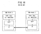
- FIG. 16 shows an example of a protocol stack that supports SCTP.
- SCTP employs IP as a network protocol.
- SCTP is utilized as a transport protocol by M3UA (MTP3 User Adaptation) etc. defined as an adaptation module for adapting the PSTN protocol to the IP network.
- M3UA MTP3 User Adaptation
- FIG. 17 shows an image of the multi-homing and SCTP associations.
- SCTP a logical connection between the endpoints is termed an Association.
- Association Approximately, four billion and three hundred million (2 32 ⁇ 1) associations can be set between the endpoints, wherein every association is identified by use of tags (TAG).
- the endpoint is assigned a plurality of IP addresses, whereby a communication path between the endpoints can be multiplexed.
- a single association is established between an endpoint A and an endpoint Z.
- the endpoint A is assigned three pieces of IP addresses (which are IP addresses A, B and C shown in FIG. 17), and the endpoint Z is assigned two pieces of IP addresses (which are IP addresses X and Y shown in FIG. 17), thereby multiplexing the path in the association.
- the communications can continue through other preset communication paths. It is therefore possible to enhance the reliability of the data transmission.
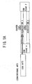
- FIG. 18 is a diagram showing how the multi-homing-unused SCTP association is established.
- associations 1 and 2 shown in FIG. 18 two lines of multi-homing-unused associations (associations 1 and 2 shown in FIG. 18) are established between the endpoint A and the endpoint Z.
- Routers (routers 221 and 222 shown in FIG. 18) can be interposed in the paths within the respective associations.
- FIG. 19 shows how the communication abnormality occurs in the association 1 in a connecting environment shown in FIG. 17. If the abnormality occurs in the association 1 when a message is transmitted to the endpoint Z from the endpoint A, the endpoint A detects that the transmitted message does not yet reach. From this detection, the abnormality in the association 1 is detected. The endpoint A detects unreachableness of the message when an SCTP-based retransmission timer expires.
- FIG. 20 illustrates how the SCTP association using the multi-homing is established.
- two lines of SCTP associations (the associations 1 and 2 shown in FIG. 20) each using the multi-homing are established between the endpoint A and the endpoint Z.
- each of the associations 1 and 2 uses the multi-homing, wherein two paths are extended within each of the associations (the association 1 contains the paths A and B, and the association 2 contains the paths C and D). Note that when the plurality of paths .are extended within the association, one of those paths is determined as a primary path (the primary paths shown in FIG. 20 are the paths A and C).
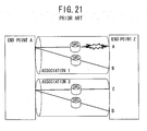
- FIG. 21 shows how the abnormality occurs in the path A within the association 1 in the connecting environment shown in FIG. 20. If the abnormality occurs in the path A of the association 1 when the message is transmitted to the endpoint Z from the endpoint A, the endpoint A detects that the transmitted message does not yet reach. From this detection, the abnormality in the path A of the association 1 is detected. The endpoint A detects the unreachableness of the message when the SCTP retransmission timer expires.
- FIG. 22 is a diagram showing an operating sequence of each endpoint when the communication abnormality occurs.
- the endpoint A In the case that the data are sent from the endpoint A via a router to the endpoint Z, when the data normally reach the endpoint Z, an S-ACK chunk is sent back from the endpoint Z.
- the "chunk" is a format unit of a SCTP message stream. If the communication abnormality occurs, however, the S-ACK chunk is not sent back from the endpoint Z, therefore, the endpoint A is unable to acquire acknowledgement that the transmission data reach. Such being the case, the endpoint A retransmits the transmission data a specified number of times.
- the endpoint A monitors a specified retransmission timer (T3-rtx timer shown in FIG. 22), and detects the abnormality in the path employed for transmitting the data from the expiration of the retransmission timer.
- the endpoint A which has detected the abnormality, notifies the endpoint Z of this communication abnormality by using other association or path.
- documents of the conventional art related to the present invention of the application are those disclosed as follows.
- the conventional art documents are " TOKUKAI 2001-186171 ", “ TOKUKAIHEI 06 -14056 “, “ TOKUKAIHEI 06 -53982 “, and “ R. Stewart , Q. Xie, et al., Stream Control Transmission Protocol” , Request for Comments: 2960 ".
- the abnormality detection method In the abnormality detection method according to this conventional art, however, it takes a long period of time till the endpoint detects a fault in the association or a fault in the path within the association. This is because the abnormality is not detected till a retransmission process (which involves the retransmission and the expiration of the retransmission timer in the endpoint A shown in FIG. 22) specified in the endpoint is completed.
- a real-time application using SCTP in the conventional art expends much time for abnormality detection control in the case where the communication abnormality occurs, and there is a possibility that a service can not be provided exactly.
- a great number of retrying operations based on the application are brought about at an abnormal time, resulting in a possibility of causing a decrease in traffic efficiency of the network as a whole.
- the object of the present invention is to provide a communication device capable of providing a highly reliable service by detecting communication abnormality at a high speed.
- the present invention adopts the following configurations in order to solve the problems described above.
- the present invention is a communication device comprising a link configuring unit configuring a plurality of logical links between the communication device itself and a opposite communication device, a segmenting unit segmenting transmission data in a way that associates the segmented data to each of the plurality of logical links, and a transmission unit transmitting the segmented data via one logical link associated with this segmented data.
- the present invention is a communication device comprising a link configuring unit configuring a plurality of logical links between the communication device itself and a opposite communication device, a segmenting unit for segmenting transmission data in a way that associates the segmented data to each of the plurality of logical links, a transmission unit transmitting the segmented data via the logical link associated with this segmented data, a receiving unit receiving the data via each of the plurality of logical links, and an abnormality detection unit judging, within a predetermined period of time since the data were received via any one of the plurality of logical links, if the data are not received via at least one of the remaining logical links, at least one logical link to be an abnormal logical link.
- the communication device when the communication device according to the present invention transmits the data, the data are segmented corresponding to the logical links established between the communication device itself and the communication device serving as the transmission destination, wherein the data are transmitted simultaneously via the respective logical links.
- the receiving-side communication device if the logical links established between the self-device and the communication device as a transmission source contain even one logical link via which the data are not received, this link is judged to be an abnormal logical link.
- the receiving-side communication device if there exists even one logical link via which the data are not received, it is judged that there is the abnormal logical link. Namely, the judgment about the abnormal logical link involves judging whether the data are received via all the logical links or not.
- the present invention it is possible to promptly detect the abnormality in the logical link by the receiving-side communication device without waiting for the transmitting-side communication device to detect the transmission abnormality.
- the communication device when segmenting the data, assigns a transmission number to every segmented data, and transmits the segmented data together with the transmission number assigned to every segmented data. Further, the communication device according to the present invention synthesizes the data received via every logical link, corresponding to the transmission number received together with this data.
- the transmitting-side communication device assigns the transmission number to every segmented data, and transmits the segmented data together with the transmission number.
- the receiving-side communication device synthesizes the received data in sequence of the transmission number, whereby the received data can be restored into the original data.
- a communication device further comprises a storage unit storing information about the logical link judged to be the abnormal logical link, wherein if the storage unit contains information about the abnormal logical link when requested to transmit the data, un-segmented data are transmitted via the logical link other than the abnormal logical link.
- the data can be normally transmitted.
- the present invention may be a program for actualizing any one of the functions given above. Further, the present invention may also be a readable-by-computer storage medium stored with such a program.
- the communication device capable of providing the highly reliable service by detecting the communication abnormality at the high speed.
- a communication device for carrying out the present invention, will hereinafter be explained with reference to the drawings.
- a configuration of the embodiment is an exemplification, and the present invention is not limited to the configuration of the embodiment.
- the embodiment, which will hereinafter be discussed, will exemplify an SCTP (Stream Control Transmission Protocol) communication device, however, the present invention is not limited to SCTP communications and relates to a communication device aiming at all of protocols enabling logical connections to be established.
- SCTP Stream Control Transmission Protocol
- FIGS. 1A and 1B are explanatory diagrams of the outline of the functions of the communication device in the embodiment.
- FIG. 1A shows SCTP communications in a conventional communication device
- FIG. 1B shows the SCTP communications in the communication device according to the embodiment.
- two lines of associations are established between an endpoint A and an endpoint Z each Serving as an SCTP communication device.
- association 1 when transmitting 1000-byte data to the endpoint Z from the endpoint A, one (association 1) of the associations established therebetween is employed, whereby the 1000-byte data are thus transmitted. Then, if the abnormality occurs in the association 1 used for the communications, the endpoint A on the transmitting side detects the abnormality by the SCTP retransmission process. Thereafter, the endpoint A retransmits the data, which could not be transmitted last time, by use of the other association 2 where the abnormality does not occur.
- the transmission data when transmitting the data to the endpoint Z from the endpoint A, the transmission data are segmented corresponding to the number of the associations established therebetween and thus transmitted via the respective associations.
- the 1000-byte data when there are the 1000-byte transmission data, the 1000-byte data are segmented by 500 bytes, wherein the 500-byte data are transmitted via the association 1 and another 500-byte data are transmitted via the association 2, simultaneously.
- the receiving-side communication device when receiving the data via the associations 1 and 2, restores the data by reassembling these sets of data received.
- the communication device on the receiving side detects the communication abnormality in the association.
- a contrivance is that the communication device in the embodiment, as the data receiving-side device detects the abnormality in the association when the abnormality occurs in the association, reduces abnormality detection time.
- FIG. 2 is a diagram showing the SCTP message format.
- An SCTP packet consists of, as shown in FIG. 2, one SCTP common header and a plurality of chunks (chunk #n). The chunks contained in the SCTP packet are multiplexed down to a size of Path-MTU (Maximum Transmission Unit).
- Path-MTU Maximum Transmission Unit
- FIG. 3 shows a format of the SCTP common header of the SCTP message.
- the SCTP common header contains the following information.
- FIG. 4 shows a message format of the chunk that is contained in the SCTP packet.
- the chunk contains a chunk type, a chunk flag, a chunk length and a chunk value.
- the chunk contains control information or user data, corresponding to a data type set in the chunk type. Then, actual pieces of information, which should be transferred in the chunks, are set as chunk values.
- FIG. 5 shows a relative table between the chunk type and the data type.
- the chunk type also indicates a chunk processing method in the receiving-side communication device receiving the chunk.
- FIG. 6 is a relative table between the data in the chunk type and a process corresponding to this data in the receiving-side communication device. The endpoint, when receiving the chunk including the chunk type unknown to the endpoint itself, judges from the most significant 2-bits of the chunk type whether the chunk must be processed or not.
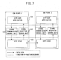
- FIG. 7 shows that the two communication devices (the endpoints A and Z) according to the embodiment (which will hereinafter be called the communication devices or the endpoints A and Z) are connected in a communicable state.
- the communication device is constructed of a CPU (Central Processing Unit), a memory, an I/O interface, etc., and the CPU executes programs stored on the memory, thereby actualizing respective functions shown in FIG. 7.
- CPU Central Processing Unit
- the communication device may be, for instance, a personal computer and may also be a gateway device or a router that connects a PSTN (Public Switched Telephone Network) to an IP (Internet Protocol) network, i.e., the communication device having the functional configuration shown in FIG. 7 suffices.
- a connecting form between the respective communication devices according to the embodiment is not particularly limited and may be a connecting form suited to a protocol stack enabling actualization of the SCTP communications.
- the connecting form may be such that the communication devices are connected over the physical layer such as 10BASE-T/2/5, 100BASE-T, etc..
- communication devices may be wirelessly connected without being limited to the wired physical layer.
- the communication device is constructed of an SCTP stack 101 (corresponding to a link configuring unit and a receiving unit according to the present invention), a signal reception control unit 102 (corresponding to an abnormality detection unit and a synthesizing unit according to the present invention), a signal transmission control unit 103 (corresponding to a segmenting unit and a transmitting unit according to the present invention), an SCTP-USER application 104 and an association information table (corresponding to a storage unit according to the present invention).
- the communication device actualizes the functions of the present invention by providing the signal reception control unit 102 and the signal transmission control unit 103 between the SCTP stack 101 and the SCTP-USER application 104 without altering SCTP itself defined in RFC2960 etc.
- the functional units will be individually described as follows.
- the SCTP stack 101 is a protocol stack that supports SCTP defined in RFC2960 etc.. Namely, the SCTP stack 101 supports SCTP as a transport layer and supports IP as a network layer. In the SCTP stack 101, there is no limit with respect to protocols of the lower-order layers (the data link layer and the physical layer) than the network layer as described above.
- the SCTP-USER application 104 is an application for actualizing the variety of functions through the SCTP communications.
- the SCTP-USER application 104 when the communication device is the gateway device that connects the PSTN to the IP network, may also be M3UA (MTP3 User Adaptation) etc. as an adaptation module for adapting the PSTN protocol to the IP network.
- M3UA MTP3 User Adaptation
- the association information table is, though not illustrated in FIG. 7, a table, stored on the memory, to which the signal transmission control unit 103 and the signal reception control unit 102 refer.
- FIG. 8 shows the association information table of the associations between the endpoint A and the endpoint Z.
- the association information table is retained by both of the transmitting-side communication device and the receiving-side communication device.
- the association information table is, as shown in FIG. 8, stored with pieces of information about an association number and an association communication state on an association-by-association-basis.
- a Tag value in the SCTP common header is set in the association number. Further, a total number of associations established in the communication devices is retained therein.
- association information table When establishing the association, a record about this association is created in the association information table.
- the signal reception control unit 102 and the signal transmission control unit 103 are notified of Tag information about the association established by the SCTP stack 101, and the association information table is generated based on the notified information.
- the embodiment exemplifies only the association information table of the associations between the endpoint A and the endpoint Z, however, the association information about the associations between other endpoints are similarly retained.
- the table may be prepared for every communication partner endpoint, and the association information may also be managed by one table in a way that prepares a field for storing a port number etc. for identifying the partner endpoint.
- the signal transmission control unit 103 segments the data transmitted from the SCTP-USER application 104 on the association-by-association basis, and instructs the SCTP stack 101 to simultaneously transmit the segmented data by use of the respective associations.
- the information on the association is extracted from the association information table.
- the data segmentation by the signal transmission control unit 103 does not particularly limit the segmentation method.
- the conceivable segmentation methods are, for instance, an equal segmentation for segmenting the data in a transmission data size that is equal throughout all the associations, a variable segmentation that determines the transmission data size depending on a transmission speed of each association, and so on.
- the signal transmission control unit 103 retains the pre-segmentation data till a normal S-ACK chunk is sent back from the partner communication device.
- This scheme is that if the abnormality occurs in a certain association, the data are transmitted via other normal associations without the segmentation thereof.
- the signal transmission control unit 103 which has received a data transmission request afresh, refers to the association information table and, if there is even one single association exhibiting an abnormal communication state, transmits the data in the non-segmented state by use of the normal associations.
- the signal reception control unit 102 restores the data sent from the partner communication device and transfers to the SCTP-USER application 104.
- the signal reception control unit 102 detects, as a restoration failure in the data restoration becomes a trigger, the communication abnormality in the association (which will hereinafter be termed association abnormality).
- association abnormality the communication abnormality in the association
- the signal reception control unit 102 if the data are not received via all the associations in the case of receiving the data any one of the established associations', conceives this as the restoration failure.
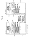
- FIG. 9 is a diagram illustrating an image of the data transmission between the communication devices.
- FIG. 10 shows an example of settings in the association information table in the embodiment.
- FIG. 9 illustrates the two communication devices (the endpoints A and B) in the embodiment shown in FIG. 7.
- the two associations (the associations 1 and 2) are established between the endpoint A and the endpoint B.
- the operation of the communication device will be described as below.
- the signal transmission control unit 103 when requesting a 1000-byte data transmission from the SCTP-USER application 104 ((1) shown in FIG. 9), refers to the association information table.
- the association information table has the settings as shown in FIG. 10 and is retained by both of the endpoints A and Z. Namely, records about the two associations are set in the association information table, wherein the respective communication information is set as being normal.
- the signal transmission control unit 103 transfers the segmented data together with the association numbers and the transmission numbers, which are each employed for the transmission, to the SCTP stack 101 ((2) shown in FIG. 9). Based on these data and information, the SCTP stack 101 generates an SCTP packet. SCTP message formats generated at this time are the formats shown in FIGS: 2 through 4.
- the segmented data itself is set as a chunk value (which is the chunk value shown in FIG. 4), and the transmission number assigned to every segmented data as a chunk flag (which is the chunk flaq shown in FIG. 4) is set.
- the SCTP stack 101 transmits the 500-byte data assigned the transmission number "1" via the association 1 and another 500-byte data assigned the transmission number "2" via the association 2, simultaneously ((3) shown in FIG. 9).
- the receiving-side endpoint Z receives the SCTP packet containing the segmented data via the associations 1 and 2.
- An SCTP stack 111 extracts the segmented data, the transmission numbers and Tag from the received SCTP packet.
- the SCTP stack 111 transfers these extracted data to the signal reception control unit 113 ((4) shown in FIG. 9).
- the signal reception control unit 113 searches through the self-retained association information table by use of the Tag value as a key, and thus confirms that the data are received via all the relevant associations. Thereafter, the signal reception control unit 113 reassembles the segmented data in sequence of the transmission numbers, thereby restoring the transmission data ((5) shown in FIG. 9).
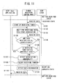
- FIG. 11 shows an operation sequence of the communication device at the normal time in the embodiment.
- the communication device stays in the [not-yet-received state] when the communication device is in a data not-yet-received state and all the associations are normal. Thereafter, when the data are received via any one of the associations, the communication device transits to a [received state].
- the received data are transferred to the signal reception control unit from the SCTP stack (S1101).
- the signal reception control unit starts up a receiving timer (S1102). This receiving timer is a waiting timer of waiting time till the data are received from all the associations.
- the signal reception control unit waits for the data to be received from the association other than the association through which the previous data have been received (S1103).
- the signal reception control unit judges whether the data are received via all the associations or not (S1105). If the data are received via all the associations (S1105; YES), the signal reception control unit clears the receiving timer (S1108), and there comes a [reception complete state]. When transiting to the [reception complete state], the signal reception control unit restores the received data (S1109), and transfers the restored data to the SCTP-USER application (S1110).
- the signal reception control unit conceives that the abnormality occurs in the association via which the data are not received (S1107).
- the communication device transits to an [abnormal association detected state]. An operation from this state onward will be discussed later on in an item of the operation at an association abnormal time.
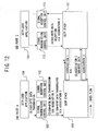
- FIG. 12 is a diagram showing an image of the data transmission between the communication devices in the case where the association abnormality occurs.
- FIG. 13 shows an example of the settings in the association information table at the association abnormal time.
- the endpoint A on the transmitting side transmits the 500-byte data assigned the transmission number "1" via the association 1 and another 500-byte data assigned the transmission number "2" via the association 2, respectively.
- FIG. 12 shows a case in which the abnormality occurs in the association 1 in that instance, and the endpoint Z is unable to receive the data. Namely, the signal reception control unit 113 of the endpoint Z receives the data assigned the transmission number "2" via the association 2 but does not receive the data via the association 1.
- the signal reception control unit 113 when all the associations are recognized to be normal, expects the data to be always received via all the associations. Therefore, when coming to a state where the data are received via only the association 2, the signal reception control unit 113 judges, as the data can not be normally restored, that some sort of abnormality occurs in the association 1.
- the operation that the signal reception control unit 113 judges the association to be abnormal is conducted by use of the receiving timer and an abnormality detection threshold value.
- the signal reception control unit 113 when receiving the data via any one of the associations, starts up the receiving timer. Thereafter, the signal reception control unit 113 judges all the associations to be normal in the case of receiving the data via all other associations till the receiving timer comes to the abnormality detection threshold value. While on the other hand, if there is the association via which the data can not be received till the receiving timer comes to the abnormality detection threshold value, the signal reception control unit 113 judges this association to be abnormal.
- the signal reception control unit 113 updates the association state in the association information table with the result of this judgment.
- FIG. 13 shows the association information table updated by the signal reception control unit 113 in that case. As shown in FIG. 13, in that case, the state of the association 1 becomes "abnormal".
- the endpoint A transmitting the segmented data detects the communication abnormality in the association 1.
- the endpoint A detects this communication abnormality by use of the retransmission timer, a retransmission count, etc. in the form adapted to the SCTP specifications described above.
- the signal transmission control unit 103 notified of the association abnormality updates, based on this information, the association state in the self-retained association information table.
- the signal transmission control unit 112 executes the transmission process irrespective of the state of the signal reception control unit 113. This intends to enable the communication partner side (the endpoint A) to recognize the association abnormality by transmitting the data even in a state where there is concern about the occurrence of the abnormality in the association 1.
- the endpoints A and Z detecting the abnormality in.the association 1 do not hereafter employ the association 1 for the data transmission. Namely, if the abnormality occurs in even one of the associations, the signal transmission control unit 103, without segmenting hereafter the data, transmits the data by using the normal associations in the same way as conventionally done by SCTP. Thereafter, the signal transmission control unit 103 of the endpoint A and the signal reception control unit 113 of the endpoint Z notify the SCTP-USER applications (104 and 114) of such abnormality information.
- the SCTP-USER application receiving this notification notifies the SCTP stack of an instruction to delete the association 1 where the abnormality occurred, thereby deleting the association 1. Further, the information about the association 1 is similarly deleted from the association information table. Hereafter, the SCTP-USER application may also notify of a new association establishing request.
- FIG. 14 shows an operation sequence of the communication device in the embodiment at the association abnormal time.
- the communication device when the association abnormality is detected, comes to the [abnormal association detected state].
- the signal reception control unit detects the association via which the data are not received (S1401). From this, the signal reception control unit determines the association where the association abnormality occurred.
- the signal reception control unit starts up an abnormality determined timer (S1402).
- the signal reception control unit in the case of receiving the data transmission request from the SCTP-USER application (S1403) during a period till this abnormality determined timer expires (S1406), segments the transmission data as normally done (S1404), and transmits the data by use of all the associations (S1405).
- the partner communication device is also notified of the abnormality-occurred association by transmitting the data to the partner communication device via also the association where the abnormality is considered to occur.
- the communication device comes to an [abnormality determined state], and judges that the association via which the data are not received is abnormal. Thereafter, when the association with the abnormality occurred is reestablished by the instruction etc. given from the SCTP-USER application, the communication device transits to the [not-yet-received state] from the [abnormality determined state].
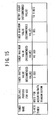
- FIG. 15 is a diagram showing the recommended values of the RFC-defined SCTP timer.
- a T3-rtx timer is specified as the timer for assuring the data transmission as in the embodiment.
- 3 sec. is specified as the recommended value of an initial value of this timer.
- the segmented data are sent via all the established associations, and, if the receiving-side communication device is unable to receive the data via any one of the associations, this is judged to be the association abnormality. Then, this unreceivable judgment involves using the receiving timer based on the present invention, and, if the receiving timer exceeds the abnormality detection threshold value, it is judged that the data can not be received.
- the communication device in the embodiment can detect the association abnormality at a high speed by setting the abnormality detection threshold value to a value smaller than the T3-rtx timer.
- the initial value of the abnormality detection threshold value is set equal to or smaller than a half of the timer value in a retry count "10" of the T3-rtx timer shown in FIG. 15.
- this abnormality detection threshold value may also be recalculated and changed based on an RTT (Round Trip Time) measurement.
- the transmitting-side communication device when the transmitting-side communication device transmits the data, the data are segmented by the number of the associations established between the transmission destination communication device, and the segmented data are transmitted via the respective associations, simultaneously.
- the receiving-side communication device if the associations established between the communication device as the transmission source include even one association with no data received, judges this to be the association abnormality.
- this abnormality detection threshold value is the time value used for judging whether or not the data can be received via the association and can be therefore set shorter than by the SCTP retransmission process.
- the receiving-side communication device can promptly detect the association abnormality.
- each communication device retains the common association information table and holds the communication state with respect to every association. Then, the communication device refers to this association information table and, if even one abnormal association exists, transmits the data via one normal association without segmenting the transmission data hereafter. In this case, "abnormal" is entered as the association state also in the association information table of the receiving-side communication device, and hence it is judged that the unsegmented data are transmitted thereto.
- the data can be normally transmitted.
- the transmission number is assigned to every segmented data, and the segmented data are transmitted together with the transmission number.
- the received data are reassembled in sequence according to the transmission number thereof and can be thereby restored into the original data.
- the [abnormal association detected state] is assessed as the period till the abnormality-occurred association is specified since the association abnormality was detected, and that communication device, if there is the data transmission request during this period, segments and thus transmits the data without referring to the association information table.
- the communication device serving originally as the transmitting-side device is also unable to receive the data via the abnormality-occurred association and can therefore make the same judgment about the association abnormality as the receiving-side communication device judges.
- the communication device actualizes the aforementioned functions by newly providing the signal transmission control unit and the signal reception control unit by adding none of special functions to the SCTP stack.
- This configuration enables the aforementioned functions to be actualized without any loss of the existing SCTP advantages.
Landscapes
- Engineering & Computer Science (AREA)
- Computer Networks & Wireless Communication (AREA)
- Signal Processing (AREA)
- Computer Security & Cryptography (AREA)
- Quality & Reliability (AREA)
- Communication Control (AREA)
- Data Exchanges In Wide-Area Networks (AREA)
- Maintenance And Management Of Digital Transmission (AREA)
Applications Claiming Priority (1)
| Application Number | Priority Date | Filing Date | Title |
|---|---|---|---|
| JP2005094929A JP4153502B2 (ja) | 2005-03-29 | 2005-03-29 | 通信装置及び論理リンク異常検出方法 |
Publications (1)
| Publication Number | Publication Date |
|---|---|
| EP1708445A1 true EP1708445A1 (de) | 2006-10-04 |
Family
ID=36337409
Family Applications (1)
| Application Number | Title | Priority Date | Filing Date |
|---|---|---|---|
| EP20050014022 Withdrawn EP1708445A1 (de) | 2005-03-29 | 2005-06-29 | Kommunikationsvorrichtung und Feststellungsmethode für logische Verbindung Anomalie |
Country Status (3)
| Country | Link |
|---|---|
| US (1) | US7965625B2 (de) |
| EP (1) | EP1708445A1 (de) |
| JP (1) | JP4153502B2 (de) |
Cited By (4)
| Publication number | Priority date | Publication date | Assignee | Title |
|---|---|---|---|---|
| WO2008138919A1 (en) * | 2007-05-14 | 2008-11-20 | Abb Technology Ag | Redundant computers and computer communication networks in a high-voltage power transmission system |
| US8305782B2 (en) | 2007-05-14 | 2012-11-06 | Abb Technology Ag | Redundant current valve control in a high voltage power transmission system |
| US8532144B2 (en) | 2007-05-14 | 2013-09-10 | Abb Technology Ag | Point-to-point communication in a high voltage power transmission system |
| CN101523356B (zh) * | 2007-05-14 | 2013-09-11 | Abb技术有限公司 | 高压输电系统中的冗余计算机和计算机通信网络 |
Families Citing this family (9)
| Publication number | Priority date | Publication date | Assignee | Title |
|---|---|---|---|---|
| US8144688B2 (en) * | 2005-12-07 | 2012-03-27 | Tektronix, Inc. | System and method for discovering SCTP associations in a network |
| US7706281B2 (en) * | 2006-01-06 | 2010-04-27 | Cisco Technology, Inc. | Selecting paths in multi-homed transport-layer network associations |
| JP4998316B2 (ja) * | 2008-02-20 | 2012-08-15 | 富士通株式会社 | 通信システム及び通信処理方法並びにノード |
| JP5075784B2 (ja) * | 2008-10-01 | 2012-11-21 | 株式会社エヌ・ティ・ティ・ドコモ | 移動通信システム及び送信側ノード |
| JP5310227B2 (ja) | 2009-04-22 | 2013-10-09 | 富士通株式会社 | 通信装置 |
| CN101873259B (zh) * | 2010-06-01 | 2013-01-09 | 华为技术有限公司 | Sctp报文识别方法和装置 |
| JP5918076B2 (ja) * | 2012-08-22 | 2016-05-18 | Kddi株式会社 | マルチホーム通信方法およびシステム |
| WO2015118553A1 (en) * | 2014-02-06 | 2015-08-13 | Council Of Scientific & Industrial Research | Method and device for detecting a malicious sctp receiver terminal |
| US10891179B2 (en) * | 2018-10-22 | 2021-01-12 | Western Digital Technologies, Inc. | Data storage device with deadlock recovery capabilities |
Citations (4)
| Publication number | Priority date | Publication date | Assignee | Title |
|---|---|---|---|---|
| WO2003094477A1 (en) * | 2002-04-29 | 2003-11-13 | Nokia Corporation | Internet protocol based system |
| US20030235151A1 (en) * | 2002-06-24 | 2003-12-25 | Compaq Information Technologies Group, L.P. | Active path selection for SCTP |
| US6778495B1 (en) * | 2000-05-17 | 2004-08-17 | Cisco Technology, Inc. | Combining multilink and IP per-destination load balancing over a multilink bundle |
| US20050047391A1 (en) * | 2003-08-26 | 2005-03-03 | Michael Tuxen | Selection method for message paths in communication systems |
Family Cites Families (11)
| Publication number | Priority date | Publication date | Assignee | Title |
|---|---|---|---|---|
| US4627045A (en) * | 1984-02-14 | 1986-12-02 | Rosemount Inc. | Alternating communication channel switchover system |
| JPH05260060A (ja) | 1992-03-09 | 1993-10-08 | Matsushita Electric Ind Co Ltd | 通信装置 |
| JP3137744B2 (ja) | 1992-06-25 | 2001-02-26 | 三菱電機株式会社 | 複数経路型データ転送方式 |
| JPH0653982A (ja) | 1992-07-29 | 1994-02-25 | Nec Corp | Atm通話路の系切り替え方式 |
| JP3449541B2 (ja) * | 1999-12-22 | 2003-09-22 | 日本電気株式会社 | データパケット転送網とデータパケット転送方法 |
| US7027389B2 (en) * | 2000-12-11 | 2006-04-11 | Cisco Technology, Inc. | Fast failure detection using RTT time considerations on a non-retransmit medium |
| US6694471B1 (en) * | 2000-12-27 | 2004-02-17 | Cisco Technology, Inc. | System and method for periodic retransmission of messages |
| WO2003013065A1 (en) * | 2001-08-02 | 2003-02-13 | Sun Microsystems, Inc. | Method and system for node failure detection |
| US20080002669A1 (en) * | 2001-09-14 | 2008-01-03 | O'brien Ray | Packet voice gateway |
| WO2005046125A1 (en) * | 2003-10-28 | 2005-05-19 | Docomo Communications Laboratories Usa, Inc. | Method for supporting scalable and reliable multicast in tdma/tdd systems using feedback suppression techniques |
| EP1813063A4 (de) * | 2004-11-19 | 2009-08-12 | Stevens Inst Technology | Endgerät mit mehrfachzugang und der möglichkeit simultaner konnektivität zu mehreren kommunikationskanälen |
-
2005
- 2005-03-29 JP JP2005094929A patent/JP4153502B2/ja not_active Expired - Fee Related
- 2005-06-29 EP EP20050014022 patent/EP1708445A1/de not_active Withdrawn
- 2005-06-30 US US11/171,629 patent/US7965625B2/en not_active Expired - Fee Related
Patent Citations (4)
| Publication number | Priority date | Publication date | Assignee | Title |
|---|---|---|---|---|
| US6778495B1 (en) * | 2000-05-17 | 2004-08-17 | Cisco Technology, Inc. | Combining multilink and IP per-destination load balancing over a multilink bundle |
| WO2003094477A1 (en) * | 2002-04-29 | 2003-11-13 | Nokia Corporation | Internet protocol based system |
| US20030235151A1 (en) * | 2002-06-24 | 2003-12-25 | Compaq Information Technologies Group, L.P. | Active path selection for SCTP |
| US20050047391A1 (en) * | 2003-08-26 | 2005-03-03 | Michael Tuxen | Selection method for message paths in communication systems |
Cited By (5)
| Publication number | Priority date | Publication date | Assignee | Title |
|---|---|---|---|---|
| WO2008138919A1 (en) * | 2007-05-14 | 2008-11-20 | Abb Technology Ag | Redundant computers and computer communication networks in a high-voltage power transmission system |
| US8305782B2 (en) | 2007-05-14 | 2012-11-06 | Abb Technology Ag | Redundant current valve control in a high voltage power transmission system |
| US8493866B2 (en) | 2007-05-14 | 2013-07-23 | Abb Technology Ag | Redundant computers and computer communication networks in a high-voltage power transmission system |
| US8532144B2 (en) | 2007-05-14 | 2013-09-10 | Abb Technology Ag | Point-to-point communication in a high voltage power transmission system |
| CN101523356B (zh) * | 2007-05-14 | 2013-09-11 | Abb技术有限公司 | 高压输电系统中的冗余计算机和计算机通信网络 |
Also Published As
| Publication number | Publication date |
|---|---|
| US20060221840A1 (en) | 2006-10-05 |
| US7965625B2 (en) | 2011-06-21 |
| JP4153502B2 (ja) | 2008-09-24 |
| JP2006279467A (ja) | 2006-10-12 |
Similar Documents
| Publication | Publication Date | Title |
|---|---|---|
| US6954797B1 (en) | Data Communication method, terminal equipment, interconnecting installation, data communication system and recording medium | |
| US6694471B1 (en) | System and method for periodic retransmission of messages | |
| US6741555B1 (en) | Enhancement of explicit congestion notification (ECN) for wireless network applications | |
| US6760766B1 (en) | Data transmission method and device | |
| US7471681B2 (en) | Determining network path transmission unit | |
| EP0796533B1 (de) | Mehrrechnerumgebungen | |
| US7929422B2 (en) | Method of moving a transport connection among network hosts | |
| US20020054570A1 (en) | Data communication system, data communication method, and recording medium with data communication program recorded thereon | |
| US20070171828A1 (en) | Method of determining a maximum transmission unit value of a network path using transport layer feedback | |
| US9031076B2 (en) | Processing requests | |
| CN106576108B (zh) | 通信系统中的通信方法和设备及系统 | |
| EP1295428A2 (de) | Verbesserung von tcp-protokoll für drahtlose netzwerkanwendungen | |
| CN1582583A (zh) | 用于无线接口上tcp性能改善的双重代理方法 | |
| US7965625B2 (en) | Communication device and logical link abnormality detection method | |
| US7480301B2 (en) | Method, system and article for improved TCP performance during retransmission in response to selective acknowledgement | |
| Floyd et al. | RFC2883: An extension to the selective acknowledgement (SACK) option for TCP | |
| JP4229807B2 (ja) | データ転送方法とtcpプロキシ装置およびそれを用いたネットワークシステム | |
| US7978598B1 (en) | Connection replication | |
| EP1851893B1 (de) | Verfahren und system zur wiederherstellung von zustandsinformationen eines ersten tunnelendpunkts in einem l2tp-netzwerk (layer two tunnelling protocol) | |
| US9118521B2 (en) | Method and apparatus for controlling an SCTP protocol instance | |
| CN101184032A (zh) | 一种堆叠系统设备通讯的方法 | |
| US7535916B2 (en) | Method for sharing a transport connection across a multi-processor platform with limited inter-processor communications | |
| US7623546B1 (en) | Latency improvement for file transfers over network connections | |
| JP2001136209A (ja) | 通信装置 | |
| JP2001308936A (ja) | データ通信方法、中継装置、データ通信システム及びその記録媒体 |
Legal Events
| Date | Code | Title | Description |
|---|---|---|---|
| PUAI | Public reference made under article 153(3) epc to a published international application that has entered the european phase |
Free format text: ORIGINAL CODE: 0009012 |
|
| AK | Designated contracting states |
Kind code of ref document: A1 Designated state(s): AT BE BG CH CY CZ DE DK EE ES FI FR GB GR HU IE IS IT LI LT LU MC NL PL PT RO SE SI SK TR |
|
| AX | Request for extension of the european patent |
Extension state: AL BA HR LV MK YU |
|
| AKX | Designation fees paid | ||
| STAA | Information on the status of an ep patent application or granted ep patent |
Free format text: STATUS: THE APPLICATION IS DEEMED TO BE WITHDRAWN |
|
| 18D | Application deemed to be withdrawn |
Effective date: 20070701 |
|
| REG | Reference to a national code |
Ref country code: DE Ref legal event code: 8566 |