EP1708140A2 - Unresolved target detection improvement by use of multiple matched filters approach at different spatial phases - Google Patents
Unresolved target detection improvement by use of multiple matched filters approach at different spatial phases Download PDFInfo
- Publication number
- EP1708140A2 EP1708140A2 EP06112003A EP06112003A EP1708140A2 EP 1708140 A2 EP1708140 A2 EP 1708140A2 EP 06112003 A EP06112003 A EP 06112003A EP 06112003 A EP06112003 A EP 06112003A EP 1708140 A2 EP1708140 A2 EP 1708140A2
- Authority
- EP
- European Patent Office
- Prior art keywords
- image data
- filtered
- spatial
- phases
- filters
- Prior art date
- Legal status (The legal status is an assumption and is not a legal conclusion. Google has not performed a legal analysis and makes no representation as to the accuracy of the status listed.)
- Granted
Links
Images




Classifications
-
- G—PHYSICS
- G06—COMPUTING OR CALCULATING; COUNTING
- G06T—IMAGE DATA PROCESSING OR GENERATION, IN GENERAL
- G06T7/00—Image analysis
- G06T7/70—Determining position or orientation of objects or cameras
-
- G—PHYSICS
- G06—COMPUTING OR CALCULATING; COUNTING
- G06F—ELECTRIC DIGITAL DATA PROCESSING
- G06F18/00—Pattern recognition
- G06F18/20—Analysing
- G06F18/25—Fusion techniques
- G06F18/253—Fusion techniques of extracted features
-
- G—PHYSICS
- G06—COMPUTING OR CALCULATING; COUNTING
- G06V—IMAGE OR VIDEO RECOGNITION OR UNDERSTANDING
- G06V10/00—Arrangements for image or video recognition or understanding
- G06V10/20—Image preprocessing
- G06V10/255—Detecting or recognising potential candidate objects based on visual cues, e.g. shapes
-
- G—PHYSICS
- G06—COMPUTING OR CALCULATING; COUNTING
- G06V—IMAGE OR VIDEO RECOGNITION OR UNDERSTANDING
- G06V10/00—Arrangements for image or video recognition or understanding
- G06V10/40—Extraction of image or video features
- G06V10/44—Local feature extraction by analysis of parts of the pattern, e.g. by detecting edges, contours, loops, corners, strokes or intersections; Connectivity analysis, e.g. of connected components
- G06V10/443—Local feature extraction by analysis of parts of the pattern, e.g. by detecting edges, contours, loops, corners, strokes or intersections; Connectivity analysis, e.g. of connected components by matching or filtering
-
- G—PHYSICS
- G06—COMPUTING OR CALCULATING; COUNTING
- G06V—IMAGE OR VIDEO RECOGNITION OR UNDERSTANDING
- G06V10/00—Arrangements for image or video recognition or understanding
- G06V10/70—Arrangements for image or video recognition or understanding using pattern recognition or machine learning
- G06V10/77—Processing image or video features in feature spaces; using data integration or data reduction, e.g. principal component analysis [PCA] or independent component analysis [ICA] or self-organising maps [SOM]; Blind source separation
- G06V10/80—Fusion, i.e. combining data from various sources at the sensor level, preprocessing level, feature extraction level or classification level
- G06V10/806—Fusion, i.e. combining data from various sources at the sensor level, preprocessing level, feature extraction level or classification level of extracted features
-
- G—PHYSICS
- G06—COMPUTING OR CALCULATING; COUNTING
- G06T—IMAGE DATA PROCESSING OR GENERATION, IN GENERAL
- G06T2207/00—Indexing scheme for image analysis or image enhancement
- G06T2207/10—Image acquisition modality
- G06T2207/10048—Infrared image
Definitions
- the present invention relates generally to unresolved target detection using an infrared focal plane array and matched filters, and it more particularly relates to an unresolved target detection technique using multiple matched filters.
- IR FPA has been broadly used for sensors in all three major platforms: airborne sensing, satellite sensing, as well as ground sensing.
- passive IR (Infrared) sensors are widely used to detect the energy emitted from targets, backgrounds, incoming threats, and the atmosphere for a plurality of applications including military surveillance, missile target and detection systems, crop and forest management, weather forecasting, and other applications.
- the Matched Filter (MF) method is currently a popular approach for unresolved target detection using IR FPAs as sensor detect.
- DPSF discrete point spread function sampled by discrete pixels in IR FPA
- CPSF continuous point spread function
- a matched spatial filter is obtained by dividing the DPSF with the co-variance matrix of background clutter. This matched filter is optimal in an MSE (mean-square-error) sense In that it provides a maximum SCNR (signal to clutter noise ratio) for a point source (unresolved) target.
- a DPSF In current advanced optical designs, most energy of a DPSF can be contained within a 3x3 pixel area, and the PVF (point visibility function) can be as high as 0.6-0.75.
- a 0.7 PVF means that ff the peak of a CPSF is located at the center of a pixel, this pixel will contain 70% of the energy of the CPSF and 30% of its energy is spread out in the neighbor pixels.
- CPSF is a symmetrical Mexican-hat shape function
- spatial phase means the local on of the CPSF peak at the sub-pixel space. If the peak is aligned with the center of a pixel, we call it a center phase.
- a corner phase means that the peak falls down on a corner of a pixel. In this case, all the four pixels nearby that corner will receive equal energy from the CPSF. Therefore, it is clear that a 3x3 DPSF of a center phase has a totally different shape of energy distribution from a 3x3 DPSF of a corner phase, as evidenced in Figs. 2(a) and (b).
- the PVF of the CPSF is 0.73.
- any sub-pixel location should have an equal probability to be aligned with the CPSF peak. That is, the spatial phase is a random variable with a uniform distribution.
- the random phase causes problems in target detection using the MF method.
- the DPSF of center phase (or averaged phase) is used to obtain the matched filter. Therefore, if the target center is located near the center of a pixel, the MF method performs well. However, if the target center is located near pixel corners or edges, the performance will be worse because the matched filter is not matched to the DPSF of the corner (or edge) phase.
- a sensor which is preferably an Infrared focal plane array, includes a plurality of pixels for providing image data.
- a processor processes the image data from a selected pixel corresponding to a potential point source target and from a plurality of neighboring pixels.
- the multiple filters have a plurality of different phases, including at least a center phase and four corner phases.
- the multiple filters filter the image data to obtain different filtered spatial images.
- the filtered spatial images are preferably normalized and averaged.
- the intensities of the filtered spatial images are also preferably summed.
- a detector which is preferably a CFAR detector, detects a target based upon the spatially filtered images from the multiple matched filters. Preferably, either five or nine matched filters are utilized.
- an MMF (multiple matched filters) method is described that can significantly improve detection performance for unresolved targets. Performance evaluations were conducted using images from an airborne sensor and a satellite sensor.
- Fig. 1 illustrates an exemplary SMF (single matched filter) image processing system 100 found in the prior art.
- Figs. 2A and 2B are matrices which respectively represent a 3x3 DPSF of a pixel center phase, and a 3x3 DPSF of a pixel corner phase.
- Fig. 3 is a photograph of a cloud scene that appears as a background clutter image.
- Fig. 4 is a diagram illustrating the performance of a traditional single MF method having six phases among a possible 121 phases.
- Figs. 5A and 5B are graphs that compare the performances of seven different matched filters.
- Fig. 6A and 6B are diagrams illustrating both a five MMF approach and a nine MMF approach.
- Fig. 7 is a block diagram of the five MMF detection process.
- Fig. 8 is an illustration of the averaging process for the phase associated with an upper left corner.
- Fig. 9 is an Illustration of the averaging process for the nine MMF Method.
- Figs. 10A and 10B are graphs that show detection performance comparisons between the five-MMF method (dashed curve with triangles) and the traditional single MF method using the averaged phase filter (solid curve with circles).
- Figs. 11A and 11B are graphs that show detection performance comparisons between the nine-MMF method (dashed curve with triangles) and the traditional single MF method using the averaged phase filter (solid curve with circles).
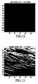
- Fig, 12 shows a relatively low clutter scene in a satellite image.
- Fig. 13 shows a relatively medium/heavy clutter scene in a satellite image.
- Fig. 14 shows the residual image after LS time-d'fferencing from the medium/heavy clouds clutter shown in Fig. 13.
- Fig. 15 is a graph showing ROC curve comparisons for a low clutter scene.
- Fig. 16 is a graph showing ROC curve comparison: before and after LS time-differencing.
- Fig. 17 is a graph showing ROC curve comparisons for the residual image after time-differencing.
- MMF Multiple Matched Filters
- This approach applies a neighbor-fusion strategy for spatial noise reduction to increase SCNR.
- the phasing problem is a universal problem to different sensors using IR FPA.
- the outputs from MMF can also be used for improving sub-pixel centrolding performance.
- the present invention has been tested with a cloud scene as the background clutter image, as shown in Fig. 3.
- Fig. 4' illustrates the performance of a traditional single MF method having six phases among a possible 121 phases.
- Phase P1 is the left-upper corner phase
- phase P6 is the center phase.
- the traditional MF method uses a single MF. Its performance Is shown In Fig. 5 at two different SCNRs, The performances of seven different matched filters were compared.
- MFs # 1 to 6 are obtained by using different DPSFs with the six different phases shown In Fig. 4.
- MF # 7 Is obtained by using the averaged DPSF of the 121 phases, It is seen that the averaged-phase MF performs the best among the seven MFs.
- the present invention is directed to a multiple MF (MMF) method where the input image is filtered by MMFs, and the multiple filtered images are processed using a neighbor-fusion scheme to suppress random noise and to increase SCNR.
- MMF multiple MF
- the present invention includes both a five MMF approach and a nine MMF approach. As shown in Fig. 6, the phases of the five MMFs are the corner phases P1-P4 and the center phase P5, and the nine MMFs have four additional edge phases.
- FIG. 7 The block diagram of the five MMF detection process is illustrated in Fig. 7.
- a reference image (t) is processed in step 60 to estimate a variance of sigma and to chose a spatial filter 61-65.
- the "averaging process” step 66 in Fig. 7 is the core function that averages the four corner phasing filter outputs at different pixel locations. This function can reduce spatial random noise standard deviation (sigma) by half without reducing the target intensity at the corners.
- the next “additive process” step 67 then sums the detected intensities from all the filters 61-65 at the five phase locations (or nine phase locations in the nine MMF technique) before flowing to the "CFAR detection” step 68.
- averaged fusion performs better than other fusion strategies such as MAX or MIN fusions.
- the variance of a RV can be reduced to one fourth of its original variance by averages four of its events at different spaces or times.
- the inputs to the averaging process 66 are five SNR Images
- the original image is first filtered by use of the five MF's 61-65 of different phases to obtained five different spatial images.
- the five spatial images are then normalized (divided) by a background estimator to obtain five SNR images.
- the background normalization process is a nonlinear process.
- the point source target will have its energy equally distributed in the pixel 84 and its three neighbor pixels: the left pixel 83, the left-upper pixel 81, and the upper pixel 82.
- the energy can be optimally detected using the MF of phase P2 (right-upper phase).
- the energy can be optimally detected using the MF of phase P4 (right-lower phase) and phase P3 (left-lower phase), respectively.
- NbFn_ 1 ( i i , j j ) [ snr_ 1 ( i i , j j ) + snr_ 2 ( i i , j j ⁇ 1 ) + snr_ 3 ( i i ⁇ 1 , j j ) + snr_ 4 ( i i ⁇ 1 , j j ⁇ 1 ) ] / 4 , where snr_1(ii,jj) is the SNR image filtered using MF of phase 1, snr_ 2( ii,jj-1 ) is the SNR Image filtered using MF of phase P2 with one pixel shift to the left, snr_3 ( ii-1,jj ) is the SNR image filtered using MF of phase P3 with one pixel shift to the upper direction, and snr_4 (ii-1, jj )
- NbFn_ 2 ( i i , j j ) [ snr_ 2 ( i i , j j ) + snr_ 1 ( i i , j j + 1 ) + snr_ 4 ( i i ⁇ 1 , j j ) + snr_ 3 ( i i ⁇ 1 , j j + 1 ) ] / 4
- NbFn_ 3 ( i i , j j ) [ snr_ 3 ( i i , j j ) + snr_ 4 ( i i , j j ⁇ 1 ) + snr_ 1 ( i i + 1 , j j ) + snr_ 2 ( i i + 1 , j j ⁇ 1 ) ] / 4
- NbFn_ 3 ( i i , j j ) [ s
- NbFn_ 4 ( i i , j j ) [ snr_ 4 ( i i , j j ) + snr_ 5 ( i i , j j ⁇ 1 ) ] / 2
- NbFn_ 5 ( i i , j j ) [ snr_ 5 ( i i , j j ) + snr_ 5 ( i i , j j + 1 ) ] / 2
- NbFn_ 2 ( i i , j j ) [ snr_ 2 ( i i , j j ) + [ snr_ 2 ( i i , j j ) + [ snr_ 2 ( i i , j j ) +
- an alternative averaging process is to first average the four MFs with corner phases with appropriate pixel shifts.
- the resulting averaged MF is of a larger size.
- the original MF's have a size of 3x3.
- the averaged MF will have a size of 5x5.
- the four 5x5 averaged MFs are then used to filter the original image to obtain four different spatial images. They are then normalized by a background estimator to obtain four SNR images.
- the edge MFs can be averaged to a larger 3x5 or 5x3 MF depending on its edge locations.
- the output of the MF with a center phase is large when the point source target phase is near the pixel center.
- the obtained neighbor-fused SNR image goes to the traditional CFAR process to report detections for a specific false detection rate Pfa, or go to a multiple thresholding process to generate ROC curves to evaluate the performance of the algorithms.
- the Pfa is reduced by about 20-30 times. That is, with 4 additional MFs of edge phases, the Pfa is further reduced by about 3 times, compared with the results using the five-MMF method
- a low clutter and a madium/heavy clutter scene of satellite images are shown in Figs. 12 and 13, respectively.
- the STD (standard deviation) of the medium/heavy clutter is almost 15 times as large as the STD of the low clutter (the medium/heavy clutter in the satellite image is similar to heavy clutter in airborne sensor images).
- the MMF method of the present invention is most efficient for improving detection for low and medium background clutter where random noise contributes as well as the correlated clutter noise, For example, the clouds scene in Fig. 3 is considered as a medium clutter for airborne IR sensors.
- the medium/heavy clutter shown in Fig. 13 is dominated by spatially correlated clutter noise.
- LS least-square time-differencing process of the type described in M. Fernandez, A. Aridgides, D. Randolph, and D. Ferris, "Optimal Subpixel-Level IR Frame-to-Frame Registration," SPIE Proceedings of Signal and Data Processing of Small Targets, vol. 1481, pp. 172-179, 1991 .
- This technique reduces most of the correlated clutter and the MMF method is applied to further improve detection performance.
- Fig. 14 shows the residual image after the LS time-differencing (using a 5x5 correlated filter) from the medium/heavy clouds clutter shown in Fig. 13.
- the clutter STD is significantly reduced from 31 counts to 1.84 counts.
- Fig. 16 shows detection performance comparison before and after LS time-differencing, and also shows the performance of direct time-differencing without using LS process.
- the background clutter used is the one shown in Fig. 13.
- the curve with 'triangle' symbols In Fig. 16 shows the detection performance on the original clutter image (before time-differencing),
- the other three curves in Fig. 16 also used the same target intensity.
- the curve with 'star' symbols in Fig. 16 shows the detection performance of direct time-differencing (direct subtraction between the current frame and the previous frame without using LS correlation process). It is seen that direct time-differencing performs better than no time-differencing.
- the curves with 'circle' symbols and 'cross' symbols in Fig. 16 show the detection performance of LS time-differencing using a 5x5 and a 3x3 correlation filters, respectively.
- the 5x5 filter performs a little better. It is seen that LS time-differencing performs much better than no time-differencing.
- the Pfa is reduced by more than 100 times. All the four curves in Fig. 15 are performance using the traditional single MF method with the averaged phase filter. In Fig. 16, we will show that by applying the nine-MMF method we can further reduce the Pfa by another factor of 30 times, so that the total false alarms reduction is about 3,000 times.
- the processing time for MMF method is still fast enough.
- the processing time required for spatial processing the five multiple MFs is less than that required for a single MF process with a larger filter size of 7x7.
- the nine MMF method performs better than the five MMF method. Therefore, the MMF method can be further improved by adding more MFs with edge phases.
- the outputs from MMF can be further used for improving sub-pixel centrolding performance.
- the centrolding errors can be reduced by a factor of 40%. and for a high SCNR, the centroiding errors can be further reduced by more than 50%.
- the performance for heavy clutter is worse than that for low clutter, even though time-differencing techniques are applied This is because the time-differencing process will cause a 40% increase of random noise Sigma.
- the present has shown that by combining time-differencing techniques with the MMF method, the Pfa caused by both the correlated clutter and random noise can be significantly reduced, and thus the performance for heavy clutter will be close to that for low clutter.
Landscapes
- Engineering & Computer Science (AREA)
- Theoretical Computer Science (AREA)
- Computer Vision & Pattern Recognition (AREA)
- General Physics & Mathematics (AREA)
- Physics & Mathematics (AREA)
- Multimedia (AREA)
- Evolutionary Computation (AREA)
- Artificial Intelligence (AREA)
- Data Mining & Analysis (AREA)
- Life Sciences & Earth Sciences (AREA)
- Bioinformatics & Cheminformatics (AREA)
- Computing Systems (AREA)
- Software Systems (AREA)
- Health & Medical Sciences (AREA)
- Medical Informatics (AREA)
- General Health & Medical Sciences (AREA)
- Databases & Information Systems (AREA)
- Bioinformatics & Computational Biology (AREA)
- Evolutionary Biology (AREA)
- General Engineering & Computer Science (AREA)
- Image Processing (AREA)
- Image Analysis (AREA)
- Radar Systems Or Details Thereof (AREA)
- Geophysics And Detection Of Objects (AREA)
Abstract
Description
- The present invention relates generally to unresolved target detection using an infrared focal plane array and matched filters, and it more particularly relates to an unresolved target detection technique using multiple matched filters.
- With the advancement of IR FPA manufacturing technology, IR FPA has been broadly used for sensors in all three major platforms: airborne sensing, satellite sensing, as well as ground sensing. For example, passive IR (Infrared) sensors are widely used to detect the energy emitted from targets, backgrounds, incoming threats, and the atmosphere for a plurality of applications including military surveillance, missile target and detection systems, crop and forest management, weather forecasting, and other applications.
- U,S. Patent Application S.N.
10/395,269 - The Matched Filter (MF) method is currently a popular approach for unresolved target detection using IR FPAs as sensor detect. In the MF method, DPSF (discrete point spread function sampled by discrete pixels in IR FPA) is estimated from CPSF (continuous point spread function). CPSF is available based on the sensor optical and lens designs. A matched spatial filter is obtained by dividing the DPSF with the co-variance matrix of background clutter. This matched filter is optimal in an MSE (mean-square-error) sense In that it provides a maximum SCNR (signal to clutter noise ratio) for a point source (unresolved) target.
- In current advanced optical designs, most energy of a DPSF can be contained within a 3x3 pixel area, and the PVF (point visibility function) can be as high as 0.6-0.75. A 0.7 PVF means that ff the peak of a CPSF is located at the center of a pixel, this pixel will contain 70% of the energy of the CPSF and 30% of its energy is spread out in the neighbor pixels. Although CPSF is a symmetrical Mexican-hat shape function, the shape of a DPSF varies depending on the spatial phases, spatial phase means the local on of the CPSF peak at the sub-pixel space. If the peak is aligned with the center of a pixel, we call it a center phase. Similarly, a corner phase means that the peak falls down on a corner of a pixel. In this case, all the four pixels nearby that corner will receive equal energy from the CPSF. Therefore, it is clear that a 3x3 DPSF of a center phase has a totally different shape of energy distribution from a 3x3 DPSF of a corner phase, as evidenced in Figs. 2(a) and (b). The PVF of the CPSF is 0.73.
- Theoretically there are infinite different phases. In practice, we can approximate the infinite phases by dividing a pixel into multiple sub-pixels, For example, if we divide a pixel into 11x11 sub-pixels, then we have 121 different phases to approximate all the infinite phases. At any time moment, any sub-pixel location should have an equal probability to be aligned with the CPSF peak. That is, the spatial phase is a random variable with a uniform distribution.
- From the discussion above, it is clear that the random phase causes problems in target detection using the MF method. In the traditional MF method approach, the DPSF of center phase (or averaged phase) is used to obtain the matched filter. Therefore, if the target center is located near the center of a pixel, the MF method performs well. However, if the target center is located near pixel corners or edges, the performance will be worse because the matched filter is not matched to the DPSF of the corner (or edge) phase.
- Accordingly, there is a need to improve target detection of a point source target, when utilizing a matched filter and when the target center is located away from the pixel center.
- The method and system of the present invention, which includes multiple matched filters, substantially overcome the previously described problem of a point source target center not being aligned with a pixel center when utilizing a matched filter. A sensor. which is preferably an Infrared focal plane array, includes a plurality of pixels for providing image data. A processor processes the image data from a selected pixel corresponding to a potential point source target and from a plurality of neighboring pixels. The multiple filters have a plurality of different phases, including at least a center phase and four corner phases. The multiple filters filter the image data to obtain different filtered spatial images. The filtered spatial images are preferably normalized and averaged. The intensities of the filtered spatial images are also preferably summed. A detector, which is preferably a CFAR detector, detects a target based upon the spatially filtered images from the multiple matched filters. Preferably, either five or nine matched filters are utilized.
- In the present invention, an MMF (multiple matched filters) method is described that can significantly improve detection performance for unresolved targets. Performance evaluations were conducted using images from an airborne sensor and a satellite sensor.
- Fig. 1 illustrates an exemplary SMF (single matched filter)
image processing system 100 found in the prior art. - Figs. 2A and 2B are matrices which respectively represent a 3x3 DPSF of a pixel center phase, and a 3x3 DPSF of a pixel corner phase.
- Fig. 3 is a photograph of a cloud scene that appears as a background clutter image.
- Fig. 4 is a diagram illustrating the performance of a traditional single MF method having six phases among a possible 121 phases.
- Figs. 5A and 5B are graphs that compare the performances of seven different matched filters.
- Fig. 6A and 6B are diagrams illustrating both a five MMF approach and a nine MMF approach.
- Fig. 7 is a block diagram of the five MMF detection process.
- Fig. 8 is an illustration of the averaging process for the phase associated with an upper left corner.
- Fig. 9 is an Illustration of the averaging process for the nine MMF Method.
- Figs. 10A and 10B are graphs that show detection performance comparisons between the five-MMF method (dashed curve with triangles) and the traditional single MF method using the averaged phase filter (solid curve with circles).
- Figs. 11A and 11B are graphs that show detection performance comparisons between the nine-MMF method (dashed curve with triangles) and the traditional single MF method using the averaged phase filter (solid curve with circles).
- Fig, 12 shows a relatively low clutter scene in a satellite image.
- Fig. 13 shows a relatively medium/heavy clutter scene in a satellite image.
- Fig. 14 shows the residual image after LS time-d'fferencing from the medium/heavy clouds clutter shown in Fig. 13.
- Fig. 15 is a graph showing ROC curve comparisons for a low clutter scene.
- Fig. 16 is a graph showing ROC curve comparison: before and after LS time-differencing.
- Fig. 17 is a graph showing ROC curve comparisons for the residual image after time-differencing.
- In order to facilitate the reader's understanding of the present invention, the following list of acronyms and their general meanings are provided,
- CFAR -
- Constant False Alarm Rate
- CPSF -
- Continuous Point Spread Function
- DPSF -
- Discrete Point Spread Function
- FOR -
- Field of Regard
- FOV -
- Field of View
- FPA -
- Focal Plane Array
- IR -
- Infrared
- IRST -
- Infrared Search and Track
- LOS -
- Line of Sight
- LS -
- Least-Square
- MF -
- Matched filter
- MMF -
- Multiple Matched Filters
- MFA -
- Multiple-Frame-Association
- MSE -
- Mean-Square-Error
- MTI -
- Moving Target Indicator
- NEDT -
- Noise-Equivalent Temperature Difference
- Pd -
- Probability of Detection
- Pfa -
- Probability of False-Alarm
- PSF -
- Point spread function
- PVF -
- Point Visibility Function
- ROC -
- Receiver Operating Characteristics
- S/N
- - Signal-to-Noise Ratio
- SCNR -
- Signal to Clutter Noise Ratio
- STD -
- Spot Time-Differencing
- The present mention is directed to a MMF (Multiple Matched Filters) method having multiple matched filters at different spatial phases to improve detection performance. This approach applies a neighbor-fusion strategy for spatial noise reduction to increase SCNR. The phasing problem is a universal problem to different sensors using IR FPA. In addition to improving detection performance, the outputs from MMF can also be used for improving sub-pixel centrolding performance.
- The present invention has been tested with a cloud scene as the background clutter image, as shown in Fig. 3. In the preliminary testing, a point-source target was randomly inserted to the cloud background in 121 different phases. For each phase, it was randomly inserted twelve times. According the total target insertion number was 121x12 =1452.
- Fig. 4' illustrates the performance of a traditional single MF method having six phases among a possible 121 phases. Phase P1 is the left-upper corner phase, and phase P6 is the center phase. The traditional MF method uses a single MF. Its performance Is shown In Fig. 5 at two different SCNRs, The performances of seven different matched filters were compared.
MFs # 1 to 6 are obtained by using different DPSFs with the six different phases shown In Fig. 4.MF # 7 Is obtained by using the averaged DPSF of the 121 phases, It is seen that the averaged-phase MF performs the best among the seven MFs. - Instead of using a single MF, the present invention is directed to a multiple MF (MMF) method where the input image is filtered by MMFs, and the multiple filtered images are processed using a neighbor-fusion scheme to suppress random noise and to increase SCNR. The present invention includes both a five MMF approach and a nine MMF approach. As shown in Fig. 6, the phases of the five MMFs are the corner phases P1-P4 and the center phase P5, and the nine MMFs have four additional edge phases.
- The block diagram of the five MMF detection process is illustrated in Fig. 7. A reference image (t) is processed in
step 60 to estimate a variance of sigma and to chose a spatial filter 61-65. The "averaging process"step 66 in Fig. 7 is the core function that averages the four corner phasing filter outputs at different pixel locations. This function can reduce spatial random noise standard deviation (sigma) by half without reducing the target intensity at the corners. The next "additive process"step 67 then sums the detected intensities from all the filters 61-65 at the five phase locations (or nine phase locations in the nine MMF technique) before flowing to the "CFAR detection"step 68. - As disclosed copending patent application S.N. 10/395,269 by Chen et al. entitled "Integrated Spatio-Temporal Multiple Sensor Fusion System Design", averaged fusion (equivalent to additive fusion) performs better than other fusion strategies such as MAX or MIN fusions. For example, the variance of a RV (random variable) can be reduced to one fourth of its original variance by averages four of its events at different spaces or times.
- As shown in Fig. 7, the inputs to the
averaging process 66 are five SNR Images The original image is first filtered by use of the five MF's 61-65 of different phases to obtained five different spatial images. The five spatial images are then normalized (divided) by a background estimator to obtain five SNR images. It should be noted that the background normalization process is a nonlinear process. - As shown in Fig. 2(b) and Fig. 8, for the sub-pixel phase P1 (left-upper corner phase), the point source target will have its energy equally distributed in the
pixel 84 and its three neighbor pixels: theleft pixel 83, the left-upper pixel 81, and the upper pixel 82. As shown in Fig. 8, for theleft pixel 83, the energy can be optimally detected using the MF of phase P2 (right-upper phase). For the left-upper pixel 81 and the upper pixel 82, the energy can be optimally detected using the MF of phase P4 (right-lower phase) and phase P3 (left-lower phase), respectively. - The averaging process (Neighbor Fusion) is expressed as

where snr_1(ii,jj) is the SNR image filtered using MF ofphase 1, snr_2(ii,jj-1) is the SNR Image filtered using MF of phase P2 with one pixel shift to the left, snr_3(ii-1,jj) is the SNR image filtered using MF of phase P3 with one pixel shift to the upper direction, and snr_4(ii-1, jj-1) is the SNR image filtered using MF of phase P2 with one pixel shift to the left and one pixel shiff to the upper direction.
Similarly we can obtain neighbor fusion for the other three corner phases:


- For the nine MMF method of Fig. 9, there are four additional MF's of edge phases: phase P2 (upper-edge phase), phase 4 (left-edge phase), phase P5 (right-edge phase), and phase P7 (lower-edge phase). The averaging process (Neighbor Fusion) is expressed as


- Since the spatial MF process and the averages process are both linear processes, an alternative averaging process is to first average the four MFs with corner phases with appropriate pixel shifts. The resulting averaged MF is of a larger size. The original MF's have a size of 3x3. The averaged MF will have a size of 5x5. The four 5x5 averaged MFs are then used to filter the original image to obtain four different spatial images. They are then normalized by a background estimator to obtain four SNR images. Similarly, for the nine-MMF method, the edge MFs can be averaged to a larger 3x5 or 5x3 MF depending on its edge locations.
- It is desirable for the output of the MF with a center phase to be large when the point source target phase is near the pixel center. On the other hand, it is desirable that its output be small when the point source target phase is near the pixel corner. It has been observed that the values of the eight surrounding pixels are quite random With positive and negative values when the target phase is close to the center, and most of the 8 surrounding values are relatively large positive values, when the target phase is close to the corners. Based on this observation, the SNR image processed by the MF of center phase is modified.
- For the five-MMF method.

where Residue = Sum(8 surrounding pixels) /8.
For the nine-MMF method,
where Residue = Sum(8 surrounding pixels) / 8. - All the neighbor-fused images are then added up as the sum of all the detection intensities. The resulting image is called neighbor-fused SNR image.
For the five-MMF method,

- Figs. 10A and 10B show detection performance comparison between the five-MMF method (dashed curve with triangles) and the traditional single MF method using the averaged phase filter (solid curve with circles) at SCNR = 2.2 (Fig. 10(a)) and at SCNR = 3.2 (Fig. 10(b)). It is seen that detection performance is much improved by use of the five-MMF method. The Pfa is reduced by about 7-10 times.
- Figs. 11A and 11B show detection performance comparisons between the nine-MMF method (dashed curve with triangles) and the traditional single MF method using the averaged phase filter (solid curve with circles) at SCNR= 2.2 (Fig. 11(a)) and at SCNR = 3.2 (Fig. 11 (b)) It Is seen that detection performance is much improved by use of the nine-MMF method. The Pfa is reduced by about 20-30 times. That is, with 4 additional MFs of edge phases, the Pfa is further reduced by about 3 times, compared with the results using the five-MMF method
- A low clutter and a madium/heavy clutter scene of satellite images are shown in Figs. 12 and 13, respectively. The STD (standard deviation) of the medium/heavy clutter is almost 15 times as large as the STD of the low clutter (the medium/heavy clutter in the satellite image is similar to heavy clutter in airborne sensor images). The MMF method of the present invention is most efficient for improving detection for low and medium background clutter where random noise contributes as well as the correlated clutter noise, For example, the clouds scene in Fig. 3 is considered as a medium clutter for airborne IR sensors.
- The medium/heavy clutter shown in Fig. 13 is dominated by spatially correlated clutter noise. For this kind of images, we first apply an LS (least-square) time-differencing process of the type described in M. Fernandez, A. Aridgides, D. Randolph, and D. Ferris, "Optimal Subpixel-Level IR Frame-to-Frame Registration," SPIE Proceedings of Signal and Data Processing of Small Targets, vol. 1481, pp. 172-179, 1991. This technique reduces most of the correlated clutter and the MMF method is applied to further improve detection performance. Fig. 14 shows the residual image after the LS time-differencing (using a 5x5 correlated filter) from the medium/heavy clouds clutter shown in Fig. 13. The clutter STD is significantly reduced from 31 counts to 1.84 counts.
- Fig. 15 shows detection performance comparison between the nine-MMF method (dashed curve with triangles) and the traditional single MF method using the averaged phase filter (solid curve with circles) at SCNR = 2.2 for the low clutter background shown in Fig. 12. It is seen that detection performance is much improved by use of the nine-MMF method, The Pfa is reduced by more than 10 times.
- Fig. 16 shows detection performance comparison before and after LS time-differencing, and also shows the performance of direct time-differencing without using LS process. The background clutter used is the one shown in Fig. 13. The curve with 'triangle' symbols In Fig. 16 shows the detection performance on the original clutter image (before time-differencing), The target intensity relative to the original clutter STD is SCNR = 0.5. The other three curves in Fig. 16 also used the same target intensity. The curve with 'star' symbols in Fig. 16 shows the detection performance of direct time-differencing (direct subtraction between the current frame and the previous frame without using LS correlation process). It is seen that direct time-differencing performs better than no time-differencing.
- The curves with 'circle' symbols and 'cross' symbols in Fig. 16 show the detection performance of LS time-differencing using a 5x5 and a 3x3 correlation filters, respectively. The 5x5 filter performs a little better. It is seen that LS time-differencing performs much better than no time-differencing. The Pfa is reduced by more than 100 times. All the four curves in Fig. 15 are performance using the traditional single MF method with the averaged phase filter. In Fig. 16, we will show that by applying the nine-MMF method we can further reduce the Pfa by another factor of 30 times, so that the total false alarms reduction is about 3,000 times.
- Fig. 17 shows detection performance comparison between the nine-MMF method (dashed curve with triangles) and the traditional single MF method using the averaged phase filter (solid curve with circles) at SCNR = 2.2 for the residual clutter background (after LS time-differencing) show in Fig. 14. It is seen that detection performance is much improved by use of the nine-MMF method. The Pfe is reduced by about 30 times. Note that the SCNR (=2.2) is relative to the residual clutter (STD = 1.84). If we convey the target intensity relative to the original clutter (STD = 31), the SCNR is 0.13. It is a very low SCNR but a relatively good detection performance can be obtained by combining the LS time-differencing and MMF method as shown in Fig. 17.
- It should be noted that the MMF (Multiple Matched Filters) approach can significantly reduce the Pfa for a specific Pd, or can significantly increase Pd for a specific Pfa. For example, as shown in Fig. 11 (a), for a Pfa = 1 E-4, Pd is increased from 50% to 82%.
- Since the MF size is small (3x3), the processing time for MMF method is still fast enough. For example, for the five-MMF method, the processing time required for spatial processing the five multiple MFs is less than that required for a single MF process with a larger filter size of 7x7.
- It should be also be noted that the nine MMF method performs better than the five MMF method. Therefore, the MMF method can be further improved by adding more MFs with edge phases.
- Effort in developing the MMF method has a especially beneficial effect, since the outputs from MMF can be further used for improving sub-pixel centrolding performance. For a low/medium SCNR, the centrolding errors can be reduced by a factor of 40%. and for a high SCNR, the centroiding errors can be further reduced by more than 50%.
- In general, the performance for heavy clutter is worse than that for low clutter, even though time-differencing techniques are applied This is because the time-differencing process will cause a 40% increase of random noise Sigma. The present has shown that by combining time-differencing techniques with the MMF method, the Pfa caused by both the correlated clutter and random noise can be significantly reduced, and thus the performance for heavy clutter will be close to that for low clutter.
- The random phasing of unresolved targets falling onto an IR FPA pixel will cause reduced detection performance, and this problem is universal to all systems that use IR FPAs as sensor detectors. Therefore, the present invention has wide applicability to many different systems.
Claims (22)
- A method for detecting a point source targe: using multiple matched filters, comprising the steps of:receiving image data from a sensor having a plurality of pixels;processing the image data from a selected pixel corresponding to a potential point source target and from a plurality of pixels neighboring the selected pixel;selecting a plurality of spatial filters having a plurality of different phases Including at least a center phase and four corner phases;filtering the Image data with the selected spatial filters to obtain different filtered spatial images; anddetecting a target based upon the filtered spatial images.
- A method according to claim 1 wherein at least five spatial filters are selected.
- A method according to claim 1 wherein at least nine spatial filters are selected.
- A method according to claim 3 wherein the spatial filters include at least four edge phases.
- A method according to claim 1 which further includes the step of normalizing the filtered image data by dividing the filtered image data with a background estimation.
- A method according to claim 5 which further includes the step of averaging the filtered spatial images.
- A method according to claim 6 which further includes the step of summing the intensities of the filtered spatial images.
- A method according to claim 1 wherein the detecting step incudes a constant false alarm rate detection.
- A method according to claim 6 wherein the averaging includes an average of the four corner phasing filter outputs at different pixel locations.
- A method according to claim 6 wherein the averaging includes an average of the four corner phasing filter outputs with at least a one pixel shift.
- A method according to claim 1 wherein the detecting step includes a multiple thresholding technique.
- A system for detecting a point source target using multiple matched filters, comprising the steps of:a sensor having a plurality of pixels for providing image data;a processor for processing the image data from a selected pixel corresponding to a potential point source target and from a plurality of pixels neighboring the selected pixel;a plurality of spatial filters having a plurality of different phases, including at least a center phase and four corner phases, said spatial filters filtering the image data to obtain different filtered spatial images; anda detector for detecting a target based upon the spatially filtered images.
- A system according to claim 12 wherein at least five spatial filters are utilized.
- A system according to claim 12 wherein at least nine spatial filters are utilized.
- A method according to claim 12 wherein the spatial filters include at least four edge phases.
- A system according to claim 12 wherein the filtered image data that is normalized with an estimator that divides the filtered image data with a background estimation,
- A system according to claim 16 wherein the filtered spatial images are averaged.
- A system according to claim 17 wherein the intensities of the filtered spatial images are summed.
- A system according to claim 12 wherein the detector includes a constant false alarm rate detector.
- A system according to claim 12 wherein the detector includes multiple thresholds.
- A system according to claim 12 wherein the sensor includes an Infrared focal plane array.
- A method according to claim 1 wherein a least square time-differencing process is applied to the image data prior to filtering,
Applications Claiming Priority (1)
| Application Number | Priority Date | Filing Date | Title |
|---|---|---|---|
| US11/094,446 US7362880B2 (en) | 2005-03-31 | 2005-03-31 | Unresolved target detection improvement by use of multiple matched filters approach at different spatial phases |
Publications (4)
| Publication Number | Publication Date |
|---|---|
| EP1708140A2 true EP1708140A2 (en) | 2006-10-04 |
| EP1708140A3 EP1708140A3 (en) | 2008-08-20 |
| EP1708140B1 EP1708140B1 (en) | 2011-05-18 |
| EP1708140B9 EP1708140B9 (en) | 2012-02-15 |
Family
ID=36633232
Family Applications (1)
| Application Number | Title | Priority Date | Filing Date |
|---|---|---|---|
| EP06112003A Expired - Lifetime EP1708140B9 (en) | 2005-03-31 | 2006-03-30 | Unresolved target detection improvement by use of multiple matched filters approach at different spatial phases |
Country Status (2)
| Country | Link |
|---|---|
| US (1) | US7362880B2 (en) |
| EP (1) | EP1708140B9 (en) |
Cited By (3)
| Publication number | Priority date | Publication date | Assignee | Title |
|---|---|---|---|---|
| CN102829785A (en) * | 2012-08-30 | 2012-12-19 | 中国人民解放军国防科学技术大学 | Air vehicle full-parameter navigation method based on sequence image and reference image matching |
| EP2560129B1 (en) * | 2011-08-16 | 2017-10-18 | Raytheon Company | Multiply adaptive spatial spectral exploitation |
| CN108038856A (en) * | 2017-12-22 | 2018-05-15 | 杭州电子科技大学 | Based on the infrared small target detection method for improving Multi-scale Fractal enhancing |
Families Citing this family (5)
| Publication number | Priority date | Publication date | Assignee | Title |
|---|---|---|---|---|
| WO2011073683A1 (en) * | 2009-12-17 | 2011-06-23 | Bae Systems Plc | Producing data describing states of a plurality of targets |
| CN102542570B (en) * | 2011-12-30 | 2014-05-07 | 北京华航无线电测量研究所 | Method for automatically detecting dangerous object hidden by human body in microwave image |
| WO2015140517A1 (en) | 2014-03-17 | 2015-09-24 | Bae Systems Plc | Producing data describing target measurements |
| CN105869156B (en) * | 2016-03-25 | 2018-07-17 | 中国科学院武汉物理与数学研究所 | A kind of infrared small target detection method based on fuzzy distance |
| CN109754384B (en) * | 2018-12-18 | 2022-11-22 | 电子科技大学 | Infrared polarization image fusion method of uncooled infrared focal plane array |
Family Cites Families (11)
| Publication number | Priority date | Publication date | Assignee | Title |
|---|---|---|---|---|
| US4487476A (en) * | 1981-04-28 | 1984-12-11 | The United States Of America As Represented By The Secretary Of The Air Force | Method of multivariant intraclass pattern recognition |
| US4470048A (en) * | 1982-03-29 | 1984-09-04 | Sperry Corporation | Range profile target classifier |
| US4760541A (en) * | 1986-01-29 | 1988-07-26 | General Electric Company | Two dimensional digital spatial filter for enhancement of point sources |
| US5185815A (en) * | 1991-11-04 | 1993-02-09 | Grumman Aerospace Corporation | Multiple target correlator system |
| US6064768A (en) * | 1996-07-29 | 2000-05-16 | Wisconsin Alumni Research Foundation | Multiscale feature detector using filter banks |
| US5862258A (en) * | 1996-11-04 | 1999-01-19 | The United States Of America As Represented By The Secretary Of The Army | Method for distinguishing between objects using mace filters |
| US5947413A (en) * | 1996-11-12 | 1999-09-07 | Raytheon Company | Correlation filters for target reacquisition in trackers |
| US6392747B1 (en) * | 1999-06-11 | 2002-05-21 | Raytheon Company | Method and device for identifying an object and determining its location |
| US6700490B2 (en) * | 2001-03-26 | 2004-03-02 | Sensormatic Electronics Corporation | Digital detection filters for electronic article surveillance |
| US6909997B2 (en) | 2002-03-26 | 2005-06-21 | Lockheed Martin Corporation | Method and system for data fusion using spatial and temporal diversity between sensors |
| US7483569B2 (en) * | 2003-05-29 | 2009-01-27 | Carnegie Mellon University | Reduced complexity correlation filters |
-
2005
- 2005-03-31 US US11/094,446 patent/US7362880B2/en not_active Expired - Fee Related
-
2006
- 2006-03-30 EP EP06112003A patent/EP1708140B9/en not_active Expired - Lifetime
Non-Patent Citations (3)
| Title |
|---|
| FERNANDEZ ET AL.: "Optimal subpixel-level IR frame-to-frame registration", PROCEEDINGS SPIE SIGNAL AND DATA PROCESSING OF SMALL TARGETS, vol. 1481, 1 April 1991 (1991-04-01) |
| POHLIG: "An algorithm for detection of moving optical targets", IEEE TRANS. ON AEROSPACE & ELECTR. SYSTEMS, vol. 25, no. 1, 1 January 1989 (1989-01-01) |
| SAMSON ET AL.: "Point target detection and subpixel position estimation in optical imagery", APPLIED OPTICS, vol. 43, no. 2, 10 January 2004 (2004-01-10), pages 257 - 263 |
Cited By (5)
| Publication number | Priority date | Publication date | Assignee | Title |
|---|---|---|---|---|
| EP2560129B1 (en) * | 2011-08-16 | 2017-10-18 | Raytheon Company | Multiply adaptive spatial spectral exploitation |
| CN102829785A (en) * | 2012-08-30 | 2012-12-19 | 中国人民解放军国防科学技术大学 | Air vehicle full-parameter navigation method based on sequence image and reference image matching |
| CN102829785B (en) * | 2012-08-30 | 2014-12-31 | 中国人民解放军国防科学技术大学 | Air vehicle full-parameter navigation method based on sequence image and reference image matching |
| CN108038856A (en) * | 2017-12-22 | 2018-05-15 | 杭州电子科技大学 | Based on the infrared small target detection method for improving Multi-scale Fractal enhancing |
| CN108038856B (en) * | 2017-12-22 | 2020-08-04 | 杭州电子科技大学 | Infrared small target detection method based on improved multi-scale fractal enhancement |
Also Published As
| Publication number | Publication date |
|---|---|
| US20070036439A1 (en) | 2007-02-15 |
| EP1708140A3 (en) | 2008-08-20 |
| EP1708140B9 (en) | 2012-02-15 |
| US7362880B2 (en) | 2008-04-22 |
| EP1708140B1 (en) | 2011-05-18 |
Similar Documents
| Publication | Publication Date | Title |
|---|---|---|
| CA2519908C (en) | Target detection improvements using temporal integrations and spatial fusion | |
| Gao et al. | Small infrared target detection using sparse ring representation | |
| US9189867B2 (en) | Adaptive image processing apparatus and method based in image pyramid | |
| Bae | Spatial and temporal bilateral filter for infrared small target enhancement | |
| Schnelle et al. | Enhanced target tracking through infrared-visible image fusion | |
| US8189860B2 (en) | Systems and methods of using spatial/spectral/temporal imaging for hidden or buried explosive detection | |
| US7362880B2 (en) | Unresolved target detection improvement by use of multiple matched filters approach at different spatial phases | |
| WO2021061245A2 (en) | Fast framing moving target imaging system and method | |
| Agarwal et al. | Algorithms for IR-imagery-based airborne landmine and minefield detection | |
| Popescu et al. | Detection of buried objects in FLIR imaging using mathematical morphology and SVM | |
| Chan et al. | Target tracking using concurrent visible and infrared imageries | |
| Chen et al. | An automated data exploitation system for airborne sensors | |
| Blasch et al. | Compression induced image quality degradation in terms of NIIRS | |
| Junger et al. | Midwave/Longwave dual-band infrared improves recall in pre-trained YOLOv4 small object detection | |
| Liang et al. | Image Fusion with Spatial Frequency. | |
| Kwon et al. | Multisensor target detection using adaptive feature-based fusion | |
| Chen et al. | Robust extended target detection using nonlinear morphological operations | |
| McCamey et al. | Detection in clutter enhancement | |
| Cavanaugh et al. | Anomaly detection using the hyperspectral polarimetric imaging testbed | |
| Chen et al. | Image domain moving target tracking with advanced image registration and time-differencing techniques | |
| Chen et al. | Robust image-domain target tracking and recognition process under heavy urban background clutter conditions | |
| Chen et al. | Target detection improvements using temporal integrations and spatial fusion | |
| Schnelle et al. | Fusing infrared and visible imageries for improved tracking of moving targets | |
| Chen | Unresolved target detection improvement by use of multiple frame association | |
| Zhang et al. | Automatic extraction of power transmission tower series from PolSAR imagery based on MRF model |
Legal Events
| Date | Code | Title | Description |
|---|---|---|---|
| PUAI | Public reference made under article 153(3) epc to a published international application that has entered the european phase |
Free format text: ORIGINAL CODE: 0009012 |
|
| AK | Designated contracting states |
Kind code of ref document: A2 Designated state(s): AT BE BG CH CY CZ DE DK EE ES FI FR GB GR HU IE IS IT LI LT LU LV MC NL PL PT RO SE SI SK TR |
|
| AX | Request for extension of the european patent |
Extension state: AL BA HR MK YU |
|
| PUAL | Search report despatched |
Free format text: ORIGINAL CODE: 0009013 |
|
| AK | Designated contracting states |
Kind code of ref document: A3 Designated state(s): AT BE BG CH CY CZ DE DK EE ES FI FR GB GR HU IE IS IT LI LT LU LV MC NL PL PT RO SE SI SK TR |
|
| AX | Request for extension of the european patent |
Extension state: AL BA HR MK YU |
|
| 17P | Request for examination filed |
Effective date: 20090217 |
|
| 17Q | First examination report despatched |
Effective date: 20090318 |
|
| AKX | Designation fees paid |
Designated state(s): DE FR GB IT |
|
| GRAP | Despatch of communication of intention to grant a patent |
Free format text: ORIGINAL CODE: EPIDOSNIGR1 |
|
| GRAS | Grant fee paid |
Free format text: ORIGINAL CODE: EPIDOSNIGR3 |
|
| GRAA | (expected) grant |
Free format text: ORIGINAL CODE: 0009210 |
|
| AK | Designated contracting states |
Kind code of ref document: B1 Designated state(s): DE FR GB IT |
|
| REG | Reference to a national code |
Ref country code: GB Ref legal event code: FG4D |
|
| REG | Reference to a national code |
Ref country code: DE Ref legal event code: R096 Ref document number: 602006021979 Country of ref document: DE Effective date: 20110630 |
|
| PLBE | No opposition filed within time limit |
Free format text: ORIGINAL CODE: 0009261 |
|
| STAA | Information on the status of an ep patent application or granted ep patent |
Free format text: STATUS: NO OPPOSITION FILED WITHIN TIME LIMIT |
|
| 26N | No opposition filed |
Effective date: 20120221 |
|
| REG | Reference to a national code |
Ref country code: DE Ref legal event code: R097 Ref document number: 602006021979 Country of ref document: DE Effective date: 20120221 |
|
| REG | Reference to a national code |
Ref country code: FR Ref legal event code: PLFP Year of fee payment: 10 |
|
| PGFP | Annual fee paid to national office [announced via postgrant information from national office to epo] |
Ref country code: IT Payment date: 20150324 Year of fee payment: 10 Ref country code: DE Payment date: 20150327 Year of fee payment: 10 |
|
| PGFP | Annual fee paid to national office [announced via postgrant information from national office to epo] |
Ref country code: GB Payment date: 20150327 Year of fee payment: 10 Ref country code: FR Payment date: 20150317 Year of fee payment: 10 |
|
| REG | Reference to a national code |
Ref country code: DE Ref legal event code: R119 Ref document number: 602006021979 Country of ref document: DE |
|
| GBPC | Gb: european patent ceased through non-payment of renewal fee |
Effective date: 20160330 |
|
| REG | Reference to a national code |
Ref country code: FR Ref legal event code: ST Effective date: 20161130 |
|
| PG25 | Lapsed in a contracting state [announced via postgrant information from national office to epo] |
Ref country code: DE Free format text: LAPSE BECAUSE OF NON-PAYMENT OF DUE FEES Effective date: 20161001 Ref country code: FR Free format text: LAPSE BECAUSE OF NON-PAYMENT OF DUE FEES Effective date: 20160331 Ref country code: GB Free format text: LAPSE BECAUSE OF NON-PAYMENT OF DUE FEES Effective date: 20160330 |
|
| PG25 | Lapsed in a contracting state [announced via postgrant information from national office to epo] |
Ref country code: IT Free format text: LAPSE BECAUSE OF NON-PAYMENT OF DUE FEES Effective date: 20160330 |