EP1707937A1 - Stroke determination unit for 4-cycle engine - Google Patents
Stroke determination unit for 4-cycle engine Download PDFInfo
- Publication number
- EP1707937A1 EP1707937A1 EP06003836A EP06003836A EP1707937A1 EP 1707937 A1 EP1707937 A1 EP 1707937A1 EP 06003836 A EP06003836 A EP 06003836A EP 06003836 A EP06003836 A EP 06003836A EP 1707937 A1 EP1707937 A1 EP 1707937A1
- Authority
- EP
- European Patent Office
- Prior art keywords
- intake pressure
- stroke determination
- pattern
- determination unit
- cycle engine
- Prior art date
- Legal status (The legal status is an assumption and is not a legal conclusion. Google has not performed a legal analysis and makes no representation as to the accuracy of the status listed.)
- Granted
Links
- 238000003909 pattern recognition Methods 0.000 claims abstract description 44
- 238000001514 detection method Methods 0.000 claims abstract description 24
- 238000005474 detonation Methods 0.000 claims description 6
- 238000002347 injection Methods 0.000 claims description 6
- 239000007924 injection Substances 0.000 claims description 6
- 239000000446 fuel Substances 0.000 claims description 4
- 230000035945 sensitivity Effects 0.000 claims description 4
- 230000000630 rising effect Effects 0.000 abstract description 14
- 238000011109 contamination Methods 0.000 abstract description 3
- 238000000034 method Methods 0.000 description 12
- 238000010586 diagram Methods 0.000 description 9
- 238000005259 measurement Methods 0.000 description 4
- 238000009530 blood pressure measurement Methods 0.000 description 2
- 238000002485 combustion reaction Methods 0.000 description 2
- 238000005516 engineering process Methods 0.000 description 1
- 230000001788 irregular Effects 0.000 description 1
- 238000004519 manufacturing process Methods 0.000 description 1
- 230000000737 periodic effect Effects 0.000 description 1
Images


Classifications
-
- F—MECHANICAL ENGINEERING; LIGHTING; HEATING; WEAPONS; BLASTING
- F02—COMBUSTION ENGINES; HOT-GAS OR COMBUSTION-PRODUCT ENGINE PLANTS
- F02D—CONTROLLING COMBUSTION ENGINES
- F02D41/00—Electrical control of supply of combustible mixture or its constituents
- F02D41/009—Electrical control of supply of combustible mixture or its constituents using means for generating position or synchronisation signals
-
- F—MECHANICAL ENGINEERING; LIGHTING; HEATING; WEAPONS; BLASTING
- F02—COMBUSTION ENGINES; HOT-GAS OR COMBUSTION-PRODUCT ENGINE PLANTS
- F02D—CONTROLLING COMBUSTION ENGINES
- F02D2200/00—Input parameters for engine control
- F02D2200/02—Input parameters for engine control the parameters being related to the engine
- F02D2200/04—Engine intake system parameters
- F02D2200/0406—Intake manifold pressure
Definitions
- the present invention relates to a stroke determination unit for a 4-cycle engine, and particularly to a stroke determination unit for a 4-cycle engine suitable for stroke determination of a multiple cylinder engine.
- the object of the present invention is to solve the above described problems of the related art, and to this end to provide, in a device for carrying out stroke detection with intake pressure as a parameter, a stroke determination unit for a 4-cycle engine in which stroke determination setting is simplified, and which is capable of improving noise toughness.
- a first aspect of the present invention provides a stroke determination unit for a 4-cycle engine, comprising a multiple cylinder 4-cycle engine, crank angle detection means for detecting phase of a crank shaft, and intake pressure detection means for detecting intake pressure of cylinders provided with intake pressure variation generating means for causing variation so that an intake pressure waveform of at least one cylinder becomes different to intake pressure waveforms of other cylinders, intake pressure waveform combining means for combining detected intake pressure waveforms, pattern recognition means for recognizing a pattern of the detected intake pressure waveform, and stroke determination means for determining a stroke of each cylinder using the crankshaft phase and a recognized pattern.
- the pattern recognition means only recognizes a pattern in a specified crankshaft phase period.
- the specified crankshaft phase period is set so that an inflection point of the combined intake pressure waveform is close to a start time of the specified crankshaft phase period.
- the multiple cylinder engine is a regular interval detonation engine having expansion strokes at equal spacing, and the intake pressure variation generating means does not add an intake pressure waveform for a particular cylinder to an combined intake pressure waveform.
- detection of intake pressure for the particular cylinder is not carried out, and fuel injection or ignition timing control is performed based on intake pressure detected for cylinders other than the particular cylinder.
- the intake pressure variation generating means changes sensitivity of intake pressure detection for a particular cylinder in the intake pressure detection means arranged for each cylinder.
- the pattern recognition means identifies fluctuation in combined intake pressure waveform for every crank pulse generation period as increase, decrease or change, and recognizes a pattern of the combined intake pressure waveform using the fluctuation result.
- the pattern recognition means stores a plurality of intake pressure values including start time and end time of the specified crankshaft phase period, and recognizes a pattern of the combined intake pressure waveform from a relationship between the intake pressure values at the start time and the end time, and other intake pressure values within that range.
- setting the same pattern from a low rotational speed region to a high rotational speed region is easy because compared to a method where combined intake pressure values for particular phase of the crankshaft are compared, variation of an combined intake pressure waveform is recognized using a waveform pattern having continuity, and it is also possible to achieve accurate stroke determination processing with improved noise toughness.
- Fig. 1 is a schematic diagram of a four-cycle four-cylinder engine and an intake pressure sensor suitable for use in the present invention.
- First to fourth cylinders 10a - 10d of an engine are constructed so that one end of respectively separate capillaries 12a - 12d communicates with respective intake pipes 11a - 11d leading to intake ports.
- a Pb sensor (intake pressure sensor) 4 is constructed so as to detect combined intake pressure Pb, which is a combination of intake pressures P1, P2 and P3 generated in the first to third intake pipes 11a - 11c, by merging the other ends of the first to third capillaries 12a - 12c.
- a second Pb sensor 13 for measuring intake pressure P4 generated in the intake pipe 11d is connected to an end section of the capillary 12d of the fourth cylinder, but it is possible to omit this structure as long as it is possible to execute stroke determination on the basis of measurement values of the combined intake pressure Pb to carry out control for fuel injection and ignition timing.
- Fig. 2 is a block diagram of one embodiment of a stroke determination unit suitable for use in the Pb sensor having the structure of Fig. 1.
- a pair of a crank pulsar rotor 2 and a pulse generator 3, for outputting 13 crank pulses per rotation and containing a non-toothed section, are provided on the crankshaft 1a of the engine 1. 13 projections are arranged at intervals of 22.5 degrees, and an angle occupied by the non-toothed section is 90 degrees.
- Crank pulses and an output signal of the Pb sensor 4 are input to the ECU 5, together with other sensor signals and process signals.
- the ECU 5 is made up of a phase detection section 501, as crank angle detection means for detecting phase of the crankshaft based on the crank pulses, a stage counter allocation section 502 for dividing one rotation of a crankshaft 1 by 13 at the output timing of the crank pulses and allocating stage numbers of "#1" to "#13" to respective phases (stages) of the crankshaft, a Pb pattern storage section 504 for storing variation patterns of the combined intake pressure Pb detected by the Pb sensor 4, a Pb pattern recognition section 505 as pattern recognition means for recognizing a Pb pattern by referencing data held in a Pb pattern map 506, and a stroke determination section 503, as stroke determination means for determining stroke of the engine 1 based on stage count allocation results and Pb pattern recognition results.
- the ECU 5 controls an injection 6 and an ignition unit 7 based on output timing of the crank pulses and stroke determination results.
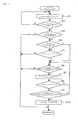
- stroke determination processing executed by the ECU 5 will be described with reference to the flow chart of Fig. 3 and the timing chart of Fig. 4. If counting down of a number of pulses of the crank pulsar rotor 2 is commenced by the ECU 5, "stroke determination processing" (main flow) shown in the flowchart of Fig. 3 is launched.
- step S1 if a crank pulse is detected, then in step S2 it is determined whether or not a crank reference position is being defined. With respect to the crank reference position, as shown in the timing chart of Fig. 4, if fifteen crank pulses are detected, since the non-toothed section of the crank pulsar rotor 2 must have passed by during this time, the position of the non-toothed section can be defined as the base (reference). Continuing on, in step S3, it is determined whether or not the stroke has been determined. Here, since the stroke is not yet determined, processing advances to step S4 and it is determined whether or not stroke determination is in progress.
- step S4 If it is determined in step S4 that stroke determination has not commenced, processing advances to step S5 and it is determined whether or not the stage count is N1.
- the value of N1 is a setting value for what stage count Pb pattern recognition starts from, and in this embodiment is set to "6". If it is determined in step S5 that the stage count is N1, processing advances to step S6 and it is determined whether or not there is a stroke determination possible state. In the event that it is determined in step S4 that stroke determination is in progress, since the determination of step S5, constituting a trigger for commencing stroke determination, has already been carried out, step S5 is skipped and processing advances to step S6.
- Fig. 5 shows step S6 within the flowchart of Fig. 3, and is a flowchart (sub flow 1) of processing for determining whether or not there is a stroke determination possible state. If step S6 is reached in the flowchart of Fig. 3, "stroke determination propriety determination" of Fig. 5 is launched. In step S61, it is determined whether or not there is a Pb detection fail state where detection of Pb is not possible due to damage to the Pb sensor or the like, and if it is determined that there is no Pb detection fail state processing advances to step S62.
- step S62 it is determined whether or not the engine rotation speed Ne is less than or equal to a reference engine rotation speed Ne0, being an upper limit value for engine rotation speed at which stroke determination is possible, and if it is determined to be less than or equal to Ne0 processing advances to step S63.
- step S63 it is determined whether or not throttle opening amount ⁇ Th is less than or equal to a reference throttle opening amount ⁇ Th0, being an upper limit value for throttle opening amount at which stroke determination is possible. If it is determined to be less than or equal to ⁇ Th0 in step S63, processing advances to step S64, it is determined that stroke determination is possible, "stroke determination propriety determination" is completed, and processing advances to step S7 of the main flow. In the event that processing advances to step S65, it is determined that stroke determination is not possible, and stroke determination is terminated with a return to the main flow.
- step S7 Pb pattern recognition processing is executed by the Pb pattern recognition section 505 within the ECU.
- Pb pattern recognition processing for recognizing a Pb pattern of combined intake pressure Pb in a specified stage count period as either "rising”, “upward peak” or "undetermined"
- Fig. 6 is a flowchart (sub flow 2) of Pb pattern recognition processing shown in step S7 of Fig. 3.
- Pb pattern recognition processing relating to a first embodiment of the present invention will be described.
- step S7 of Fig. 3 is reached, "Pb pattern recognition processing" of Fig. 6 is launched.
- Pb pattern recognition processing in order to recognize the Pb pattern, processing is carried out to recognize variation in combined intake pressure Pb every crank pulse generating period as a variation pattern.
- step S71 it is determined whether or not the stage count is six or more and eleven or less in a specified stage count period of this embodiment, and if the stage count is determined to be six or more and eleven or less processing advances to step S72.
- step S72 it is determined whether or not a value that is Pb0, being a previous detection value for combined intake pressure Pb, subtracted from Pb1, being the current detection value for combined intake pressure, is a specified value or greater. If it is determined that Pb1 - Pb0 is the specified value or greater, then in step S76 the variation pattern is determined to be increasing: upward (+1).
- step S72 processing advances to step S73 where it is determined whether or not Pb0 - Pb1 is a negative specified value or greater, and if Pb0 - Pb1 is determined to be the negative specified value or greater the variation pattern is determined to be reducing: downward (-1) in step S75.
- the variation pattern is determined to be no change (0).
- the specified value is a threshold value for determining whether or not there is change in the variation pattern, and is set taking into consideration the sensitivity of the Pb sensor.
- step S77 if the recognition results are accumulated using upward (+1), downward (-1) and no change (0), processing then advances to step S78, and it is determined whether or not a stage count value is eleven, which is a stage count for terminating Pb pattern recognition. If the stage count is determined to be eleven in step S78, processing advances to step S79. In the event that the stage count is not eleven, processing returns to step S71, and the recognition processing of steps S71 to S78 is repeated until the stage count reaches eleven.
- Pb pattern matching processing of steps S79 and later will be described with reference to Fig. 7.
- Fig. 7 is an example of a data map for Pb pattern recognition carried out in steps S79 and afterwards, and is stored in a Pb pattern map 506 (refer to Fig. 2).
- a signal pattern that has stored patterns for the stages 6 - 11 that are all upward (+1), corresponds to No. 0, and as shown in Fig. 7(b), the Pb pattern is determined to be "rising”.
- the stored patterns correspond to signal pattern No.s 1 - 9
- the Pb pattern is determined to be "upward peak”
- the patterns do not correspond to any of No.s 0 - 9 the Pb pattern is determined to be "undetermined”.
- step S81 if it is determined in step S79 that as a result of matching with the map the stored pattern is "rising”, processing advances to step S81 where the Pb pattern is defined as “rising”. Also, if it is determined in step S79 to be not “rising”, processing advances to step S80 where it is determined whether or not the stored pattern is "upward peak”. If it is determined to be "upward peak” in step S80, processing advances to step S82 where the Pb pattern is defined as "upward peak”. If it is determined to be not "upward peak” in step S80, processing advances to step S83 where the Pb pattern is defined as "undetermined".
- step S84 If the Pb pattern is defined as one of either “rising”, “upward peak” or “undetermined” as a result of the above described Pb pattern recognition processing, pattern recognition processing is terminated in step S84, and processing advances to step S8 of the main flow.
- a Pb pattern between stage count section between A - B are defined as “riding”, while a Pb pattern between C - D after one rotation of the crankshaft is defined as “upward peak”.
- the Pb pattern is repeatedly and alternately defined as “rising” and “upward peak” as long as there is no change in operating state of the engine 1, such as being determined to be in a stroke determination not possible state in the "stroke determination propriety determination" of Fig. 5.
- step S8 it is determined in step S8 whether or not the stage count is N2.
- the value of N2 is a setting value for what stage count Pb pattern recognition finishes at, and in this embodiment is set to "11". If it is determined in step 8 that the stage count is N2, processing advances to step S9 where it is determined whether or not the number of times recognition has been continuously performed for the Pb pattern has reached a specified number of times or greater. With this embodiment, the specified number of times is set to four times, and if pattern recognition is carried out a total of four times for a Pb pattern to yield "rising", "upward peak”, “rising”, “upward peak”, processing advances to step S10 where a stroke is defined. If stroke is defined in step S10, stroke determination processing is terminated.
- top dead center for the first to fourth cylinders is shown by the symbol # on the line representing pulse signal, but before stroke is defined by the stroke determination processing it is unclear which of the cylinder numbers inside the brackets (#) which has had crankshaft phase recognized at a 360 degree angle on both sides or the symbol # showing top dead center are correct.
- a Pb combined waveform generated during the same stage count values 6 - 11 is clearly different between the first rotation and the second rotation of the crankshaft, by identifying this as a Pb pattern of "rising” or "upward peak” it is made possible to carry out accurate stroke determination.
- selection of start stage count period and a completion stage count period for Pb pattern recognition avoids a non-toothed section of the crank pulsar rotor 2 for determining a reference position of the crankshaft, and takes into consideration stage count values which are not erroneously recognized as other Pb patterns, even if there is occurrence of slight delay in Pb detection time at times such as high speed operation of the engine.
- stage count values which are not erroneously recognized as other Pb patterns
- Pb pattern recognition processing is executed once step S7 in the flowchart of Fig. 3 is reached.
- Pb pattern recognition processing is executed once step S7 in the flowchart of Fig. 3 is reached.
- first of all combined intake pressure Pb measured at seven points from stage counts 6 to 11 are stored.
- the initial measured value is designated E point
- the final measured value is designated F point
- the maximum value is defined as G point while the minimum value is defined as H point.
- Fig. 9 and Fig. 10 are respectively a schematic explanatory drawing of another engine and intake pressure sensor suitable for use in the present invention, and a block diagram of a stroke determination unit suitable for use with this engine.
- Pb sensors 4a - 4d are provided in each of first to fourth cylinders.
- Fig. 9(b) among jet nozzles 14a - 14d connecting the intake pipes 11a - 11d and the capillaries 12a - 12d, only the jet nozzle 14d of the fourth cylinder has a smaller diameter than the rest, changing the sensitivity of the Pb sensor 4d.
- Fig. 10 is a block diagram of a stroke determination unit in the case where the engine Pb sensors have the above described structure.
- a Pb waveform-combining section 507 is added to the ECU5, as intake pressure change generating means.
- the Pb waveform combining section 507 is means for forming a waveform of combined intake pressure Pb from output values of the Pb sensors 4a - 4d, and with the structure of Fig. 9(a) the output values of three Pb sensors 4a - 4c are combined, while with the structure of Fig. 9(b) the output values of four Pb sensors 4a - 4d are combined, to form respective combined intake pressure waveforms.
Landscapes
- Engineering & Computer Science (AREA)
- Chemical & Material Sciences (AREA)
- Combustion & Propulsion (AREA)
- Mechanical Engineering (AREA)
- General Engineering & Computer Science (AREA)
- Combined Controls Of Internal Combustion Engines (AREA)
Abstract
Description
- The present invention relates to a stroke determination unit for a 4-cycle engine, and particularly to a stroke determination unit for a 4-cycle engine suitable for stroke determination of a multiple cylinder engine.
- With a conventional 4-cycle engine adopting an electronic fuel injection unit, stroke determination is performed based on both phase of an engine camshaft and phase of a crankshaft. In this regard, in
patent publication 1, a stroke determination unit is proposed that does not detect phase of a camshaft, but for a particular crankshaft phase compares intake pressure detected this time and intake pressure detected a period prior, and carries out stroke determination according to a magnitude relationship of the two. In this way, since it is not necessary to provide a sensor for detecting camshaft phase inside a cylinder head of the engine, it is possible to make the engine small and lightweight.
Patent Document 1:Japanese Patent Laid-open no. Hei. 10-227252 - However, with the technology of
patent document 1 described above, because stroke determination is carried out based on a magnitude relationship of measured intake pressures simply using an intake pressure sensor, in the case of taking into consideration a magnitude relationship for all intake pressures from low rotational speed region of an internal combustion engine to a high rotational speed region, setting takes a long time. Also, since there is comparison of magnitude values for a particular point, there is a problem that it is difficult to improve noise toughness with respect to the influence of interference such as noise on an electrical system. - The object of the present invention is to solve the above described problems of the related art, and to this end to provide, in a device for carrying out stroke detection with intake pressure as a parameter, a stroke determination unit for a 4-cycle engine in which stroke determination setting is simplified, and which is capable of improving noise toughness.
- In order to achieve the above described object, a first aspect of the present invention provides a stroke determination unit for a 4-cycle engine, comprising a multiple cylinder 4-cycle engine, crank angle detection means for detecting phase of a crank shaft, and intake pressure detection means for detecting intake pressure of cylinders provided with intake pressure variation generating means for causing variation so that an intake pressure waveform of at least one cylinder becomes different to intake pressure waveforms of other cylinders, intake pressure waveform combining means for combining detected intake pressure waveforms, pattern recognition means for recognizing a pattern of the detected intake pressure waveform, and stroke determination means for determining a stroke of each cylinder using the crankshaft phase and a recognized pattern.
- In a second aspect of the present invention, the pattern recognition means only recognizes a pattern in a specified crankshaft phase period.
- In a third aspect of the present invention, the specified crankshaft phase period is set so that an inflection point of the combined intake pressure waveform is close to a start time of the specified crankshaft phase period.
- In a fourth aspect of the present invention, the multiple cylinder engine is a regular interval detonation engine having expansion strokes at equal spacing, and the intake pressure variation generating means does not add an intake pressure waveform for a particular cylinder to an combined intake pressure waveform.
- According to a fifth aspect of the present invention, detection of intake pressure for the particular cylinder is not carried out, and fuel injection or ignition timing control is performed based on intake pressure detected for cylinders other than the particular cylinder.
- With a sixth aspect of the present invention, the intake pressure variation generating means changes sensitivity of intake pressure detection for a particular cylinder in the intake pressure detection means arranged for each cylinder.
- According to a seventh aspect of the invention, the pattern recognition means identifies fluctuation in combined intake pressure waveform for every crank pulse generation period as increase, decrease or change, and recognizes a pattern of the combined intake pressure waveform using the fluctuation result.
- According to an eighth aspect of the present invention, the pattern recognition means stores a plurality of intake pressure values including start time and end time of the specified crankshaft phase period, and recognizes a pattern of the combined intake pressure waveform from a relationship between the intake pressure values at the start time and the end time, and other intake pressure values within that range.
- According to the invention of
claim 1, setting the same pattern from a low rotational speed region to a high rotational speed region is easy because compared to a method where combined intake pressure values for particular phase of the crankshaft are compared, variation of an combined intake pressure waveform is recognized using a waveform pattern having continuity, and it is also possible to achieve accurate stroke determination processing with improved noise toughness. - According to the invention of
claim 2, since only a pattern of a particular period having a feature is recognized in an combined intake pressure waveform, it is possible to reduce load on a computer due to pattern recognition compared to a method that carries out recognition processing in all periods of the crankshaft. - According to the invention of
claim 3, since there is no straying of curved points of the combined intake pressure waveform appear to outside the specified crankshaft phase period, even if by some chance a delay arises at the time of intake negative pressure detection, in cases such as where the crankshaft is rotating at high speed, there is no erroneous pattern recognition, and it is possible to carry out accurate stroke determination. - According to the invention of
claim 4, even with an engine having regular interval detonation, it is possible to cause necessary variation for stroke determination in an intake pressure waveform without using a separate unit etc. - According to the invention of
claim 5, since it is not necessary to provide intake pressure detection means in a particular cylinder, it is possible to reduce the number of components and the manufacturing steps. - According to the invention of
claim 6, it is possible to cause variation in the intake pressure waveform without the addition of significant change to intake pressure detection means provided for every cylinder. - According to the invention of
claim 7, since pattern recognition is carried out using recognition results for three simple fluctuating patterns, in all engine operating states it is possible to carry out accurate stroke determination with improved pattern recognition precision. - According to the invention of
claim 8, since fluctuation in intake pressure measurement values that are caused to be estimated due to the occurrence of noise etc. are ignored, it is possible to improve noise toughness and carry out accurate stroke determination. -
- Fig. 1 is a schematic diagram of an engine and an intake pressure sensor suitable for application to the present invention.
- Fig. 2 is a block diagram of one embodiment of a stroke determination unit for an engine of the present invention.
- Fig. 3 is a flow chart showing a procedure for stroke determination processing.
- Fig. 4 is a timing chart showing a procedure for stroke determination processing.
- Fig. 5 is a flow chart showing a procedure for stroke determination propriety determination.
- Fig. 6 is a flowchart showing a procedure for Pb pattern recognition processing relating to a first embodiment of the present invention.
- Fig. 7 is a data map for Pb pattern recognition processing relating to the first embodiment of the present invention.
- Fig. 8 is a schematic diagram for Pb pattern recognition processing relating to a second embodiment of the present invention.
- Fig. 9 is a schematic diagram of another engine and an intake pressure sensor suitable for use in the present invention.
- Fig. 10 is a block diagram of another embodiment of a stroke determination unit for an engine of the present invention.
- A preferred embodiment of the present invention will be described in the following with reference to the drawings. Fig. 1 is a schematic diagram of a four-cycle four-cylinder engine and an intake pressure sensor suitable for use in the present invention. First to
fourth cylinders 10a - 10d of an engine are constructed so that one end of respectivelyseparate capillaries 12a - 12d communicates withrespective intake pipes 11a - 11d leading to intake ports. A Pb sensor (intake pressure sensor) 4, as intake pressure variation generating means, is constructed so as to detect combined intake pressure Pb, which is a combination of intake pressures P1, P2 and P3 generated in the first tothird intake pipes 11a - 11c, by merging the other ends of the first tothird capillaries 12a - 12c. Asecond Pb sensor 13 for measuring intake pressure P4 generated in theintake pipe 11d is connected to an end section of the capillary 12d of the fourth cylinder, but it is possible to omit this structure as long as it is possible to execute stroke determination on the basis of measurement values of the combined intake pressure Pb to carry out control for fuel injection and ignition timing. - The reason for having the structure as described above is that if a combined value of intake pressure for all cylinders generated in intake pipes of a regular interval detonation engine is measured, then in one cycle (that is, two rotations of the crankshaft) of the engine an intake pressure waveform will be the same for the first crankshaft rotation and the second crankshaft rotation, and so there is nothing that can be used for stroke determination.
- With the intake pressure variation generating means of this embodiment, since an intake pressure value for the fourth cylinder is excluded, as will be clear from subsequent description, variation is imparted to the combined intake pressure Pb waveform for the first and second rotations of the crankshaft and stroke determination is possible. In the case of a multiple cylinder engine where combustions intervals are different, since the intake pressure negative pressure waveform for each cycle is not periodic, it can be used as it is, or it is possible to impart variation to some cylinders or to impart new characteristics on the negative pressure waveform.
- Fig. 2 is a block diagram of one embodiment of a stroke determination unit suitable for use in the Pb sensor having the structure of Fig. 1. A pair of a
crank pulsar rotor 2 and apulse generator 3, for outputting 13 crank pulses per rotation and containing a non-toothed section, are provided on thecrankshaft 1a of theengine 1. 13 projections are arranged at intervals of 22.5 degrees, and an angle occupied by the non-toothed section is 90 degrees. Crank pulses and an output signal of thePb sensor 4 are input to theECU 5, together with other sensor signals and process signals. - The
ECU 5 is made up of aphase detection section 501, as crank angle detection means for detecting phase of the crankshaft based on the crank pulses, a stagecounter allocation section 502 for dividing one rotation of acrankshaft 1 by 13 at the output timing of the crank pulses and allocating stage numbers of "#1" to "#13" to respective phases (stages) of the crankshaft, a Pbpattern storage section 504 for storing variation patterns of the combined intake pressure Pb detected by thePb sensor 4, a Pbpattern recognition section 505 as pattern recognition means for recognizing a Pb pattern by referencing data held in aPb pattern map 506, and astroke determination section 503, as stroke determination means for determining stroke of theengine 1 based on stage count allocation results and Pb pattern recognition results. TheECU 5 controls aninjection 6 and anignition unit 7 based on output timing of the crank pulses and stroke determination results. - Next, stroke determination processing executed by the
ECU 5 will be described with reference to the flow chart of Fig. 3 and the timing chart of Fig. 4. If counting down of a number of pulses of thecrank pulsar rotor 2 is commenced by theECU 5, "stroke determination processing" (main flow) shown in the flowchart of Fig. 3 is launched. - In step S1, if a crank pulse is detected, then in step S2 it is determined whether or not a crank reference position is being defined. With respect to the crank reference position, as shown in the timing chart of Fig. 4, if fifteen crank pulses are detected, since the non-toothed section of the
crank pulsar rotor 2 must have passed by during this time, the position of the non-toothed section can be defined as the base (reference). Continuing on, in step S3, it is determined whether or not the stroke has been determined. Here, since the stroke is not yet determined, processing advances to step S4 and it is determined whether or not stroke determination is in progress. If it is determined in step S4 that stroke determination has not commenced, processing advances to step S5 and it is determined whether or not the stage count is N1. The value of N1 is a setting value for what stage count Pb pattern recognition starts from, and in this embodiment is set to "6". If it is determined in step S5 that the stage count is N1, processing advances to step S6 and it is determined whether or not there is a stroke determination possible state. In the event that it is determined in step S4 that stroke determination is in progress, since the determination of step S5, constituting a trigger for commencing stroke determination, has already been carried out, step S5 is skipped and processing advances to step S6. - Fig. 5 shows step S6 within the flowchart of Fig. 3, and is a flowchart (sub flow 1) of processing for determining whether or not there is a stroke determination possible state. If step S6 is reached in the flowchart of Fig. 3, "stroke determination propriety determination" of Fig. 5 is launched. In step S61, it is determined whether or not there is a Pb detection fail state where detection of Pb is not possible due to damage to the Pb sensor or the like, and if it is determined that there is no Pb detection fail state processing advances to step S62. In step S62, it is determined whether or not the engine rotation speed Ne is less than or equal to a reference engine rotation speed Ne0, being an upper limit value for engine rotation speed at which stroke determination is possible, and if it is determined to be less than or equal to Ne0 processing advances to step S63. In step S63, it is determined whether or not throttle opening amount θTh is less than or equal to a reference throttle opening amount θTh0, being an upper limit value for throttle opening amount at which stroke determination is possible. If it is determined to be less than or equal to θTh0 in step S63, processing advances to step S64, it is determined that stroke determination is possible, "stroke determination propriety determination" is completed, and processing advances to step S7 of the main flow. In the event that processing advances to step S65, it is determined that stroke determination is not possible, and stroke determination is terminated with a return to the main flow.
- Returning to Fig. 3, in step S7 Pb pattern recognition processing is executed by the Pb
pattern recognition section 505 within the ECU. In the following, description will be given of the details of Pb pattern recognition processing for recognizing a Pb pattern of combined intake pressure Pb in a specified stage count period as either "rising", "upward peak" or "undetermined" - Fig. 6 is a flowchart (sub flow 2) of Pb pattern recognition processing shown in step S7 of Fig. 3. In the flowchart, Pb pattern recognition processing relating to a first embodiment of the present invention will be described. If step S7 of Fig. 3 is reached, "Pb pattern recognition processing" of Fig. 6 is launched. With the Pb pattern recognition processing, in order to recognize the Pb pattern, processing is carried out to recognize variation in combined intake pressure Pb every crank pulse generating period as a variation pattern. In step S71, it is determined whether or not the stage count is six or more and eleven or less in a specified stage count period of this embodiment, and if the stage count is determined to be six or more and eleven or less processing advances to step S72. In step S72, it is determined whether or not a value that is Pb0, being a previous detection value for combined intake pressure Pb, subtracted from Pb1, being the current detection value for combined intake pressure, is a specified value or greater. If it is determined that Pb1 - Pb0 is the specified value or greater, then in step S76 the variation pattern is determined to be increasing: upward (+1). Also, if it is determined in step S72 that Pb1 - Pb0 is not the specified value or greater, processing advances to step S73 where it is determined whether or not Pb0 - Pb1 is a negative specified value or greater, and if Pb0 - Pb1 is determined to be the negative specified value or greater the variation pattern is determined to be reducing: downward (-1) in step S75.In the event that the determination in steps S72 and S73 are negative, in step S74 the variation pattern is determined to be no change (0). The specified value is a threshold value for determining whether or not there is change in the variation pattern, and is set taking into consideration the sensitivity of the Pb sensor.
- Continuing on, in step S77, if the recognition results are accumulated using upward (+1), downward (-1) and no change (0), processing then advances to step S78, and it is determined whether or not a stage count value is eleven, which is a stage count for terminating Pb pattern recognition. If the stage count is determined to be eleven in step S78, processing advances to step S79. In the event that the stage count is not eleven, processing returns to step S71, and the recognition processing of steps S71 to S78 is repeated until the stage count reaches eleven. Next, Pb pattern matching processing of steps S79 and later will be described with reference to Fig. 7.
- Fig. 7 is an example of a data map for Pb pattern recognition carried out in steps S79 and afterwards, and is stored in a Pb pattern map 506 (refer to Fig. 2). In Fig. 7(a), a signal pattern, that has stored patterns for the stages 6 - 11 that are all upward (+1), corresponds to No. 0, and as shown in Fig. 7(b), the Pb pattern is determined to be "rising". Besides that, if the stored patterns correspond to signal pattern No.s 1 - 9, the Pb pattern is determined to be "upward peak", while if the patterns do not correspond to any of No.s 0 - 9 the Pb pattern is determined to be "undetermined". Depending on the Pb pattern recognition, compared to a method that compares a combined intake pressure value in a particular phase of a crankshaft, since recognition is performed with a pattern having continuity noise toughness is improved, and it is possible to carry out accurate stroke determination processing.
- Returning to Fig. 6, if it is determined in step S79 that as a result of matching with the map the stored pattern is "rising", processing advances to step S81 where the Pb pattern is defined as "rising". Also, if it is determined in step S79 to be not "rising", processing advances to step S80 where it is determined whether or not the stored pattern is "upward peak". If it is determined to be "upward peak" in step S80, processing advances to step S82 where the Pb pattern is defined as "upward peak". If it is determined to be not "upward peak" in step S80, processing advances to step S83 where the Pb pattern is defined as "undetermined".
- If the Pb pattern is defined as one of either "rising", "upward peak" or "undetermined" as a result of the above described Pb pattern recognition processing, pattern recognition processing is terminated in step S84, and processing advances to step S8 of the main flow.
- As shown in the timing chart of Fig. 4, with this embodiment a Pb pattern between stage count section between A - B are defined as "riding", while a Pb pattern between C - D after one rotation of the crankshaft is defined as "upward peak". Continuing on after that, the Pb pattern is repeatedly and alternately defined as "rising" and "upward peak" as long as there is no change in operating state of the
engine 1, such as being determined to be in a stroke determination not possible state in the "stroke determination propriety determination" of Fig. 5. - Returning to Fig. 3, it is determined in step S8 whether or not the stage count is N2. The value of N2 is a setting value for what stage count Pb pattern recognition finishes at, and in this embodiment is set to "11". If it is determined in
step 8 that the stage count is N2, processing advances to step S9 where it is determined whether or not the number of times recognition has been continuously performed for the Pb pattern has reached a specified number of times or greater. With this embodiment, the specified number of times is set to four times, and if pattern recognition is carried out a total of four times for a Pb pattern to yield "rising", "upward peak", "rising", "upward peak", processing advances to step S10 where a stroke is defined. If stroke is defined in step S10, stroke determination processing is terminated. - In Fig. 4, top dead center for the first to fourth cylinders is shown by the symbol # on the line representing pulse signal, but before stroke is defined by the stroke determination processing it is unclear which of the cylinder numbers inside the brackets (#) which has had crankshaft phase recognized at a 360 degree angle on both sides or the symbol # showing top dead center are correct. However, with the present invention, noting that a Pb combined waveform generated during the same stage count values 6 - 11 is clearly different between the first rotation and the second rotation of the crankshaft, by identifying this as a Pb pattern of "rising" or "upward peak" it is made possible to carry out accurate stroke determination. Also, selection of start stage count period and a completion stage count period for Pb pattern recognition avoids a non-toothed section of the
crank pulsar rotor 2 for determining a reference position of the crankshaft, and takes into consideration stage count values which are not erroneously recognized as other Pb patterns, even if there is occurrence of slight delay in Pb detection time at times such as high speed operation of the engine. In Fig. 4, the fact that an inflection point E in the "upward peak" Pb pattern waveform is exhibited immediately after the Pb pattern recognition start stage count (6) is useful for period selection. - Referring to Fig. 8, a procedure for Pb pattern recognition processing relating to a second embodiment of the present invention will be described. Similarly to the first embodiment described above, Pb pattern recognition processing is executed once step S7 in the flowchart of Fig. 3 is reached. In this embodiment, first of all combined intake pressure Pb measured at seven points from stage counts 6 to 11 are stored. Next, from among measurement values for the seven measured points, the initial measured value is designated E point, the final measured value is designated F point, and among the 5 point remaining after removing the E point and F point, the maximum value is defined as G point while the minimum value is defined as H point. At this time, in the event that the "final measured value" is larger than the "initial measured value", and all "measurement values of the five remaining points" are between the "final measured value" and the "initial measured value", the Pb pattern is recognized as "rising". If this recognition condition is represented with an equation, it would become as follows:
if (F>E + 10mV) AND (G and H ≧ E - 10mV) AND (G and H ≦ F + 10mV)
The condition equation is stored in thePb pattern map 506 within theECU 5. Using the above-described method, with the example shown in Fig. 8, Fig. 8(a) is recognized as a "rising" Pb pattern. With the condition equation, the fact that 10 mV is being added or subtracted is to prevent erroneous recognition of a Pb pattern due to error of thePb sensor 4. - Next, Pb recognition for "upward peak" is carried out in the event that a "maximum value of the five remaining points" is larger than any of the "final measured value" and the "initial measured value", namely, represented as an equation, (G > E + 10mV) AND (G > F + 10mV). Using the above described method, with the example shown in Fig. 8, Fig. 8(b) and Fig. 8(c) are recognized as a "upward peak" Pb patterns.
- As a result of the above described pattern recognition, it becomes possible to prevent erroneous Pb pattern recognition even if contamination such as leakage due to noise in the electrical system etc. has slight influence on the Pb sensor output values. In this embodiment, if attention is paid to the waveform using the combined intake pressure shown in Fig. 8(a) and Fig. 8(b), the G point of Fig. 8(a) and the H point of Fig, 8(b) can be respectively speculated to be measurement values due to contamination such as noise. If data containing this type of noise is collated with a data table shown in Fig. 7 of the first embodiment, they will not correspond to any pattern, and there is a possibility of determining all Pb patterns to be "undetermined", but as a result of the Pb pattern recognition of this embodiment, since fluctuation in intake pressure measurement values speculated as being caused by noise etc. is made negligible, accurate stroke determination that is not affected by slight noise is made possible.
- Fig. 9 and Fig. 10 are respectively a schematic explanatory drawing of another engine and intake pressure sensor suitable for use in the present invention, and a block diagram of a stroke determination unit suitable for use with this engine. With this embodiment, as shown in Fig. 9(a),
Pb sensors 4a - 4d are provided in each of first to fourth cylinders. Also, as shown in Fig. 9(b), amongjet nozzles 14a - 14d connecting theintake pipes 11a - 11d and thecapillaries 12a - 12d, only thejet nozzle 14d of the fourth cylinder has a smaller diameter than the rest, changing the sensitivity of thePb sensor 4d. - Fig. 10 is a block diagram of a stroke determination unit in the case where the engine Pb sensors have the above described structure. A Pb waveform-combining
section 507 is added to the ECU5, as intake pressure change generating means. The Pbwaveform combining section 507 is means for forming a waveform of combined intake pressure Pb from output values of thePb sensors 4a - 4d, and with the structure of Fig. 9(a) the output values of threePb sensors 4a - 4c are combined, while with the structure of Fig. 9(b) the output values of fourPb sensors 4a - 4d are combined, to form respective combined intake pressure waveforms. - As has been described above, according to the present invention, since variation in an combined intake pressure waveform is recognized using a waveform pattern, noise toughness is improved and accurate stroke determination processing is made possible. Also, since only a pattern of a particular period having a feature is recognized in an combined intake pressure waveform, it is possible to reduce load on a computer due to pattern recognition compared to a method that carries out recognition processing in all periods of the crankshaft.
- With the above described embodiments, description has been given relating to application to a four-cycle multiple cylinder engine where all cylinders have regular interval detonation, but obviously it is also possible to apply to a four cycle multiple cylinder engine having irregular interval detonation.
-
- 1
- engine
- 1a
- crankshaft
- 2
- crank pulsar rotor
- 3
- pulse generator
- 4
- Pb sensor
- 5
- ECU
- 6
- injection
- 7
- ignition unit
- 501
- phase detection section
- 502
- stage count allocation section
- 503
- stroke determination section
- 504
- Pb pattern storage section
- 505
- Pb pattern recognition section
- 506
- Pb pattern map
- 507
- Pb waveform combining section
Claims (8)
- A stroke determination unit for a 4-cycle engine, having a multiple cylinder 4-cycle engine, crank angle detection means for detecting phase of a crank shaft (1a), and intake pressure detection means for detecting intake pressure of cylinders comprising:intake pressure variation generating means for causing variation so that an intake pressure waveform of at least one cylinder becomes different to intake pressure waveforms of other cylinders;intake pressure waveform combining means for combining detected intake pressure waveforms;pattern recognition means for recognizing a pattern of the detected intake pressure waveform; andstroke determination means for determining stroke of each cylinder using the crankshaft phase and a recognized pattern.
- The stroke determination unit for a 4-cycle engine as disclosed in claim 1, wherein the pattern recognition means only recognizes a pattern in a specified crankshaft phase period.
- The stroke determination unit for a 4-cycle engine as disclosed in any of the preceding claims, wherein the specified crankshaft phase period is set so that an inflection point of the combined intake pressure waveform is close to a start time of the specified crankshaft phase period.
- The stroke determination unit for a 4-cycle engine of any one of claim 1 to claim 3, wherein the multiple cylinder 4-cycle engine is an regular interval detonation engine having expansion strokes at equal spacing, and the intake pressure variation generating means does not add an intake pressure waveform for a particular cylinder to an combined intake pressure waveform.
- The stroke determination unit for a 4-cycle engine as disclosed in any of the preceding claims, wherein detection of intake pressure for the particular cylinder is not carried out, and fuel injection or ignition timing control is performed based on intake pressure detected for cylinders other than the particular cylinder.
- The stroke determination unit for a 4-cyclce engine as disclosed in any one of claim 1 to claim 5, wherein the intake pressure variation generating means changes sensitivity of intake pressure detection for a particular cylinder in the intake pressure detection means arranged for each cylinder.
- The stroke determination unit for a 4-cycle engine as disclosed in any one of claims 1 to 6, wherein the pattern recognition means identifies fluctuation in combined intake pressure waveform for every crank pulse generation period as increase, decrease or change, and recognizes a pattern of the combined intake pressure waveform using the fluctuation result.
- The stroke determination unit for a 4-cycle engine as disclosed in any one of claim 1 to 7, wherein the pattern recognition means stores a plurality of intake pressure values including start time and end time of the specified crankshaft phase period, and recognizes a pattern of the combined intake pressure waveform from a relationship between the intake pressure values at the start time and the end time, and other intake pressure values within that range.
Applications Claiming Priority (1)
| Application Number | Priority Date | Filing Date | Title |
|---|---|---|---|
| JP2005095600A JP4420348B2 (en) | 2005-03-29 | 2005-03-29 | 4-cycle engine stroke discrimination device |
Publications (2)
| Publication Number | Publication Date |
|---|---|
| EP1707937A1 true EP1707937A1 (en) | 2006-10-04 |
| EP1707937B1 EP1707937B1 (en) | 2012-08-22 |
Family
ID=36177653
Family Applications (1)
| Application Number | Title | Priority Date | Filing Date |
|---|---|---|---|
| EP06003836A Expired - Lifetime EP1707937B1 (en) | 2005-03-29 | 2006-02-24 | Stroke determination unit for 4-cycle engine |
Country Status (5)
| Country | Link |
|---|---|
| US (1) | US7194898B2 (en) |
| EP (1) | EP1707937B1 (en) |
| JP (1) | JP4420348B2 (en) |
| CA (1) | CA2537522C (en) |
| ES (1) | ES2390088T3 (en) |
Cited By (3)
| Publication number | Priority date | Publication date | Assignee | Title |
|---|---|---|---|---|
| FR2911919A1 (en) * | 2007-06-04 | 2008-08-01 | Siemens Vdo Automotive Sas | Internal combustion engine and crankshaft synchronizing method for vehicle, involves comparing space between positions of crankshaft to reference value, and deducing phase of motor based on comparison |
| GB2471890A (en) * | 2009-07-17 | 2011-01-19 | Gm Global Tech Operations Inc | Control unit for synchronizing fuel injection in an internal combustion engine |
| WO2013068367A1 (en) * | 2011-11-10 | 2013-05-16 | Continental Automotive Gmbh | Method for identifying cylinders in an internal combustion engine |
Families Citing this family (9)
| Publication number | Priority date | Publication date | Assignee | Title |
|---|---|---|---|---|
| JP4356892B2 (en) * | 2004-11-30 | 2009-11-04 | 本田技研工業株式会社 | Narrow-angle V-type 2-cylinder 4-stroke engine stroke discrimination device |
| JP4062309B2 (en) * | 2005-02-03 | 2008-03-19 | トヨタ自動車株式会社 | Control device for internal combustion engine |
| JP4825783B2 (en) * | 2007-12-07 | 2011-11-30 | 本田技研工業株式会社 | Engine control method |
| JP4825786B2 (en) * | 2007-12-20 | 2011-11-30 | 本田技研工業株式会社 | 4-cycle engine stroke discrimination device |
| JP5279644B2 (en) * | 2009-07-22 | 2013-09-04 | 株式会社ケーヒン | Control device for internal combustion engine |
| US8186331B2 (en) * | 2009-09-25 | 2012-05-29 | Cummins Power Generation Ip, Inc. | Spark suppression for a genset |
| DE102011083587B4 (en) * | 2011-09-28 | 2023-08-10 | Robert Bosch Gmbh | Method and device for monitoring at least one part of an internal combustion engine |
| US9279406B2 (en) * | 2012-06-22 | 2016-03-08 | Illinois Tool Works, Inc. | System and method for analyzing carbon build up in an engine |
| JP5552148B2 (en) * | 2012-09-28 | 2014-07-16 | 富士重工業株式会社 | Engine stroke discrimination device |
Citations (6)
| Publication number | Priority date | Publication date | Assignee | Title |
|---|---|---|---|---|
| US4889094A (en) * | 1986-04-04 | 1989-12-26 | Robert Bosch Gmbh | Method for recognizing the power stroke of a cylinder of an internal combustion engine |
| US5321979A (en) * | 1993-03-15 | 1994-06-21 | General Motors Corporation | Engine position detection using manifold pressure |
| US20010010218A1 (en) | 1997-02-13 | 2001-08-02 | Honda Giken Kogyo Kabushiki Kaisha | Stroke identifying unit of a four-stroke engine |
| US20020170346A1 (en) * | 2001-05-16 | 2002-11-21 | Akira Shimoyama | Stroke determination method of four cycle internal combustion engine and device thereof |
| WO2004013476A1 (en) * | 2002-07-31 | 2004-02-12 | Yamaha Hatsudoki Kabushiki Kaisha | Engine control device |
| EP1609975A2 (en) * | 2004-06-24 | 2005-12-28 | Yamaha Hatsudoki Kabushiki Kaisha | Internal combustion engine |
Family Cites Families (3)
| Publication number | Priority date | Publication date | Assignee | Title |
|---|---|---|---|---|
| JP4093682B2 (en) * | 1999-05-28 | 2008-06-04 | 本田技研工業株式会社 | 4-cycle engine stroke discrimination device |
| US6575136B1 (en) * | 1999-06-07 | 2003-06-10 | Keihin Corporation | Apparatus for detecting crank angle position in an internal combustion engine |
| JP4356892B2 (en) * | 2004-11-30 | 2009-11-04 | 本田技研工業株式会社 | Narrow-angle V-type 2-cylinder 4-stroke engine stroke discrimination device |
-
2005
- 2005-03-29 JP JP2005095600A patent/JP4420348B2/en not_active Expired - Fee Related
-
2006
- 2006-02-23 CA CA2537522A patent/CA2537522C/en not_active Expired - Fee Related
- 2006-02-24 EP EP06003836A patent/EP1707937B1/en not_active Expired - Lifetime
- 2006-02-24 ES ES06003836T patent/ES2390088T3/en not_active Expired - Lifetime
- 2006-03-24 US US11/389,324 patent/US7194898B2/en not_active Expired - Lifetime
Patent Citations (7)
| Publication number | Priority date | Publication date | Assignee | Title |
|---|---|---|---|---|
| US4889094A (en) * | 1986-04-04 | 1989-12-26 | Robert Bosch Gmbh | Method for recognizing the power stroke of a cylinder of an internal combustion engine |
| US5321979A (en) * | 1993-03-15 | 1994-06-21 | General Motors Corporation | Engine position detection using manifold pressure |
| US20010010218A1 (en) | 1997-02-13 | 2001-08-02 | Honda Giken Kogyo Kabushiki Kaisha | Stroke identifying unit of a four-stroke engine |
| US20020170346A1 (en) * | 2001-05-16 | 2002-11-21 | Akira Shimoyama | Stroke determination method of four cycle internal combustion engine and device thereof |
| WO2004013476A1 (en) * | 2002-07-31 | 2004-02-12 | Yamaha Hatsudoki Kabushiki Kaisha | Engine control device |
| EP1541845A1 (en) * | 2002-07-31 | 2005-06-15 | Yamaha Hatsudoki Kabushiki Kaisha | Engine control device |
| EP1609975A2 (en) * | 2004-06-24 | 2005-12-28 | Yamaha Hatsudoki Kabushiki Kaisha | Internal combustion engine |
Cited By (3)
| Publication number | Priority date | Publication date | Assignee | Title |
|---|---|---|---|---|
| FR2911919A1 (en) * | 2007-06-04 | 2008-08-01 | Siemens Vdo Automotive Sas | Internal combustion engine and crankshaft synchronizing method for vehicle, involves comparing space between positions of crankshaft to reference value, and deducing phase of motor based on comparison |
| GB2471890A (en) * | 2009-07-17 | 2011-01-19 | Gm Global Tech Operations Inc | Control unit for synchronizing fuel injection in an internal combustion engine |
| WO2013068367A1 (en) * | 2011-11-10 | 2013-05-16 | Continental Automotive Gmbh | Method for identifying cylinders in an internal combustion engine |
Also Published As
| Publication number | Publication date |
|---|---|
| JP4420348B2 (en) | 2010-02-24 |
| EP1707937B1 (en) | 2012-08-22 |
| JP2006274936A (en) | 2006-10-12 |
| ES2390088T3 (en) | 2012-11-06 |
| CA2537522A1 (en) | 2006-09-29 |
| US7194898B2 (en) | 2007-03-27 |
| CA2537522C (en) | 2011-01-18 |
| US20060218998A1 (en) | 2006-10-05 |
Similar Documents
| Publication | Publication Date | Title |
|---|---|---|
| EP1707937B1 (en) | Stroke determination unit for 4-cycle engine | |
| EP1918688B1 (en) | Misfire detecting apparatus for internal combustion engine | |
| JP3526870B2 (en) | Pattern recognition method and system for determining misfire condition in reciprocating engine | |
| JPS639679A (en) | Control of ignition timing of internal combustion engine | |
| CN102667122A (en) | Misfire detection device for internal combustion engine | |
| EP1878897B1 (en) | Reverse rotation detection apparatus and reverse rotation detection method for internal combustion engine | |
| CN102770653A (en) | Cylinder identifying of four-stroke cycle internal combustion engine | |
| US6496750B1 (en) | System and method for processing crank angle signals | |
| EP1736655B1 (en) | Misfire detection system for internal combustion engine | |
| US6334094B1 (en) | Engine speed calculation apparatus | |
| JP4356892B2 (en) | Narrow-angle V-type 2-cylinder 4-stroke engine stroke discrimination device | |
| EP0967379B1 (en) | Engine speed calculating apparatus | |
| US7921698B2 (en) | Method and system for detecting a crank angle of an engine | |
| CN103047022B (en) | A kind of electronic controlled diesel is without the starting method of camshaft signal and device | |
| JP4507201B2 (en) | Control device for multi-cylinder internal combustion engine | |
| JPH1030489A (en) | Cylinder determination method for internal combustion engine | |
| JPH08165950A (en) | Engine combustion condition detector | |
| JP4281037B2 (en) | Ignition device for internal combustion engine | |
| JP2007040208A (en) | Control device for internal combustion engine | |
| JP5737205B2 (en) | In-cylinder pressure sensor abnormality diagnosis device | |
| JPH10122026A (en) | Cylinder identification device | |
| CN119778089A (en) | Stroke determination device for four-stroke cycle single-cylinder engine | |
| JP3634137B2 (en) | Cylinder discrimination method and apparatus for internal combustion engine | |
| JP2005163726A (en) | Engine speed detection device and detection method | |
| JPH0413547B2 (en) |
Legal Events
| Date | Code | Title | Description |
|---|---|---|---|
| PUAI | Public reference made under article 153(3) epc to a published international application that has entered the european phase |
Free format text: ORIGINAL CODE: 0009012 |
|
| 17P | Request for examination filed |
Effective date: 20060224 |
|
| AK | Designated contracting states |
Kind code of ref document: A1 Designated state(s): AT BE BG CH CY CZ DE DK EE ES FI FR GB GR HU IE IS IT LI LT LU LV MC NL PL PT RO SE SI SK TR |
|
| AX | Request for extension of the european patent |
Extension state: AL BA HR MK YU |
|
| AKX | Designation fees paid |
Designated state(s): DE ES FR GB IT |
|
| 17Q | First examination report despatched |
Effective date: 20101021 |
|
| GRAP | Despatch of communication of intention to grant a patent |
Free format text: ORIGINAL CODE: EPIDOSNIGR1 |
|
| GRAS | Grant fee paid |
Free format text: ORIGINAL CODE: EPIDOSNIGR3 |
|
| GRAA | (expected) grant |
Free format text: ORIGINAL CODE: 0009210 |
|
| AK | Designated contracting states |
Kind code of ref document: B1 Designated state(s): DE ES FR GB IT |
|
| REG | Reference to a national code |
Ref country code: GB Ref legal event code: FG4D |
|
| REG | Reference to a national code |
Ref country code: DE Ref legal event code: R096 Ref document number: 602006031531 Country of ref document: DE Effective date: 20121018 |
|
| REG | Reference to a national code |
Ref country code: ES Ref legal event code: FG2A Ref document number: 2390088 Country of ref document: ES Kind code of ref document: T3 Effective date: 20121106 |
|
| PLBE | No opposition filed within time limit |
Free format text: ORIGINAL CODE: 0009261 |
|
| STAA | Information on the status of an ep patent application or granted ep patent |
Free format text: STATUS: NO OPPOSITION FILED WITHIN TIME LIMIT |
|
| 26N | No opposition filed |
Effective date: 20130523 |
|
| REG | Reference to a national code |
Ref country code: DE Ref legal event code: R097 Ref document number: 602006031531 Country of ref document: DE Effective date: 20130523 |
|
| REG | Reference to a national code |
Ref country code: DE Ref legal event code: R084 Ref document number: 602006031531 Country of ref document: DE |
|
| REG | Reference to a national code |
Ref country code: GB Ref legal event code: 746 Effective date: 20141114 |
|
| REG | Reference to a national code |
Ref country code: DE Ref legal event code: R084 Ref document number: 602006031531 Country of ref document: DE Effective date: 20141120 |
|
| REG | Reference to a national code |
Ref country code: FR Ref legal event code: PLFP Year of fee payment: 11 |
|
| REG | Reference to a national code |
Ref country code: FR Ref legal event code: PLFP Year of fee payment: 12 |
|
| REG | Reference to a national code |
Ref country code: FR Ref legal event code: PLFP Year of fee payment: 13 |
|
| PGFP | Annual fee paid to national office [announced via postgrant information from national office to epo] |
Ref country code: GB Payment date: 20180221 Year of fee payment: 13 Ref country code: ES Payment date: 20180301 Year of fee payment: 13 |
|
| PGFP | Annual fee paid to national office [announced via postgrant information from national office to epo] |
Ref country code: IT Payment date: 20180221 Year of fee payment: 13 Ref country code: FR Payment date: 20180111 Year of fee payment: 13 |
|
| PGFP | Annual fee paid to national office [announced via postgrant information from national office to epo] |
Ref country code: DE Payment date: 20190212 Year of fee payment: 14 |
|
| GBPC | Gb: european patent ceased through non-payment of renewal fee |
Effective date: 20190224 |
|
| PG25 | Lapsed in a contracting state [announced via postgrant information from national office to epo] |
Ref country code: GB Free format text: LAPSE BECAUSE OF NON-PAYMENT OF DUE FEES Effective date: 20190224 |
|
| PG25 | Lapsed in a contracting state [announced via postgrant information from national office to epo] |
Ref country code: IT Free format text: LAPSE BECAUSE OF NON-PAYMENT OF DUE FEES Effective date: 20190224 Ref country code: FR Free format text: LAPSE BECAUSE OF NON-PAYMENT OF DUE FEES Effective date: 20190228 |
|
| REG | Reference to a national code |
Ref country code: ES Ref legal event code: FD2A Effective date: 20200331 |
|
| PG25 | Lapsed in a contracting state [announced via postgrant information from national office to epo] |
Ref country code: ES Free format text: LAPSE BECAUSE OF NON-PAYMENT OF DUE FEES Effective date: 20190225 |
|
| REG | Reference to a national code |
Ref country code: DE Ref legal event code: R119 Ref document number: 602006031531 Country of ref document: DE |
|
| PG25 | Lapsed in a contracting state [announced via postgrant information from national office to epo] |
Ref country code: DE Free format text: LAPSE BECAUSE OF NON-PAYMENT OF DUE FEES Effective date: 20200901 |