EP1707800A1 - Fuel injection valve - Google Patents
Fuel injection valve Download PDFInfo
- Publication number
- EP1707800A1 EP1707800A1 EP05703944A EP05703944A EP1707800A1 EP 1707800 A1 EP1707800 A1 EP 1707800A1 EP 05703944 A EP05703944 A EP 05703944A EP 05703944 A EP05703944 A EP 05703944A EP 1707800 A1 EP1707800 A1 EP 1707800A1
- Authority
- EP
- European Patent Office
- Prior art keywords
- fuel injection
- nozzle
- injection valve
- coating layer
- nozzle needle
- Prior art date
- Legal status (The legal status is an assumption and is not a legal conclusion. Google has not performed a legal analysis and makes no representation as to the accuracy of the status listed.)
- Withdrawn
Links
- 239000000446 fuel Substances 0.000 title claims abstract description 73
- 238000002347 injection Methods 0.000 title claims abstract description 57
- 239000007924 injection Substances 0.000 title claims abstract description 57
- 239000011247 coating layer Substances 0.000 claims abstract description 28
- 239000010409 thin film Substances 0.000 claims description 5
- 238000007740 vapor deposition Methods 0.000 claims description 3
- 229910003481 amorphous carbon Inorganic materials 0.000 claims description 2
- 239000010408 film Substances 0.000 claims description 2
- 238000002485 combustion reaction Methods 0.000 description 5
- PXHVJJICTQNCMI-UHFFFAOYSA-N Nickel Chemical compound [Ni] PXHVJJICTQNCMI-UHFFFAOYSA-N 0.000 description 4
- 229910000831 Steel Inorganic materials 0.000 description 4
- 239000010959 steel Substances 0.000 description 4
- VYZAMTAEIAYCRO-UHFFFAOYSA-N Chromium Chemical compound [Cr] VYZAMTAEIAYCRO-UHFFFAOYSA-N 0.000 description 2
- ZOKXTWBITQBERF-UHFFFAOYSA-N Molybdenum Chemical compound [Mo] ZOKXTWBITQBERF-UHFFFAOYSA-N 0.000 description 2
- 230000003116 impacting effect Effects 0.000 description 2
- 239000000463 material Substances 0.000 description 2
- 229910052750 molybdenum Inorganic materials 0.000 description 2
- 239000011733 molybdenum Substances 0.000 description 2
- 229910052759 nickel Inorganic materials 0.000 description 2
- 238000012360 testing method Methods 0.000 description 2
- OKTJSMMVPCPJKN-UHFFFAOYSA-N Carbon Chemical compound [C] OKTJSMMVPCPJKN-UHFFFAOYSA-N 0.000 description 1
- 229910052799 carbon Inorganic materials 0.000 description 1
- 238000004891 communication Methods 0.000 description 1
- 230000007423 decrease Effects 0.000 description 1
- 230000000977 initiatory effect Effects 0.000 description 1
- 238000005259 measurement Methods 0.000 description 1
- 238000000034 method Methods 0.000 description 1
- 239000007921 spray Substances 0.000 description 1
Images



Classifications
-
- F—MECHANICAL ENGINEERING; LIGHTING; HEATING; WEAPONS; BLASTING
- F02—COMBUSTION ENGINES; HOT-GAS OR COMBUSTION-PRODUCT ENGINE PLANTS
- F02M—SUPPLYING COMBUSTION ENGINES IN GENERAL WITH COMBUSTIBLE MIXTURES OR CONSTITUENTS THEREOF
- F02M61/00—Fuel-injectors not provided for in groups F02M39/00 - F02M57/00 or F02M67/00
- F02M61/16—Details not provided for in, or of interest apart from, the apparatus of groups F02M61/02 - F02M61/14
- F02M61/166—Selection of particular materials
-
- F—MECHANICAL ENGINEERING; LIGHTING; HEATING; WEAPONS; BLASTING
- F02—COMBUSTION ENGINES; HOT-GAS OR COMBUSTION-PRODUCT ENGINE PLANTS
- F02M—SUPPLYING COMBUSTION ENGINES IN GENERAL WITH COMBUSTIBLE MIXTURES OR CONSTITUENTS THEREOF
- F02M61/00—Fuel-injectors not provided for in groups F02M39/00 - F02M57/00 or F02M67/00
- F02M61/16—Details not provided for in, or of interest apart from, the apparatus of groups F02M61/02 - F02M61/14
-
- F—MECHANICAL ENGINEERING; LIGHTING; HEATING; WEAPONS; BLASTING
- F02—COMBUSTION ENGINES; HOT-GAS OR COMBUSTION-PRODUCT ENGINE PLANTS
- F02M—SUPPLYING COMBUSTION ENGINES IN GENERAL WITH COMBUSTIBLE MIXTURES OR CONSTITUENTS THEREOF
- F02M61/00—Fuel-injectors not provided for in groups F02M39/00 - F02M57/00 or F02M67/00
- F02M61/16—Details not provided for in, or of interest apart from, the apparatus of groups F02M61/02 - F02M61/14
- F02M61/18—Injection nozzles, e.g. having valve seats; Details of valve member seated ends, not otherwise provided for
-
- F—MECHANICAL ENGINEERING; LIGHTING; HEATING; WEAPONS; BLASTING
- F02—COMBUSTION ENGINES; HOT-GAS OR COMBUSTION-PRODUCT ENGINE PLANTS
- F02M—SUPPLYING COMBUSTION ENGINES IN GENERAL WITH COMBUSTIBLE MIXTURES OR CONSTITUENTS THEREOF
- F02M2200/00—Details of fuel-injection apparatus, not otherwise provided for
- F02M2200/90—Selection of particular materials
-
- F—MECHANICAL ENGINEERING; LIGHTING; HEATING; WEAPONS; BLASTING
- F02—COMBUSTION ENGINES; HOT-GAS OR COMBUSTION-PRODUCT ENGINE PLANTS
- F02M—SUPPLYING COMBUSTION ENGINES IN GENERAL WITH COMBUSTIBLE MIXTURES OR CONSTITUENTS THEREOF
- F02M2200/00—Details of fuel-injection apparatus, not otherwise provided for
- F02M2200/90—Selection of particular materials
- F02M2200/9038—Coatings
-
- F—MECHANICAL ENGINEERING; LIGHTING; HEATING; WEAPONS; BLASTING
- F02—COMBUSTION ENGINES; HOT-GAS OR COMBUSTION-PRODUCT ENGINE PLANTS
- F02M—SUPPLYING COMBUSTION ENGINES IN GENERAL WITH COMBUSTIBLE MIXTURES OR CONSTITUENTS THEREOF
- F02M2547/00—Special features for fuel-injection valves actuated by fluid pressure
- F02M2547/003—Valve inserts containing control chamber and valve piston
-
- F—MECHANICAL ENGINEERING; LIGHTING; HEATING; WEAPONS; BLASTING
- F02—COMBUSTION ENGINES; HOT-GAS OR COMBUSTION-PRODUCT ENGINE PLANTS
- F02M—SUPPLYING COMBUSTION ENGINES IN GENERAL WITH COMBUSTIBLE MIXTURES OR CONSTITUENTS THEREOF
- F02M2547/00—Special features for fuel-injection valves actuated by fluid pressure
- F02M2547/006—Springs assisting hydraulic closing force
-
- F—MECHANICAL ENGINEERING; LIGHTING; HEATING; WEAPONS; BLASTING
- F02—COMBUSTION ENGINES; HOT-GAS OR COMBUSTION-PRODUCT ENGINE PLANTS
- F02M—SUPPLYING COMBUSTION ENGINES IN GENERAL WITH COMBUSTIBLE MIXTURES OR CONSTITUENTS THEREOF
- F02M47/00—Fuel-injection apparatus operated cyclically with fuel-injection valves actuated by fluid pressure
- F02M47/02—Fuel-injection apparatus operated cyclically with fuel-injection valves actuated by fluid pressure of accumulator-injector type, i.e. having fuel pressure of accumulator tending to open, and fuel pressure in other chamber tending to close, injection valves and having means for periodically releasing that closing pressure
- F02M47/027—Electrically actuated valves draining the chamber to release the closing pressure
Definitions
- the present invention relates to a fuel injection valve for injecting fuel into the cylinders of an internal combustion engine.
- This fuel injection valve for injecting fuel into an internal combustion engine, there is publicly known a type of fuel injection valve disclosed in, for example, Japanese Unexamined Patent Application Publication No. Hei 7-310621 .
- This fuel injection valve is for directly injecting fuel into the cylinders of an internal combustion engine, and comprises a control chamber in the body of the injection valve that is connected to a fuel low-pressure section by energizing an electromagnetic actuator, which, by removing the valve piston back pressure, raises the nozzle needle to thereby start fuel injection.
- the energizing of the electromagnetic actuator is stopped, breaking the connection state between the control chamber and the fuel low-pressure section, whereby a prescribed back pressure acts on the valve piston, pushing down the nozzle needle and thereby terminating the fuel injection.
- initiation and termination of fuel injection are carried out by controlling the back pressure of the valve piston to use the nozzle needle to close and open the nozzle hole in the nozzle body.
- a material that has a high hardness is selected as the material of the nozzle needle to reduce nozzle needle wear and deformation and obtain stable fuel injection characteristics over an extended period of time.
- An object of the present invention is to provide a fuel injection valve that overcomes the above problems of the prior art.
- An object of the present invention is to provide a fuel injection valve that can effectively suppress wear of the seat portion of the nozzle body caused by the nozzle needle seating on the nozzle body.
- the present invention effectively suppresses wear on the seat portion by keeping down that frictional resistance.
- a fuel injection valve having a nozzle body with a nozzle hole(s) at its tip that is opened and closed by a nozzle needle housed in the nozzle body, a fuel injection valve is provided that is characterized in that an area of contact between the nozzle needle and a seat on the nozzle body is provided with a coating layer to reduce the frictional resistance with the nozzle body.
- the coating layer may be provided by applying a C2 coat to the tip of the nozzle needle, or by providing a DLC thin film.
- Figure 1 shows a sectional view of an embodiment of the fuel injection valve according to this invention.
- Reference symbol 1 denotes a fuel injection valve used in a common rail system for the injected supply of fuel in a diesel internal combustion engine.
- the fuel injection valve 1 is attached to the cylinder of a diesel internal combustion engine (not shown) to directly inject into the cylinder at a prescribed timing a prescribed amount of high-pressure fuel supplied from a common rail that is not shown.
- a nozzle 3 is affixed to the tip of a nozzle holder 2 by a retaining nut 4.
- An electromagnetic actuator 5 is provided at the rear end of the nozzle holder 2.
- the nozzle holder 2 has an injector housing 22 with a guide hole 21 formed in the axial direction thereof; inside the guide hole 21 is a valve piston 23 that can move axially by means of the guide hole 21.
- a spring 25 is housed in a spring chamber 29 of the injector housing 22; the spring 25 urges a nozzle needle 32, described later, in the direction of a nozzle hole 35.
- Reference symbol 26 denotes a passage provided in the injector housing 22 for feeding high-pressure fuel from the common rail (not shown) to the nozzle 3.
- the nozzle 3 has a nozzle body 31 and the nozzle needle 32, with the nozzle needle 32 being housed in the nozzle body 31 to be axially movably supported and guided thereby by means of a hole 33 formed coaxially in the nozzle body 31.
- a tip portion 32A of the nozzle needle 32 extends within a cylinder portion 34 provided in the nozzle body 31 in alignment with the hole 33, forming a configuration in which the tip of the nozzle needle 32 functions as a valve element that opens and closes the nozzle hole 35.
- a fuel reservoir 37 formed in the nozzle body 31 is a fuel reservoir 37 in which high-pressure fuel from the passage 26, guided via a passage 36, collects.
- a tapered portion 38 is formed on the nozzle needle 32 to enable the pressure of the high-pressure fuel in the fuel reservoir 37 to act as a force that pushes the nozzle needle 32 away from the nozzle hole 35.
- valve body 24 Housed at the rear end of the injector housing 22 is a valve body 24 comprising a drive mechanism for driving the nozzle 3 in association with the valve piston 23.
- the valve body 24 is integrally formed by a lower cylindrical portion 24A and an upper flange portion 24B, and is contained in a hole portion 27 for housing the valve body 24 provided at the rear end of the injector housing 22.
- the hole portion 27 is formed in a shape that approximately corresponds to the outside shape of the valve body 24; the bottom of the hole portion 27 connects to the guide hole 21 into which the valve piston 23 is inserted until the upper end 23A of the valve piston 23 is in the lower cylindrical portion 24A. There is an oil-tight state between the outside surface of the valve piston 23 and the inside surface of the lower cylindrical portion 24A.
- a nut 28 is screwed into the opening portion of the hole portion 27 to fix the valve body 24 at the prescribed position in the hole portion 27.
- a thread 28a formed on the outside surface of the nut 28 engages with a thread 27a on the inside surface of the opening portion of the hole portion 27, and the valve body 24 is affixed to the injector housing 22 by tightening the nut 28 towards the valve body 24.
- valve piston 23 and valve body 24 are assembled into the injector housing 22.
- a drain chamber 41 At the rear end of the injector housing 22, there are formed a drain chamber 41, a radial supply passage 43 and an axial drain passage 44 that communicates with a control chamber 45.
- the supply passage 43 communicates with an intake fitting 47 via a radial guide passage 46 inside the injector housing 22; the bottom of the control chamber 45 is formed by the top surface of the valve piston 23.
- a ball 52 Affixed to the armature bolt 51 of the electromagnetic actuator 5 is a ball 52 functioning as a valve element that constitutes a valve mechanism controlling the state of communication between the control chamber 45 and the fuel low-pressure section.
- the armature bolt 51 is urged towards the drain passage 44 by the force of a valve spring (not shown), whereby the drain passage 44 is closed by the ball 52 being pressed against the end opening of the drain passage 44.
- the end opening of the drain passage 44 is closed by the ball 52, whereby the control chamber 45 is filled with high-pressure fuel, so that by means of the valve piston 23, the nozzle hole 35 is closed by the nozzle needle 32, so fuel injection does not take place.
- the ball 52 separates from the end opening of the drain passage 44, whereby high-pressure fuel in the control chamber 45 escapes to the fuel low-pressure section, so the pressure in the control chamber 45 decreases and fuel injection takes place.
- the nozzle needle 32 again closes the nozzle hole 35, terminating the fuel injection.
- FIG 2 is an enlarged detailed view of the nozzle 3 of Figure 1.
- the nozzle needle 32 is guidably supported in the hole 33 of the nozzle body 31 by the large-diameter portion 32A thereof.
- the tip 32B of the nozzle needle 32 closes the nozzle hole 35 by seating on the seat 31A formed on the inside of the nozzle body 31 by the nozzle hole 35, thereby closing the fuel injection valve.
- the fuel injection valve is opened by lifting the nozzle needle 32, which separates the tip 32B from the seat 31A.
- a coating layer Y is provided on the area of contact between the nozzle needle 32 and the seat 31A to reduce the frictional resistance with the nozzle body 31 (that is, with the seat 31A).
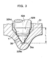
- the coating layer Y is provided within the surface range indicated in Figure 3 by the symbol L; that is, from the projecting portion 32Ba at the tip 32B to the portion 32Aa at which the large-diameter portion 32A ends.
- the coating layer Y is provided over the entire tip of the nozzle needle 32, including the area of contact with the seat 31 A.
- the coating layer Y may be provided over the entire surface of the nozzle needle 32.
- the coating layer Y is a hard, amorphous carbon film such as a DLC (Diamond-Like Carbon) thin film fabricated by the ionization vapor deposition method.
- a DLC thin film has good surface smoothness with a coefficient of friction in the order of 0.1.
- nickel chrome molybdenum steel (SNCM) is usually used for the nozzle body 31 and high-speed machine steel (SKH) for the nozzle needle 32, and these have a coefficient of friction in the order of 0.35 to 0.40. Therefore, providing the tip 32B of the nozzle needle 32 with the coating layer Y enables the frictional resistance between the tip 32B and the seat 31A to be reduced to one-third or less than in the prior art. As a result, wear of the seat 31A when the tip 32B of the nozzle needle 32 seats on the seat 31 A of the nozzle body 31 can be reduced, making it possible to keep down changes over time in the fuel injection characteristics of the fuel injection valve 1.
- the coating layer Y it is desirable for the coating layer Y to be formed with a thickness of 0.1 ⁇ m to 30 ⁇ m. From the standpoint of adhesion and wear resistance, a thickness of from 1 ⁇ m to 5 ⁇ m is more preferable.
- the coefficient of friction between the coating layer Y and the nozzle body 31 is preferably not more than 0.2, and from the standpoint of wear resistance, is more preferably not more than 0.1.
- the coating layer Y should have a Vickers hardness of not less than 2000.
- the coating layer Y is provided on the nozzle needle 32 as described in the above, when the fuel injection valve 1 closes, between the time from when the tip of the nozzle needle 32 contacts the seat 31 A of the nozzle body 31 to when the tip of the nozzle needle 32 is pressed against the seat 31A of the nozzle body 31, the tip of the nozzle needle 32 slides on the seat 31 A in a state of low frictional resistance. Therefore, wear on the seat 31A arising when the valve is closed can be reduced compared to when the coating layer Y is not provided. As a result, the fuel injection valve 1 can be operated over an extended period of time with the required fuel injection characteristics.
- Ionization vapor deposition was used to form the coating layer Y as a DLC thin film on the tip 32B, as shown in Figure 3.
- the coating layer Y had a thickness of 4 ⁇ m, and coefficient of friction between the coating layer Y and the nozzle body 31 was 0.1.
- the amount of wear on the seat 31A and changes over time in the injection amount of the fuel injection valve 1 were measured.
- the horizontal axis is test time (hr) and the vertical axis is relative wear.
- the relative wear is the ratio used with respect to 1 taken as the maximum value of wear obtained after testing a conventional nozzle body.
- the fuel injection valve according to this invention is useful for improving fuel injection valves, being able to keep down changes over time in the fuel injection characteristics of the fuel injection valve.
Landscapes
- Engineering & Computer Science (AREA)
- Chemical & Material Sciences (AREA)
- Combustion & Propulsion (AREA)
- Mechanical Engineering (AREA)
- General Engineering & Computer Science (AREA)
- Fuel-Injection Apparatus (AREA)
Abstract
In a fuel injection valve (1) having a nozzle body (31) with a nozzle hole (35) at its tip that is opened and closed by a nozzle needle (32) housed in the nozzle body (31), the area of contact between the nozzle needle (32) and a seat (31A) on the nozzle body (31) is provided with a coating layer (Y) to reduce the frictional resistance with the nozzle body (31). When the nozzle needle (32) seats on the seat (31A), between the time from when the tip of the nozzle needle (32) contacts the seat (31 A) to when it is pressed against the seat (31A), the nozzle needle (32) slides on the surface of the nozzle body (31) with low frictional resistance. As a result, wear on the seat (31A) when the nozzle needle (32) is seated to open the valve can be kept down.
Description
- The present invention relates to a fuel injection valve for injecting fuel into the cylinders of an internal combustion engine.
- As a fuel injection valve for injecting fuel into an internal combustion engine, there is publicly known a type of fuel injection valve disclosed in, for example,
Japanese Unexamined Patent Application Publication No. Hei 7-310621 - In this way, initiation and termination of fuel injection are carried out by controlling the back pressure of the valve piston to use the nozzle needle to close and open the nozzle hole in the nozzle body. Thus, there is a problem of the repeated impact of the nozzle needle on the nozzle body causing wear on the nozzle needle and the nozzle body which, over time, changes the fuel injection characteristics of the fuel injection valve.
- To resolve this problem, in the prior art, a material that has a high hardness is selected as the material of the nozzle needle to reduce nozzle needle wear and deformation and obtain stable fuel injection characteristics over an extended period of time.
- However, even if wear on the nozzle needle is reduced by increasing the hardness of the nozzle needle, the initial hardness cannot be maintained since the hardness of the nozzle body is reduced by heat, so wear of the nozzle body arises due to the nozzle needle impacting against the nozzle body during valve close operations. As a result, the wear on the nozzle body increases with the passing of time, gradually changing the nozzle needle seating position, altering the fuel injection characteristics, thereby making it impossible to obtain stable fuel injection characteristics over an extended period of time.
- An object of the present invention is to provide a fuel injection valve that overcomes the above problems of the prior art.
- An object of the present invention is to provide a fuel injection valve that can effectively suppress wear of the seat portion of the nozzle body caused by the nozzle needle seating on the nozzle body.
- To resolve the above problems, focusing on the frictional resistance between the nozzle needle and the nozzle body seat when the nozzle needle seats on the nozzle body seat portion, the present invention effectively suppresses wear on the seat portion by keeping down that frictional resistance.
- In accordance with the present invention, in a fuel injection valve having a nozzle body with a nozzle hole(s) at its tip that is opened and closed by a nozzle needle housed in the nozzle body, a fuel injection valve is provided that is characterized in that an area of contact between the nozzle needle and a seat on the nozzle body is provided with a coating layer to reduce the frictional resistance with the nozzle body.
- The coating layer may be provided by applying a C2 coat to the tip of the nozzle needle, or by providing a DLC thin film. By thus providing a coating layer, when the nozzle needle seats on the seat portion in the nozzle body, during the period from when the nozzle needle contacts the seat portion to when it presses against the seat portion, the nozzle needle slides on the surface of the nozzle body with a small frictional resistance. As a result, it is possible to keep down wear of the seat portion when the nozzle needle is seated to open the valve.
-
- Figure 1 is a sectional view of an embodiment of this invention.
- Figure 2 is an enlarged view showing details of the nozzle portion of Figure 1.
- Figure 3 is an enlarged sectional view of an essential portion of Figure 2.
- Figure 4 is a graph showing the measured wear ratio in the case of the embodiment, together with the measured wear ratio in the case of a fuel injection valve of the prior art.
- The invention will now be described in further detail, with reference to the appended drawings.
- Figure 1 shows a sectional view of an embodiment of the fuel injection valve according to this invention. Reference symbol 1 denotes a fuel injection valve used in a common rail system for the injected supply of fuel in a diesel internal combustion engine. The fuel injection valve 1 is attached to the cylinder of a diesel internal combustion engine (not shown) to directly inject into the cylinder at a prescribed timing a prescribed amount of high-pressure fuel supplied from a common rail that is not shown. A
nozzle 3 is affixed to the tip of anozzle holder 2 by aretaining nut 4. Anelectromagnetic actuator 5 is provided at the rear end of thenozzle holder 2. - The
nozzle holder 2 has aninjector housing 22 with aguide hole 21 formed in the axial direction thereof; inside theguide hole 21 is avalve piston 23 that can move axially by means of theguide hole 21. Aspring 25 is housed in aspring chamber 29 of theinjector housing 22; thespring 25 urges anozzle needle 32, described later, in the direction of anozzle hole 35.Reference symbol 26 denotes a passage provided in theinjector housing 22 for feeding high-pressure fuel from the common rail (not shown) to the nozzle 3.Thenozzle 3 has anozzle body 31 and thenozzle needle 32, with thenozzle needle 32 being housed in thenozzle body 31 to be axially movably supported and guided thereby by means of ahole 33 formed coaxially in thenozzle body 31. Atip portion 32A of thenozzle needle 32 extends within acylinder portion 34 provided in thenozzle body 31 in alignment with thehole 33, forming a configuration in which the tip of thenozzle needle 32 functions as a valve element that opens and closes thenozzle hole 35. - Thus, when the
nozzle needle 32 is held in a position in which it closes thenozzle hole 35, fuel is not sprayed from the fuel injection valve 1. On the other hand, when thenozzle needle 32 is retracted, opening thenozzle hole 35, and thenozzle needle 32 is maintained in that position, fuel sprays from the fuel injection valve 1. - Formed in the
nozzle body 31 is afuel reservoir 37 in which high-pressure fuel from thepassage 26, guided via apassage 36, collects. On the other hand, atapered portion 38 is formed on thenozzle needle 32 to enable the pressure of the high-pressure fuel in thefuel reservoir 37 to act as a force that pushes thenozzle needle 32 away from thenozzle hole 35. - Housed at the rear end of the
injector housing 22 is avalve body 24 comprising a drive mechanism for driving thenozzle 3 in association with thevalve piston 23. Thevalve body 24 is integrally formed by a lowercylindrical portion 24A and anupper flange portion 24B, and is contained in ahole portion 27 for housing thevalve body 24 provided at the rear end of theinjector housing 22. - The
hole portion 27 is formed in a shape that approximately corresponds to the outside shape of thevalve body 24; the bottom of thehole portion 27 connects to theguide hole 21 into which thevalve piston 23 is inserted until theupper end 23A of thevalve piston 23 is in the lowercylindrical portion 24A. There is an oil-tight state between the outside surface of thevalve piston 23 and the inside surface of the lowercylindrical portion 24A. - A
nut 28 is screwed into the opening portion of thehole portion 27 to fix thevalve body 24 at the prescribed position in thehole portion 27. A thread 28a formed on the outside surface of thenut 28 engages with a thread 27a on the inside surface of the opening portion of thehole portion 27, and thevalve body 24 is affixed to theinjector housing 22 by tightening thenut 28 towards thevalve body 24. - As described above, the
valve piston 23 andvalve body 24 are assembled into theinjector housing 22. At the rear end of theinjector housing 22, there are formed adrain chamber 41, aradial supply passage 43 and anaxial drain passage 44 that communicates with acontrol chamber 45. Thesupply passage 43 communicates with an intake fitting 47 via aradial guide passage 46 inside theinjector housing 22; the bottom of thecontrol chamber 45 is formed by the top surface of thevalve piston 23. - Affixed to the
armature bolt 51 of theelectromagnetic actuator 5 is aball 52 functioning as a valve element that constitutes a valve mechanism controlling the state of communication between thecontrol chamber 45 and the fuel low-pressure section. Thearmature bolt 51 is urged towards thedrain passage 44 by the force of a valve spring (not shown), whereby thedrain passage 44 is closed by theball 52 being pressed against the end opening of thedrain passage 44. - Therefore, when the
electromagnetic actuator 5 is not being energized, the end opening of thedrain passage 44 is closed by theball 52, whereby thecontrol chamber 45 is filled with high-pressure fuel, so that by means of thevalve piston 23, thenozzle hole 35 is closed by thenozzle needle 32, so fuel injection does not take place. When theelectromagnetic actuator 5 is being energized, theball 52 separates from the end opening of thedrain passage 44, whereby high-pressure fuel in thecontrol chamber 45 escapes to the fuel low-pressure section, so the pressure in thecontrol chamber 45 decreases and fuel injection takes place. When the energizing of theelectromagnetic actuator 5 is stopped, thenozzle needle 32 again closes thenozzle hole 35, terminating the fuel injection. - Figure 2 is an enlarged detailed view of the
nozzle 3 of Figure 1. Thenozzle needle 32 is guidably supported in thehole 33 of thenozzle body 31 by the large-diameter portion 32A thereof. Thetip 32B of thenozzle needle 32 closes thenozzle hole 35 by seating on theseat 31A formed on the inside of thenozzle body 31 by thenozzle hole 35, thereby closing the fuel injection valve. On the other hand,the fuel injection valve is opened by lifting thenozzle needle 32, which separates thetip 32B from theseat 31A. - Therefore, over an extended period of time, the
tip 32B repeatedly impacting against theseat 31A when the fuel injection valve 1 is closed gradually wears theseat 31A, changing the fuel injection characteristics of the fuel injection valve1. To prevent such trouble occurring, in the fuel injection valve 1 according to the present invention, a coating layer Y is provided on the area of contact between thenozzle needle 32 and theseat 31A to reduce the frictional resistance with the nozzle body 31 (that is, with theseat 31A). - As shown in further detail in Figure 3, the coating layer Y is provided within the surface range indicated in Figure 3 by the symbol L; that is, from the projecting portion 32Ba at the
tip 32B to the portion 32Aa at which the large-diameter portion 32A ends. Here, the coating layer Y is provided over the entire tip of thenozzle needle 32, including the area of contact with theseat 31 A. However, the coating layer Y may be provided over the entire surface of thenozzle needle 32. - Preferably, the coating layer Y is a hard, amorphous carbon film such as a DLC (Diamond-Like Carbon) thin film fabricated by the ionization vapor deposition method. A DLC thin film has good surface smoothness with a coefficient of friction in the order of 0.1. In contrast, nickel chrome molybdenum steel (SNCM) is usually used for the
nozzle body 31 and high-speed machine steel (SKH) for thenozzle needle 32, and these have a coefficient of friction in the order of 0.35 to 0.40. Therefore, providing thetip 32B of thenozzle needle 32 with the coating layer Y enables the frictional resistance between thetip 32B and theseat 31A to be reduced to one-third or less than in the prior art. As a result, wear of theseat 31A when thetip 32B of thenozzle needle 32 seats on theseat 31 A of thenozzle body 31 can be reduced, making it possible to keep down changes over time in the fuel injection characteristics of the fuel injection valve 1. - It is desirable for the coating layer Y to be formed with a thickness of 0.1 µm to 30 µm. From the standpoint of adhesion and wear resistance, a thickness of from 1 µm to 5 µm is more preferable. The coefficient of friction between the coating layer Y and the
nozzle body 31 is preferably not more than 0.2, and from the standpoint of wear resistance, is more preferably not more than 0.1. Preferably, the coating layer Y should have a Vickers hardness of not less than 2000. - When the coating layer Y is provided on the
nozzle needle 32 as described in the above, when the fuel injection valve 1 closes, between the time from when the tip of thenozzle needle 32 contacts theseat 31 A of thenozzle body 31 to when the tip of thenozzle needle 32 is pressed against theseat 31A of thenozzle body 31, the tip of thenozzle needle 32 slides on theseat 31 A in a state of low frictional resistance. Therefore, wear on theseat 31A arising when the valve is closed can be reduced compared to when the coating layer Y is not provided. As a result, the fuel injection valve 1 can be operated over an extended period of time with the required fuel injection characteristics. - Ionization vapor deposition was used to form the coating layer Y as a DLC thin film on the
tip 32B, as shown in Figure 3. The coating layer Y had a thickness of 4 µm, and coefficient of friction between the coating layer Y and thenozzle body 31 was 0.1. The amount of wear on theseat 31A and changes over time in the injection amount of the fuel injection valve 1 were measured. - The results of the measurements are shown in Figure 4. In Figure 4, the horizontal axis is test time (hr) and the vertical axis is relative wear. The relative wear is the ratio used with respect to 1 taken as the maximum value of wear obtained after testing a conventional nozzle body. When compared to a fuel injection valve having a conventional configuration using a high-speed machine steel nozzle body and a nickel chrome molybdenum steel nozzle needle, with respect to nozzle body wear, the Example remained stable, with almost no increase in the amount of wear, and the amount of wear was one-half to one-sixth that of the conventional fuel injection valve.
- As described in the foregoing, the fuel injection valve according to this invention is useful for improving fuel injection valves, being able to keep down changes over time in the fuel injection characteristics of the fuel injection valve.
Claims (9)
- In a fuel injection valve having a nozzle body with a nozzle hole(s) at its tip that is opened and closed by a nozzle needle housed in the nozzle body,
a fuel injection valve characterized in that an area of contact between the nozzle needle and a seat on the nozzle body is provided with a coating layer to reduce the frictional resistance with the nozzle body. - A fuel injection valve as claimed in claim 1, wherein the coating layer is provided over the entire surface of the nozzle needle.
- A fuel injection valve as claimed in claim 1, wherein the coating layer is a C2 coating layer.
- A fuel injection valve as claimed in claim 1, wherein the coating layer is a hard, amorphous carbon film fabricated by ionization vapor deposition.
- A fuel injection valve as claimed in claim 1, wherein the coating layer is provided as a DCL thin film.
- A fuel injection valve as claimed in claim 1, 2 3 or 4, wherein the coating layer has a thickness of from 0.1 µm to 30 µm.
- A fuel injection valve as claimed in claim 1, 2, 3 or 4, wherein the coating layer has a thickness of from 1 µm to 5 µm.
- A fuel injection valve as claimed in claim 1, 2, 3 or 4, wherein a coefficient of friction between the coating layer and the nozzle body is not more than 0.2.
- A fuel injection valve as claimed in claim 1, 2, 3 or 4, wherein a coefficient of friction between the coating layer and the nozzle body is not more than 0.1.
Applications Claiming Priority (2)
| Application Number | Priority Date | Filing Date | Title |
|---|---|---|---|
| JP2004014138A JP2005207299A (en) | 2004-01-22 | 2004-01-22 | Fuel injection valve |
| PCT/JP2005/000716 WO2005071254A1 (en) | 2004-01-22 | 2005-01-14 | Fuel injection valve |
Publications (1)
| Publication Number | Publication Date |
|---|---|
| EP1707800A1 true EP1707800A1 (en) | 2006-10-04 |
Family
ID=34805410
Family Applications (1)
| Application Number | Title | Priority Date | Filing Date |
|---|---|---|---|
| EP05703944A Withdrawn EP1707800A1 (en) | 2004-01-22 | 2005-01-14 | Fuel injection valve |
Country Status (6)
| Country | Link |
|---|---|
| US (1) | US20070278750A1 (en) |
| EP (1) | EP1707800A1 (en) |
| JP (1) | JP2005207299A (en) |
| KR (1) | KR100737100B1 (en) |
| CN (1) | CN1906405A (en) |
| WO (1) | WO2005071254A1 (en) |
Families Citing this family (7)
| Publication number | Priority date | Publication date | Assignee | Title |
|---|---|---|---|---|
| DE102005037549A1 (en) * | 2005-08-09 | 2007-02-15 | Robert Bosch Gmbh | Coating for mechanically highly stressed components |
| JP2008232120A (en) * | 2007-03-23 | 2008-10-02 | Denso Corp | Fuel injection valve |
| KR100986070B1 (en) | 2008-06-05 | 2010-10-07 | 기아자동차주식회사 | Fuel injector |
| JP2015137627A (en) * | 2014-01-24 | 2015-07-30 | 株式会社デンソー | injector |
| DE102015225733A1 (en) * | 2015-12-17 | 2017-06-22 | Robert Bosch Gmbh | fuel Injector |
| KR101986973B1 (en) * | 2019-03-07 | 2019-06-07 | 이수철 | Fuel injection valve with double contact surface |
| AU2020253613B2 (en) | 2019-04-03 | 2025-07-24 | New York University | Liposomes encapsulating adenosine |
Family Cites Families (11)
| Publication number | Priority date | Publication date | Assignee | Title |
|---|---|---|---|---|
| JPS5641155U (en) * | 1979-09-06 | 1981-04-16 | ||
| JP2571746B2 (en) * | 1993-06-08 | 1997-01-16 | 株式会社京浜精機製作所 | Fuel injection valve |
| EP1175559B1 (en) * | 1999-04-27 | 2006-04-12 | Siemens VDO Automotive Corporation | Fuel injector seat with a sharp edge |
| JP2001050133A (en) * | 1999-08-06 | 2001-02-23 | Hitachi Ltd | Electronic fuel injection valve |
| US6508416B1 (en) * | 2000-04-28 | 2003-01-21 | Delphi Technologies, Inc. | Coated fuel injector valve |
| JP2002106740A (en) * | 2000-07-28 | 2002-04-10 | Nippon Soken Inc | Solenoid valve and high-pressure pump using the same |
| US6499668B2 (en) * | 2000-12-29 | 2002-12-31 | Siemens Automotive Corporation | Modular fuel injector having a surface treatment on an impact surface of an electromagnetic actuator and having a terminal connector interconnecting an electromagnetic actuator with an electrical terminal |
| JP2002349745A (en) * | 2001-05-25 | 2002-12-04 | Nippon Soken Inc | solenoid valve |
| JP2003097385A (en) * | 2001-09-25 | 2003-04-03 | Toyota Motor Corp | High pressure pump |
| JP2003148294A (en) * | 2001-11-12 | 2003-05-21 | Hitachi Ltd | Fuel pump and direct injection engine |
| JP2004028051A (en) * | 2002-06-28 | 2004-01-29 | Denso Corp | Fuel injection nozzle and method of manufacturing the same |
-
2004
- 2004-01-22 JP JP2004014138A patent/JP2005207299A/en active Pending
-
2005
- 2005-01-14 KR KR1020067014599A patent/KR100737100B1/en not_active Expired - Lifetime
- 2005-01-14 EP EP05703944A patent/EP1707800A1/en not_active Withdrawn
- 2005-01-14 US US10/586,058 patent/US20070278750A1/en not_active Abandoned
- 2005-01-14 WO PCT/JP2005/000716 patent/WO2005071254A1/en not_active Ceased
- 2005-01-14 CN CNA200580001623XA patent/CN1906405A/en active Pending
Non-Patent Citations (1)
| Title |
|---|
| See references of WO2005071254A1 * |
Also Published As
| Publication number | Publication date |
|---|---|
| KR20070011270A (en) | 2007-01-24 |
| JP2005207299A (en) | 2005-08-04 |
| KR100737100B1 (en) | 2007-07-06 |
| WO2005071254A1 (en) | 2005-08-04 |
| CN1906405A (en) | 2007-01-31 |
| US20070278750A1 (en) | 2007-12-06 |
Similar Documents
| Publication | Publication Date | Title |
|---|---|---|
| US7273186B2 (en) | Fuel injection device | |
| EP0967383B1 (en) | Fuel injector | |
| US20030127614A1 (en) | Electromagnetic valve for controlling an injection valve of an internal combustion engine | |
| EP1163440B1 (en) | Fuel injector | |
| US20100313852A1 (en) | Injection nozzle for fuel with ball valve | |
| EP0890731A2 (en) | Internal combustion engine fuel injector | |
| US7552909B2 (en) | Fuel injector with adjustable-metering servo valve for an internal-combustion engine | |
| EP1707800A1 (en) | Fuel injection valve | |
| EP0995899A2 (en) | Piezoelectric actuator and fuel-injection apparatus using the actuator | |
| US6575384B2 (en) | Fuel injector with a control rod controlled by the fuel pressure in a control chamber | |
| EP1757799A1 (en) | Fuel injection valve | |
| JP2004511718A (en) | Magnet valve for controlling the injection valve of an internal combustion engine | |
| US6209524B1 (en) | Fuel-injection apparatus | |
| US6439483B2 (en) | Variable orifice electronically controlled common rail injector (VOECRRI) | |
| US6247453B1 (en) | Fuel injection valve for internal combustion engines | |
| WO2005028853A1 (en) | Fuel injection valve for internal combustion engine | |
| JP4087817B2 (en) | Fuel injection valve | |
| EP2218902A1 (en) | Method for manufacturing an open/close element for balanced servo valves of a fuel injector. | |
| GB2336627A (en) | Fuel injector with biassing spring in blind bore in valve needle | |
| US20020134852A1 (en) | Fuel injection valve | |
| US20040089831A1 (en) | Fuel injection device for an internal combustion engine, comprising a magneto armature made of cobalt and iron | |
| JP3818206B2 (en) | Fuel injection valve | |
| JPH11229998A (en) | Fuel injection device | |
| JP3996109B2 (en) | Fuel injection valve | |
| EP1063422B1 (en) | Fuel injector |
Legal Events
| Date | Code | Title | Description |
|---|---|---|---|
| PUAI | Public reference made under article 153(3) epc to a published international application that has entered the european phase |
Free format text: ORIGINAL CODE: 0009012 |
|
| 17P | Request for examination filed |
Effective date: 20060508 |
|
| AK | Designated contracting states |
Kind code of ref document: A1 Designated state(s): DE FR GB |
|
| DAX | Request for extension of the european patent (deleted) | ||
| RBV | Designated contracting states (corrected) |
Designated state(s): DE FR GB |
|
| STAA | Information on the status of an ep patent application or granted ep patent |
Free format text: STATUS: THE APPLICATION HAS BEEN WITHDRAWN |
|
| 18W | Application withdrawn |
Effective date: 20080320 |