EP1707781A1 - Moteur à combustion interne avec un système de vanne pour réguler le taux de gaz de recirculation dans le mélange d'admission, et le véhicule automobile comprenant un tel moteur. - Google Patents
Moteur à combustion interne avec un système de vanne pour réguler le taux de gaz de recirculation dans le mélange d'admission, et le véhicule automobile comprenant un tel moteur. Download PDFInfo
- Publication number
- EP1707781A1 EP1707781A1 EP06300138A EP06300138A EP1707781A1 EP 1707781 A1 EP1707781 A1 EP 1707781A1 EP 06300138 A EP06300138 A EP 06300138A EP 06300138 A EP06300138 A EP 06300138A EP 1707781 A1 EP1707781 A1 EP 1707781A1
- Authority
- EP
- European Patent Office
- Prior art keywords
- internal combustion
- flap
- combustion engine
- flaps
- exhaust
- Prior art date
- Legal status (The legal status is an assumption and is not a legal conclusion. Google has not performed a legal analysis and makes no representation as to the accuracy of the status listed.)
- Granted
Links
Images



Classifications
-
- F—MECHANICAL ENGINEERING; LIGHTING; HEATING; WEAPONS; BLASTING
- F02—COMBUSTION ENGINES; HOT-GAS OR COMBUSTION-PRODUCT ENGINE PLANTS
- F02D—CONTROLLING COMBUSTION ENGINES
- F02D9/00—Controlling engines by throttling air or fuel-and-air induction conduits or exhaust conduits
- F02D9/04—Controlling engines by throttling air or fuel-and-air induction conduits or exhaust conduits concerning exhaust conduits
-
- F—MECHANICAL ENGINEERING; LIGHTING; HEATING; WEAPONS; BLASTING
- F01—MACHINES OR ENGINES IN GENERAL; ENGINE PLANTS IN GENERAL; STEAM ENGINES
- F01N—GAS-FLOW SILENCERS OR EXHAUST APPARATUS FOR MACHINES OR ENGINES IN GENERAL; GAS-FLOW SILENCERS OR EXHAUST APPARATUS FOR INTERNAL-COMBUSTION ENGINES
- F01N13/00—Exhaust or silencing apparatus characterised by constructional features
- F01N13/009—Exhaust or silencing apparatus characterised by constructional features having two or more separate purifying devices arranged in series
-
- F—MECHANICAL ENGINEERING; LIGHTING; HEATING; WEAPONS; BLASTING
- F02—COMBUSTION ENGINES; HOT-GAS OR COMBUSTION-PRODUCT ENGINE PLANTS
- F02B—INTERNAL-COMBUSTION PISTON ENGINES; COMBUSTION ENGINES IN GENERAL
- F02B27/00—Use of kinetic or wave energy of charge in induction systems, or of combustion residues in exhaust systems, for improving quantity of charge or for increasing removal of combustion residues
- F02B27/04—Use of kinetic or wave energy of charge in induction systems, or of combustion residues in exhaust systems, for improving quantity of charge or for increasing removal of combustion residues in exhaust systems only, e.g. for sucking-off combustion gases
- F02B27/06—Use of kinetic or wave energy of charge in induction systems, or of combustion residues in exhaust systems, for improving quantity of charge or for increasing removal of combustion residues in exhaust systems only, e.g. for sucking-off combustion gases the systems having variable, i.e. adjustable, cross-sectional areas, chambers of variable volume, or like variable means
-
- F—MECHANICAL ENGINEERING; LIGHTING; HEATING; WEAPONS; BLASTING
- F02—COMBUSTION ENGINES; HOT-GAS OR COMBUSTION-PRODUCT ENGINE PLANTS
- F02B—INTERNAL-COMBUSTION PISTON ENGINES; COMBUSTION ENGINES IN GENERAL
- F02B29/00—Engines characterised by provision for charging or scavenging not provided for in groups F02B25/00, F02B27/00 or F02B33/00 - F02B39/00; Details thereof
- F02B29/04—Cooling of air intake supply
- F02B29/0406—Layout of the intake air cooling or coolant circuit
- F02B29/0418—Layout of the intake air cooling or coolant circuit the intake air cooler having a bypass or multiple flow paths within the heat exchanger to vary the effective heat transfer surface
-
- F—MECHANICAL ENGINEERING; LIGHTING; HEATING; WEAPONS; BLASTING
- F02—COMBUSTION ENGINES; HOT-GAS OR COMBUSTION-PRODUCT ENGINE PLANTS
- F02D—CONTROLLING COMBUSTION ENGINES
- F02D9/00—Controlling engines by throttling air or fuel-and-air induction conduits or exhaust conduits
- F02D9/08—Throttle valves specially adapted therefor; Arrangements of such valves in conduits
- F02D9/10—Throttle valves specially adapted therefor; Arrangements of such valves in conduits having pivotally-mounted flaps
- F02D9/1005—Details of the flap
- F02D9/101—Special flap shapes, ribs, bores or the like
-
- F—MECHANICAL ENGINEERING; LIGHTING; HEATING; WEAPONS; BLASTING
- F02—COMBUSTION ENGINES; HOT-GAS OR COMBUSTION-PRODUCT ENGINE PLANTS
- F02M—SUPPLYING COMBUSTION ENGINES IN GENERAL WITH COMBUSTIBLE MIXTURES OR CONSTITUENTS THEREOF
- F02M26/00—Engine-pertinent apparatus for adding exhaust gases to combustion-air, main fuel or fuel-air mixture, e.g. by exhaust gas recirculation [EGR] systems
- F02M26/13—Arrangement or layout of EGR passages, e.g. in relation to specific engine parts or for incorporation of accessories
- F02M26/14—Arrangement or layout of EGR passages, e.g. in relation to specific engine parts or for incorporation of accessories in relation to the exhaust system
- F02M26/16—Arrangement or layout of EGR passages, e.g. in relation to specific engine parts or for incorporation of accessories in relation to the exhaust system with EGR valves located at or near the connection to the exhaust system
-
- F—MECHANICAL ENGINEERING; LIGHTING; HEATING; WEAPONS; BLASTING
- F02—COMBUSTION ENGINES; HOT-GAS OR COMBUSTION-PRODUCT ENGINE PLANTS
- F02M—SUPPLYING COMBUSTION ENGINES IN GENERAL WITH COMBUSTIBLE MIXTURES OR CONSTITUENTS THEREOF
- F02M26/00—Engine-pertinent apparatus for adding exhaust gases to combustion-air, main fuel or fuel-air mixture, e.g. by exhaust gas recirculation [EGR] systems
- F02M26/51—EGR valves combined with other devices, e.g. with intake valves or compressors
-
- F—MECHANICAL ENGINEERING; LIGHTING; HEATING; WEAPONS; BLASTING
- F02—COMBUSTION ENGINES; HOT-GAS OR COMBUSTION-PRODUCT ENGINE PLANTS
- F02M—SUPPLYING COMBUSTION ENGINES IN GENERAL WITH COMBUSTIBLE MIXTURES OR CONSTITUENTS THEREOF
- F02M26/00—Engine-pertinent apparatus for adding exhaust gases to combustion-air, main fuel or fuel-air mixture, e.g. by exhaust gas recirculation [EGR] systems
- F02M26/52—Systems for actuating EGR valves
- F02M26/53—Systems for actuating EGR valves using electric actuators, e.g. solenoids
-
- F—MECHANICAL ENGINEERING; LIGHTING; HEATING; WEAPONS; BLASTING
- F02—COMBUSTION ENGINES; HOT-GAS OR COMBUSTION-PRODUCT ENGINE PLANTS
- F02M—SUPPLYING COMBUSTION ENGINES IN GENERAL WITH COMBUSTIBLE MIXTURES OR CONSTITUENTS THEREOF
- F02M26/00—Engine-pertinent apparatus for adding exhaust gases to combustion-air, main fuel or fuel-air mixture, e.g. by exhaust gas recirculation [EGR] systems
- F02M26/52—Systems for actuating EGR valves
- F02M26/53—Systems for actuating EGR valves using electric actuators, e.g. solenoids
- F02M26/54—Rotary actuators, e.g. step motors
-
- F—MECHANICAL ENGINEERING; LIGHTING; HEATING; WEAPONS; BLASTING
- F16—ENGINEERING ELEMENTS AND UNITS; GENERAL MEASURES FOR PRODUCING AND MAINTAINING EFFECTIVE FUNCTIONING OF MACHINES OR INSTALLATIONS; THERMAL INSULATION IN GENERAL
- F16K—VALVES; TAPS; COCKS; ACTUATING-FLOATS; DEVICES FOR VENTING OR AERATING
- F16K11/00—Multiple-way valves, e.g. mixing valves; Pipe fittings incorporating such valves
- F16K11/02—Multiple-way valves, e.g. mixing valves; Pipe fittings incorporating such valves with all movable sealing faces moving as one unit
- F16K11/04—Multiple-way valves, e.g. mixing valves; Pipe fittings incorporating such valves with all movable sealing faces moving as one unit comprising only lift valves
- F16K11/052—Multiple-way valves, e.g. mixing valves; Pipe fittings incorporating such valves with all movable sealing faces moving as one unit comprising only lift valves with pivoted closure members, e.g. butterfly valves
- F16K11/0525—Multiple-way valves, e.g. mixing valves; Pipe fittings incorporating such valves with all movable sealing faces moving as one unit comprising only lift valves with pivoted closure members, e.g. butterfly valves the closure members being pivoted around an essentially central axis
-
- F—MECHANICAL ENGINEERING; LIGHTING; HEATING; WEAPONS; BLASTING
- F01—MACHINES OR ENGINES IN GENERAL; ENGINE PLANTS IN GENERAL; STEAM ENGINES
- F01N—GAS-FLOW SILENCERS OR EXHAUST APPARATUS FOR MACHINES OR ENGINES IN GENERAL; GAS-FLOW SILENCERS OR EXHAUST APPARATUS FOR INTERNAL-COMBUSTION ENGINES
- F01N3/00—Exhaust or silencing apparatus having means for purifying, rendering innocuous, or otherwise treating exhaust
- F01N3/02—Exhaust or silencing apparatus having means for purifying, rendering innocuous, or otherwise treating exhaust for cooling, or for removing solid constituents of, exhaust
- F01N3/021—Exhaust or silencing apparatus having means for purifying, rendering innocuous, or otherwise treating exhaust for cooling, or for removing solid constituents of, exhaust by means of filters
- F01N3/033—Exhaust or silencing apparatus having means for purifying, rendering innocuous, or otherwise treating exhaust for cooling, or for removing solid constituents of, exhaust by means of filters in combination with other devices
- F01N3/035—Exhaust or silencing apparatus having means for purifying, rendering innocuous, or otherwise treating exhaust for cooling, or for removing solid constituents of, exhaust by means of filters in combination with other devices with catalytic reactors
-
- F—MECHANICAL ENGINEERING; LIGHTING; HEATING; WEAPONS; BLASTING
- F02—COMBUSTION ENGINES; HOT-GAS OR COMBUSTION-PRODUCT ENGINE PLANTS
- F02B—INTERNAL-COMBUSTION PISTON ENGINES; COMBUSTION ENGINES IN GENERAL
- F02B37/00—Engines characterised by provision of pumps driven at least for part of the time by exhaust
-
- F—MECHANICAL ENGINEERING; LIGHTING; HEATING; WEAPONS; BLASTING
- F02—COMBUSTION ENGINES; HOT-GAS OR COMBUSTION-PRODUCT ENGINE PLANTS
- F02M—SUPPLYING COMBUSTION ENGINES IN GENERAL WITH COMBUSTIBLE MIXTURES OR CONSTITUENTS THEREOF
- F02M26/00—Engine-pertinent apparatus for adding exhaust gases to combustion-air, main fuel or fuel-air mixture, e.g. by exhaust gas recirculation [EGR] systems
- F02M26/13—Arrangement or layout of EGR passages, e.g. in relation to specific engine parts or for incorporation of accessories
- F02M26/14—Arrangement or layout of EGR passages, e.g. in relation to specific engine parts or for incorporation of accessories in relation to the exhaust system
- F02M26/15—Arrangement or layout of EGR passages, e.g. in relation to specific engine parts or for incorporation of accessories in relation to the exhaust system in relation to engine exhaust purifying apparatus
-
- Y—GENERAL TAGGING OF NEW TECHNOLOGICAL DEVELOPMENTS; GENERAL TAGGING OF CROSS-SECTIONAL TECHNOLOGIES SPANNING OVER SEVERAL SECTIONS OF THE IPC; TECHNICAL SUBJECTS COVERED BY FORMER USPC CROSS-REFERENCE ART COLLECTIONS [XRACs] AND DIGESTS
- Y02—TECHNOLOGIES OR APPLICATIONS FOR MITIGATION OR ADAPTATION AGAINST CLIMATE CHANGE
- Y02T—CLIMATE CHANGE MITIGATION TECHNOLOGIES RELATED TO TRANSPORTATION
- Y02T10/00—Road transport of goods or passengers
- Y02T10/10—Internal combustion engine [ICE] based vehicles
- Y02T10/12—Improving ICE efficiencies
Definitions
- the present invention generally relates to internal combustion engines.
- an internal combustion engine which comprises, on the one hand, downstream of a combustion chamber, an exhaust line which divides into two ducts in which two flue gas flows, namely a combustion duct. an outflow opening and a low pressure recirculation line connected to an air intake line upstream of the combustion chamber, and secondly, a control means for obstructing said exhaust pipe and to regulate the flow rate of the flue gas stream flowing in the low pressure recirculation line.
- the invention finds a particularly advantageous application in the production of a diesel engine in which a portion of the low-pressure flue gases is recirculated to the combustion chamber in order to limit the emissions of pollutant particles to the outside.
- EGR gas recirculating gases
- this low-pressure recirculation line an electrically controlled valve, the opening of which regulates the flow of recirculation gas in said low-pressure recirculation pipe in order to obtain an adequate mix of fresh air and flue gas in said intake duct.
- valves The opening or closing of these valves then makes it possible to obtain the desired rate of recirculation gas in the intake mixture.
- valve system The main disadvantage of such a valve system is that these valves are controlled by two different actuators, disjointly but successively, to obtain the desired rate of recirculation gas in the mixture. Piloting is thus relatively complex to implement.
- the present invention proposes an internal combustion engine in which the flow of recirculation gas is controlled in a simplified manner.
- control means comprise a valve with two flaps movable by a single actuator, each flap being disposed in one of the pipes exhaust and low pressure recirculation.
- a single valve plays the role of the two valves of the valve system according to the prior art, which allows a gain in cost, weight, bulk and reliability.
- using a single actuator to adjust the EGR gas rate (i.e., the flow rate of the recirculating gas stream flowing through said low pressure recirculation line) into the admixture of the engine according to the invention has the effect of simplifying the steering mapping of the assembly.
- the engine according to the invention comprises a catalytic converter particle filter disposed on the exhaust line upstream of said exhaust and low pressure recirculation lines.
- the EGR gases of the engine according to the invention pass through the catalytic converter particle filter before being injected into the fresh gas, thus significantly reducing the pollution generated by the engine.
- the two flaps are pivotally mounted on the same axis of rotation.
- the two flaps are fixedly mounted relative to each other.
- these two flaps are positioned orthogonally relative to one another and are adapted to pivot with a travel of the order of 81 °.
- control when the control opens with a given angle the flap positioned in the low pressure recirculation line, it simultaneously closes the same angle the flap positioned in the exhaust pipe which then allows to increase the pressure of recirculating gases circulating in the low pressure recirculation line.
- the deflection angle of the two flaps is limited to about 81 ° to avoid closing completely the exhaust pipe, which would smother the engine.
- the two flaps are mounted free relative to each other.
- the two flaps are positioned at the division of the exhaust line into two exhaust pipes and low pressure recirculation.
- the flap positioned in the low pressure recirculation line is adapted to pivot with a 90 ° travel and the flap positioned in the exhaust pipe is adapted to pivot with a travel of 81 °. .
- the actuator is adapted to successively move the flap positioned in the low pressure recirculation line and the flap positioned in the exhaust pipe.
- the opening and closing of the flaps is done successively.
- This solution has the advantage of optimizing the efficiency of the engine by not unnecessarily obstructing the exhaust pipe. Furthermore, according to this embodiment, if it is possible to open or completely close the low pressure recirculation line, it is not possible to completely obstruct the exhaust pipe, thus avoiding any risk of choking the engine.
- FIG. 1 diagrammatically shows an internal combustion engine 10 comprising a combustion chamber 11, here four-cylinder 11 A. At the outlet of the combustion chamber 11, the internal combustion engine 10 comprises a collector 13 of flue gas which opens into an exhaust line 20 extending to a catalytic converter particle filter 40.
- the internal combustion engine 10 comprises on this exhaust line 20 a turbine system 31 of a turbocharger 30.
- the exhaust line 20 is divided into two pipes 21,22 in which two flue gas flows.
- One of the two pipes 21,22 is an exhaust pipe 2 1 which opens outwards via a muffler 41.
- the other of the two pipes 21,22 is a low pressure recirculation pipe 22 which makes it possible to inject into an air intake line 23 a portion of the combustion gases burned, called recirculation gases, to achieve an intake mixture comprising fresh air and flue gases.
- the low pressure recirculation line 22 passes through a secondary cooler 42 before opening into an intake pipe 23A of fresh air coming from outside via an air filter 60.
- the inlet line 23 extends to a distributor 12 which opens into the combustion chamber 11, passing through the compressor 32 of the turbocharger 30 and then by a main cooler 43.
- the internal combustion engine 10 comprises regulating means for, on the one hand, obstructing said exhaust pipe 21, on the other hand, regulating the flow rate of the recirculating gases flowing in the low recirculation line. pressure 22 to obtain the desired rate of recirculation gas in the intake mixture as a function of the engine speed.
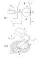
- said regulating means comprise a valve 62 with two flaps 62, 63 movable by a single actuator 61, each flap 62, 63 being disposed in one of the exhaust pipes 21 and recirculation 22 (see Figure 2).
- the displacement of the flap 62 of the valve 60 makes it possible to obstruct said exhaust duct 21, thereby increasing the pressure of the recirculating gases flowing in the low-pressure recirculation duct 22. Furthermore, the displacement of the flap 63 of the valve 60 allows to regulate the rate of flow of recirculating gas circulating in said low-pressure recirculation line 22. The combination of displacement of the two flaps 62, 63 thus makes it possible to optimize the rate of recirculation gas in the admixture regardless of whether the engine speed.
- each of the two flaps 62,63 approximately corresponds to the inner diameter of the pipe in which it is located.
- the flaps 62, 63 are rotatably mounted around the same axis of rotation X.
- the flaps 62, 63 are integral with a single shaft 64 of axis of rotation X connected to the actuator 61, so that here the two flaps 62, 63 are fixed relative to each other.
- the flaps 62,63 of the valve 60 are positioned orthogonally relative to each other along their axis of rotation X.
- the flap 62 of the exhaust pipe 21 is completely open, that is to say positioned parallel to the direction of the gas flow, in the plane XZ in FIG.
- the flap 63 of the low-pressure recirculation duct 22 is completely closed, that is to say in the XY plane in FIG.
- control 61 rotates the mechanically-linked flaps 62, 63 of the desired angle in order to optimize the gas rate. recirculation in the mixture.
- the flap 63 regulates the recirculating gas flow rate flowing in the low-pressure recirculation duct 22, and the flap 62 limits the flow rate of the gas flowing through the exhaust duct 21, thereby simultaneously increasing the pressure and the flow rate of the recirculating gas flow circulating in the low pressure recirculation pipe 22.
- the rotational displacement of the shaft 64 is of the order of 81 °, which avoids completely blocking the exhaust pipe 21.
- the opening of the flap 63 positioned in the recirculation pipe low pressure 22 is only about 90% open.
- FIG. 4 shows an alternative embodiment of the valve 60 of the internal combustion engine 10 according to which the two flaps 61 ', 62' are mounted free relative to each other along the axis of rotation. X '.
- an actuator 61 ' rotates a main shaft 64' of axis of rotation X '. Furthermore, the flap 62 'is mounted in free rotation on the main shaft 64' by means of a pivot connection 68 'and the flap 63' is mounted in free rotation on the main shaft 64 'to the using a pivot link 69 'independent of the pivot link 68'.
- each of the two flaps 62 ', 63 ' corresponds approximately to the inside diameter of the pipe in which it is located.
- the two flaps 61 ', 62' are positioned at the division of the exhaust line into two exhaust lines and low pressure recirculation.
- This strip 63'A is orthogonal to said flap 63 'and serves as relay control for pivoting, thanks to the pivot connection 68', the flap 63 'around the axis of rotation X'.
- a control flap 70 'fixed on the main shaft 64' and, on the other hand, a system of compression springs 65 ', 66 ', 67' set up to bind said flaps 62 ', 63' to the control flap 70 'and to frames 71', 72 ', 73', 74 'so as to rotate the two flaps 62', 63 'around of the axis of rotation X '(see Figure 4).
- a compression spring 65 ' is, on one side, connected to the control flap 70' and, on the other, connected to the flap 63'A of the flap 63 '.
- a compression spring 66 ' is bonded, on one side, to said blade 63'A of the flap 63' and, on the other, linked to a frame 73 '. Said compression spring 66 'has a stiffness almost negligible compared to the stiffness of said compression spring 65'.
- the frame 73 ' serves as a stop flap 63' when the latter has rotated an angle of about 90 °.
- a compression spring 67 ' is, on one side, connected to the flap 62' and, on the other, linked to a frame 74 '.
- Said compression spring 67 ' has the same stiffness as the compression spring 66'.
- the frame 74 ' serves as a stop flap 62' when the latter has rotated an angle of about 81 °.
- the compression spring 67 ' is also slightly compressed and keeps the flap 62' resting against the frame 71 ', so that the surface of the flap 62' is in the plane X'Z 'of FIG. 4, parallel to the direction of the flow of flue gases in the exhaust pipe 21 which is thus open.
- control flap 70 ' is disposed substantially in the plane X'Y' of FIG. 4; the control flap 70 'is therefore substantially superimposed on the flap 63 'and has no contact with the flap 62' which extends orthogonally to said control flap 70 '.
- the actuator 61 ' rotates the main shaft 64' and therefore the control flap 70 '.
- the control flap 70 ' creates a force on the compression spring 65' which retransmits this force, via the blade 63'A, to the compression spring 66 '.
- Said compression spring 66 ' having a stiffness lower than that of the compression spring 65', then compresses. If the rotation angle of the control flap 70 'remains less than 90 °, only the compression spring 66' compresses, causing the flap 63 'to run.
- Said flap 63 'thus pivots at the same angle as the control flap 70' to the end position where the slat 63'A abuts against the frame 73 ', position in which the flap 63' extends parallel to the direction of the recirculation gas flow.
- the section of the low pressure recirculation line 22 is in this case completely open.
- the surface of the flap 62 'not being connected to the control flap 70' the flap 62 'does not change position as the control flap 70' does not rotates no angle greater than 90 °.
- the actuator 61 ' can rotate in the opposite direction the main shaft 64' and thus the control flap 70 'which is associated with him.
- the compression spring 67' makes it possible to push the flap 62 'towards its starting position corresponding to the non-primed recirculation position.
Landscapes
- Engineering & Computer Science (AREA)
- General Engineering & Computer Science (AREA)
- Mechanical Engineering (AREA)
- Chemical & Material Sciences (AREA)
- Combustion & Propulsion (AREA)
- Physics & Mathematics (AREA)
- Thermal Sciences (AREA)
- Exhaust-Gas Circulating Devices (AREA)
- Output Control And Ontrol Of Special Type Engine (AREA)
Abstract
Description
- La présente invention concerne de manière générale les moteurs à combustion interne.
- Elle concerne plus particulièrement un moteur à combustion interne qui comprend d'une part, en aval d'une chambre de combustion, une ligne d'échappement qui se divise en deux conduites dans lesquelles circulent deux flux de gaz brûlés, à savoir une conduite d'échappement débouchant vers l'extérieur et une conduite de recirculation basse pression raccordée à une ligne d'admission d'air située en amont de la chambre de combustion, et d'autre part, des moyens de régulation pour obstruer ladite conduite d'échappement et pour réguler le débit du flux de gaz brûlés circulant dans la conduite de recirculation basse pression.
- L'invention trouve une application particulièrement avantageuse dans la réalisation d'un moteur Diesel dans lequel on fait recirculer une partie des gaz brûlés à basse pression vers la chambre de combustion afin de limiter les émissions de particules polluantes vers l'extérieur.
- Généralement les moteurs à combustion interne du type précité utilisent comme gaz d'admission un mélange d'air frais et de gaz brûlés. Ces gaz brûlés sont appelés communément gaz de recirculation (gaz EGR). Ils sont prélevés par la conduite de recirculation basse pression dans la ligne d'échappement en aval des turbines d'un turbocompresseur et d'un filtre à particules à convertisseur catalytique, et sont introduits dans une conduite d'admission d'air frais en amont du compresseur dudit turbocompresseur.
- Dans les moteurs déjà connus, il est prévu sur cette conduite de recirculation basse pression une soupape commandée électriquement et dont l'ouverture règle le débit de gaz de recirculation dans ladite conduite de recirculation basse pression afin d'obtenir un mélange adéquat d'air frais et de gaz brûlés dans ladite conduite d'admission.
- En outre, dans ces moteurs, il est prévu une vanne à volet sur la conduite d'échappement débouchant vers l'extérieur pour obstruer à la demande
une partie de la section de ladite conduite d'échappement et ainsi augmenter la pression des gaz brûlés dans la conduite de recirculation basse pression. - L'ouverture ou la fermeture de ces vannes permet alors d'obtenir le taux désiré de gaz de recirculation dans le mélange d'admission.
- L'inconvénient principal d'un tel système de vannes est que ces vannes sont pilotées par deux actionneurs différents, de façon disjointe mais successive, pour obtenir le taux souhaité de gaz de recirculation dans le mélange. Le pilotage est ainsi relativement complexe à mettre en oeuvre.
- Afin de remédier à l'inconvénient précité de l'état de la technique, la présente invention propose un moteur à combustion interne dans lequel le débit de gaz de recirculation est commandé de manière simplifiée.
- Plus particulièrement, on propose selon l'invention un moteur à combustion interne tel que défini en introduction, dans lequel il est prévu que les moyens de régulation comprennent une vanne à deux volets déplaçables par un seul actionneur, chaque volet étant disposé dans une des conduites d'échappement et de recirculation basse pression.
- Ainsi, grâce à l'invention, une unique vanne joue le rôle des deux vannes du système de vannes selon l'art antérieur, ce qui permet de réaliser un gain de coût, de poids, d'encombrement et de fiabilité. En outre, le fait d'utiliser un unique actionneur afin de régler le taux de gaz EGR (c'est-à-dire le débit du flux de gaz de recirculation circulant dans ladite conduite de recirculation basse pression) dans le mélange d'admission du moteur selon l'invention a pour effet de simplifier la cartographie de pilotage de l'ensemble.
- Selon une première caractéristique avantageuse du moteur conforme à l'invention, il comprend un filtre à particules à convertisseur catalytique disposé sur la ligne d'échappement en amont desdites conduites d'échappement et de recirculation basse pression.
- Ainsi, les gaz EGR du moteur selon l'invention passent dans le filtre à particules à convertisseur catalytique avant d'être injectés dans le gaz frais, diminuant alors significativement la pollution engendrée par le moteur.
- Selon une autre caractéristique avantageuse du moteur conforme à l'invention, les deux volets sont montés pivotants sur le même axe de rotation.
- Selon un premier mode de réalisation du moteur à combustion interne conforme à l'invention, les deux volets sont montés fixes l'un par rapport à l'autre.
- En outre, selon ce premier mode de réalisation, ces deux volets sont positionnés orthogonalement l'un relativement à l'autre et sont adaptés à pivoter avec un débattement de l'ordre de 81 °.
- Ainsi, avantageusement selon l'invention, lorsque la commande ouvre avec un angle donné le volet positionné dans la conduite de recirculation basse pression, elle ferme simultanément du même angle le volet positionné dans la conduite d'échappement ce qui permet alors d'augmenter la pression des gaz de recirculation circulant dans la conduite de recirculation basse pression.
- Préférentiellement, l'angle de débattement des deux volets est limité à environ 81 ° afin d'éviter de fermer totalement la conduite d'échappement, ce qui étoufferait le moteur.
- Selon un deuxième mode de réalisation du moteur à combustion interne conforme à l'invention, les deux volets sont montés libres l'un par rapport à l'autre.
- Avantageusement, selon ce deuxième mode de réalisation, les deux volets sont positionnés au niveau de la division de la ligne d'échappement en deux conduites d'échappement et de recirculation basse pression.
- En outre, selon ce deuxième mode de réalisation, le volet positionné dans la conduite de recirculation basse pression est adapté à pivoter avec un débattement de 90° et le volet positionné dans la conduite d'échappement est adapté à pivoter avec un débattement de 81 °.
- Par ailleurs, préférentiellement, selon ce deuxième mode de réalisation, l'actionneur est adapté à déplacer de manière successive le volet positionné dans la conduite de recirculation basse pression puis le volet positionné dans la conduite d'échappement.
- Ainsi, selon ce mode de réalisation de l'invention, l'ouverture et la fermeture des volets se fait de manière successive. Cette solution présente l'avantage d'optimiser le rendement du moteur en n'obstruant pas inutilement la conduite d'échappement. Par ailleurs, selon ce mode de réalisation, s'il est possible d'ouvrir ou de fermer totalement la conduite de recirculation basse pression, il n'est pas possible d'obstruer complètement la conduite d'échappement, évitant ainsi tout risque d'étouffement du moteur.
- La description qui va suivre en regard des dessins annexés donnés à titre d'exemples non limitatifs, fera bien comprendre en quoi consiste l'invention et comment elle peut être réalisée.
- Sur les dessins annexés :
- La figure 1 est un schéma de principe simplifié d'un premier mode de réalisation d'un moteur à combustion interne selon l'invention ;
- La figure 2 est une vue schématique de détail de la zone II de la figure 1 ;
- La figure 3 est une vue schématique en perspective de la vanne de la figure 2;
- La figure 4 est une vue schématique en perspective d'une variante de réalisation de la vanne de la figure 3 ;
- Les figures 5A à 5C sont des schémas de principe du fonctionnement de la vanne de la figure 4.
- Sur la figure 1, on a représenté schématiquement un moteur à combustion interne 10 qui comprend une chambre de combustion 11, ici à quatre cylindres 11 A. En sortie de la chambre de combustion 11, le moteur à combustion interne 10 comporte un collecteur 13 de gaz brûlés qui débouche dans une ligne d'échappement 20 qui s'étend jusqu'à un filtre à particules à convertisseur catalytique 40.
- En outre, le moteur à combustion interne 10 comporte sur cette ligne d'échappement 20 un système de turbine 31 d'un turbocompresseur 30.
- A la sortie du filtre à particules à convertisseur catalytique 40, la ligne d'échappement 20 se divise en deux conduites 21,22 dans lesquelles circulent deux flux de gaz brûlés.
- Une des deux conduites 21,22 est une conduite d'échappement 2 1 qui débouche vers l'extérieur 50 via un silencieux 41. L'autre des deux conduites 21,22 est une conduite de recirculation basse pression 22 qui permet d'injecter dans une ligne d'admission d'air 23 une partie des gaz brûlés issus de la combustion, appelés gaz de recirculation, pour réaliser un mélange d'admission comprenant de l'air frais et des gaz brûlés.
- La conduite de recirculation basse pression 22 passe par un refroidisseur secondaire 42 avant de déboucher dans une conduite d'admission 23A d'air frais provenant de l'extérieur via un filtre à air 60.
- Au-delà de la jonction entre la conduite de recirculation basse pression 22 et la conduite d'admission 23A, la ligne d'admission 23 s'étend jusqu'à un répartiteur 12 qui débouche dans la chambre de combustion 11, en passant par le compresseur 32 du turbocompresseur 30 puis par un refroidisseur principal 43.
- Par ailleurs, le moteur à combustion interne 10 comprend des moyens de régulation pour, d'une part, obstruer ladite conduite d'échappement 21, d'autre part, réguler le débit de flux des gaz de recirculation circulant dans la conduite de recirculation basse pression 22 afin d'obtenir le taux désiré de gaz de recirculation dans le mélange d'admission en fonction du régime moteur.
- Selon une caractéristique particulièrement avantageuse du moteur à combustion interne 10, lesdits moyens de régulation comportent une vanne 60 à deux volets 62,63 déplaçables par un seul actionneur 61, chaque volet 62,63 étant disposé dans une des conduites d'échappement 21 et de recirculation 22 (voir figure 2).
- Le déplacement du volet 62 de la vanne 60 permet d'obstruer ladite conduite d'échappement 21, augmentant alors la pression des gaz de recirculation circulant dans la conduite de recirculation basse pression 22. Par ailleurs, le déplacement du volet 63 de la vanne 60 permet de réguler le débit de flux de gaz de recirculation circulant dans ladite conduite de recirculation basse pression 22. La combinaison du déplacement des deux volets 62,63 permet ainsi d'optimiser le taux de gaz de recirculation dans le mélange d'admission quelque soit le régime moteur.
- Comme le montrent plus particulièrement les figures 2 et 3, le diamètre de chacun des deux volets 62,63 correspond approximativement au diamètre intérieur de la conduite dans laquelle il se trouve.
- Préférentiellement, les volets 62,63 sont montés rotatifs autour d'un même axe de rotation X.
- Selon le mode de réalisation représenté sur les figures 2 et 3, les volets 62,63 sont solidaires d'un seul arbre 64 d'axe de rotation X connecté à l'actionneur 61, de sorte qu'ici les deux volets 62,63 sont fixes l'un par rapport à l'autre. En outre, comme le montrent les figures 2 et 3, les volets 62,63 de la vanne 60 sont positionnés orthogonalement l'un par rapport à l'autre selon leur axe de rotation X.
- Ainsi, lorsqu'un volet est en position d'ouverture parallèle à la direction du flux des gaz brûlés dans la conduite considérée, l'autre est en position de fermeture.
- Plus particulièrement, en position de recirculation non amorcée, le volet 62 de la conduite d'échappement 21 est complètement ouvert, c'est-à-dire positionné parallèlement à la direction du flux de gaz, dans le plan XZ sur la figure 3. Le volet 63 de la conduite de recirculation basse pression 22 est quant à lui complètement fermé, c'est-à-dire dans le plan XY sur la figure 3.
- Afin d'amorcer et de régler le débit du flux des gaz de recirculation circulant dans la conduite de recirculation basse pression 22, la commande 61 fait pivoter les volets 62,63 mécaniquement liés de l'angle désiré afin d'optimiser le taux de gaz de recirculation dans le mélange.
- Ainsi, le volet 63 régule le débit de flux de gaz de recirculation circulant dans la conduite de recirculation basse pression 22, et le volet 62 limite le débit du flux de gaz circulant dans la conduite d'échappement 21, augmentant alors simultanément la pression et le débit du flux de gaz de recirculation circulant dans la conduite de recirculation basse pression 22.
- Préférentiellement, le débattement en rotation de l'arbre 64 est de l'ordre de 81 °, ce qui évite d'obstruer totalement la conduite d'échappement 21. De ce fait, l'ouverture du volet 63 positionné dans la conduite de recirculation basse pression 22 n'est ouvert qu'à environ 90%.
- Sur la figure 4, on a représenté une variante de réalisation de la vanne 60 du moteur à combustion interne 10 selon laquelle les deux volets 61',62' sont montés libres l'un par rapport à l'autre selon l'axe de rotation X'.
- Selon ce mode de réalisation, un actionneur 61' commande en rotation un arbre principal 64' d'axe de rotation X'. Par ailleurs, le volet 62' est monté en rotation libre sur l'arbre principal 64' à l'aide d'une liaison pivot 68' et le volet 63' est monté en rotation libre sur l'arbre principal 64' à l'aide d'une liaison pivot 69' indépendante de la liaison pivot 68'.
- Ici également, le volet 62' régule le débit de gaz circulant dans la conduite d'échappement 21 et le volet 63' régule le débit de gaz circulant dans la conduite de recirculation basse pression 22. Le diamètre de chacun des deux volets 62',63' correspond approximativement au diamètre intérieur de la conduite dans laquelle il se trouve.
- En outre, selon ce mode de réalisation représenté sur la figure 4, les deux volets 61',62' sont positionnés au niveau de la division de la ligne d'échappement en deux conduites d'échappement et de recirculation basse pression.
- Par ailleurs, il est prévu une lamelle 63'A fixée au volet 63'. Cette lamelle 63'A est orthogonale audit volet 63' et sert de commande relais pour faire pivoter, grâce à la liaison pivot 68', le volet 63' autour de l'axe de rotation X'.
- En outre, selon ce mode de réalisation, il est prévu, d'une part, un volet de commande 70' fixé sur l'arbre principal 64', et, d'autre part, un système de ressorts de compression 65',66',67' mis en place pour lier lesdits volets 62',63' au volet de commande 70' et à des bâtis 71',72',73',74' afin de faire pivoter les deux volets 62',63' autour de l'axe de rotation X' (voir figure 4).
- Plus particulièrement, un ressort de compression 65' est, d'un côté, lié au volet de commande 70' et, de l'autre, lié à la lamelle 63'A du volet 63'. En outre, un ressort de compression 66' est lié, d'un côté, à ladite lamelle 63'A du volet 63' et, de l'autre, lié à un bâti 73'. Ledit ressort de compression 66' a une raideur presque négligeable par rapport à la raideur dudit ressort de compression 65'.
- Le bâti 73' sert de butée au volet 63' lorsque ce dernier a pivoté d'un angle d'environ 90°.
- Par ailleurs, un ressort de compression 67' est, d'un côté, lié au volet 62' et, de l'autre, lié à un bâti 74'. Ledit ressort de compression 67' possède la même raideur que le ressort de compression 66'. En outre, le bâti 74' sert de butée au volet 62' lorsque ce dernier a pivoté d'un angle d'environ 81 °.
- En position de recirculation non amorcée, le ressort de compression 65' est totalement détendu et le ressort de compression 66' est peu compressé, maintenant ainsi la lamelle 63'A du volet 63' en appui contre le bâti 72', de sorte que la surface du volet 63' se trouve dans le plan X'Y' sur la figure 4, obstruant alors totalement la conduite de recirculation basse pression 22'.
- Le ressort de compression 67' est lui aussi peu compressé et maintient le volet 62' en appui contre le bâti 71', de sorte que la surface du volet 62' se trouve dans le plan X'Z' de la figure 4, parallèlement à la direction du flux des gaz brûlés dans la conduite d'échappement 21 qui est ainsi ouverte.
- Par ailleurs, la surface du volet de commande 70' est disposée sensiblement dans le plan X'Y' de la figure 4 ; le volet de commande 70' est donc pratiquement superposé au volet 63' et n'a aucun contact avec le volet 62' qui s'étend orthogonalement audit volet de commande 70'.
- Pour amorcer le flux de gaz de recirculation dans la conduite de recirculation basse pression 22, l'actionneur 61' fait pivoter l'arbre principal 64' et donc le volet de commande 70'.
- Comme le montrent plus particulièrement les figures 5A et 5B, le volet de commande 70' crée un effort sur le ressort de compression 65' qui retransmet cet effort, via la lamelle 63'A, au ressort de compression 66'. Ledit ressort de compression 66', ayant une raideur plus faible que celle du ressort de compression 65', se comprime alors. Si l'angle de rotation du volet de commande 70' reste inférieur à 90°, seul le ressort de compression 66' se comprime, entraînant dans sa course le volet 63'.
- Ledit volet 63' pivote donc du même angle que le volet de commande 70' jusqu'à la position extrême où la lamelle 63'A vient en butée contre le bâti 73', position dans laquelle le volet 63' s'étend parallèlement à la direction du flux de gaz de recirculation. La section de la conduite de recirculation basse pression 22 est dans ce cas complètement ouverte.
- Par ailleurs, comme le montrent également les figures 5A et 5B, la surface du volet 62' n'étant pas reliée au volet de commande 70', ce volet 62' ne change pas de position tant que le volet de commande 70' ne pivote pas d'un angle supérieur à 90°.
- En revanche, comme le montre plus particulièrement la figure 5C, lorsque le volet de commande 70' pivote d'un angle supérieur à 90°, il entre en contact avec le volet 62' et l'entraîne ainsi dans sa rotation. Le ressort de compression 67' se comprime alors, laissant ledit volet 62' pivoter.
- Par ailleurs, comme le montre également la figure 5C, toujours lorsque le volet de commande 70' pivote d'un angle supérieur à 90°, la lamelle 63'A du volet 63' reste en butée contre le bâti 73'. Le volet de commande 70' comprime alors le ressort de compression 65' contre cette lamelle 63'A.
- Enfin, lorsque le volet de commande 70' a effectué une rotation de l'ordre de 171 ° (90°+81 °), le volet 62' arrive en butée contre le bâti 74', bloquant ainsi la rotation dudit volet de commande 70'. La conduite d'échappement 21 n'est donc jamais complètement obstruée. Dans cette position de recirculation complètement amorcée, la conduite d'échappement 21 est à 90% obstruée et la conduite de recirculation basse pression 22 totalement ouverte.
- A n'importe quel angle de commande entre la position de recirculation non amorcée et la position de recirculation complètement amorcée, l'actionneur 61' peut faire pivoter dans le sens inverse l'arbre principal 64' et donc le volet de commande 70' qui lui est associé.
- Lorsque le volet de commande 70' pivote dans le sens inverse, le ressort de compression 65' se détend. Lorsque ledit ressort de compression 65' est totalement détendu, le ressort de compression 66' pousse la lamelle 63'A du volet 63' vers sa position de départ correspondant à la position de recirculation non amorcée.
- Par ailleurs, toujours lorsque le volet de commande 70' pivote dans le sens inverse, le ressort de compression 67' permet de pousser le volet 62' vers sa position de départ correspondant à la position de recirculation non amorcée.
- La présente invention n'est nullement limitée aux modes de réalisation décrits et représentés, mais l'homme de métier saura y apporter toute variante conforme à son esprit.
Claims (10)
- Moteur à combustion interne (10) qui comprend d'une part, en aval d'une chambre de combustion (11), une ligne d'échappement (20) qui se divise en deux conduites (21,22) dans lesquelles circulent deux flux de gaz brûlés, à savoir une conduite d'échappement (21) débouchant vers l'extérieur et une conduite de recirculation basse pression (22) raccordée à une ligne d'admission d'air (23) située en amont de la chambre de combustion (11), et d'autre part, des moyens de régulation (60) pour obstruer ladite conduite d'échappement (21) et pour réguler le débit du flux de gaz brûlés circulant dans la conduite de recirculation basse pression (22), caractérisé en ce que lesdits moyens de régulation comprennent une vanne (60) à deux volets (62,63;62',63') déplaçables par un seul actionneur (61;61'), chaque volet (62,63;62',63') étant disposé dans des conduites d'échappement (21) et de recirculation basse pression (22).
- Moteur à combustion interne (10) selon la revendication 1, caractérisé en ce qu'il comprend un filtre à particules à convertisseur catalytique (40) disposé sur la ligne d'échappement (20), en amont desdites conduites d'échappement (21) et de recirculation basse pression (22).
- Moteur à combustion interne (10) selon la revendication 1 ou 2, caractérisé en ce que les deux volets (62,63 ;62',63') sont montés rotatifs autour d'un même axe de rotation (X).
- Moteur à combustion interne (10) selon l'une des revendications 1 à 3, caractérisé en ce que les deux volets (62,63) sont montés fixes l'un par rapport à l'autre.
- Moteur à combustion interne (10) selon l'une des revendications 1 à 4, caractérisé en ce que les deux volets (62,63) sont positionnés orthogonalement l'un par rapport à l'autre selon leur axe de rotation (X).
- Moteur à combustion interne (10) selon les revendications 4 et 5, caractérisé en ce que les deux volets (62,63) sont adaptés à pivoter avec un débattement de l'ordre de 81 °.
- Moteur à combustion interne (10) selon l'une des revendications 1 à 3, caractérisé en ce que les deux volets (62',63') sont montés libres l'un par rapport à l'autre.
- Moteur à combustion interne (10) selon la revendication 7, caractérisé en ce que lesdits volets (62',63') sont positionnés au niveau de la division de la ligne d'échappement (20) en deux conduites d'échappement (21) et de recirculation basse pression (22).
- Moteur à combustion interne (10) selon la revendication 7 ou 8, caractérisé en ce que le volet (63') positionné dans la conduite de recirculation basse pression (22) est adapté à pivoter avec un débattement de l'ordre de 90° et le volet (62') positionné dans la conduite d'échappement (21) est adapté à pivoter avec un débattement de l'ordre de 81 °.
- Moteur à combustion interne (10) selon la revendication 9, caractérisé en ce que l'actionneur (61') est adapté à déplacer successivement le volet (63') positionné dans la conduite de recirculation basse pression (22) puis le volet (62') positionné dans la conduite d'échappement (21).
Applications Claiming Priority (1)
| Application Number | Priority Date | Filing Date | Title |
|---|---|---|---|
| FR0502474A FR2883039B1 (fr) | 2005-03-14 | 2005-03-14 | Moteur a combustion interne avec un systeme de vanne pour reguler le taux de gaz de recirculation dans le melange d'admission, et le vehicule automobile comprenant un tel moteur |
Publications (2)
| Publication Number | Publication Date |
|---|---|
| EP1707781A1 true EP1707781A1 (fr) | 2006-10-04 |
| EP1707781B1 EP1707781B1 (fr) | 2008-04-02 |
Family
ID=34978648
Family Applications (1)
| Application Number | Title | Priority Date | Filing Date |
|---|---|---|---|
| EP06300138A Expired - Lifetime EP1707781B1 (fr) | 2005-03-14 | 2006-02-15 | Moteur à combustion interne avec un système de vanne pour réguler le taux de gaz de recirculation dans le mélange d'admission, et le véhicule automobile comprenant un tel moteur. |
Country Status (4)
| Country | Link |
|---|---|
| EP (1) | EP1707781B1 (fr) |
| AT (1) | ATE391230T1 (fr) |
| DE (1) | DE602006000839T2 (fr) |
| FR (1) | FR2883039B1 (fr) |
Cited By (2)
| Publication number | Priority date | Publication date | Assignee | Title |
|---|---|---|---|---|
| EP2211048A1 (fr) * | 2009-01-23 | 2010-07-28 | Pierburg GmbH | Dispositif de clapets de gaz d'échappement et système de récupération thermique à l'échappement d'un moteur à combustion interne |
| FR3048023A1 (fr) * | 2016-02-24 | 2017-08-25 | Peugeot Citroen Automobiles Sa | Ensemble moteur comprenant un dispositif de recirculation de gaz d’echappement a filtre cyclonique |
Families Citing this family (3)
| Publication number | Priority date | Publication date | Assignee | Title |
|---|---|---|---|---|
| DE102010052563A1 (de) * | 2010-11-25 | 2012-05-31 | Volkswagen Ag | Einrichtung zur Beeinflussung von Gas-Volumenströmen, Verfahren zur Steuerung und/oder Regelung eines Abgasstromes oder eines Ladeluftstromes, Abgasstrang und Kraftfahrzeug |
| FR3048027B1 (fr) * | 2016-02-18 | 2020-01-17 | Renault S.A.S. | "moteur a combustion interne comportant des moyens de regulation de la temperature de l'air de suralimentation" |
| DE102016218808A1 (de) | 2016-09-29 | 2018-03-29 | Ford Global Technologies, Llc | Selbstzündende Brennkraftmaschine mit Abgasrückführung und Verfahren zum Betreiben einer derartigen Brennkraftmaschine |
Citations (7)
| Publication number | Priority date | Publication date | Assignee | Title |
|---|---|---|---|---|
| US1398976A (en) * | 1921-12-06 | Cut-out valve | ||
| US4566424A (en) * | 1984-07-30 | 1986-01-28 | Outboard Marine Corporation | Flexible coupling for carburetors |
| DE4007516A1 (de) * | 1990-03-09 | 1991-09-12 | Kloeckner Humboldt Deutz Ag | Dieselmotor |
| EP0702175A1 (fr) * | 1994-09-16 | 1996-03-20 | Fuji Oozx Inc. | Vanne de réglage pour fluide |
| US5740785A (en) * | 1997-06-09 | 1998-04-21 | Southwest Research Institute | Two way-high pressure loop, exhaust gas recirculation valve |
| EP1365124A1 (fr) * | 2002-05-22 | 2003-11-26 | Peugeot Citroen Automobiles SA | Système d'alimentation en gaz d'un moteur diesel de véhicule automobile |
| EP1505281A2 (fr) * | 2003-08-02 | 2005-02-09 | Mann + Hummel GmbH | Module d'admission |
-
2005
- 2005-03-14 FR FR0502474A patent/FR2883039B1/fr not_active Expired - Lifetime
-
2006
- 2006-02-15 DE DE602006000839T patent/DE602006000839T2/de not_active Expired - Lifetime
- 2006-02-15 AT AT06300138T patent/ATE391230T1/de not_active IP Right Cessation
- 2006-02-15 EP EP06300138A patent/EP1707781B1/fr not_active Expired - Lifetime
Patent Citations (7)
| Publication number | Priority date | Publication date | Assignee | Title |
|---|---|---|---|---|
| US1398976A (en) * | 1921-12-06 | Cut-out valve | ||
| US4566424A (en) * | 1984-07-30 | 1986-01-28 | Outboard Marine Corporation | Flexible coupling for carburetors |
| DE4007516A1 (de) * | 1990-03-09 | 1991-09-12 | Kloeckner Humboldt Deutz Ag | Dieselmotor |
| EP0702175A1 (fr) * | 1994-09-16 | 1996-03-20 | Fuji Oozx Inc. | Vanne de réglage pour fluide |
| US5740785A (en) * | 1997-06-09 | 1998-04-21 | Southwest Research Institute | Two way-high pressure loop, exhaust gas recirculation valve |
| EP1365124A1 (fr) * | 2002-05-22 | 2003-11-26 | Peugeot Citroen Automobiles SA | Système d'alimentation en gaz d'un moteur diesel de véhicule automobile |
| EP1505281A2 (fr) * | 2003-08-02 | 2005-02-09 | Mann + Hummel GmbH | Module d'admission |
Cited By (2)
| Publication number | Priority date | Publication date | Assignee | Title |
|---|---|---|---|---|
| EP2211048A1 (fr) * | 2009-01-23 | 2010-07-28 | Pierburg GmbH | Dispositif de clapets de gaz d'échappement et système de récupération thermique à l'échappement d'un moteur à combustion interne |
| FR3048023A1 (fr) * | 2016-02-24 | 2017-08-25 | Peugeot Citroen Automobiles Sa | Ensemble moteur comprenant un dispositif de recirculation de gaz d’echappement a filtre cyclonique |
Also Published As
| Publication number | Publication date |
|---|---|
| FR2883039A1 (fr) | 2006-09-15 |
| FR2883039B1 (fr) | 2007-04-20 |
| EP1707781B1 (fr) | 2008-04-02 |
| DE602006000839D1 (de) | 2008-05-15 |
| ATE391230T1 (de) | 2008-04-15 |
| DE602006000839T2 (de) | 2009-04-09 |
Similar Documents
| Publication | Publication Date | Title |
|---|---|---|
| EP0701057A1 (fr) | Tubulure d'admission d'air à volets pivotants pour moteur à combustion interne | |
| EP2954183B1 (fr) | Dispositif d'orientation des gaz d'échappement | |
| EP2010770A1 (fr) | Dispositif d'admission d'air d'un moteur thermique ayant un circuit principal refroidi et un circuit derive pourvu de moyens de chauffage | |
| EP2783097B1 (fr) | Vanne de controle pour systeme de recirculation des gaz d'echappement d'un moteur a combustion interne | |
| EP1707781B1 (fr) | Moteur à combustion interne avec un système de vanne pour réguler le taux de gaz de recirculation dans le mélange d'admission, et le véhicule automobile comprenant un tel moteur. | |
| WO2016128642A1 (fr) | Ensemble moteur turbocompresse a deux conduits d'echappement avec ligne de recirculation | |
| FR2927975A1 (fr) | Vanne pour une ligne d'echappement de vehicule automobile et ligne d'echappement comprenant une telle vanne. | |
| FR2920853A1 (fr) | Vanne pour circuit d'alimentation en air d'un moteur de vehicule automobile, circuit comportant une telle vanne et procede de commande d'un moteur utilisant un tel circuit | |
| FR3007071A1 (fr) | Moteur thermique a actionneur commun pour vanne egr et vanne d'air | |
| EP2769074B1 (fr) | Vanne de circulation de gaz d'échappement d'un moteur, notamment moteur de véhicule automobile | |
| FR2910536A1 (fr) | Moteur a combustion interne suralimente comprenant des collecteurs d'echappement a volume variable. | |
| FR2983521A3 (fr) | Pot catalytique et moteur equipe d'un tel pot | |
| FR2768774A1 (fr) | Appareil d'admission de moteur a combustion interne | |
| WO2022117934A1 (fr) | Ecope pour une turbomachine d'aeronef | |
| FR2845732A1 (fr) | Systeme de commande du fonctionnement d'un moteur a combustion interne et procede de commande de la recirculation des gaz d'echappement au moyen d'un tel systeme de commande. | |
| FR2924165A3 (fr) | Culasse de moteur a combustion interne dont les conduits d'admission presentent un meplat generateur de tourbillons axiaux | |
| EP2767695B1 (fr) | Vanne de conduite de dérivation d'un turbocompresseur munie d'un volet de fermeture à déflecteur | |
| WO2007093729A2 (fr) | Circuit d'air d'admission pour moteur a combustion interne | |
| EP3217007B1 (fr) | Vanne de modulation simultanée de deux flux fluide, notamment pour dosage de gaz recirculés dans un moteur à combustion interne | |
| WO2013171413A1 (fr) | Doseur deux voies et applications dudit doseur | |
| FR3071885A1 (fr) | Collecteur d'admission a encombrement reduit | |
| FR3055027A3 (fr) | By-pass double clapet | |
| FR2930286A3 (fr) | Raccord d'une ligne d'echappement avec une ligne de recirculation et moteur a combustion interne comportant un tel raccord | |
| FR3130882A1 (fr) | Groupe moteur à combustion interne comportant un circuit d’échappement avec un capteur de concentration d’oxydes d’azote | |
| FR2847946A1 (fr) | Systeme de recirculation de gaz d'echappement perfectionne pour moteur a combustion interne de vehicule automobile |
Legal Events
| Date | Code | Title | Description |
|---|---|---|---|
| PUAI | Public reference made under article 153(3) epc to a published international application that has entered the european phase |
Free format text: ORIGINAL CODE: 0009012 |
|
| AK | Designated contracting states |
Kind code of ref document: A1 Designated state(s): AT BE BG CH CY CZ DE DK EE ES FI FR GB GR HU IE IS IT LI LT LU LV MC NL PL PT RO SE SI SK TR |
|
| AX | Request for extension of the european patent |
Extension state: AL BA HR MK YU |
|
| 17P | Request for examination filed |
Effective date: 20061027 |
|
| AKX | Designation fees paid |
Designated state(s): AT BE BG CH CY CZ DE DK EE ES FI FR GB GR HU IE IS IT LI LT LU LV MC NL PL PT RO SE SI SK TR |
|
| GRAP | Despatch of communication of intention to grant a patent |
Free format text: ORIGINAL CODE: EPIDOSNIGR1 |
|
| GRAS | Grant fee paid |
Free format text: ORIGINAL CODE: EPIDOSNIGR3 |
|
| GRAA | (expected) grant |
Free format text: ORIGINAL CODE: 0009210 |
|
| AK | Designated contracting states |
Kind code of ref document: B1 Designated state(s): AT BE BG CH CY CZ DE DK EE ES FI FR GB GR HU IE IS IT LI LT LU LV MC NL PL PT RO SE SI SK TR |
|
| RAP1 | Party data changed (applicant data changed or rights of an application transferred) |
Owner name: RENAULT S.A.S. |
|
| REG | Reference to a national code |
Ref country code: GB Ref legal event code: FG4D Free format text: NOT ENGLISH |
|
| REG | Reference to a national code |
Ref country code: CH Ref legal event code: EP Ref country code: IE Ref legal event code: FG4D Free format text: LANGUAGE OF EP DOCUMENT: FRENCH |
|
| REF | Corresponds to: |
Ref document number: 602006000839 Country of ref document: DE Date of ref document: 20080515 Kind code of ref document: P |
|
| PG25 | Lapsed in a contracting state [announced via postgrant information from national office to epo] |
Ref country code: SI Free format text: LAPSE BECAUSE OF FAILURE TO SUBMIT A TRANSLATION OF THE DESCRIPTION OR TO PAY THE FEE WITHIN THE PRESCRIBED TIME-LIMIT Effective date: 20080402 |
|
| NLV1 | Nl: lapsed or annulled due to failure to fulfill the requirements of art. 29p and 29m of the patents act | ||
| REG | Reference to a national code |
Ref country code: IE Ref legal event code: FD4D |
|
| PG25 | Lapsed in a contracting state [announced via postgrant information from national office to epo] |
Ref country code: BG Free format text: LAPSE BECAUSE OF FAILURE TO SUBMIT A TRANSLATION OF THE DESCRIPTION OR TO PAY THE FEE WITHIN THE PRESCRIBED TIME-LIMIT Effective date: 20080702 Ref country code: ES Free format text: LAPSE BECAUSE OF FAILURE TO SUBMIT A TRANSLATION OF THE DESCRIPTION OR TO PAY THE FEE WITHIN THE PRESCRIBED TIME-LIMIT Effective date: 20080713 Ref country code: PT Free format text: LAPSE BECAUSE OF FAILURE TO SUBMIT A TRANSLATION OF THE DESCRIPTION OR TO PAY THE FEE WITHIN THE PRESCRIBED TIME-LIMIT Effective date: 20080903 Ref country code: NL Free format text: LAPSE BECAUSE OF FAILURE TO SUBMIT A TRANSLATION OF THE DESCRIPTION OR TO PAY THE FEE WITHIN THE PRESCRIBED TIME-LIMIT Effective date: 20080402 Ref country code: FI Free format text: LAPSE BECAUSE OF FAILURE TO SUBMIT A TRANSLATION OF THE DESCRIPTION OR TO PAY THE FEE WITHIN THE PRESCRIBED TIME-LIMIT Effective date: 20080402 |
|
| PG25 | Lapsed in a contracting state [announced via postgrant information from national office to epo] |
Ref country code: LV Free format text: LAPSE BECAUSE OF FAILURE TO SUBMIT A TRANSLATION OF THE DESCRIPTION OR TO PAY THE FEE WITHIN THE PRESCRIBED TIME-LIMIT Effective date: 20080402 Ref country code: PL Free format text: LAPSE BECAUSE OF FAILURE TO SUBMIT A TRANSLATION OF THE DESCRIPTION OR TO PAY THE FEE WITHIN THE PRESCRIBED TIME-LIMIT Effective date: 20080402 Ref country code: AT Free format text: LAPSE BECAUSE OF FAILURE TO SUBMIT A TRANSLATION OF THE DESCRIPTION OR TO PAY THE FEE WITHIN THE PRESCRIBED TIME-LIMIT Effective date: 20080402 |
|
| PG25 | Lapsed in a contracting state [announced via postgrant information from national office to epo] |
Ref country code: IS Free format text: LAPSE BECAUSE OF FAILURE TO SUBMIT A TRANSLATION OF THE DESCRIPTION OR TO PAY THE FEE WITHIN THE PRESCRIBED TIME-LIMIT Effective date: 20080802 |
|
| PG25 | Lapsed in a contracting state [announced via postgrant information from national office to epo] |
Ref country code: CZ Free format text: LAPSE BECAUSE OF FAILURE TO SUBMIT A TRANSLATION OF THE DESCRIPTION OR TO PAY THE FEE WITHIN THE PRESCRIBED TIME-LIMIT Effective date: 20080402 Ref country code: SE Free format text: LAPSE BECAUSE OF FAILURE TO SUBMIT A TRANSLATION OF THE DESCRIPTION OR TO PAY THE FEE WITHIN THE PRESCRIBED TIME-LIMIT Effective date: 20080702 Ref country code: DK Free format text: LAPSE BECAUSE OF FAILURE TO SUBMIT A TRANSLATION OF THE DESCRIPTION OR TO PAY THE FEE WITHIN THE PRESCRIBED TIME-LIMIT Effective date: 20080402 Ref country code: LT Free format text: LAPSE BECAUSE OF FAILURE TO SUBMIT A TRANSLATION OF THE DESCRIPTION OR TO PAY THE FEE WITHIN THE PRESCRIBED TIME-LIMIT Effective date: 20080402 Ref country code: IE Free format text: LAPSE BECAUSE OF FAILURE TO SUBMIT A TRANSLATION OF THE DESCRIPTION OR TO PAY THE FEE WITHIN THE PRESCRIBED TIME-LIMIT Effective date: 20080402 |
|
| PLBE | No opposition filed within time limit |
Free format text: ORIGINAL CODE: 0009261 |
|
| STAA | Information on the status of an ep patent application or granted ep patent |
Free format text: STATUS: NO OPPOSITION FILED WITHIN TIME LIMIT |
|
| PG25 | Lapsed in a contracting state [announced via postgrant information from national office to epo] |
Ref country code: RO Free format text: LAPSE BECAUSE OF FAILURE TO SUBMIT A TRANSLATION OF THE DESCRIPTION OR TO PAY THE FEE WITHIN THE PRESCRIBED TIME-LIMIT Effective date: 20080402 Ref country code: SK Free format text: LAPSE BECAUSE OF FAILURE TO SUBMIT A TRANSLATION OF THE DESCRIPTION OR TO PAY THE FEE WITHIN THE PRESCRIBED TIME-LIMIT Effective date: 20080402 |
|
| 26N | No opposition filed |
Effective date: 20090106 |
|
| PG25 | Lapsed in a contracting state [announced via postgrant information from national office to epo] |
Ref country code: EE Free format text: LAPSE BECAUSE OF FAILURE TO SUBMIT A TRANSLATION OF THE DESCRIPTION OR TO PAY THE FEE WITHIN THE PRESCRIBED TIME-LIMIT Effective date: 20080402 |
|
| BERE | Be: lapsed |
Owner name: RENAULT S.A.S. Effective date: 20090228 |
|
| PG25 | Lapsed in a contracting state [announced via postgrant information from national office to epo] |
Ref country code: IT Free format text: LAPSE BECAUSE OF FAILURE TO SUBMIT A TRANSLATION OF THE DESCRIPTION OR TO PAY THE FEE WITHIN THE PRESCRIBED TIME-LIMIT Effective date: 20080402 |
|
| PG25 | Lapsed in a contracting state [announced via postgrant information from national office to epo] |
Ref country code: CY Free format text: LAPSE BECAUSE OF FAILURE TO SUBMIT A TRANSLATION OF THE DESCRIPTION OR TO PAY THE FEE WITHIN THE PRESCRIBED TIME-LIMIT Effective date: 20080402 Ref country code: MC Free format text: LAPSE BECAUSE OF NON-PAYMENT OF DUE FEES Effective date: 20090228 |
|
| REG | Reference to a national code |
Ref country code: FR Ref legal event code: ST Effective date: 20091030 |
|
| PG25 | Lapsed in a contracting state [announced via postgrant information from national office to epo] |
Ref country code: BE Free format text: LAPSE BECAUSE OF NON-PAYMENT OF DUE FEES Effective date: 20090228 |
|
| PG25 | Lapsed in a contracting state [announced via postgrant information from national office to epo] |
Ref country code: FR Free format text: LAPSE BECAUSE OF NON-PAYMENT OF DUE FEES Effective date: 20090302 |
|
| REG | Reference to a national code |
Ref country code: CH Ref legal event code: PL |
|
| PG25 | Lapsed in a contracting state [announced via postgrant information from national office to epo] |
Ref country code: CH Free format text: LAPSE BECAUSE OF NON-PAYMENT OF DUE FEES Effective date: 20100228 Ref country code: GR Free format text: LAPSE BECAUSE OF FAILURE TO SUBMIT A TRANSLATION OF THE DESCRIPTION OR TO PAY THE FEE WITHIN THE PRESCRIBED TIME-LIMIT Effective date: 20080703 Ref country code: LI Free format text: LAPSE BECAUSE OF NON-PAYMENT OF DUE FEES Effective date: 20100228 |
|
| PG25 | Lapsed in a contracting state [announced via postgrant information from national office to epo] |
Ref country code: LU Free format text: LAPSE BECAUSE OF NON-PAYMENT OF DUE FEES Effective date: 20090215 |
|
| PG25 | Lapsed in a contracting state [announced via postgrant information from national office to epo] |
Ref country code: HU Free format text: LAPSE BECAUSE OF FAILURE TO SUBMIT A TRANSLATION OF THE DESCRIPTION OR TO PAY THE FEE WITHIN THE PRESCRIBED TIME-LIMIT Effective date: 20081003 |
|
| PG25 | Lapsed in a contracting state [announced via postgrant information from national office to epo] |
Ref country code: TR Free format text: LAPSE BECAUSE OF FAILURE TO SUBMIT A TRANSLATION OF THE DESCRIPTION OR TO PAY THE FEE WITHIN THE PRESCRIBED TIME-LIMIT Effective date: 20080402 |
|
| PGFP | Annual fee paid to national office [announced via postgrant information from national office to epo] |
Ref country code: DE Payment date: 20180219 Year of fee payment: 13 Ref country code: GB Payment date: 20180216 Year of fee payment: 13 |
|
| REG | Reference to a national code |
Ref country code: DE Ref legal event code: R119 Ref document number: 602006000839 Country of ref document: DE |
|
| GBPC | Gb: european patent ceased through non-payment of renewal fee |
Effective date: 20190215 |
|
| PG25 | Lapsed in a contracting state [announced via postgrant information from national office to epo] |
Ref country code: GB Free format text: LAPSE BECAUSE OF NON-PAYMENT OF DUE FEES Effective date: 20190215 Ref country code: DE Free format text: LAPSE BECAUSE OF NON-PAYMENT OF DUE FEES Effective date: 20190903 |