EP1707464B1 - Hydraulic brake system with anti-lock control - Google Patents
Hydraulic brake system with anti-lock control Download PDFInfo
- Publication number
- EP1707464B1 EP1707464B1 EP06111375A EP06111375A EP1707464B1 EP 1707464 B1 EP1707464 B1 EP 1707464B1 EP 06111375 A EP06111375 A EP 06111375A EP 06111375 A EP06111375 A EP 06111375A EP 1707464 B1 EP1707464 B1 EP 1707464B1
- Authority
- EP
- European Patent Office
- Prior art keywords
- pressure
- low
- filling
- nds
- degree
- Prior art date
- Legal status (The legal status is an assumption and is not a legal conclusion. Google has not performed a legal analysis and makes no representation as to the accuracy of the status listed.)
- Active
Links
- 238000000034 method Methods 0.000 claims description 3
- 230000001105 regulatory effect Effects 0.000 claims description 3
- 230000004913 activation Effects 0.000 claims 1
- 238000001994 activation Methods 0.000 claims 1
- 238000010586 diagram Methods 0.000 claims 1
- 230000003044 adaptive effect Effects 0.000 description 2
- 238000006243 chemical reaction Methods 0.000 description 1
- 238000004891 communication Methods 0.000 description 1
- 238000010276 construction Methods 0.000 description 1
- 238000006073 displacement reaction Methods 0.000 description 1
- 230000000694 effects Effects 0.000 description 1
- 239000012530 fluid Substances 0.000 description 1
- 238000012423 maintenance Methods 0.000 description 1
- 239000011159 matrix material Substances 0.000 description 1
- 230000003134 recirculating effect Effects 0.000 description 1
Images

Classifications
-
- B—PERFORMING OPERATIONS; TRANSPORTING
- B60—VEHICLES IN GENERAL
- B60T—VEHICLE BRAKE CONTROL SYSTEMS OR PARTS THEREOF; BRAKE CONTROL SYSTEMS OR PARTS THEREOF, IN GENERAL; ARRANGEMENT OF BRAKING ELEMENTS ON VEHICLES IN GENERAL; PORTABLE DEVICES FOR PREVENTING UNWANTED MOVEMENT OF VEHICLES; VEHICLE MODIFICATIONS TO FACILITATE COOLING OF BRAKES
- B60T8/00—Arrangements for adjusting wheel-braking force to meet varying vehicular or ground-surface conditions, e.g. limiting or varying distribution of braking force
- B60T8/32—Arrangements for adjusting wheel-braking force to meet varying vehicular or ground-surface conditions, e.g. limiting or varying distribution of braking force responsive to a speed condition, e.g. acceleration or deceleration
- B60T8/34—Arrangements for adjusting wheel-braking force to meet varying vehicular or ground-surface conditions, e.g. limiting or varying distribution of braking force responsive to a speed condition, e.g. acceleration or deceleration having a fluid pressure regulator responsive to a speed condition
- B60T8/42—Arrangements for adjusting wheel-braking force to meet varying vehicular or ground-surface conditions, e.g. limiting or varying distribution of braking force responsive to a speed condition, e.g. acceleration or deceleration having a fluid pressure regulator responsive to a speed condition having expanding chambers for controlling pressure, i.e. closed systems
- B60T8/4275—Pump-back systems
-
- B—PERFORMING OPERATIONS; TRANSPORTING
- B60—VEHICLES IN GENERAL
- B60T—VEHICLE BRAKE CONTROL SYSTEMS OR PARTS THEREOF; BRAKE CONTROL SYSTEMS OR PARTS THEREOF, IN GENERAL; ARRANGEMENT OF BRAKING ELEMENTS ON VEHICLES IN GENERAL; PORTABLE DEVICES FOR PREVENTING UNWANTED MOVEMENT OF VEHICLES; VEHICLE MODIFICATIONS TO FACILITATE COOLING OF BRAKES
- B60T8/00—Arrangements for adjusting wheel-braking force to meet varying vehicular or ground-surface conditions, e.g. limiting or varying distribution of braking force
- B60T8/32—Arrangements for adjusting wheel-braking force to meet varying vehicular or ground-surface conditions, e.g. limiting or varying distribution of braking force responsive to a speed condition, e.g. acceleration or deceleration
- B60T8/34—Arrangements for adjusting wheel-braking force to meet varying vehicular or ground-surface conditions, e.g. limiting or varying distribution of braking force responsive to a speed condition, e.g. acceleration or deceleration having a fluid pressure regulator responsive to a speed condition
- B60T8/40—Arrangements for adjusting wheel-braking force to meet varying vehicular or ground-surface conditions, e.g. limiting or varying distribution of braking force responsive to a speed condition, e.g. acceleration or deceleration having a fluid pressure regulator responsive to a speed condition comprising an additional fluid circuit including fluid pressurising means for modifying the pressure of the braking fluid, e.g. including wheel driven pumps for detecting a speed condition, or pumps which are controlled by means independent of the braking system
- B60T8/404—Control of the pump unit
- B60T8/4059—Control of the pump unit involving the rate of delivery
Definitions
- An electronically controlled, hydraulic brake system comprises a receiving body for both electromagnetically controllable valves, as well as for an electric motor driven pump, which is provided in slip control operation as a return pump to brake fluid is discharged from wheel brakes in one or more low-pressure accumulator, towards the master cylinder (THZ) to promote back.
- an electronic control unit (ECU) is provided, which is connected to the power supply with an electrical system, and for communication with an electronic bus system.
- the electronic control unit with valve coils, with Radcarden and with a variable speed electric motor for driving the pump is electrically connected.
- the valves are controlled in such a time-limited manner in dependence on the prevailing wheel slip that pressure reduction, pressure maintenance and pressure build-up conditions in the wheel brakes can be caused. This is called short as pressure modulation.
- the respective outlet valve of a wheel brake is opened, for example, so that the discharged pressure medium volume can temporarily reach a low-pressure accumulator. So that the brake pedal remains in the activated position, and does not fall abruptly through the drained volume in the direction of the bottom plate, the return pump is used to force the pressure medium volume, which has been discharged from the wheel brakes in the low-pressure accumulator, back towards the master cylinder. This The driver often recognizes this process by pedal vibrations and by the running noise of the electric motor, as well as by running noises of the pump. Furthermore, pressure surges due to abrupt valve opening and valve closing operations usually belong to said repertoire.
- the DE 196 32 311 A1 maps the level of the low-pressure accumulator through a theoretically calculated volume model and specifies the speed of a hydraulic pump, which is required to empty the low pressure accumulator in the period between two consecutive Bremstikabbauphasen with high security.
- the invention is based on the basic idea to make the setting or adjustment of the target engine speed based on a map in which the parameters driver pre-pressure and degree of filling of the low-pressure accumulator come together as input variables.
- the map is mathematically-parametrized in the form of a matrix in the electronic controller can be stored. This allows an adaptive pump control by adaptive - ie depending on the prevailing boundary conditions and requirements, a fast or a slow emptying of the low-pressure accumulator is possible. It is intended to take the electric motor with high or low speed in operation. In other words, it is possible to refrain from a particularly rapid emptying of a low-pressure accumulator at predetermined situations.
- the modified pump strategy is selected when indicated by the low pressure accumulator volume to be evacuated empty.
- the invention makes it possible to avoid a temporary over-rotation of the pump and uncomfortable pedal reactions as a result of discontinuous return conveyance.
- the conveying effect is continuously performed depending on the above-mentioned influencing variables, and thus the comfort in pump operation is improved.
- the degree of filling of the low-pressure accumulator can be measured directly or determined by other boundary conditions - in other words estimated.
- the pattern of the solenoid valve actuations for example, in terms of valve actuation times, in particular Ventilbestromungs committee and / or PWM modulation patterns recommended, as far as analogized controllable switching valves are used.
- the map with the above-mentioned boundary conditions driver pre-pressure (P_thx) and degree of filling (NDS_V_thy) can be formulated as follows.
- Fig. 1 is a map according to Table 1 graphically illustrated.
- the correspondingly requested engine speed is illustrated as an obliquely arranged in the coordinate space surface.
- the engine speed to be controlled is divided into 5 different speed ranges according to the results of the input variables.
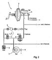
- Fig. 2 describes the construction and the interconnection of the hydraulic brake system in the simplified example of only one brake circuit with only one wheel brake.
- an actuating unit 1 is provided with a brake booster 2 and with a master cylinder 3, THZ, which is connected with its pressure chamber via a normally open inlet valve 4 (SO) hydraulically connected to a wheel brake 5.
- the electronic controller is not clear.
- a pressure sensor may be provided for detecting the pressure PTHZ in the pressure chamber (admission pressure) of the master cylinder 3.
- the actuating unit 1 makes it possible to build up pressure in the wheel brake 5 for the purpose of braking.
- the wheel rotational behavior is detected by a symbolically clarified wheel sensor 6.
- the wheel brake 5 On an outlet side, the wheel brake 5 has a normally closed exhaust valve 7 (SG), which is connected to a low pressure accumulator 8 (NDS).
- the low-pressure accumulator 8 is followed by a suction side of an electric motor-driven hydraulic pump 9, whose pressure side is connected to a hydraulic channel which connects the master cylinder 3 to the wheel brake 5.
- the arrangement allows a pressure modulation, for example by closing the inlet valve 4, and opening the outlet valve 7, and releasing hydraulic pressure from the wheel brake 5, in that pressure medium can flow into the low-pressure reservoir 8.
- the discharged pressure medium is conveyed by the hydraulic pump 9 again in the direction of the master cylinder 3, in front of the wheel brake 5.
- a decrease in the brake pedal and a depletion of the pressure medium is prevented (closed system).
- the setpoint speed of the electric motor is set or regulated as a function of the degree of filling in the at least one low-pressure accumulator 8.
- the degree of filling in the low-pressure accumulator 8 is measured directly - for example with the aid of a sensor, in particular a displacement sensor on the low-pressure accumulator 8.
- Output signals of the sensor are fed to the electronic controller, for example by wire or wireless.
- the degree of filling of the low-pressure accumulator 8 is determined - in other words estimated. This is done with the help of the electronic controller on the basis of the valve actuation pattern which it emits for the purpose of actuating the valves 4, 7. In other words, the valve operating patterns are observed and evaluated, and conclusions about how large the volume in the low-pressure accumulator 8 is to be inferred from these findings.
- This measured or determined degree of filling of the low-pressure accumulator 8 serves to set or regulate the setpoint speed of the electric motor. The comfort is improved when the degree of filling of the low-pressure accumulator 8 is periodically re-measured or determined for the purpose of updating during a slip control, and is processed in the electronic controller.
- driver pre-pressure p_thx is used as a criterion for the setpoint speed of the electric motor.
- the driver pre-pressure can either be detected directly by means of a pressure sensor or estimated on the basis of a model.
Landscapes
- Engineering & Computer Science (AREA)
- Physics & Mathematics (AREA)
- Fluid Mechanics (AREA)
- Transportation (AREA)
- Mechanical Engineering (AREA)
- Regulating Braking Force (AREA)
Description
Die Erfindung betrifft eine Hydraulische Bremsanlage mit Blockierschutzregelung.
Eine elektronisch geregelte, hydraulische Bremsanlage umfasst einen Aufnahmekörper sowohl für elektromagnetisch ansteuerbare Ventile, als auch für eine elektromotorisch angetriebene Pumpe, welche im Schlupfregelbetrieb als Rückförderpumpe vorgesehen ist, um Bremsflüssigkeit die aus Radbremsen in einen oder mehrere Niederdruckspeicher abgelassen wird, in Richtung Hauptzylinder (THZ) zurück zu fördern. Des Weiteren ist eine elektronische Steuereinheit (ECU) vorgesehen, die zur Energieversorgung mit einem Bordnetz, und zur Kommunikation mit einem elektronischen Bus-System verbunden ist. Weiterhin ist die elektronische Steuereinheit mit Ventilspulen, mit Raddrehsensoren sowie mit einem drehzahlveränderbaren Elektromotor zum Antrieb der Pumpe elektrisch verbunden.The invention relates to a hydraulic brake system with anti-lock control.
An electronically controlled, hydraulic brake system comprises a receiving body for both electromagnetically controllable valves, as well as for an electric motor driven pump, which is provided in slip control operation as a return pump to brake fluid is discharged from wheel brakes in one or more low-pressure accumulator, towards the master cylinder (THZ) to promote back. Furthermore, an electronic control unit (ECU) is provided, which is connected to the power supply with an electrical system, and for communication with an electronic bus system. Furthermore, the electronic control unit with valve coils, with Raddrehsensoren and with a variable speed electric motor for driving the pump is electrically connected.
Im Schlupfregelbetrieb werden die Ventile in Abhängigkeit von dem herrschenden Radschlupf derart zeitlich limitiert angesteuert, dass Druckabbau-, Druckhalte- und Druckaufbauzustände in den Radbremsen hervorgerufen werden können. Dies bezeichnet man kurz als Druckmodulation. Zum Druckabbau wird das jeweilige Auslassventil einer Radbremse beispielsweise geöffnet, so dass das abgelassene Druckmittelvolumen zeitweilig in einen Niederdruckspeicher gelangen kann. Damit das Bremspedal in der eingesteuerten Position verharrt, und nicht durch das abgelassene Volumen schlagartig in Richtung Bodenblech abfällt, dient die Rückförderpumpe dazu, das Druckmittelvolumen, welches aus Radbremsen in den Niederdruckspeicher abgelassen worden ist, zurück in Richtung Hauptbremszylinder zu drängen. Diesen Vorgang erkennt der Fahrzeugführer vielfach durch Pedalvibrationen und durch Laufgeräusche des elektrischen Motors, wie auch durch Laufgeräusche der Pumpe. Ferner gehören Druckstöße infolge abrupter Ventilöffnungs- und Ventilschließvorgänge üblicherweise zu dem genannten Repertoire.In slip control operation, the valves are controlled in such a time-limited manner in dependence on the prevailing wheel slip that pressure reduction, pressure maintenance and pressure build-up conditions in the wheel brakes can be caused. This is called short as pressure modulation. To reduce the pressure, the respective outlet valve of a wheel brake is opened, for example, so that the discharged pressure medium volume can temporarily reach a low-pressure accumulator. So that the brake pedal remains in the activated position, and does not fall abruptly through the drained volume in the direction of the bottom plate, the return pump is used to force the pressure medium volume, which has been discharged from the wheel brakes in the low-pressure accumulator, back towards the master cylinder. this The driver often recognizes this process by pedal vibrations and by the running noise of the electric motor, as well as by running noises of the pump. Furthermore, pressure surges due to abrupt valve opening and valve closing operations usually belong to said repertoire.
Aus der
Aus anderen Schriften ist es bekannt, die Drehzahl eines ABS-Pumpenmotors zwecks Geräuschreduzierung mittels eines geschlossenen Regelkreises zu regeln. Der Regelkreis erfordert einen Drehzahlsensor für die Ermittlung der Motordrehzahl. Dies verursacht zusätzliche Investitionsmaßnahmen, die nicht immer realisierbar sind.From other documents it is known to regulate the speed of an ABS pump motor for the purpose of noise reduction by means of a closed loop. The control loop requires a speed sensor to determine the engine speed. This causes additional investment measures that are not always feasible.
Aus der
In der
Die
Es ist eine Aufgabe der vorliegenden Erfindung, die Pumpenaktuatorik bei einem elektrohydraulischen Bremssystem verfeinert abzustimmen, um unkomfortable Bremspedalrückwirkungen und unnötige Geräuschbelästigungen im ABS-Rückfördermodus zu reduzieren.It is an object of the present invention to fine-tune pump actuation in an electro-hydraulic brake system to reduce uncomfortable brake pedal perturbations and unnecessary noise nuisance in the ABS return mode.
Die Erfindung beruht auf dem Grundgedanken, die Einstellung oder Einregelung der Soll-Motordrehzahl auf Grundlage eines Kennfeldes vorzunehmen, in das die Parameter Fahrervordruck und Füllungsgrad des Niederdruckspeichers als Eingangsgrößen gemeinsam eingehen. Das Kennfeld ist mathematisch-parametrisiert in Gestalt einer Matrix in dem elektronischen Regler ablegbar. Dadurch wird eine adaptive Pumpenansteuerung ermöglicht, indem adaptiv - also in Abhängigkeit von den herrschenden Randbedingungen und Erfordernissen eine schnelle oder eine langsame Entleerung des Niederdruckspeichers ermöglicht wird. Dabei ist vorgesehen, den Elektromotor mit hoher oder mit niedriger Drehzahl in Betrieb zu nehmen. Mit anderen Worten wird es ermöglicht, zu vorbestimmten Situationen von einer besonders schnellen Entleerung eines Niederdruckspeichers Abstand zu nehmen. Die geänderte Pumpstrategie wird gewählt, wenn dies durch das leerzufördernde Niederdruckspeichervolumen indiziert wird.The invention is based on the basic idea to make the setting or adjustment of the target engine speed based on a map in which the parameters driver pre-pressure and degree of filling of the low-pressure accumulator come together as input variables. The map is mathematically-parametrized in the form of a matrix in the electronic controller can be stored. This allows an adaptive pump control by adaptive - ie depending on the prevailing boundary conditions and requirements, a fast or a slow emptying of the low-pressure accumulator is possible. It is intended to take the electric motor with high or low speed in operation. In other words, it is possible to refrain from a particularly rapid emptying of a low-pressure accumulator at predetermined situations. The modified pump strategy is selected when indicated by the low pressure accumulator volume to be evacuated empty.
Durch die Erfindung wird es ermöglicht, ein temporäres Überdrehen der Pumpe und unkomfortable Pedalrückwirkungen infolge diskontinuierlicher Rückförderung zu vermeiden. Mit anderen Worten wird die Förderwirkung in Abhängigkeit von den oben genannten Einflussgrößen stetig ausgeführt, und folglich der Komfort im Pumpenbetrieb verbessert.The invention makes it possible to avoid a temporary over-rotation of the pump and uncomfortable pedal reactions as a result of discontinuous return conveyance. In other words, the conveying effect is continuously performed depending on the above-mentioned influencing variables, and thus the comfort in pump operation is improved.
Der Füllungsgrad des Niederdruckspeichers kann unmittelbar gemessen oder anhand anderer Randbedingungen bestimmt - mit anderen Worten geschätzt - werden. Als Basis für die Schätzung wird das Muster der Magnetventilbetätigungen, beispielsweise in Hinblick auf Ventilbetätigungszeiten, wie insbesondere Ventilbestromungszeiten und/oder PWM-Modulationsmuster empfohlen, soweit analogisiert regelbare Schaltventile zum Einsatz kommen.The degree of filling of the low-pressure accumulator can be measured directly or determined by other boundary conditions - in other words estimated. As a basis for the estimate, the pattern of the solenoid valve actuations, for example, in terms of valve actuation times, in particular Ventilbestromungszeiten and / or PWM modulation patterns recommended, as far as analogized controllable switching valves are used.
Das Kennfeld mit den oben genannten Randbedingungen Fahrervordruck (P_thx) und Füllungsgrad (NDS_V_thy) kann wie folgt formuliert werden. Die Motor-Solldrehzahl ist durch die Pumpenspannung (RPS = Requested Pump Speed) wiedergegeben:
In der
Bezugnehmend auf
Die Anordnung ermöglicht eine Druckmodulation, indem beispielsweise das Einlassventil 4 geschlossen, und das Auslassventil 7 geöffnet wird, und hydraulischer Druck aus der Radbremse 5 abgelassen wird, indem Druckmittel in den Niederdruckspeicher 8 einströmen kann.The arrangement allows a pressure modulation, for example by closing the
Das abgelassene Druckmittel wird durch die Hydraulikpumpe 9 wieder in Richtung Hauptzylinder 3, vor die Radbremse 5 gefördert. Dadurch wird ein Absinken des Bremspedals und eine Erschöpfung des Druckmittels verhindert (geschlossenes System). Es versteht sich, dass in dem gezeichneten Kreis grundsätzlich eine weitere Radbremse vorgesehen ist, und dass ein zweiter Bremskreis mit zwei Radbremsen vorliegt.The discharged pressure medium is conveyed by the
Bei dem Bremssystem wird die Solldrehzahl des Elektromotors in Abhängigkeit von dem Füllungsgrad in dem wenigstens einen Niederdruckspeicher 8 eingestellt oder geregelt. Zu diesem Zweck wird der Füllungsgrad in dem Niederdruckspeicher 8 direkt gemessen - beispielsweise mit Hilfe von einem Sensor, wie insbesondere einem Wegsensor am Niederdruckspeicher 8. Ausgangsignale des Sensor werden dem elektronischen Regler beispielsweise drahtgebunden oder drahtlos zugeführt.In the braking system, the setpoint speed of the electric motor is set or regulated as a function of the degree of filling in the at least one low-
Gemäß einer anderen Variante der vorliegenden Erfindung wird der Füllungsgrad des Niederdruckspeichers 8 ermittelt - mit anderen Worten abgeschätzt. Dies erfolgt mit Hilfe von dem elektronischen Regler anhand der Ventilbetätigungsmuster, die dieser zwecks Betätigung der Ventile 4,7 emittiert. Mit anderen Worten werden die die Ventilbetätigungsmuster beobachtet und bewertet und anhand dieser Erkenntnisse werden Rückschlüsse darüber geschlossen, wie groß das Volumen in dem Niederdruckspeicher 8 ist. Dieser gemessene oder ermittelte Füllungsgrad des Niederdruckspeichers 8 dient zur Einstellung oder Regelung der Solldrehzahl des Elektromotors. Der Komfort wird verbessert, wenn der Füllungsgrad des Niederdruckspeichers 8 zwecks Aktualisierung während einer Schlupfregelung periodisch neu gemessen oder bestimmt wird, und in dem elektronischen Regler verarbeitet wird.According to another variant of the present invention, the degree of filling of the low-
Eine weitere Steigerung von Präzision und Komfort wird erzielt, wenn zusätzlich der Fahrervordruck p_thx als Kriterium für die Solldrehzahl des Elektromotors herangezogen wird. Der Fahrervordruck kann entweder mit Hilfe von einem Drucksensor direkt erfasst, oder aber auf Basis von einem Modell abgeschätzt werden.A further increase in precision and comfort is achieved if, in addition, the driver pre-pressure p_thx is used as a criterion for the setpoint speed of the electric motor. The driver pre-pressure can either be detected directly by means of a pressure sensor or estimated on the basis of a model.
Zusammen mit diesen Informationen wird eine kennfeldartige Steuerung oder Regelung der Motor-Solldrehzahl (Requested Pump Speed RPS) in Abhängigkeit von Fahrervordruck (P_thx) und Füllungsgrad des Niederdruckspeichers NDS_V_thy ermöglicht.Together with this information, a map-like control or regulation of the engine setpoint speed (Requested Pump Speed RPS) as a function of driver pressure (P_thx) and degree of filling of the low-pressure reservoir NDS_V_thy is made possible.
Dadurch wird es ermöglicht, die Hydraulikpumpe 9 bedarfsgerecht anzutreiben. Ein temporäres Überdrehen der Hydraulikpumpe 9 - wie es bei Bremsanlagen nach dem Stand der Technik zu verzeichnen ist - wird vermieden. Durch die angepasste, mit anderen Worten vergleichmäßigte Förderleistung der Hydraulikpumpe 9 wird die Genauigkeit von abgeleiteten Modellen (Niederdruckspeichermodell), die auf das Förderverhalten zurück greifen, verbessert.This makes it possible to drive the
Claims (5)
- Hydraulic brake system with anti-lock control, having an electric motor which has a variable rotational speed and has the purpose of driving a hydraulic pump (9) for emptying one or more low-pressure accumulators (8), which electric motor is suitable for temporarily taking up, during a slip-controlled braking operation, pressure medium which has been discharged from wheel brakes (5), comprising an electronic regulator and solenoid valves (4, 7) for wheel-specific modulation of the brake pressure in the wheel brakes (5) of the slip-controlled wheels as a function of the rotational behaviour of the wheels, wherein the electronic regulator has a module which is provided for changing the rotational speed of the electric motor, and wherein the setpoint rotational speed of the electric motor is set or regulated in the manner of a characteristic diagram as a function of a degree of filling (NDS_V_thy) of the at least one low-pressure accumulator (8) and as a function of a driver admission pressure (P_thx) which is detected in a pressure chamber of a master cylinder (3) by means of a pressure sensor.
- Hydraulic brake system according to Claim 1, characterized in that the degree of filling (NDS_V_thy) of the low-pressure accumulator (8) is measured.
- Hydraulic brake system according to Claim 2, characterized in that a sensor is provided for measuring the degree of filling (NDS_V_thy) at the low-pressure accumulator (8), and in that output signals of the sensor are fed to the electronic regulator.
- Hydraulic brake system according to Claim 1, characterized in that the degree of filling (NDS_V_thy) of the low-pressure accumulator (8) is determined by means of the electronic regulator by virtue of the fact that a computing rule is stored in the electronic regulator and is used as the basis for performing an estimation of the degree of filling (NDS_V_thy) of a low-pressure accumulator (8) starting from solenoid valve activations during a slip control process, and in that the setpoint rotational speed of the electric motor is set or regulated as a function of the estimated degree of filling (NDS_V_thy) of the at least one low-pressure accumulator (8).
- Hydraulic brake system according to Claim 4, characterized in that the degree of filling (NDS_V_thy) of the low-pressure accumulator (8) is periodically updated during a slip control process, and in that the updated degree of filling (NDS_V_thy) is processed in the electronic regulator.
Applications Claiming Priority (2)
| Application Number | Priority Date | Filing Date | Title |
|---|---|---|---|
| DE102005015158 | 2005-04-02 | ||
| DE102006004745A DE102006004745A1 (en) | 2005-04-02 | 2006-02-02 | Hydraulic brake system with anti-lock control |
Publications (3)
| Publication Number | Publication Date |
|---|---|
| EP1707464A2 EP1707464A2 (en) | 2006-10-04 |
| EP1707464A3 EP1707464A3 (en) | 2007-07-25 |
| EP1707464B1 true EP1707464B1 (en) | 2011-06-29 |
Family
ID=36626156
Family Applications (1)
| Application Number | Title | Priority Date | Filing Date |
|---|---|---|---|
| EP06111375A Active EP1707464B1 (en) | 2005-04-02 | 2006-03-20 | Hydraulic brake system with anti-lock control |
Country Status (3)
| Country | Link |
|---|---|
| US (1) | US20060175895A1 (en) |
| EP (1) | EP1707464B1 (en) |
| DE (1) | DE102006004745A1 (en) |
Families Citing this family (10)
| Publication number | Priority date | Publication date | Assignee | Title |
|---|---|---|---|---|
| DE102007032588A1 (en) | 2006-07-11 | 2008-02-07 | Continental Teves Ag & Co. Ohg | Motor vehicle brake system with a low-pressure accumulator |
| DE102010002324A1 (en) * | 2010-02-25 | 2011-08-25 | Robert Bosch GmbH, 70469 | Method for operating a combustion system of a vehicle and brake system |
| DE102011086737A1 (en) * | 2011-11-21 | 2013-05-23 | Continental Teves Ag & Co. Ohg | Method for improving pre-pressure estimation in hydraulic strand of slippage-controlled motor car brake assembly, involves regulating level of low pressure storage units at constant or variable value above threshold level by pressure drop |
| DE102014212983A1 (en) * | 2014-07-03 | 2016-01-07 | Continental Teves Ag & Co. Ohg | A method for reducing the operating noise of a brake pressure control device for motor vehicles |
| JP6676264B2 (en) * | 2016-03-28 | 2020-04-08 | 日信ブレーキシステムズ株式会社 | Vehicle brake fluid pressure control device |
| US10723334B2 (en) | 2017-03-28 | 2020-07-28 | Polaris Industries Inc. | Anti-lock brake system for all-terrain vehicle |
| CN111655555A (en) | 2017-11-22 | 2020-09-11 | 北极星工业有限公司 | Switchable anti-lock brake system for utility vehicles |
| MX2020011555A (en) | 2018-05-02 | 2020-11-24 | Polaris Inc | Operating modes using a braking system for an all terrain vehicle. |
| US11618422B2 (en) | 2018-11-14 | 2023-04-04 | Polaris Industries Inc. | Operating modes using a braking system for an all terrain vehicle |
| US10604131B2 (en) | 2018-07-13 | 2020-03-31 | Robert Bosch Gmbh | Open loop control for electromechanical brake |
Family Cites Families (13)
| Publication number | Priority date | Publication date | Assignee | Title |
|---|---|---|---|---|
| DE3931307A1 (en) * | 1989-09-20 | 1991-03-28 | Bosch Gmbh Robert | ANTI-BLOCKING DEVICE |
| DE4110494A1 (en) | 1991-03-30 | 1992-10-01 | Teves Gmbh Alfred | HYDRAULIC BRAKE SYSTEM WITH ANTI-BLOCKING PROTECTION AND SLIP CONTROL |
| DE4232614A1 (en) * | 1992-09-29 | 1994-03-31 | Teves Gmbh Alfred | Anti-lock hydraulic brake system |
| DE4303206C2 (en) | 1993-02-04 | 2002-08-08 | Continental Teves Ag & Co Ohg | Method and circuit arrangement for determining the pedal force as a controlled variable for a brake system with anti-lock control |
| DE19632311B4 (en) * | 1996-08-12 | 2006-10-12 | Continental Teves Ag & Co. Ohg | Method for controlling the hydraulic pump of a controlled brake system |
| WO1999020509A1 (en) * | 1997-10-17 | 1999-04-29 | Continental Teves Ag & Co. Ohg | Method for improving the control performance of a motor vehicle control system |
| US6188947B1 (en) * | 1998-11-09 | 2001-02-13 | Kelsey-Hayes Company | Closed loop speed control of ABS pump motor utilizing variable duty cycle and frequency |
| JP2001146154A (en) * | 1999-11-19 | 2001-05-29 | Nisshinbo Ind Inc | Method and device of anti-lock brake controlling |
| WO2003082645A1 (en) * | 2002-04-03 | 2003-10-09 | Continental Teves Ag & Co. Ohg | Method for improving the regulatory behaviour of motor vehicle regulatory systems |
| US6652039B1 (en) * | 2002-09-30 | 2003-11-25 | Robert Bosch Corporation | Anti-lock braking system with accumulator volume monitoring |
| DE10355239A1 (en) * | 2003-07-25 | 2005-03-03 | Continental Teves Ag & Co. Ohg | Slip-controlled braking system for road vehicle estimates pressure in brake circuits and has PWM control of electric motor driving hydraulic pump pressurizing brake circuits |
| US20060202552A1 (en) * | 2003-07-11 | 2006-09-14 | Continental Teves Ag & Co.Ohg | Electronic control method for a slip-controlled motor vehicle brake system |
| US8235471B2 (en) * | 2006-06-28 | 2012-08-07 | Advics Co., Ltd. | Apparatus for controlling pump driving motor |
-
2006
- 2006-02-02 DE DE102006004745A patent/DE102006004745A1/en not_active Withdrawn
- 2006-03-20 EP EP06111375A patent/EP1707464B1/en active Active
- 2006-04-03 US US11/396,446 patent/US20060175895A1/en not_active Abandoned
Also Published As
| Publication number | Publication date |
|---|---|
| DE102006004745A1 (en) | 2006-11-30 |
| US20060175895A1 (en) | 2006-08-10 |
| EP1707464A3 (en) | 2007-07-25 |
| EP1707464A2 (en) | 2006-10-04 |
Similar Documents
| Publication | Publication Date | Title |
|---|---|---|
| EP1707464B1 (en) | Hydraulic brake system with anti-lock control | |
| DE3813172C2 (en) | Anti-lock hydraulic brake system | |
| EP2040964B1 (en) | Motor vehicle brake system having a low pressure accumulator | |
| EP1093427B1 (en) | Method and device for adjusting brake pressure and for opening an inlet valve | |
| DE10049017B4 (en) | A brake cylinder pressure control device comprising a control device for driving a pressure generating device based on an operating state of a pressure regulating valve device | |
| EP0868334A1 (en) | Process and device for controlling a pump in an electro-hydraulic brake system | |
| DE102011076675A1 (en) | Method and device for controlling an electro-hydraulic brake system for motor vehicles | |
| DE102006033249B4 (en) | Brake fluid pressure control for vehicle | |
| DE69935405T2 (en) | Hydraulic brake pressure source device | |
| EP0915788B1 (en) | Method for the control of a hydraulic pump in a regulated braking system | |
| EP0495813B1 (en) | Device for operating an auxiliary pump | |
| WO2014195092A1 (en) | Method for controlling and regulating an electrohydraulic brake system and brake system | |
| EP1045786B1 (en) | Methods and system for controlling and/or regulating operations occurring in a motor vehicle | |
| EP1023212B1 (en) | Method for improving the control performance of a motor vehicle control system | |
| EP1646541A1 (en) | Electronic control method for a slip-controlled motor vehicle brake system | |
| EP1799522B1 (en) | Method for prefilling a low-pressure reservoir on a motor vehicle braking system | |
| DE19820884A1 (en) | Braking system pump control process | |
| EP2925576B1 (en) | Brake system for a land vehicle, hydraulic unit and method for controlling a brake system | |
| DE10141616B4 (en) | Brake control device for a vehicle | |
| DE10355239A1 (en) | Slip-controlled braking system for road vehicle estimates pressure in brake circuits and has PWM control of electric motor driving hydraulic pump pressurizing brake circuits | |
| EP1419073B1 (en) | Method for improving the regulation behaviour of a slip control system | |
| DE102008000195A1 (en) | Device for controlling a vehicle movement | |
| DE10033809B4 (en) | Hydraulic unit with temperature compensation for improving the pressure build-up dynamics, especially of driving stability systems in motor vehicles | |
| DE19919841A1 (en) | Method for pressure modulation of brake pressures | |
| DE19842872A1 (en) | Method and device for adjusting the brake pressure and opening an inlet valve |
Legal Events
| Date | Code | Title | Description |
|---|---|---|---|
| PUAI | Public reference made under article 153(3) epc to a published international application that has entered the european phase |
Free format text: ORIGINAL CODE: 0009012 |
|
| AK | Designated contracting states |
Kind code of ref document: A2 Designated state(s): AT BE BG CH CY CZ DE DK EE ES FI FR GB GR HU IE IS IT LI LT LU LV MC NL PL PT RO SE SI SK TR |
|
| AX | Request for extension of the european patent |
Extension state: AL BA HR MK YU |
|
| PUAL | Search report despatched |
Free format text: ORIGINAL CODE: 0009013 |
|
| AK | Designated contracting states |
Kind code of ref document: A3 Designated state(s): AT BE BG CH CY CZ DE DK EE ES FI FR GB GR HU IE IS IT LI LT LU LV MC NL PL PT RO SE SI SK TR |
|
| AX | Request for extension of the european patent |
Extension state: AL BA HR MK YU |
|
| 17P | Request for examination filed |
Effective date: 20080125 |
|
| 17Q | First examination report despatched |
Effective date: 20080221 |
|
| AKX | Designation fees paid |
Designated state(s): DE FR |
|
| GRAP | Despatch of communication of intention to grant a patent |
Free format text: ORIGINAL CODE: EPIDOSNIGR1 |
|
| GRAS | Grant fee paid |
Free format text: ORIGINAL CODE: EPIDOSNIGR3 |
|
| GRAA | (expected) grant |
Free format text: ORIGINAL CODE: 0009210 |
|
| AK | Designated contracting states |
Kind code of ref document: B1 Designated state(s): DE FR |
|
| REG | Reference to a national code |
Ref country code: DE Ref legal event code: R096 Ref document number: 502006009743 Country of ref document: DE Effective date: 20110818 |
|
| PLBE | No opposition filed within time limit |
Free format text: ORIGINAL CODE: 0009261 |
|
| STAA | Information on the status of an ep patent application or granted ep patent |
Free format text: STATUS: NO OPPOSITION FILED WITHIN TIME LIMIT |
|
| 26N | No opposition filed |
Effective date: 20120330 |
|
| REG | Reference to a national code |
Ref country code: DE Ref legal event code: R097 Ref document number: 502006009743 Country of ref document: DE Effective date: 20120330 |
|
| REG | Reference to a national code |
Ref country code: FR Ref legal event code: PLFP Year of fee payment: 11 |
|
| REG | Reference to a national code |
Ref country code: FR Ref legal event code: PLFP Year of fee payment: 12 |
|
| REG | Reference to a national code |
Ref country code: FR Ref legal event code: PLFP Year of fee payment: 13 |
|
| REG | Reference to a national code |
Ref country code: DE Ref legal event code: R081 Ref document number: 502006009743 Country of ref document: DE Owner name: CONTINENTAL AUTOMOTIVE TECHNOLOGIES GMBH, DE Free format text: FORMER OWNER: CONTINENTAL TEVES AG & CO. OHG, 60488 FRANKFURT, DE |
|
| PGFP | Annual fee paid to national office [announced via postgrant information from national office to epo] |
Ref country code: FR Payment date: 20230322 Year of fee payment: 18 |
|
| PGFP | Annual fee paid to national office [announced via postgrant information from national office to epo] |
Ref country code: DE Payment date: 20240331 Year of fee payment: 19 |