EP1707134A2 - Ultrasonically guided puncturing needle - Google Patents
Ultrasonically guided puncturing needle Download PDFInfo
- Publication number
- EP1707134A2 EP1707134A2 EP06005638A EP06005638A EP1707134A2 EP 1707134 A2 EP1707134 A2 EP 1707134A2 EP 06005638 A EP06005638 A EP 06005638A EP 06005638 A EP06005638 A EP 06005638A EP 1707134 A2 EP1707134 A2 EP 1707134A2
- Authority
- EP
- European Patent Office
- Prior art keywords
- needle
- ultrasonically guided
- guided puncturing
- film
- puncturing needle
- Prior art date
- Legal status (The legal status is an assumption and is not a legal conclusion. Google has not performed a legal analysis and makes no representation as to the accuracy of the status listed.)
- Granted
Links
Images
Classifications
-
- A—HUMAN NECESSITIES
- A61—MEDICAL OR VETERINARY SCIENCE; HYGIENE
- A61B—DIAGNOSIS; SURGERY; IDENTIFICATION
- A61B17/00—Surgical instruments, devices or methods
- A61B17/34—Trocars; Puncturing needles
- A61B17/3403—Needle locating or guiding means
-
- A—HUMAN NECESSITIES
- A61—MEDICAL OR VETERINARY SCIENCE; HYGIENE
- A61B—DIAGNOSIS; SURGERY; IDENTIFICATION
- A61B17/00—Surgical instruments, devices or methods
- A61B17/34—Trocars; Puncturing needles
- A61B17/3401—Puncturing needles for the peridural or subarachnoid space or the plexus, e.g. for anaesthesia
-
- A—HUMAN NECESSITIES
- A61—MEDICAL OR VETERINARY SCIENCE; HYGIENE
- A61B—DIAGNOSIS; SURGERY; IDENTIFICATION
- A61B8/00—Diagnosis using ultrasonic, sonic or infrasonic waves
- A61B8/08—Clinical applications
- A61B8/0833—Clinical applications involving detecting or locating foreign bodies or organic structures
-
- A—HUMAN NECESSITIES
- A61—MEDICAL OR VETERINARY SCIENCE; HYGIENE
- A61B—DIAGNOSIS; SURGERY; IDENTIFICATION
- A61B8/00—Diagnosis using ultrasonic, sonic or infrasonic waves
- A61B8/08—Clinical applications
- A61B8/0833—Clinical applications involving detecting or locating foreign bodies or organic structures
- A61B8/0841—Clinical applications involving detecting or locating foreign bodies or organic structures for locating instruments
-
- A—HUMAN NECESSITIES
- A61—MEDICAL OR VETERINARY SCIENCE; HYGIENE
- A61B—DIAGNOSIS; SURGERY; IDENTIFICATION
- A61B17/00—Surgical instruments, devices or methods
- A61B17/34—Trocars; Puncturing needles
- A61B17/3403—Needle locating or guiding means
- A61B2017/3413—Needle locating or guiding means guided by ultrasound
-
- A—HUMAN NECESSITIES
- A61—MEDICAL OR VETERINARY SCIENCE; HYGIENE
- A61B—DIAGNOSIS; SURGERY; IDENTIFICATION
- A61B90/00—Instruments, implements or accessories specially adapted for surgery or diagnosis and not covered by any of the groups A61B1/00 - A61B50/00, e.g. for luxation treatment or for protecting wound edges
- A61B90/39—Markers, e.g. radio-opaque or breast lesions markers
- A61B2090/3925—Markers, e.g. radio-opaque or breast lesions markers ultrasonic
Definitions
- the present invention relates to an ultrasonically guided puncturing needle that is stabbed in a subject being irradiated with ultrasonic waves for diagnosis or treatment.
- a puncturing guide which guides the direction in which the needle is inserted.
- the puncturing guide is commonly fixed to an ultrasonic probe to set the puncturing angle of the needle at 60° with respect to the ultrasonic irradiation angle.
- the needle itself may be bent during the puncturing process to prevent the puncturing angle from being maintained at 60° near the lesion site.
- another angle may have to be chosen depending on the positional relationship between the ultrasonic probe and the lesion.
- the amount of backscattering of the ultrasonic wave at the needle tip may decrease to make needle tip echoes unclear.
- the present invention provides an ultrasonically guided puncturing needle that enables a safe, reliable technique for ultrasonically guided paracentesis to be realized without the need for special equipment or control.
- An ultrasonically guided puncturing needle according to an aspect of the present invention is configured as described below.
- the present invention can realize a safe, reliable technique for ultrasonically guided paracentesis without the need for special equipment or control.
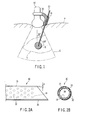
- FIG. 1 is a schematic diagram showing the use environment for the ultrasonically guided puncturing needle 30 according to the first embodiment of the present invention.
- reference numerals 10, 20, and 30 denote an ultrasonic probe, a puncturing guide, and the ultrasonically guided puncturing needle, respectively.
- Reference characters P and G denote a subject and an ultrasonic image.
- the ultrasonic probe 10 transmits and receives ultrasonic waves through a transmitting and receiving surface provided at a leading end of the ultrasonic probe 10 to the subject P in order to visualize the internal structure of the subject P.
- An ultrasonic image G of the subject P is displayed on a monitor (not shown). Here, the ultrasonic image G is drawn on the subject P in FIG. 1.
- the puncturing guide 20 is fixed to the ultrasonic probe 10 and has a guide hole 21 formed at a predetermined position.
- the ultrasonically guided puncturing needle 30 is inserted through the guide hole 21 so as to be movable forward and backward.
- the ultrasonically guided puncturing needle 30 is guided so as to have a fixed puncturing angle.
- the puncturing angle of the ultrasonically guided puncturing needle 30 is set at about 60°. That is, the ultrasonically guided puncturing needle 30 is stabbed while being inclined at about 30° to the axis of the ultrasonic probe 10 in an array direction.
- the ultrasonically guided puncturing needle 30 is not inclined in a lens direction.
- the ultrasonically guided puncturing needle 30 sucks or cauterizes a biotissue in a lesion site D or inject alcohol into the lesion site D, via its leading end.
- the lesion site D is assumed to be a cancer in the liver L.
- FIG. 2A is a schematic diagram of the ultrasonically guided puncturing needle 30 according to the first embodiment.
- FIG. 2B is a sectional view of the ultrasonically guided puncturing needle 30 according to the first embodiment.
- the ultrasonically guided puncturing needle 30 comprises a needle main body (needle-like member) 31.
- the needle main body 31 is formed to be cylindrical and its leading end stabbed in the subject P is reverse-tapered so as to prevent the biotissue from being caught.
- a metal material is used for the needle main body 31.
- a large number of holes 32 are formed in a peripheral wall of the needle main body 31 to allow the inside and outside of the needle main body 31 to communicate with each other.
- the shape of the hole 32 is not limited but the pitch intervals of the holes are preferably as small as possible. For example, laser machining is used to form holes 32.
- a film 33 is formed around an outer peripheral surface of the needle main body 31.
- the film 33 has a film thickness d equal to or smaller than the wavelength of an ultrasonic wave.
- the film 33 externally blocks the large number of holes 32 formed in the needle main body 31. This forms a plurality of air layers 34 in the needle main body 31 which are accessible to ultrasonic waves.
- the film 33 is preferably made of resin, which allows a film to be appropriately formed around the needle main body 31 and which is safe for living bodies.
- the air layers 34 are necessarily formed by the reduced adhesion at the boundary between the hole 32 and the film 33 resulting from the formation of a film 33.
- the operator applies the transmitting and receiving surface of the ultrasonic probe 10 to the subject P and starts transmitting and receiving an ultrasonic wave. This causes an ultrasonic image G of a region including the lesion site D to be displayed on the monitor (not shown).
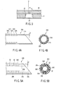
- FIG. 3 is a conceptual drawing showing that an ultrasonic wave is reflected by the air layer 34 according to the first embodiment.
- Ultrasonic waves transmitted by the ultrasonic probe 10 pass through a tissue in the subject P to reach the ultrasonically guided puncturing needle 30.
- An ultrasonic wave U which reached a portion of the film 33 corresponding to the hole 32 is transmitted through the film 33 and reflected by the boundary surface between the film 33 and the air layer 34 as shown in FIG. 3.
- An ultrasonic wave which reached a portion of the film 33 corresponding to the needle main body 31 is transmitted through the film 33 and reflected by the boundary surface between the film 33 and the needle main body 31.
- the ultrasonic wave reflected by the air layer 34 or needle main body 31 is transmitted through the film 33 and the tissue in the subject P again and then received by the ultrasonic probe 10.
- the air layer 34 and the subject P have greatly different acoustic impedances.
- the ultrasonic wave reflected by the air layer 34 thus has a very large intensity. Consequently, if the ultrasonically guided puncturing needle 30 comprises the large number of air layers 34 as in the case of the present embodiment, the amount of backscattering at the tip of the ultrasonically guided puncturing needle 30 increases to brightly show the ultrasonically guided puncturing needle 30 on the ultrasonic image G.
- the large number of holes 32 are formed in the peripheral wall of the needle main body 31.
- the air layers 34 are also provided in the needle main body 31 by blocking the holes 32 from the outside of the needle main body 31 with the film 33.
- the ultrasonically guided puncturing needle 30 is thus brightly shown even if the puncturing angle of the ultrasonically guided puncturing needle 30 is markedly different from 60°. Safe, reliable operations can also be performed without the need for special equipment or control.
- the present embodiment only requires the formation of a large number of holes 32 in the needle main body 31 and the formation of a film 33 around the outer peripheral surface of the needle main body 31.
- the ultrasonically guided puncturing needle according to the present embodiment can be obtained by a very simple manufacture process.
- the present embodiment has been described in conjunction with the puncturing angle in the array direction. Even if, for example, the ultrasonically guided puncturing needle 30 is greatly bent in the lens direction during the puncturing process, the amount of backscattering at the tip of the ultrasonically guided puncturing needle 30 increases to enable the ultrasonically guided puncturing needle 30 to be shown more brightly than in the prior art.
- FIG. 4A is a schematic diagram of the ultrasonically guided puncturing needle 30A according to a second embodiment of the present invention.
- FIG. 4B is a sectional view of the ultrasonically guided puncturing needle 30A according to the second embodiment.
- the ultrasonically guided puncturing needle 30A comprises a large number of concaves 32A and convexes 32D in an outer peripheral surface of a needle main body (needle-like member) 31A.
- the shape of the concave 32A and convex 32D is not limited but the pitch intervals are preferably as small as possible.
- the concaves 32A and the convexes 32D are formed by, for example, sand blasting. Concaves and convexes on an inner peripheral surface can be formed by rotationally inserting a screw-like machine having an outer diameter equal to the inner diameter of the needle main body 31A into the needle main body 31A.
- a film 33A is formed around the outer peripheral surface of the needle main body 31A.
- the film 33A externally blocks the large number of concaves 32A formed in the outer peripheral surface of the needle main body 31A.
- a small void is formed inside each concave 32A.
- the distance d from the surface of the film 33A to the void is set equal to or shorter than the wavelength of ultrasonic waves when by conditions are set for the formation of a film 33A. This forms a large number of air layers 34A in the concaves 32A which consist of the voids and which are reachable by supersonic waves.
- the large number of concaves 32A are formed around the outer peripheral surface of the needle main body 31A.
- the air layers 34A are provided in the needle main body 31A by blocking the large number of concaves 32A from the outside of the needle main body 31A with the film 33A.
- the ultrasonically guided puncturing needle 30A is thus brightly shown even if the puncturing angle of the ultrasonically guided puncturing needle 30A is markedly different from 60°. Safe, reliable operations can also be performed without the need for special equipment or control. Moreover, the ultrasonically guided puncturing needle 30A according to the present embodiment can be obtained by a very simple manufacture process.
- the present embodiment uses the air layers 34A to increase the amount of backscattering at the tip of the ultrasonically guided puncturing needle 30A.
- the present invention is not limited to this. Any layer, for example, a vacuum layer, may be used provided that it reflects ultrasonic waves well. The vacuum layer is easily obtained provided that a film 33A is formed around the needle main body 31A in a vacuum environment.
- FIG. 5A is a schematic diagram of the ultrasonically guided puncturing needle 30B according to a second embodiment of the present invention.
- FIG. 5B is a sectional view of the ultrasonically guided puncturing needle 30B according to the second embodiment.
- the ultrasonically guided puncturing needle 308 comprises the large number of holes 32 in an outer peripheral surface of a needle main body 31B as in the case of the first embodiment.
- a first and second films 33a and 33b are sequentially stacked around the outer peripheral surface of the needle main body 31B.
- the first film 33a gets into the holes 32, formed in the needle main body 31B, and has concaves formed in its outer peripheral surface at positions corresponding to the holes 32.
- the second film 33b has a film thickness d equal to or shorter than the wavelength of ultrasonic waves and almost completely cylindrical; the shape of the second film 33b does not coincide with the outer peripheral surface of the first film 33a. This forms a large number of air layers 34B outside the needle main body 31B at positions corresponding to the holes 32; the air layers 34B are blocked by the first and second film 33a and 33b.
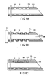
- FIGS. 6A to 6C is a process diagram showing the process of manufacturing an ultrasonically guided puncturing needle 30B according to the second embodiment.
- a first film 33a is formed around the outer peripheral surface of the needle main body 31B.
- a base end of the needle main body 31B is closed by a closing member A. Air is sucked from the needle main body 31B through a leading end of the needle main body 31B. This causes the first film 33a to be sucked into the holes 32 to form concaves in the outer peripheral surface of the first film 33a.
- a second film 33b is formed around the outer peripheral surface of the first film 33a. This forms a large number of air layers 34B around the outer peripheral surface of the needle main body 31B at positions corresponding to the holes 32; the air layers 34B are blocked by the first and second films 33a and 33b.
- the large number of holes 32 are formed in the peripheral wall of the needle main body 31B.
- the first and second films 33a and 33b are stacked on the outer peripheral surface of the needle main body 31B.
- the air layers 34B are provided between the first and second films 33a and 33b to reflect ultrasonic waves.
- the ultrasonically guided puncturing needle 30B is thus brightly shown even if the puncturing angle of the ultrasonically guided puncturing needle 30A is markedly different from 60°. Safe, reliable operations can also be performed without the need for special equipment or control. Moreover, the ultrasonically guided puncturing needle 30B according to the present invention can be obtained by a very simple manufacture process.
- the present embodiment uses the air layers 34B to increase the amount of backscattering at the tip of the ultrasonically guided puncturing needle 30B.
- the present invention is not limited to this. Any layer, for example, a vacuum layer, may be used provided that it reflects ultrasonic waves well. The vacuum layer is easily obtained provided that a second film 33b is formed around the needle main body 31B in a vacuum environment.
- the present invention is not limited to the above embodiments proper.
- the components of the embodiments may be varied without departing from the spirit of the present invention.
- Various inventions can also be formed by appropriately combining a plurality of the components disclosed in the above embodiments. For example, some of the components shown in the embodiments may be deleted. Components of different embodiments may also be appropriately combined together.
Landscapes
- Health & Medical Sciences (AREA)
- Life Sciences & Earth Sciences (AREA)
- Surgery (AREA)
- Animal Behavior & Ethology (AREA)
- Public Health (AREA)
- Engineering & Computer Science (AREA)
- Biomedical Technology (AREA)
- Heart & Thoracic Surgery (AREA)
- Medical Informatics (AREA)
- Molecular Biology (AREA)
- Pathology (AREA)
- General Health & Medical Sciences (AREA)
- Nuclear Medicine, Radiotherapy & Molecular Imaging (AREA)
- Veterinary Medicine (AREA)
- Physics & Mathematics (AREA)
- Biophysics (AREA)
- Radiology & Medical Imaging (AREA)
- Anesthesiology (AREA)
- Media Introduction/Drainage Providing Device (AREA)
- Surgical Instruments (AREA)
- Ultra Sonic Daignosis Equipment (AREA)
- Finger-Pressure Massage (AREA)
Abstract
Description
- The present invention relates to an ultrasonically guided puncturing needle that is stabbed in a subject being irradiated with ultrasonic waves for diagnosis or treatment.
- What is called ultrasonically guided paracentesis is known in which an operator subjects a lesion site such as tumor which has been found by ultrasonography to puncturing, aspiration biopsy, or cauterization while checking an ultrasonic image of the lesion site. This technique is known to maximize the amount of scattering of ultrasonic waves when the puncturing angle of a needle is set at 60° with respect to an ultrasonic radiation angle. Thus, when the puncturing angle of the needle is not 60°, the amount of backscattering of ultrasonic waves at the tip of the needle may decrease to prevent the ultrasonic waves from being appropriately received. To obtain clear needle tip echoes, it is thus necessary to set the puncturing angle of the needle as close to 60° as possible.
- Thus, when this technique is used, a puncturing guide is used which guides the direction in which the needle is inserted. The puncturing guide is commonly fixed to an ultrasonic probe to set the puncturing angle of the needle at 60° with respect to the ultrasonic irradiation angle.
- However, even though the inserting direction of the needle is guided using the puncturing guide, the needle itself may be bent during the puncturing process to prevent the puncturing angle from being maintained at 60° near the lesion site. In other cases, another angle may have to be chosen depending on the positional relationship between the ultrasonic probe and the lesion. In the above case, the amount of backscattering of the ultrasonic wave at the needle tip may decrease to make needle tip echoes unclear.
- In recent years, a technique relating to a film has been developed in which a gas is used as a reflection source for ultrasonic waves in order to obtain clear needle tip echoes. The gas provides an acoustic impedance significantly different from that of living bodies and can thus be very effectively used as a reflection source for ultrasonic waves (see, for example,
PCT National Publication No. 2001-504101 - However, a problem with the technique described in
PCT National Publication No. 2001-504101 is that manufacture of the film is very complicated, thus requiring high manufacture costs. - The present invention provides an ultrasonically guided puncturing needle that enables a safe, reliable technique for ultrasonically guided paracentesis to be realized without the need for special equipment or control.
- An ultrasonically guided puncturing needle according to an aspect of the present invention is configured as described below.
- (1) An ultrasonically guided puncturing needle stabbed in a subject being irradiated with an ultrasonic wave, the needle comprising a cylindrical needle-like member having concaves and convexes formed on a peripheral surface of the needle-like member to reflect the ultrasonic wave and a film formed on the peripheral surface on which the concaves and convexes are formed.
- (2) The ultrasonically guided puncturing needle set forth in (1), wherein a space which is either a gas layer or a vacuum layer is formed in each of the concaves.
- (3) The ultrasonically guided puncturing needle set forth in (2), wherein the concaves and convexes are formed on an outer peripheral surface of the needle-like member, and a distance from an outer surface of the film formed on the outer peripheral surface to the space is equal to or shorter than the wavelength of the ultrasonic wave.
- (4) An ultrasonically guided puncturing needle stabbed in a subject being irradiated with an ultrasonic wave, the needle comprising a cylindrical needle-like member having a plurality of holes in a peripheral wall and a film which blocks the plurality of the holes.
- (5) The ultrasonically guided puncturing needle set forth in (4), wherein a space which is either a gas layer or a vacuum layer is formed in each of the holes.
- (6) The ultrasonically guided puncturing needle set forth in (4), wherein the film is formed on an outer peripheral surface of the needle-like member, and
a distance from an outer surface of the film to the space is equal to or shorter than the wavelength of the ultrasonic wave. - (7) The ultrasonically guided puncturing needle set forth in (4), wherein the film blocks the plurality of the holes from an outside of the needle-like member.
- (8) The ultrasonically guided puncturing needle set forth in (4), wherein the film blocks the plurality of the holes from an inside of the needle-like member.
- (9) An ultrasonically guided puncturing needle stabbed in a subject being irradiated with an ultrasonic wave, the needle comprising a cylindrical needle-like member having a plurality of concaves on an outer peripheral surface and a film which blocks the plurality of the concaves from an outside of the needle-like member.
- (10) An ultrasonically guided puncturing needle stabbed in a subject being irradiated with an ultrasonic wave, the needle comprising a cylindrical needle-like member and at least two films stacked on a peripheral surface of the needle-like member, wherein a space which is either a vacuum layer or a gas layer is formed between the two films.
- (11) The ultrasonically guided puncturing needle set forth in (10), wherein a distance from an outer surface of the outermost one of the at least two films to the space is equal to or shorter than the wavelength of the ultrasonic wave.
- The present invention can realize a safe, reliable technique for ultrasonically guided paracentesis without the need for special equipment or control.
- This summary of the invention does not necessarily describe all necessary features so that the invention may also be a sub-combination of these described features.
- The invention can be more fully understood from the following detailed description when taken in conjunction with the accompanying drawings, in which:
- FIG. 1 is a schematic diagram showing a use environment for an ultrasonically guided puncturing needle according to a first embodiment of the present invention;
- FIG. 2A is a schematic diagram of the ultrasonically guided puncturing needle according to the first embodiment;
- FIG. 2B is a sectional view of the ultrasonically guided puncturing needle according to the first embodiment;
- FIG. 3 is a conceptual drawing showing that an ultrasonic wave is reflected by an air layer according to the first embodiment;
- FIG. 4A is a schematic diagram of an ultrasonically guided puncturing needle according to a second embodiment of the present invention;
- FIG. 4B is a sectional view of the ultrasonically guided puncturing needle according to the second embodiment of the present invention;
- FIG. 5A is a schematic diagram of the ultrasonically guided puncturing needle according to a third embodiment of the present invention;
- FIG. 5B is a sectional view of the ultrasonically guided puncturing needle according to the third embodiment of the present invention;
- FIG. 6A is a process diagram showing a process of manufacturing an ultrasonically guided puncturing needle according to the third embodiment;
- FIG. 6B is a process diagram showing the process of manufacturing an ultrasonically guided puncturing needle according to the third embodiment; and
- FIG. 6C is a process diagram showing the process of manufacturing an ultrasonically guided puncturing needle according to the third embodiment.
- A first to third embodiments of the present invention will be described with reference to the drawings.
- First, a use environment for an ultrasonically guided
puncturing needle 30 will be described. FIG. 1 is a schematic diagram showing the use environment for the ultrasonically guidedpuncturing needle 30 according to the first embodiment of the present invention. In FIG. 1,reference numerals - The
ultrasonic probe 10 transmits and receives ultrasonic waves through a transmitting and receiving surface provided at a leading end of theultrasonic probe 10 to the subject P in order to visualize the internal structure of the subject P. An ultrasonic image G of the subject P is displayed on a monitor (not shown). Here, the ultrasonic image G is drawn on the subject P in FIG. 1. - The
puncturing guide 20 is fixed to theultrasonic probe 10 and has aguide hole 21 formed at a predetermined position. The ultrasonically guidedpuncturing needle 30 is inserted through theguide hole 21 so as to be movable forward and backward. The ultrasonically guidedpuncturing needle 30 is guided so as to have a fixed puncturing angle. The puncturing angle of the ultrasonically guidedpuncturing needle 30 is set at about 60°. That is, the ultrasonically guidedpuncturing needle 30 is stabbed while being inclined at about 30° to the axis of theultrasonic probe 10 in an array direction. The ultrasonically guidedpuncturing needle 30 is not inclined in a lens direction. - The ultrasonically guided
puncturing needle 30 sucks or cauterizes a biotissue in a lesion site D or inject alcohol into the lesion site D, via its leading end. In the present embodiment, the lesion site D is assumed to be a cancer in the liver L. - Now, the configuration of the ultrasonically guided puncturing
needle 30 will be described with reference to FIGS. 2A and 2B. FIG. 2A is a schematic diagram of the ultrasonically guided puncturingneedle 30 according to the first embodiment. FIG. 2B is a sectional view of the ultrasonically guided puncturingneedle 30 according to the first embodiment. - As shown in FIGS. 2A and 2B, the ultrasonically guided puncturing
needle 30 comprises a needle main body (needle-like member) 31. The needlemain body 31 is formed to be cylindrical and its leading end stabbed in the subject P is reverse-tapered so as to prevent the biotissue from being caught. A metal material is used for the needlemain body 31. - A large number of
holes 32 are formed in a peripheral wall of the needlemain body 31 to allow the inside and outside of the needlemain body 31 to communicate with each other. The shape of thehole 32 is not limited but the pitch intervals of the holes are preferably as small as possible. For example, laser machining is used to form holes 32. - A
film 33 is formed around an outer peripheral surface of the needlemain body 31. Thefilm 33 has a film thickness d equal to or smaller than the wavelength of an ultrasonic wave. Thefilm 33 externally blocks the large number ofholes 32 formed in the needlemain body 31. This forms a plurality of air layers 34 in the needlemain body 31 which are accessible to ultrasonic waves. In order to prevent the needle from being markedly hindered from being inserted into the living body owing to the presence of theholes 32 formed in the needlemain body 31, thefilm 33 is preferably made of resin, which allows a film to be appropriately formed around the needlemain body 31 and which is safe for living bodies. The air layers 34 are necessarily formed by the reduced adhesion at the boundary between thehole 32 and thefilm 33 resulting from the formation of afilm 33. - Now, the usage of the ultrasonically guided puncturing
needle 30 will be described. The operator applies the transmitting and receiving surface of theultrasonic probe 10 to the subject P and starts transmitting and receiving an ultrasonic wave. This causes an ultrasonic image G of a region including the lesion site D to be displayed on the monitor (not shown). - The operator then inserts the ultrasonically guided puncturing
needle 30 into theguide hole 21 in the puncturingguide 20. While viewing the ultrasonic image G, the operator stabs the ultrasonically guided puncturingneedle 30 in the subject P. The ultrasonically guided puncturingneedle 30 stabbed in the subject P is shown in the ultrasonic image G as shown in FIG. 1. Accordingly, while viewing the ultrasonically guided puncturingneedle 30 shown in the ultrasonic image G, the operator aligns the leading end of the ultrasonically guided puncturingneedle 30 with the lesion site D. The operator then performs an operation such as sucking or cauterization of a biotissue in the lesion site D, injection of alcohol into the lesion site D, or the like. After the operation, the operator removes the ultrasonically guided puncturingneedle 30 from the subject P while viewing the ultrasonic image G. The ultrasonically guided paracetesis is thus finished. - Now, display of the ultrasonically guided puncturing
needle 30 will be described with reference to FIG. 3. FIG. 3 is a conceptual drawing showing that an ultrasonic wave is reflected by theair layer 34 according to the first embodiment. Ultrasonic waves transmitted by theultrasonic probe 10 pass through a tissue in the subject P to reach the ultrasonically guided puncturingneedle 30. An ultrasonic wave U which reached a portion of thefilm 33 corresponding to thehole 32 is transmitted through thefilm 33 and reflected by the boundary surface between thefilm 33 and theair layer 34 as shown in FIG. 3. An ultrasonic wave which reached a portion of thefilm 33 corresponding to the needlemain body 31 is transmitted through thefilm 33 and reflected by the boundary surface between thefilm 33 and the needlemain body 31. The ultrasonic wave reflected by theair layer 34 or needlemain body 31 is transmitted through thefilm 33 and the tissue in the subject P again and then received by theultrasonic probe 10. - The
air layer 34 and the subject P have greatly different acoustic impedances. The ultrasonic wave reflected by theair layer 34 thus has a very large intensity. Consequently, if the ultrasonically guided puncturingneedle 30 comprises the large number of air layers 34 as in the case of the present embodiment, the amount of backscattering at the tip of the ultrasonically guided puncturingneedle 30 increases to brightly show the ultrasonically guided puncturingneedle 30 on the ultrasonic image G. - In the present embodiment, the large number of
holes 32 are formed in the peripheral wall of the needlemain body 31. The air layers 34 are also provided in the needlemain body 31 by blocking theholes 32 from the outside of the needlemain body 31 with thefilm 33. - This increases the amount of backscattering at the tip of the ultrasonically guided puncturing
needle 30. The ultrasonically guided puncturingneedle 30 is thus brightly shown even if the puncturing angle of the ultrasonically guided puncturingneedle 30 is markedly different from 60°. Safe, reliable operations can also be performed without the need for special equipment or control. - Moreover, the present embodiment only requires the formation of a large number of
holes 32 in the needlemain body 31 and the formation of afilm 33 around the outer peripheral surface of the needlemain body 31. The ultrasonically guided puncturing needle according to the present embodiment can be obtained by a very simple manufacture process. - The present embodiment has been described in conjunction with the puncturing angle in the array direction. Even if, for example, the ultrasonically guided puncturing
needle 30 is greatly bent in the lens direction during the puncturing process, the amount of backscattering at the tip of the ultrasonically guided puncturingneedle 30 increases to enable the ultrasonically guided puncturingneedle 30 to be shown more brightly than in the prior art. - First, the configuration of an ultrasonically guided
puncturing needle 30A will be described with reference to FIGS. 4A and 4B. FIG. 4A is a schematic diagram of the ultrasonically guided puncturingneedle 30A according to a second embodiment of the present invention. FIG. 4B is a sectional view of the ultrasonically guided puncturingneedle 30A according to the second embodiment. - As shown in FIGS. 4A and 4B, the ultrasonically guided puncturing
needle 30A according to the present embodiment comprises a large number ofconcaves 32A andconvexes 32D in an outer peripheral surface of a needle main body (needle-like member) 31A. The shape of the concave 32A and convex 32D is not limited but the pitch intervals are preferably as small as possible. Theconcaves 32A and theconvexes 32D are formed by, for example, sand blasting. Concaves and convexes on an inner peripheral surface can be formed by rotationally inserting a screw-like machine having an outer diameter equal to the inner diameter of the needlemain body 31A into the needlemain body 31A. - A
film 33A is formed around the outer peripheral surface of the needlemain body 31A. Thefilm 33A externally blocks the large number ofconcaves 32A formed in the outer peripheral surface of the needlemain body 31A. A small void is formed inside each concave 32A. The distance d from the surface of thefilm 33A to the void is set equal to or shorter than the wavelength of ultrasonic waves when by conditions are set for the formation of afilm 33A. This forms a large number ofair layers 34A in theconcaves 32A which consist of the voids and which are reachable by supersonic waves. - In the present embodiment, the large number of
concaves 32A are formed around the outer peripheral surface of the needlemain body 31A. The air layers 34A are provided in the needlemain body 31A by blocking the large number ofconcaves 32A from the outside of the needlemain body 31A with thefilm 33A. - This increases the amount of backscattering at the tip of the ultrasonically guided puncturing
needle 30A. The ultrasonically guided puncturingneedle 30A is thus brightly shown even if the puncturing angle of the ultrasonically guided puncturingneedle 30A is markedly different from 60°. Safe, reliable operations can also be performed without the need for special equipment or control. Moreover, the ultrasonically guided puncturingneedle 30A according to the present embodiment can be obtained by a very simple manufacture process. - The present embodiment uses the air layers 34A to increase the amount of backscattering at the tip of the ultrasonically guided puncturing
needle 30A. However, the present invention is not limited to this. Any layer, for example, a vacuum layer, may be used provided that it reflects ultrasonic waves well. The vacuum layer is easily obtained provided that afilm 33A is formed around the needlemain body 31A in a vacuum environment. - First, the configuration of an ultrasonically guided
puncturing needle 30B will be described with reference to FIGS. 5A and 5B. FIG. 5A is a schematic diagram of the ultrasonically guided puncturingneedle 30B according to a second embodiment of the present invention. FIG. 5B is a sectional view of the ultrasonically guided puncturingneedle 30B according to the second embodiment. - As shown in FIGS. 5A and 58, the ultrasonically guided puncturing needle 308 according to the present embodiment comprises the large number of
holes 32 in an outer peripheral surface of a needlemain body 31B as in the case of the first embodiment. - A first and
second films main body 31B. Thefirst film 33a gets into theholes 32, formed in the needlemain body 31B, and has concaves formed in its outer peripheral surface at positions corresponding to theholes 32. Thesecond film 33b has a film thickness d equal to or shorter than the wavelength of ultrasonic waves and almost completely cylindrical; the shape of thesecond film 33b does not coincide with the outer peripheral surface of thefirst film 33a. This forms a large number of air layers 34B outside the needlemain body 31B at positions corresponding to theholes 32; the air layers 34B are blocked by the first andsecond film - Now, with reference to FIGS. 6A to 6C, description will be given of a process of manufacturing an ultrasonically guided
puncturing needle 30B. FIGS. 6A to 6C is a process diagram showing the process of manufacturing an ultrasonically guided puncturingneedle 30 30B according to the second embodiment. - As shown in FIG. 6A, a
first film 33a is formed around the outer peripheral surface of the needlemain body 31B. Then, as shown in FIG. 6B, a base end of the needlemain body 31B is closed by a closing member A. Air is sucked from the needlemain body 31B through a leading end of the needlemain body 31B. This causes thefirst film 33a to be sucked into theholes 32 to form concaves in the outer peripheral surface of thefirst film 33a. Then, as shown in FIG. 6C, asecond film 33b is formed around the outer peripheral surface of thefirst film 33a. This forms a large number of air layers 34B around the outer peripheral surface of the needlemain body 31B at positions corresponding to theholes 32; the air layers 34B are blocked by the first andsecond films - In the present embodiment, the large number of
holes 32 are formed in the peripheral wall of the needlemain body 31B. The first andsecond films main body 31B. The air layers 34B are provided between the first andsecond films - This increases the amount of backscattering at the tip of the ultrasonically guided puncturing
needle 30B. The ultrasonically guided puncturingneedle 30B is thus brightly shown even if the puncturing angle of the ultrasonically guided puncturingneedle 30A is markedly different from 60°. Safe, reliable operations can also be performed without the need for special equipment or control. Moreover, the ultrasonically guided puncturingneedle 30B according to the present invention can be obtained by a very simple manufacture process. - The present embodiment uses the air layers 34B to increase the amount of backscattering at the tip of the ultrasonically guided puncturing
needle 30B. However, the present invention is not limited to this. Any layer, for example, a vacuum layer, may be used provided that it reflects ultrasonic waves well. The vacuum layer is easily obtained provided that asecond film 33b is formed around the needlemain body 31B in a vacuum environment. - The present invention is not limited to the above embodiments proper. In implementation, the components of the embodiments may be varied without departing from the spirit of the present invention. Various inventions can also be formed by appropriately combining a plurality of the components disclosed in the above embodiments. For example, some of the components shown in the embodiments may be deleted. Components of different embodiments may also be appropriately combined together.
- It is explicitly stated that all features disclosed in the description and/or the claims are intended to be disclosed separately and independently from each other for the purpose of original disclosure as well as for the purpose of restricting the claimed invention independent of the composition of the features in the embodiments and/or the claims. It is explicitly stated that all value ranges or indications of groups of entities disclose every possible intermediate value or intermediate entity for the purpose of original disclosure as well as for the purpose of restricting the claimed invention, in particular as limits of value ranges.
Claims (11)
- An ultrasonically guided puncturing needle (30A) stabbed in a subject (P) being irradiated with an ultrasonic wave, the needle (30A) characterized by comprising:a cylindrical needle-like member (31A) having concaves (32A) and convexes (32D) formed on a peripheral surface of the needle-like member (31A) to reflect the ultrasonic wave; anda film (33A) formed on the peripheral surface on which the concaves (32A) and convexes (32D) are formed.
- The ultrasonically guided puncturing needle (30A) according to claim 1, characterized in that a space which is either a gas layer (34A) or a vacuum layer is formed in each of the concaves (32A).
- The ultrasonically guided puncturing needle (30A) according to claim 2, characterized in that the concaves (32A) and convexes (32D) are formed on an outer peripheral surface of the needle-like member (31A), and
a distance from an outer surface of the film (33A) formed on the outer peripheral surface to the space is equal to or shorter than the wavelength of the ultrasonic wave. - An ultrasonically guided puncturing needle (30) stabbed in a subject (P) being irradiated with an ultrasonic wave, the needle (30) characterized by comprising:a cylindrical needle-like member (31) having a plurality of holes (32) in a peripheral wall; anda film (33) which blocks the plurality of the holes (32).
- The ultrasonically guided puncturing needle (30) according to claim 4, characterized in that a space which is either a gas layer (34) or a vacuum layer is formed in each of the holes (32).
- The ultrasonically guided puncturing needle (30) according to claim 5, characterized in that the film (33) is formed on an outer peripheral surface of the needle-like member (31), and
a distance from an outer surface of the film (33) to the space is equal to or shorter than the wavelength of the ultrasonic wave. - The ultrasonically guided puncturing needle (30) according to claim 4, characterized in that the film (33) blocks the plurality of the holes (32) from an outside of the needle-like member (31).
- The ultrasonically guided puncturing needle (30) according to claim 4, characterized in that the film (33) blocks the plurality of the holes (32) from an inside of the needle-like member (31).
- An ultrasonically guided puncturing needle (30A) stabbed in a subject (P) being irradiated with an ultrasonic wave, the needle (30A) characterized by comprising:a cylindrical needle-like member (31A) having a plurality of concaves (32A) on an outer peripheral surface; anda film (33A) which blocks the plurality of the concaves (32A) from an outside of the needle-like member (31A).
- An ultrasonically guided puncturing needle (30B) stabbed in a subject (P) being irradiated with an ultrasonic wave, the needle (30B) characterized by comprising:a cylindrical needle-like member (31B); andat least two films (33a, 33b) stacked on a peripheral surface of the needle-like member (31B),wherein a space which is either a vacuum layer or a gas layer (34B) is formed between the two films (33a, 33b).
- The ultrasonically guided puncturing needle (30B) according to claim 10, characterized in that a distance from an outer surface of the outermost one (33b) of the at least two films (33a, 33b) to the space is equal to or shorter than the wavelength of the ultrasonic wave.
Applications Claiming Priority (1)
| Application Number | Priority Date | Filing Date | Title |
|---|---|---|---|
| JP2005099445A JP2006271874A (en) | 2005-03-30 | 2005-03-30 | Ultrasound guided puncture needle |
Publications (4)
| Publication Number | Publication Date |
|---|---|
| EP1707134A2 true EP1707134A2 (en) | 2006-10-04 |
| EP1707134A3 EP1707134A3 (en) | 2006-10-25 |
| EP1707134B1 EP1707134B1 (en) | 2008-10-15 |
| EP1707134B9 EP1707134B9 (en) | 2012-02-15 |
Family
ID=36254640
Family Applications (1)
| Application Number | Title | Priority Date | Filing Date |
|---|---|---|---|
| EP06005638A Expired - Fee Related EP1707134B9 (en) | 2005-03-30 | 2006-03-20 | Ultrasonically guided puncturing needle |
Country Status (5)
| Country | Link |
|---|---|
| US (2) | US20060241489A1 (en) |
| EP (1) | EP1707134B9 (en) |
| JP (1) | JP2006271874A (en) |
| CN (1) | CN1839769A (en) |
| DE (1) | DE602006003113D1 (en) |
Cited By (4)
| Publication number | Priority date | Publication date | Assignee | Title |
|---|---|---|---|---|
| WO2008062451A3 (en) * | 2006-09-07 | 2008-07-10 | Gautam Allahbadia | Echogenic surface for surgical instrument |
| WO2008150733A1 (en) * | 2007-06-04 | 2008-12-11 | Medtronic, Inc. | Percutaneous needle guide and methods of use |
| EP3413815A4 (en) * | 2016-02-08 | 2019-10-30 | Injectimed, Inc. | ECHOGENIC NEEDLES AND METHOD FOR MANUFACTURING NEEDLE NEEDLES |
| US10722167B2 (en) | 2009-09-17 | 2020-07-28 | Mauna Kea Technologies | Method, an optical probe and a confocal microscopy system for inspecting a solid organ |
Families Citing this family (17)
| Publication number | Priority date | Publication date | Assignee | Title |
|---|---|---|---|---|
| JP2006271874A (en) * | 2005-03-30 | 2006-10-12 | Toshiba Corp | Ultrasound guided puncture needle |
| WO2007013130A1 (en) * | 2005-07-25 | 2007-02-01 | Hakko Co., Ltd. | Ultrasonic piercing needle |
| JP5552050B2 (en) * | 2008-06-27 | 2014-07-16 | テルモ株式会社 | Indwelling needle |
| WO2010012023A1 (en) * | 2008-07-29 | 2010-02-04 | Coco Research Pty Ltd | An echogenic medical needle |
| DE102010016448A1 (en) * | 2010-04-14 | 2011-10-20 | Aesculap Ag | Orthopedic fixation system and target device for such a fixation system |
| FR2978657B1 (en) * | 2011-08-03 | 2013-08-30 | Echosens | METHOD FOR THE REAL-TIME DETERMINATION OF A PROBABILITY OF THE PRESENCE OF A TARGET BIOLOGICAL TISSUE WITH RESPECT TO AN ULTRASONIC TRANSDUCER |
| WO2013146310A1 (en) * | 2012-03-28 | 2013-10-03 | テルモ株式会社 | Puncture instrument assembly |
| WO2014045677A1 (en) * | 2012-09-21 | 2014-03-27 | オリンパスメディカルシステムズ株式会社 | Biopsy needle and biopsy system |
| JP6263254B2 (en) | 2013-03-14 | 2018-01-17 | マフィン・インコーポレイテッドMuffin Incorporated | Echogenic surface using Lulaw's triangle |
| JP6328993B2 (en) * | 2014-05-12 | 2018-05-23 | 株式会社共伸 | Medical needles used under observation with an ultrasound diagnostic device |
| CN104189973B (en) * | 2014-09-16 | 2016-09-07 | 上海市同济医院 | A kind of nerve block device being beneficial to ultrasonic guidance |
| US11331070B2 (en) | 2015-12-31 | 2022-05-17 | Koninklijke Philips N.V. | System and method for probe calibration and interventional acoustic imaging |
| CN107343812A (en) * | 2016-05-05 | 2017-11-14 | 上海安久生物科技有限公司 | Ultrasound guided puncture pin and preparation method |
| US20190388062A1 (en) * | 2018-06-20 | 2019-12-26 | Microtech Medical Technologies, Ltd. | Apparatus, System, and Method for Increasing Object Visibility |
| CN109730750A (en) * | 2018-12-13 | 2019-05-10 | 南昌大学第二附属医院 | A kind of Multifunctional needle knife |
| CN112914697B (en) * | 2021-03-30 | 2022-06-07 | 南昌大学第二附属医院 | Enhanced developing puncture needle for ultrasonically guiding nerve block |
| JP7784246B2 (en) | 2021-07-16 | 2025-12-11 | キヤノンメディカルシステムズ株式会社 | Ultrasound probe and ultrasound probe puncture adapter |
Family Cites Families (26)
| Publication number | Priority date | Publication date | Assignee | Title |
|---|---|---|---|---|
| DE2425724C3 (en) * | 1974-05-28 | 1979-09-27 | Siemens Ag, 1000 Berlin Und 8000 Muenchen | Puncture cannula |
| US4401124A (en) * | 1981-08-13 | 1983-08-30 | Technicare Corporation | Reflection enhancement of a biopsy needle |
| US4582061A (en) * | 1981-11-18 | 1986-04-15 | Indianapolis Center For Advanced Research, Inc. | Needle with ultrasonically reflective displacement scale |
| US4583061A (en) * | 1984-06-01 | 1986-04-15 | Raytheon Company | Radio frequency power divider/combiner networks |
| JPH0238726Y2 (en) * | 1986-12-30 | 1990-10-18 | ||
| US4853061A (en) * | 1987-05-05 | 1989-08-01 | Uniroyal Plastics Company, Inc. | Polyurethane adhesive thermoforming lamination process employing water-based |
| US5048530A (en) * | 1988-08-17 | 1991-09-17 | Robert Hurwitz | Method of using an amniocentesis needle with improved sonographic visibility |
| US5289831A (en) * | 1989-03-09 | 1994-03-01 | Vance Products Incorporated | Surface-treated stent, catheter, cannula, and the like |
| JPH0373113U (en) * | 1989-11-21 | 1991-07-23 | ||
| US5490521A (en) * | 1993-08-31 | 1996-02-13 | Medtronic, Inc. | Ultrasound biopsy needle |
| JP3171525B2 (en) * | 1994-04-14 | 2001-05-28 | 康雄 真島 | Medical puncture needle |
| US5766135A (en) * | 1995-03-08 | 1998-06-16 | Terwilliger; Richard A. | Echogenic needle tip |
| US5769795A (en) * | 1995-03-08 | 1998-06-23 | Terwilliger; Richard A. | Echogenic needle |
| US6106473A (en) * | 1996-11-06 | 2000-08-22 | Sts Biopolymers, Inc. | Echogenic coatings |
| US7229413B2 (en) * | 1996-11-06 | 2007-06-12 | Angiotech Biocoatings Corp. | Echogenic coatings with overcoat |
| US6053870A (en) * | 1997-11-08 | 2000-04-25 | Angiodynamics, Inc. | Ultrasonic visible surgical needle |
| US5967988A (en) * | 1998-04-08 | 1999-10-19 | Medtronic, Inc. | Catheter having echogenicity enhancement |
| GB9909801D0 (en) * | 1999-04-28 | 1999-06-23 | Btg Int Ltd | Ultrasound detectable instrument |
| US7014610B2 (en) * | 2001-02-09 | 2006-03-21 | Medtronic, Inc. | Echogenic devices and methods of making and using such devices |
| US6723052B2 (en) * | 2001-06-07 | 2004-04-20 | Stanley L. Mills | Echogenic medical device |
| GB0120645D0 (en) * | 2001-08-24 | 2001-10-17 | Smiths Group Plc | Medico-surgical devices |
| US6860856B2 (en) * | 2002-01-11 | 2005-03-01 | Scimed Life Systems, Inc. | Echogenic surface for enhanced ultasonic visibility |
| JP3890013B2 (en) * | 2002-12-05 | 2007-03-07 | オリンパス株式会社 | Ultrasound puncture needle |
| JP2006271874A (en) * | 2005-03-30 | 2006-10-12 | Toshiba Corp | Ultrasound guided puncture needle |
| US8382674B2 (en) * | 2005-12-02 | 2013-02-26 | Abbott Cardiovascular Systems Inc. | Visualization of a catheter viewed under ultrasound imaging |
| US8430863B2 (en) * | 2005-12-02 | 2013-04-30 | Abbott Cardiovascular Systems Inc. | Visualization of a catheter viewed under ultrasound imaging |
-
2005
- 2005-03-30 JP JP2005099445A patent/JP2006271874A/en active Pending
-
2006
- 2006-03-20 DE DE602006003113T patent/DE602006003113D1/en not_active Expired - Lifetime
- 2006-03-20 US US11/378,436 patent/US20060241489A1/en not_active Abandoned
- 2006-03-20 EP EP06005638A patent/EP1707134B9/en not_active Expired - Fee Related
- 2006-03-30 CN CNA2006100715692A patent/CN1839769A/en active Pending
-
2011
- 2011-04-27 US US13/095,521 patent/US20110201938A1/en not_active Abandoned
Cited By (6)
| Publication number | Priority date | Publication date | Assignee | Title |
|---|---|---|---|---|
| WO2008062451A3 (en) * | 2006-09-07 | 2008-07-10 | Gautam Allahbadia | Echogenic surface for surgical instrument |
| WO2008150733A1 (en) * | 2007-06-04 | 2008-12-11 | Medtronic, Inc. | Percutaneous needle guide and methods of use |
| US7976469B2 (en) | 2007-06-04 | 2011-07-12 | Medtronic, Inc. | Percutaneous needle guide |
| US8808187B2 (en) | 2007-06-04 | 2014-08-19 | Medtronic, Inc. | Percutaneous needle guide and methods of use |
| US10722167B2 (en) | 2009-09-17 | 2020-07-28 | Mauna Kea Technologies | Method, an optical probe and a confocal microscopy system for inspecting a solid organ |
| EP3413815A4 (en) * | 2016-02-08 | 2019-10-30 | Injectimed, Inc. | ECHOGENIC NEEDLES AND METHOD FOR MANUFACTURING NEEDLE NEEDLES |
Also Published As
| Publication number | Publication date |
|---|---|
| EP1707134B1 (en) | 2008-10-15 |
| US20060241489A1 (en) | 2006-10-26 |
| JP2006271874A (en) | 2006-10-12 |
| DE602006003113D1 (en) | 2008-11-27 |
| CN1839769A (en) | 2006-10-04 |
| EP1707134B9 (en) | 2012-02-15 |
| US20110201938A1 (en) | 2011-08-18 |
| EP1707134A3 (en) | 2006-10-25 |
Similar Documents
| Publication | Publication Date | Title |
|---|---|---|
| US20110201938A1 (en) | Ultrasonically guided puncturing needle | |
| JP3890013B2 (en) | Ultrasound puncture needle | |
| US20220151469A1 (en) | Photoacoustic and ultrasonic endoscopy system including a coaxially configured optical and electromagnetic rotary waveguide assembly and implementation method thereof | |
| US10905397B2 (en) | Array transducer-based side-scanning photoacoustic-ultrasonic endoscope | |
| Yasufuku et al. | Endobronchial ultrasound using a new convex probe: a preliminary study on surgically resected specimens | |
| US11612377B2 (en) | Image guided surgical methodology and system employing patient movement detection and correction | |
| CN104918555B (en) | Ultrasonic probe and alignment probe guiding piece system | |
| CA2517667C (en) | System for examining, mapping, diagnosing, and treating diseases of the prostate | |
| JP2001104315A (en) | Ultrasonic-guided paracentesis system device | |
| US20170055961A1 (en) | Echogenic Enhancement for a Needle | |
| US20200305927A1 (en) | Biopsy systems, ultrasound devices, and methods of use thereof | |
| WO1996027329A1 (en) | Echogenic needle | |
| JP2013505043A (en) | Method, optical probe and confocal microscope system for examining solid organs | |
| JP2019162416A (en) | Variable pitch flexible needle | |
| TWI529391B (en) | System and method for using photoacoustic effect | |
| US20220273274A1 (en) | Biopsy needle and tissue collecting device | |
| CN106132313B9 (en) | Rigid Lens Kit | |
| Hohert et al. | Feasibility of combined optical coherence tomography and autofluorescence imaging for visualization of needle biopsy placement | |
| CN109431547B (en) | Multi-frequency array ultrasound endoscopy system | |
| US20200179001A1 (en) | Medical needle comprising echogenic enhancements | |
| CN103052357A (en) | Ultrasound endoscope | |
| JP4339539B2 (en) | Ultrasound puncture needle | |
| CN209529081U (en) | Multimodal pancreaticocholangioimaging system | |
| JPH03228748A (en) | Supersonic reflecting body | |
| Nakamura et al. | Transurethral real-time scanner |
Legal Events
| Date | Code | Title | Description |
|---|---|---|---|
| PUAI | Public reference made under article 153(3) epc to a published international application that has entered the european phase |
Free format text: ORIGINAL CODE: 0009012 |
|
| PUAL | Search report despatched |
Free format text: ORIGINAL CODE: 0009013 |
|
| 17P | Request for examination filed |
Effective date: 20060320 |
|
| AK | Designated contracting states |
Kind code of ref document: A2 Designated state(s): AT BE BG CH CY CZ DE DK EE ES FI FR GB GR HU IE IS IT LI LT LU LV MC NL PL PT RO SE SI SK TR |
|
| AX | Request for extension of the european patent |
Extension state: AL BA HR MK YU |
|
| AK | Designated contracting states |
Kind code of ref document: A3 Designated state(s): AT BE BG CH CY CZ DE DK EE ES FI FR GB GR HU IE IS IT LI LT LU LV MC NL PL PT RO SE SI SK TR |
|
| AX | Request for extension of the european patent |
Extension state: AL BA HR MK YU |
|
| 17Q | First examination report despatched |
Effective date: 20070124 |
|
| AKX | Designation fees paid |
Designated state(s): DE NL |
|
| GRAP | Despatch of communication of intention to grant a patent |
Free format text: ORIGINAL CODE: EPIDOSNIGR1 |
|
| GRAS | Grant fee paid |
Free format text: ORIGINAL CODE: EPIDOSNIGR3 |
|
| GRAA | (expected) grant |
Free format text: ORIGINAL CODE: 0009210 |
|
| AK | Designated contracting states |
Kind code of ref document: B1 Designated state(s): DE NL |
|
| REF | Corresponds to: |
Ref document number: 602006003113 Country of ref document: DE Date of ref document: 20081127 Kind code of ref document: P |
|
| PLBE | No opposition filed within time limit |
Free format text: ORIGINAL CODE: 0009261 |
|
| STAA | Information on the status of an ep patent application or granted ep patent |
Free format text: STATUS: NO OPPOSITION FILED WITHIN TIME LIMIT |
|
| 26N | No opposition filed |
Effective date: 20090716 |
|
| PGFP | Annual fee paid to national office [announced via postgrant information from national office to epo] |
Ref country code: NL Payment date: 20110317 Year of fee payment: 6 |
|
| PGFP | Annual fee paid to national office [announced via postgrant information from national office to epo] |
Ref country code: DE Payment date: 20110316 Year of fee payment: 6 |
|
| REG | Reference to a national code |
Ref country code: NL Ref legal event code: V1 Effective date: 20121001 |
|
| REG | Reference to a national code |
Ref country code: DE Ref legal event code: R119 Ref document number: 602006003113 Country of ref document: DE Effective date: 20121002 |
|
| PG25 | Lapsed in a contracting state [announced via postgrant information from national office to epo] |
Ref country code: NL Free format text: LAPSE BECAUSE OF NON-PAYMENT OF DUE FEES Effective date: 20121001 |
|
| PG25 | Lapsed in a contracting state [announced via postgrant information from national office to epo] |
Ref country code: DE Free format text: LAPSE BECAUSE OF NON-PAYMENT OF DUE FEES Effective date: 20121002 |