EP1707028B1 - Kopfhörer - Google Patents
Kopfhörer Download PDFInfo
- Publication number
- EP1707028B1 EP1707028B1 EP05700779A EP05700779A EP1707028B1 EP 1707028 B1 EP1707028 B1 EP 1707028B1 EP 05700779 A EP05700779 A EP 05700779A EP 05700779 A EP05700779 A EP 05700779A EP 1707028 B1 EP1707028 B1 EP 1707028B1
- Authority
- EP
- European Patent Office
- Prior art keywords
- headphone
- electrical
- contacts
- wireless
- charging
- Prior art date
- Legal status (The legal status is an assumption and is not a legal conclusion. Google has not performed a legal analysis and makes no representation as to the accuracy of the status listed.)
- Expired - Lifetime
Links
Images





Classifications
-
- H—ELECTRICITY
- H04—ELECTRIC COMMUNICATION TECHNIQUE
- H04R—LOUDSPEAKERS, MICROPHONES, GRAMOPHONE PICK-UPS OR LIKE ACOUSTIC ELECTROMECHANICAL TRANSDUCERS; ELECTRIC HEARING AIDS; PUBLIC ADDRESS SYSTEMS
- H04R5/00—Stereophonic arrangements
- H04R5/033—Headphones for stereophonic communication
- H04R5/0335—Earpiece support, e.g. headbands or neckrests
-
- H—ELECTRICITY
- H02—GENERATION; CONVERSION OR DISTRIBUTION OF ELECTRIC POWER
- H02J—ELECTRIC POWER NETWORKS; CIRCUIT ARRANGEMENTS OR SYSTEMS FOR SUPPLYING OR DISTRIBUTING ELECTRIC POWER; SYSTEMS FOR STORING ELECTRIC ENERGY
- H02J7/00—Circuit arrangements for charging or discharging batteries or for supplying loads from batteries
- H02J7/70—Circuit arrangements for charging or discharging batteries or for supplying loads from batteries characterised by the mechanical construction
- H02J7/731—Circuit arrangements for charging or discharging batteries or for supplying loads from batteries characterised by the mechanical construction specially adapted for holding portable devices containing batteries
-
- H—ELECTRICITY
- H02—GENERATION; CONVERSION OR DISTRIBUTION OF ELECTRIC POWER
- H02J—ELECTRIC POWER NETWORKS; CIRCUIT ARRANGEMENTS OR SYSTEMS FOR SUPPLYING OR DISTRIBUTING ELECTRIC POWER; SYSTEMS FOR STORING ELECTRIC ENERGY
- H02J7/00—Circuit arrangements for charging or discharging batteries or for supplying loads from batteries
- H02J7/70—Circuit arrangements for charging or discharging batteries or for supplying loads from batteries characterised by the mechanical construction
- H02J7/751—Circuit arrangements for charging or discharging batteries or for supplying loads from batteries characterised by the mechanical construction concerning the insertion or the connection of the batteries
-
- H—ELECTRICITY
- H04—ELECTRIC COMMUNICATION TECHNIQUE
- H04R—LOUDSPEAKERS, MICROPHONES, GRAMOPHONE PICK-UPS OR LIKE ACOUSTIC ELECTROMECHANICAL TRANSDUCERS; ELECTRIC HEARING AIDS; PUBLIC ADDRESS SYSTEMS
- H04R1/00—Details of transducers, loudspeakers or microphones
- H04R1/10—Earpieces; Attachments therefor ; Earphones; Monophonic headphones
- H04R1/1025—Accumulators specially adapted for earpieces; Arrangements specially adapted for charging thereof
-
- H—ELECTRICITY
- H04—ELECTRIC COMMUNICATION TECHNIQUE
- H04R—LOUDSPEAKERS, MICROPHONES, GRAMOPHONE PICK-UPS OR LIKE ACOUSTIC ELECTROMECHANICAL TRANSDUCERS; ELECTRIC HEARING AIDS; PUBLIC ADDRESS SYSTEMS
- H04R1/00—Details of transducers, loudspeakers or microphones
- H04R1/10—Earpieces; Attachments therefor ; Earphones; Monophonic headphones
- H04R1/1008—Earpieces of the supra-aural or circum-aural type
-
- H—ELECTRICITY
- H04—ELECTRIC COMMUNICATION TECHNIQUE
- H04R—LOUDSPEAKERS, MICROPHONES, GRAMOPHONE PICK-UPS OR LIKE ACOUSTIC ELECTROMECHANICAL TRANSDUCERS; ELECTRIC HEARING AIDS; PUBLIC ADDRESS SYSTEMS
- H04R1/00—Details of transducers, loudspeakers or microphones
- H04R1/10—Earpieces; Attachments therefor ; Earphones; Monophonic headphones
- H04R1/1033—Cables or cables storage, e.g. cable reels
-
- H—ELECTRICITY
- H04—ELECTRIC COMMUNICATION TECHNIQUE
- H04R—LOUDSPEAKERS, MICROPHONES, GRAMOPHONE PICK-UPS OR LIKE ACOUSTIC ELECTROMECHANICAL TRANSDUCERS; ELECTRIC HEARING AIDS; PUBLIC ADDRESS SYSTEMS
- H04R1/00—Details of transducers, loudspeakers or microphones
- H04R1/10—Earpieces; Attachments therefor ; Earphones; Monophonic headphones
- H04R1/1058—Manufacture or assembly
- H04R1/1066—Constructional aspects of the interconnection between earpiece and earpiece support
-
- H—ELECTRICITY
- H04—ELECTRIC COMMUNICATION TECHNIQUE
- H04R—LOUDSPEAKERS, MICROPHONES, GRAMOPHONE PICK-UPS OR LIKE ACOUSTIC ELECTROMECHANICAL TRANSDUCERS; ELECTRIC HEARING AIDS; PUBLIC ADDRESS SYSTEMS
- H04R2420/00—Details of connection covered by H04R, not provided for in its groups
- H04R2420/07—Applications of wireless loudspeakers or wireless microphones
-
- Y—GENERAL TAGGING OF NEW TECHNOLOGICAL DEVELOPMENTS; GENERAL TAGGING OF CROSS-SECTIONAL TECHNOLOGIES SPANNING OVER SEVERAL SECTIONS OF THE IPC; TECHNICAL SUBJECTS COVERED BY FORMER USPC CROSS-REFERENCE ART COLLECTIONS [XRACs] AND DIGESTS
- Y02—TECHNOLOGIES OR APPLICATIONS FOR MITIGATION OR ADAPTATION AGAINST CLIMATE CHANGE
- Y02E—REDUCTION OF GREENHOUSE GAS [GHG] EMISSIONS, RELATED TO ENERGY GENERATION, TRANSMISSION OR DISTRIBUTION
- Y02E60/00—Enabling technologies; Technologies with a potential or indirect contribution to GHG emissions mitigation
- Y02E60/10—Energy storage using batteries
Definitions
- the present invention relates to a headphone having a one-sided curved temple suspension and an oblique Schallanwandlungsanordhung.
- the invention further relates to a wireless headset and a corresponding charging station for the wireless headset and finally a wireless headphone system.
- Wireless devices such as wireless headphones typically have a rechargeable battery.
- the wireless headphone In order to recharge this battery, the wireless headphone must have electrical contact surfaces, which can be designed to be strong or weakly resilient. Highly resilient contacts often have relatively long dimensions. For weakly resilient contacts, however, the contacts must be brought together form-fitting, so that the battery can be charged accordingly.
- EP 0 389 174 discloses a wireless headset and a charging station for a wireless headset having protruding rods. The rods are used as an electrical lead for the electrical charging contact of the wireless headphone.
- US 5,931,683 relates to a charger for wireless devices. The wireless device is equipped with at least one magnet and electrical charging contacts. When charging the device, the magnet attracts the mobile contacts of the charger.
- a wireless headset is provided with charging contacts in the headband and with at least one magnet in the headband.
- the invention also relates to a charging station for a corresponding wireless headphone.
- the charging station has rods as an electrical supply line for electrical charging contact of the wireless headphone.
- the invention also relates to a mobile terminal with a rechargeable battery, at least one charging contact for charging the battery and a magnet in the region of the charging contacts.
- a charging station is provided, which has charging contacts and magnets in the region of the charging contacts.
- the invention is based on the idea of causing an attraction of two electrical contact surfaces by a magnetic attraction. This can provide a magnet on one or both sides of the contact surfaces for the necessary attraction.
- Magnetically reinforced contacting allows higher constructional degrees of freedom to be achieved. Furthermore, such contacting can be carried out independently of position.
- FIGS. 1 to 10 Details of a wireless headphone system with a charging station and a wireless headphone are shown.
- FIGS. 11 to 13 Details of a headphone are shown.
- Fig. 1 shows a plan view of a headphone according to the first embodiment.
- the headphone has two transducers 20, 30 and a headband 10.
- Fig. 2 shows a side view of a headband 10 of Fig. 1 , In the headband 10 magnets M are arranged.
- Fig. 3 shows a side view of a headphone according to the first embodiment.
- the headband 10 both magnets M and electrical contacts EK are arranged for charging the headphone.
- Fig. 4 shows a side view of a headband of the headphone of Fig. 3 .
- Fig. 5 shows a view of a charging station for a wireless headphone.
- the charging station 100 is connected via a cable 400 to a power supply.
- At the bottom of the charging station feet 200 are arranged.
- an on / off switch 300 the charging station can be switched on and off.
- Fig. 6 also shows a plan view of a charging station according to a first embodiment.
- the charging station according to Fig. 5 indicates the charging station according to Fig. 6 a rod 900, which serves the electrical supply line.
- the rod 900 which is configured for example as an open electrical supply line
- a region 910 which for receiving a headband of a headphone according to one of Fig. 1 and 2 serves.
- an insulated portion 920 is provided on the lead 900 to insulate the two electrical leads from each other.
- a buffer element 140 (made of rubber, for example) may be arranged between the charging station 100 and the feed line 900.
- Fig. 7 shows a further side view of a charging station of Fig. 6 .
- Fig. 8 shows a front view of a charging station of Fig. 6 , Here, the charging station 100 and the lead 900 with the isolated section 920 is shown.
- Fig. 9 shows another headphone, in particular a wireless headset, which together with the charging station according to the Fig. 6 to 8 can be used.
- Fig. 10 shows a schematic representation of a charging station 100 with a corresponding headphone according to the first embodiment.
- the (in particular wireless) headphone has a bracket 10 with transducers 20, 30.
- two electrical contacts EK are arranged at the bottom of the bracket 10.
- Above the electrical contacts magnets M are arranged.
- the magnets and the electrical contacts are isolated from each other.
- a charging station with an electrical supply line 900 The distance between the electrical leads 900 and the electrical contacts EK in the bracket 10 of the headphone is designed such that when the headphone is placed on the electrical supply line, the electrical contacts EK with the electrical supply line 900 come into contact, so that the headphones or the batteries located therein can be charged via the electrical lead 900 and the electrical contacts EK.
- This wireless headphone system is based on a novel charging concept in which you simply place the headset of the handset in the charger sets. A catch does not have to be taken into account, nor must right or left be taken into account.
- the wireless headphone is characterized in that the charging contacts EK are located in the headband preferably in the middle of the headband 10.
- the headband 10 further comprises magnets M, which are preferably in the vicinity of the electrical contacts EK.
- the magnets cause a magnet-reinforced contact. Even if the electrical contacts in the headband are not placed exactly on the electrical leads or bars of the charging station, the contacts are automatically placed by the magnetic attraction of the magnets in the headband, i. H. the rods or electrical leads are at least partially made of magnetizable material.
- the wireless headset charging station 100 has two bars 900 protruding from the charging station. These two rods serve as an electrical supply line for the electrical contacts EK in the wireless headphones. Consequently, the distance between the bars 900 at their free ends must be substantially equal to the distance of the electrical contacts EK in the headband of the headset.
- the two rods 900 can also be connected together at their free ends, if this connection is designed to be electrically insulating 920.
- the charging station can also serve as a transmitting / receiving station for the wireless headphones.
- the electrical contacts and the magnets may also be placed in a neckband of an occipital headphone.
- the above-described principles of the invention ie a magnetically amplified charging contact, can also be used for an inductive charging process, ie without electrical contact, wherein a fixation or its improvement can be effected by means of magnets.
- recharging the batteries is usually done by putting down the headphones and placing the headset on a suitable charging station.
- the rechargeable batteries do not need to be removed, but an electrical contact is made via contacts, which are arranged both in the handset and in the charging station.
- resilient contacts are often used to ensure good contact. However, if a secure contact over a weak resilient contact surface is to be established, then the contacts must be positively, such. B. by guides, brought together.
- a small magnet is arranged on the contact surfaces in the headset, so that the headphone rests securely on a loading bar of a charging station.
- the holding force is determined by the design of the magnets.
- the contact surfaces do not necessarily have to be designed resilient.
- a magnetically reinforced contacting can be obtained by arranging the magnets on or in a feed line or on or in the loading bracket of the charging station.
- the basic concept of the invention namely the magnet-reinforced contacting of two electrical contacts for charging a battery, can be applied not only to wireless headphones with the corresponding charging stations, but also to any mobile terminals and their charging stations (for example mobile phones, PDA, portable audio players, portable video players, portable game consoles, etc.), calculators, portable dictation machines, flashlights, digital cameras powered by rechargeable batteries.
- mobile phones, PDA, portable audio players, portable video players, portable game consoles, etc. calculators, portable dictation machines, flashlights, digital cameras powered by rechargeable batteries.
- wireless microphones bodypack transmitters, in-ear headphones, hearing aids (also wirelessly), cordless household appliances as well as all other electrical or electronic appliances which have a rechargeable energy source.
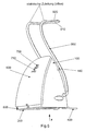
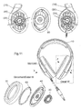
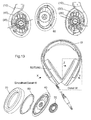
- a headphone according to a second embodiment Details of a headphone according to a second embodiment are shown. Oblique sound conversion arrangement is made possible by beveling the sound conversion arrangement.
- the headphones with the one-sided curved temple suspension and the oblique Schallwandlungsan inch allows ideal sound channeling with fewer resonances.
Landscapes
- Engineering & Computer Science (AREA)
- Power Engineering (AREA)
- Physics & Mathematics (AREA)
- Acoustics & Sound (AREA)
- Signal Processing (AREA)
- Secondary Cells (AREA)
- Charge And Discharge Circuits For Batteries Or The Like (AREA)
- Headphones And Earphones (AREA)
Description
- Die vorliegende Erfindung betrifft einen Kopfhörer mit einer einseitigen geschwungenen Bügelaufhängung sowie einer schrägen Schallanwandlungsanordhung. Die Erfindung betrifft ferner einen drahtlosen Kopfhörer sowie eine entsprechende Ladestation für den drahtlosen Kopfhörer und schließlich ein drahtloses Kopfhörersystem.
- Drahtlose Geräte wie beispielsweise drahtlose Kopfhörer weisen in der Regel einen wiederaufladbaren Akku auf. Um diesen Akku wiederaufzuladen, muss der drahtlose Kopfhörer über elektrische Kontaktflächen verfügen, welche stark oder schwach federnd ausgestaltet sein können. Stark federnde Kontakte weisen oftmals relativ lange Abmessungen auf. Bei schwach federnden Kontakten müssen die Kontakte jedoch formschlüssig zusammengebracht werden, damit der Akku entsprechend aufgeladen werden kann.
-
EP 0 389 174 offenbart einen drahtlosen Kopfhörer und eine Ladestation für einen drahtlosen Kopfhörer, die herausragende Stangen aufweist. Die Stangen werden als elektrische Zuleitung zur elektrischen Lade-Kontaktierung des drahtlosen Kopfhörers benutzt.US 5 931 683 betrifft ein Ladegerät für drahtlose Vorrichtungen. Die drahtlose Vorrichtung ist mit mindestens einem Magneten und elektrischen Ladekontakten bestückt. Bei der Aufladung des Geräts zieht der Magnet die mobilen Kontakte des Ladegeräts an. - Es ist somit Aufgabe der vorliegenden Erfindung, eine sichere elektrische Kontaktierung zum Aufladen von Akku-betriebenen Geräten vorzusehen.
- Diese Aufgabe wird durch einen drahtlosen Kopfhörer nach Anspruch 1 und eine Ladestation gemäß Anspruch 3.
- Somit wird ein drahtloser Kopfhörer mit Ladekontakten im Kopfhörerbügel und mit mindestens einem Magneten in dem Kopfhörerbügel vorgesehen. Die Erfindung betrifft ebenfalls eine Ladestation für einen entsprechenden drahtlosen Kopfhörer. Die Ladestation weist dabei Stangen als elektrische Zuleitung zur elektrischen Lade-Kontaktierung des drahtlosen Kopfhörers auf.
- Die Erfindung betrifft ebenfalls ein mobiles Endgerät mit einem wiederaufladbaren Akku, mindestens einem Ladekontakt zum Aufladen des Akkus sowie einem Magneten im Bereich der Ladekontakte. Zur Aufladung des mobilen Endgerätes wird eine Ladestation vorgesehen, welche Ladekontakte sowie Magnete im Bereich der Ladekontakte aufweist.
- Die Erfindung beruht auf dem Gedanken, eine Anziehung zweier elektrischer Kontaktflächen durch eine magnetische Anziehung zu bewirken. Hierbei kann ein Magnet auf einer oder beiden Seiten der Kontaktflächen für die nötige Anziehung sorgen.
- Somit kann eine längere Lebensdauer ermöglicht werden, da die Kontaktfedern funktionell anfälliger sind und sich leicht verbiegen können. Durch eine magnetisch verstärkte Kontaktierung lassen sich höhere konstruktive Freiheitsgrade erreichen. Ferner kann eine derartige Kontaktierung lageunabhängig erfolgen.
- In den
Figuren 1 bis 10 sind Details eines drahtlosen Kopfhörersystems mit einer Ladestation und einem drahtlosen Kopfhörer gezeigt. In denFiguren 11 bis 13 sind Details eines Kopfhörers gezeigt. -
Fig. 1 zeigt eine Draufsicht auf einen Kopfhörer gemäß dem ersten Ausführungsbeispiel. Der Kopfhörer weist dabei zwei Wandler 20, 30 sowie einen Kopfbügel 10 auf. -
Fig. 2 zeigt eine Seitenansicht eines Kopfbügels 10 vonFig. 1 . In dem Kopfbügel 10 sind Magnete M angeordnet. -
Fig. 3 zeigt eine Seitenansicht eines Kopfhörers gemäß dem ersten Ausführungsbeispiel. In dem Kopfbügel 10 sind sowohl Magnete M als auch elektrische Kontakte EK zum Aufladen des Kopfhörers angeordnet. -
Fig. 4 zeigt eine Seitenansicht eines Kopfbügels des Kopfhörers vonFig. 3 . -
Fig. 5 zeigt eine Ansicht einer Ladestation für einen drahtlosen Kopfhörer. Die Ladestation 100 ist über ein Kabel 400 mit einer Spannungsversorgung verbunden. An der Unterseite der Ladestation sind Füße 200 angeordnet. Mittels eines Ein/Ausschalters 300 lässt sich die Ladestation ein- und ausschalten. -
Fig. 6 zeigt ebenfalls eine Draufsicht auf eine Ladestation gemäß einem ersten Ausführungsbeispiel. Zusätzlich zu der Ladestation gemäßFig. 5 weist die Ladestation gemäßFig. 6 eine Stange 900 auf, welche der elektrischen Zuleitung dient. Somit weist die Stange 900, welche beispielsweise als offene elektrische Zuleitung ausgestaltet ist, einen Bereich 910 auf, welcher zur Aufnahme eines Kopfbügels eines Kopfhörers gemäß einem derFig. 1 und 2 dient. Ferner ist ein isolierter Abschnitt 920 an der Zuleitung 900 vorgesehen, um die beiden elektrischen Zuleitungen gegeneinander zu isolieren. - Um die Stabilität der Zuleitung 900 zu erhöhen, kann ein Pufferelement 140 (beispielsweise aus Gummi) zwischen der Ladestation 100 und der Zuleitung 900 angeordnet werden.
-
Fig. 7 zeigt eine weitere Seitenansicht einer Ladestation vonFig. 6 . -
Fig. 8 zeigt eine Vorderansicht einer Ladestation vonFig. 6 . Hierbei ist die Ladestation 100 sowie die Zuleitung 900 mit dem isolierten Abschnitt 920 gezeigt. -
Fig. 9 zeigt einen weiteren Kopfhörer, insbesondere einen drahtlosen Kopfhörer, welcher zusammen mit der Ladestation gemäß denFig. 6 bis 8 verwendet werden kann. -
Fig. 10 zeigt eine schematische Darstellung einer Ladestation 100 mit einem entsprechenden Kopfhörer gemäß dem ersten Ausführungsbeispiel. Der (insbesondere drahtlose) Kopfhörer weist einen Bügel 10 mit Wandlern 20, 30 auf. An der Unterseite des Bügels 10 sind zwei elektrische Kontakte EK angeordnet. Oberhalb der elektrischen Kontakte sind Magnete M angeordnet. Vorzugsweise sind die Magnete und die elektrischen Kontakte voneinander isoliert. Ferner zeigtFig. 10 eine Ladestation mit einer elektrischen Zuleitung 900. Dabei ist der Abstand zwischen den elektrischen Zuleitungen 900 und den elektrischen Kontakten EK in dem Bügel 10 des Kopfhörers derart ausgestaltet, dass wenn der Kopfhörer auf die elektrische Zuleitung gelegt wird, die elektrischen Kontakte EK mit der elektrischen Zuleitung 900 in Kontakt treten, so dass der Kopfhörer bzw. die sich darin befindlichen Akkus über die elektrische Zuleitung 900 und die elektrischen Kontakte EK aufgeladen werden kann. - Dieses drahtlose Kopfhörersystem basiert auf einem neuartigen Ladekonzept, bei dem man den Kopfbügel des Hörers einfach in die Ladevorrichtung legt. Eine Einrastung muss dabei nicht berücksichtigt werden, ebenso muss rechts oder links nicht berücksichtigt werden.
- Der drahtlose Kopfhörer zeichnet sich dadurch aus, dass die Ladekontakte EK sich in dem Kopfbügel bevorzugt in der Mitte des Kopfbügels 10 befinden. Der Kopfbügel 10 weist ferner Magnete M auf, welche sich bevorzugt in der Nähe der elektrischen Kontakte EK befinden.
- Diese Magnete bewirken hierbei einen Magnet-verstärkten Kontakt. Selbst wenn die elektrischen Kontakte in dem Kopfbügel nicht exakt auf den elektrischen Zuleitungen bzw. Stangen der Ladestation platziert werden, erfolgt eine automatische Platzierung der Kontakte durch die magnetische Anziehung der Magnete im Kopfbügel, d. h. die Stangen bzw. elektrischen Zuleitungen bestehen zumindest abschnittsweise aus magnetisierbarem Material.
- Die Ladestation 100 für den drahtlosen Kopfhörer weist zwei Stangen 900 auf, welche aus der Ladestation herausragen. Diese beiden Stangen dienen als elektrische Zuleitung für die elektrischen Kontakte EK in dem drahtlosen Kopfhörer. Demzufolge muss der Abstand zwischen den Stangen 900 an ihren freien Enden im Wesentlichen dem Abstand der elektrischen Kontakte EK in dem Kopfbügel des Kopfhörers entsprechen. Die beiden Stangen 900 können auch an ihren freien Enden miteinander verbunden werden, wenn diese Verbindung elektrisch isolierend 920 ausgelegt ist.
- Die Ladestation kann ebenfalls als Sende-/Empfangstation für den drahtlosen Kopfhörer dienen.
- Alternativ können die elektrischen Kontakte und die Magnete auch in einem Nackenbügel eines Hinterkopf-Kopfhörers angeordnet werden. Die oben beschriebenen Prinzipien der Erfindung, d. h. ein magnetisch verstärkter Ladekontakt, lassen sich ebenfalls für einen induktiven Ladevorgang einsetzen, d. h. ohne elektrischen Kontakt, wobei eine Fixierung bzw. ihre Verbesserung mittels Magneten erfolgen kann.
- Bei drahtlosen Kopfhörern mit einem wiederaufladbaren Akku erfolgt die Aufladung der Akkus in der Regel durch Absetzen des Kopfhörers und Positionieren des Kopfhörers auf eine entsprechende Ladestation. In der Regel müssen die aufzuladenden Akkus nicht entnommen werden, sondern eine elektrische Kontaktierung erfolgt über Kontakte, welche sowohl im Hörer als auch in der Ladestation angeordnet sind. Wie bereits oben beschrieben, werden häufig federnde Kontakte verwendet, um eine gute Kontaktierung zu gewährleisten. Wenn jedoch ein sicherer Kontakt über eine schwach federnde Kontaktfläche herzustellen ist, dann müssen die Kontakte formschlüssig, wie z. B. durch Führungen, zusammengebracht werden.
- Gemäß der vorliegenden Erfindung wird ein kleiner Magnet an den Kontaktflächen im Kopfhörer angeordnet, so dass der Kopfhörer sicher auf einem Ladebügel einer Ladestation aufliegt. Die Haltekraft wird dabei durch die Ausgestaltung der Magnete bestimmt. Hierbei müssen die Kontaktflächen nicht notwendigerweise federnd ausgestaltet sein.
- Alternativ zu dem oben beschriebenen Ausführungsbeispiel kann eine Magnet-verstärkte Kontaktierung dadurch erhalten werden, dass die Magnete an oder in einer Zuleitung bzw. an oder im Ladebügel der Ladestation angeordnet sind.
- Das grundlegende Konzept der Erfindung, nämlich die Magnet-verstärkte Kontaktierung von zwei elektrischen Kontakten zum Aufladen eines Akkus, lässt sich nicht nur auf drahtlose Kopfhörer mit den entsprechenden Ladestationen anwenden, sondern auch auf beliebige mobile Endgeräte und deren Ladestationen (beispielsweise Mobiltelefone, PDA, portable Audioplayer, portable Videoplayer, portable Spielekonsolen etc.), Taschenrechner, portable Diktiergeräte, Taschenlampen, Digitalkameras, welche durch wiederaufladbare Akkus mit Strom versorgt werden. Entsprechendes gilt für drahtlose Mikrofone, Taschensender, In-Ear Hörer, Hörhilfen (jeweils auch drahtlos), schnurlose Haushaltsgeräte sowie alle anderen elektrischen oder elektronischen Geräte, welche eine wiederaufladbare Energiequelle aufweisen.
- In den
Fig. 11 bis 13 sind Details eines Kopfhörers gemäß einem zweiten Ausführungsbeispiel gezeigt. Schräge Schallwandlungsanordnung wird durch Anschrägung der Schallwandlungsanordnung ermöglicht. - Der Kopfhörer mit der einseitig geschwungenen Bügelaufhängung und der schrägen Schallwandlungsanordnung ermöglicht eine ideale Schallkanalisierung mit weniger Resonanzen.
Claims (3)
- Drahtloses Kopfhörersystem, mit einem drahtlosen Kopfhörer mit einem Kopfhörerbügel, der elektrische Ladekontakte (EK) und mindestens einen Magneten (M) aufweist,
wobei die Magnete (M) und die elektrischen Ladekontakte (EK) zur Ladekontaktierung einander zugeordnet sind, und
einer Ladestation für den drahtlosen Kopfhörer mit einem Gehäuse und mindestens zwei aus dem Gehäuse herausragenden Stangen, wobei die Stangen ein erstes und zweites Ende aufweisen, wobei die ersten Enden mit dem Gehäuse gekoppelt sind und die zweiten Enden einen festen und im Wesentlichen horizontalen Abschnitt zum Aufnehmen des Kopfhörerbügels des drahtlosen Kopfhörers aufweisen, wobei die Stangen (900) als elektrische Zuleitung zur elektrischen Ladekontaktierung des drahtlosen Kopfhörers dienen, und
wobei der horizontale Abschnitt elektrische Kontakte zur elektrischen Ladekontaktierung der elektrischen Ladekontakte (EK) in dem Kopfhörerbügel aufweist. - Drahtloskopfhörersystem nach Anspruch 1, ferner mit zumindest einem Magneten in dem horizontalen Abschnitt,
- Ladestation für einen Drahtloskopfhörer mit einem Kopfhörerbügel und elektrischen Ladekontakten in dem Kopfhörerbügel, mit
einem Gehäuse und
mindestens zwei Stangen, die aus dem Gehäuse herausragen, wobei die Stangen erste und zweite Enden aufweisen,
wobei das erste Ende mit dem Gehäuse gekoppelt ist und die zweiten Enden einen festen und im Wesentlichen horizontalen Abschnitt zur Aufnahme des Kopfhörerbügels des Kopfhörers aufweisen,
wobei der horizontale Abschnitt elektrische Kontakte zur elektrischen Kontaktierung der elektrischen Ladekontakte (EK) in dem Kopfhörerbügel aufweist.
Applications Claiming Priority (2)
| Application Number | Priority Date | Filing Date | Title |
|---|---|---|---|
| DE102004001442A DE102004001442A1 (de) | 2004-01-08 | 2004-01-08 | Kopfhörer |
| PCT/EP2005/000137 WO2005067343A1 (de) | 2004-01-08 | 2005-01-10 | Kopfhörer |
Publications (2)
| Publication Number | Publication Date |
|---|---|
| EP1707028A1 EP1707028A1 (de) | 2006-10-04 |
| EP1707028B1 true EP1707028B1 (de) | 2013-03-06 |
Family
ID=34744646
Family Applications (1)
| Application Number | Title | Priority Date | Filing Date |
|---|---|---|---|
| EP05700779A Expired - Lifetime EP1707028B1 (de) | 2004-01-08 | 2005-01-10 | Kopfhörer |
Country Status (5)
| Country | Link |
|---|---|
| US (1) | US7639832B2 (de) |
| EP (1) | EP1707028B1 (de) |
| CN (1) | CN201001192Y (de) |
| DE (1) | DE102004001442A1 (de) |
| WO (1) | WO2005067343A1 (de) |
Families Citing this family (25)
| Publication number | Priority date | Publication date | Assignee | Title |
|---|---|---|---|---|
| US9526292B2 (en) | 2005-05-17 | 2016-12-27 | Michael Waters | Power modules and headgear |
| GB2441567B (en) * | 2006-09-11 | 2008-08-06 | Jye Chuang Electronic Co Ltd | Battery charger |
| US20080111304A1 (en) * | 2006-10-25 | 2008-05-15 | Chung-Hung Lin | Multimedia video and audio playing device usable with various playing appliances |
| WO2009122142A1 (en) * | 2008-04-02 | 2009-10-08 | Jason Regler | Audio or audio/visual interactive entertainment system and switching device therefor |
| ES2586621T3 (es) | 2009-02-27 | 2016-10-17 | Michael Waters | Sombrero con luz |
| DE102009030070B4 (de) * | 2009-06-22 | 2026-06-25 | Sonova Consumer Hearing Gmbh | Transport-und/oder Aufbewahrungsbehälter für aufladbare drahtlose Hörer |
| EP2309618B1 (de) * | 2009-10-08 | 2012-08-29 | Sennheiser Communications A/S | Basisstation, drahtloser Kopfhörer und Kopfbügel dafür |
| US8744098B2 (en) * | 2010-02-04 | 2014-06-03 | Apple Inc. | Using an audio cable as an inductive charging coil |
| MX2012012645A (es) | 2010-04-30 | 2013-02-26 | Michael Waters | Dispositivos de iluminacion a manos libres. |
| US20150020831A1 (en) * | 2011-12-18 | 2015-01-22 | Sis Resources Ltd. | Charging electronic cigarette |
| US9609902B2 (en) | 2011-12-23 | 2017-04-04 | Michael Waters | Headgear having a camera device |
| US9526287B2 (en) | 2011-12-23 | 2016-12-27 | Michael Waters | Lighted hat |
| US9568173B2 (en) | 2011-12-23 | 2017-02-14 | Michael Waters | Lighted hat |
| US20130238829A1 (en) * | 2012-03-08 | 2013-09-12 | Larry R. Laycock | Audio docking devices and systems |
| US10159294B2 (en) | 2012-12-19 | 2018-12-25 | Michael Waters | Lighted solar hat |
| US9717633B2 (en) * | 2013-03-15 | 2017-08-01 | Michael Waters | Lighted headgear |
| US9609423B2 (en) * | 2013-09-27 | 2017-03-28 | Volt Analytics, Llc | Noise abatement system for dental procedures |
| WO2015164287A1 (en) * | 2014-04-21 | 2015-10-29 | Uqmartyne Management Llc | Wireless earphone |
| US9742208B2 (en) | 2015-10-08 | 2017-08-22 | Headphone Events, Inc. | Electrical charging case for wireless headsets |
| KR101927245B1 (ko) * | 2018-01-12 | 2018-12-10 | (주)금오전자 | 전시용 헤드폰을 위한 충전 겸용 거치장치 |
| US20200162807A1 (en) * | 2018-11-21 | 2020-05-21 | ESI Cases & Accessories | Headphone charging apparatus |
| US10791783B1 (en) | 2019-05-16 | 2020-10-06 | Waters Industries, Inc. | Lighted headgear and accessories therefor |
| US11234068B2 (en) * | 2019-12-16 | 2022-01-25 | Gn Audio A/S | Wireless hearing device and a charging base |
| CN111864863B (zh) * | 2020-08-20 | 2025-02-25 | 厦门亿联网络技术股份有限公司 | 一种充电支架 |
| US12171293B2 (en) | 2021-12-27 | 2024-12-24 | Waters Industries, Inc. | Lighted headgear and accessories therefor |
Family Cites Families (16)
| Publication number | Priority date | Publication date | Assignee | Title |
|---|---|---|---|---|
| US3786391A (en) * | 1972-07-11 | 1974-01-15 | W Mathauser | Magnetic self-aligning electrical connector |
| DE2839148A1 (de) | 1978-09-08 | 1980-03-20 | Peter Georg Hogl | Kopfhoereraufhaengung |
| JPH0834114B2 (ja) * | 1987-04-30 | 1996-03-29 | ソニー株式会社 | コネクタ装置 |
| JP2770389B2 (ja) * | 1989-03-20 | 1998-07-02 | ソニー株式会社 | ワイヤレスヘッドホンシステム |
| JP2870791B2 (ja) * | 1989-03-20 | 1999-03-17 | ソニー株式会社 | ワイヤレスヘッドホン |
| US4930148A (en) * | 1989-10-23 | 1990-05-29 | Lee Hsiao Chung | Headband radiophone combination set |
| US5113428A (en) | 1990-09-04 | 1992-05-12 | Robert Fitzgerald | Cordless telephone headset |
| US5551065A (en) * | 1994-12-19 | 1996-08-27 | Honore; David | Wireless solar entertainment system |
| DE19546633A1 (de) * | 1995-12-14 | 1997-09-18 | Witte & Sutor Gmbh | Handleuchte |
| FR2765409A1 (fr) * | 1997-06-26 | 1998-12-31 | Philips Electronics Nv | Dispositif a contacts retractables |
| US6230029B1 (en) * | 1998-01-07 | 2001-05-08 | Advanced Mobile Solutions, Inc. | Modular wireless headset system |
| DE19802659A1 (de) * | 1998-01-24 | 1999-07-29 | Daniel Isensee | Mobiles Kopfhörer-Funktelefon mit Basis-Station |
| DE10033919A1 (de) | 2000-07-12 | 2002-02-07 | Braun Gmbh | Zahnreinigungsgerät |
| KR100395933B1 (ko) * | 2001-03-31 | 2003-09-03 | 주식회사 니오스 | 적외선 송신기 및 무선 헤드폰 |
| DE60221910T2 (de) * | 2001-06-01 | 2008-05-08 | Covidien Ag | Umlenkstück-Steckverbinder |
| JP3794363B2 (ja) * | 2002-09-13 | 2006-07-05 | ソニー株式会社 | 充電装置および充電方法 |
-
2004
- 2004-01-08 DE DE102004001442A patent/DE102004001442A1/de not_active Withdrawn
-
2005
- 2005-01-10 CN CNU2005900000218U patent/CN201001192Y/zh not_active Expired - Lifetime
- 2005-01-10 US US10/585,529 patent/US7639832B2/en not_active Expired - Fee Related
- 2005-01-10 EP EP05700779A patent/EP1707028B1/de not_active Expired - Lifetime
- 2005-01-10 WO PCT/EP2005/000137 patent/WO2005067343A1/de not_active Ceased
Also Published As
| Publication number | Publication date |
|---|---|
| US20080049963A1 (en) | 2008-02-28 |
| WO2005067343A1 (de) | 2005-07-21 |
| CN201001192Y (zh) | 2008-01-02 |
| US7639832B2 (en) | 2009-12-29 |
| DE102004001442A1 (de) | 2005-09-22 |
| EP1707028A1 (de) | 2006-10-04 |
Similar Documents
| Publication | Publication Date | Title |
|---|---|---|
| EP1707028A1 (de) | Kopfhörer | |
| DE602005002886T2 (de) | Kopfhörerantenne | |
| DE102018207922A1 (de) | Mehrteiliges, tief im Gehörgang platziertes Trommelfell-Kontakt-Hörgerät | |
| DE102009030070A1 (de) | Transport-und/oder Aufbewahrungsbehälter für aufladbare drahtlose Hörer | |
| US8496491B2 (en) | Rotated electrical connector unit | |
| DE102007042324A1 (de) | Hörgerät mit Kontaktmittel, dazugehörige externe Einheit und Batterieladeanordnung | |
| WO2004114472A1 (de) | Steckverbindung für ein mobiles endgerät | |
| DE102009033898B3 (de) | Ladegerät für ein Hörgerät mit elastischen Kontakten | |
| DE112020005574T5 (de) | Tonausgabevorrichtung | |
| CN103794902A (zh) | 具一体成型端子之电连接器 | |
| EP2091124A2 (de) | Ladegerät für eine Hörvorrichtung mit einem bewegbaren Ladekontakt und zugehöriges Hörgerätesystem | |
| AT414197B (de) | Drahtloser kopfhörer mit anschlussbuchse | |
| DE102005006404B3 (de) | Modulares Hörgerätesystem | |
| DE102007061310A1 (de) | Elektroakustischer Miniaturwandler mit Haltemittel zum Einbau in ein Hörgerät | |
| CN219041939U (zh) | 一种无线麦克风 | |
| DE102021204485A1 (de) | Ladegerät eines Hörgeräts | |
| EP4456565A1 (de) | Hörinstrument und zugehöriges binaurales hörsystem | |
| CN203800220U (zh) | 具一体成型端子之电连接器 | |
| EP2026602A1 (de) | Hörvorrichtung mit beweglichem Ladekontakt | |
| EP2592849A2 (de) | Hörvorrichtung mit einem Batteriefach | |
| EP4387272B1 (de) | Ladekontaktanschluss | |
| CN217770315U (zh) | 一种具有极性转换的耳机插头装置 | |
| EP4425665A2 (de) | Hörinstrument | |
| EP1414272B1 (de) | Hörgerät mit einer externen Elektronikkomponente | |
| EP4250771B1 (de) | Hörgerät |
Legal Events
| Date | Code | Title | Description |
|---|---|---|---|
| PUAI | Public reference made under article 153(3) epc to a published international application that has entered the european phase |
Free format text: ORIGINAL CODE: 0009012 |
|
| 17P | Request for examination filed |
Effective date: 20060808 |
|
| AK | Designated contracting states |
Kind code of ref document: A1 Designated state(s): DE ES FR GB NL |
|
| DAX | Request for extension of the european patent (deleted) | ||
| RBV | Designated contracting states (corrected) |
Designated state(s): DE ES FR GB NL |
|
| 17Q | First examination report despatched |
Effective date: 20080915 |
|
| REG | Reference to a national code |
Ref country code: DE Ref legal event code: R079 Ref document number: 502005013518 Country of ref document: DE Free format text: PREVIOUS MAIN CLASS: H04R0005033000 Ipc: H04R0001100000 |
|
| RIC1 | Information provided on ipc code assigned before grant |
Ipc: H04R 1/10 20060101AFI20120613BHEP |
|
| GRAP | Despatch of communication of intention to grant a patent |
Free format text: ORIGINAL CODE: EPIDOSNIGR1 |
|
| GRAS | Grant fee paid |
Free format text: ORIGINAL CODE: EPIDOSNIGR3 |
|
| GRAA | (expected) grant |
Free format text: ORIGINAL CODE: 0009210 |
|
| AK | Designated contracting states |
Kind code of ref document: B1 Designated state(s): DE ES FR GB NL |
|
| REG | Reference to a national code |
Ref country code: GB Ref legal event code: FG4D Free format text: NOT ENGLISH |
|
| REG | Reference to a national code |
Ref country code: DE Ref legal event code: R096 Ref document number: 502005013518 Country of ref document: DE Effective date: 20130502 |
|
| PG25 | Lapsed in a contracting state [announced via postgrant information from national office to epo] |
Ref country code: ES Free format text: LAPSE BECAUSE OF FAILURE TO SUBMIT A TRANSLATION OF THE DESCRIPTION OR TO PAY THE FEE WITHIN THE PRESCRIBED TIME-LIMIT Effective date: 20130617 |
|
| REG | Reference to a national code |
Ref country code: NL Ref legal event code: VDEP Effective date: 20130306 |
|
| PG25 | Lapsed in a contracting state [announced via postgrant information from national office to epo] |
Ref country code: NL Free format text: LAPSE BECAUSE OF FAILURE TO SUBMIT A TRANSLATION OF THE DESCRIPTION OR TO PAY THE FEE WITHIN THE PRESCRIBED TIME-LIMIT Effective date: 20130306 |
|
| PLBE | No opposition filed within time limit |
Free format text: ORIGINAL CODE: 0009261 |
|
| STAA | Information on the status of an ep patent application or granted ep patent |
Free format text: STATUS: NO OPPOSITION FILED WITHIN TIME LIMIT |
|
| 26N | No opposition filed |
Effective date: 20131209 |
|
| REG | Reference to a national code |
Ref country code: DE Ref legal event code: R097 Ref document number: 502005013518 Country of ref document: DE Effective date: 20131209 |
|
| REG | Reference to a national code |
Ref country code: FR Ref legal event code: PLFP Year of fee payment: 12 |
|
| REG | Reference to a national code |
Ref country code: FR Ref legal event code: PLFP Year of fee payment: 13 |
|
| PGFP | Annual fee paid to national office [announced via postgrant information from national office to epo] |
Ref country code: FR Payment date: 20170124 Year of fee payment: 13 |
|
| PGFP | Annual fee paid to national office [announced via postgrant information from national office to epo] |
Ref country code: GB Payment date: 20170125 Year of fee payment: 13 |
|
| GBPC | Gb: european patent ceased through non-payment of renewal fee |
Effective date: 20180110 |
|
| PG25 | Lapsed in a contracting state [announced via postgrant information from national office to epo] |
Ref country code: FR Free format text: LAPSE BECAUSE OF NON-PAYMENT OF DUE FEES Effective date: 20180131 |
|
| REG | Reference to a national code |
Ref country code: FR Ref legal event code: ST Effective date: 20180928 |
|
| PG25 | Lapsed in a contracting state [announced via postgrant information from national office to epo] |
Ref country code: GB Free format text: LAPSE BECAUSE OF NON-PAYMENT OF DUE FEES Effective date: 20180110 |
|
| REG | Reference to a national code |
Ref country code: DE Ref legal event code: R081 Ref document number: 502005013518 Country of ref document: DE Owner name: SENNHEISER CONSUMER AUDIO GMBH, DE Free format text: FORMER OWNER: SENNHEISER ELECTRONIC GMBH & CO. KG, 30900 WEDEMARK, DE |
|
| P01 | Opt-out of the competence of the unified patent court (upc) registered |
Effective date: 20230612 |
|
| PGFP | Annual fee paid to national office [announced via postgrant information from national office to epo] |
Ref country code: DE Payment date: 20240129 Year of fee payment: 20 |
|
| REG | Reference to a national code |
Ref country code: DE Ref legal event code: R071 Ref document number: 502005013518 Country of ref document: DE |