EP1706558B1 - Collapsible vehicle cover - Google Patents
Collapsible vehicle cover Download PDFInfo
- Publication number
- EP1706558B1 EP1706558B1 EP05702646A EP05702646A EP1706558B1 EP 1706558 B1 EP1706558 B1 EP 1706558B1 EP 05702646 A EP05702646 A EP 05702646A EP 05702646 A EP05702646 A EP 05702646A EP 1706558 B1 EP1706558 B1 EP 1706558B1
- Authority
- EP
- European Patent Office
- Prior art keywords
- hoop
- vehicle cover
- portable vehicle
- members
- cover
- Prior art date
- Legal status (The legal status is an assumption and is not a legal conclusion. Google has not performed a legal analysis and makes no representation as to the accuracy of the status listed.)
- Not-in-force
Links
Images

Classifications
-
- E—FIXED CONSTRUCTIONS
- E04—BUILDING
- E04H—BUILDINGS OR LIKE STRUCTURES FOR PARTICULAR PURPOSES; SWIMMING OR SPLASH BATHS OR POOLS; MASTS; FENCING; TENTS OR CANOPIES, IN GENERAL
- E04H6/00—Buildings for parking cars, rolling-stock, aircraft, vessels or like vehicles, e.g. garages
- E04H6/02—Small garages, e.g. for one or two cars
- E04H6/04—Small garages, e.g. for one or two cars wheeled, hinged, foldable, telescopic, swinging or otherwise movable
-
- E—FIXED CONSTRUCTIONS
- E04—BUILDING
- E04H—BUILDINGS OR LIKE STRUCTURES FOR PARTICULAR PURPOSES; SWIMMING OR SPLASH BATHS OR POOLS; MASTS; FENCING; TENTS OR CANOPIES, IN GENERAL
- E04H15/00—Tents or canopies, in general
- E04H15/32—Parts, components, construction details, accessories, interior equipment, specially adapted for tents, e.g. guy-line equipment, skirts, thresholds
- E04H15/34—Supporting means, e.g. frames
- E04H15/36—Supporting means, e.g. frames arch-shaped type
- E04H15/40—Supporting means, e.g. frames arch-shaped type flexible
Definitions
- the present invention relates to vehicle covers and in particular to vehicle covers that are collapsible and separable for transport.
- the invention has been developed primarily as a collapsible vehicle cover for an automobile and will be described hereafter with reference to this application. However, it will be appreciated that the invention is not limited to this particular field of use.
- Portable covers for vehicles are known.
- they comprise four stand members and rigid or flexible covers connectable with the stand members.
- the stand members are usually either secured to the ground or to the vehicle.
- Other known portable vehicle covers include a base and a plurality of hoop members engageable with the base.
- a flexible cover is disposed above, and is secured to the hoop members to form a substantially enclosed structure.
- a portable cover of this type is disclosed in US Patent No. 4,886,083 (GAMACHE ). Described, is a portable cover including a frame and a weather resistant flexible sheet attached thereto.
- the frame includes a plurality of hingedly connected transversely extending hoops arranged such that they support the flexible sheet over the base to form the vehicle cover.
- the cover is secured by driving the vehicle up onto wheel pads included as part of the base.
- a disadvantage of this portable vehicle cover is that it is not collapsible enough for easy transport in a kit form.
- a portable vehicle cover including:
- the hoop members are substantially resilient such that they form substantially arcuate hoops when connected to the frame.
- Each hoop member is preferably formed from two or more releasably connectable pieces. Alternatively, each hoop member may be formed from a single continuous piece.
- One or more of the hoop members are preferably adapted to be hingedly connected to the base frame and more preferably two end hoop members are hingedly connected to the base frame.
- the flexible cover include a hoop engaging sleeve at each of its ends adapted to slidably engage with the end hoop members.
- the flexible cover is secured in an extended configuration by selectively affixing to the base frame utilising a plurality of flexible strap members having selectively adjustable lengths.
- the base frame includes two transversely spaced longitudinally extending elongate frame members. It is preferred that each elongate frame member is formed from two hingedly connected elongate portions. Preferably, each elongate frame member includes one or more, and desirably two, telescopingly connected extensions for selectively extending the length of the base frame.
- the portable vehicle cover includes one or more transversely extending flexible and selectively extendible tie members, for spacing apart the elongate frame members. It is preferred that these tie members take the form of flexible straps.
- the base frame includes four tyre pads for retaining the portable vehicle cover with respect to the vehicle. It is preferred that at least two of the tyre pads include two hingedly connected length adjustment portions. Desirably, at least two of the tyre pads are hingedly connected to the base.
- the base frame includes a plurality of hoop engaging sockets. It is preferred that four of the hoop engaging sockets are hingedly connected to the elongate frame members. It is further preferred that the hoop engaging sockets are angled outwardly away from the portable vehicle cover. It is desired that these sockets are inclined at an angle of between 10 and 20 degrees to the vertical plane. Preferably, releasable fasteners are used to retain one end of each hoop members in the hoop engaging sockets.
- the portable vehicle cover includes a hoop clamp for releasably clamping at least two hoop members.
- the hoop clamp is preferably permanently affixed to one hoop member.
- the hoop clamp is in the form of a hub for receiving one or more ends of the releasably connectable hoop member pieces.
- the portable vehicle cover includes a centrally extending hoop member, two diagonally extending hoop members and two pivotally connected end hoop members.
- the centrally extending hoop member includes at least two pivotally connected extension arms for supporting said portable vehicle against the vehicle.
- each extension arm has a selectively extendable length. It is further preferred that each extension arm has a suction cap at it distal end, the suction cap being engagable with the vehicle.
- each hoop member is formed from a substantially resilient material such as fibreglass or suitable plastic.
- each elongate frame member is substantially formed from a tubular material and desirably formed from tubular aluminium.
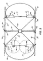
- the portable vehicle cover 10 includes a base frame 12 and five transversely extending hoop members 14. Each hoop member is releasably connectable with the base frame such that two hoop members extend diagonally across the frame in a cruciform orientation.
- the portable vehicle cover further includes a flexible cover 16, which engages with the hoop members to form a weather shield for a vehicle 18.
- the transversely extending hoop members 14 include a central 20, two diagonal 22 and two end hoop members 24.
- Each hoop member is constructed from a substantially resilient material, such as fibreglass or suitable plastic such that arcuate hoops are formed when they are connected to the base frame.
- each hoop member is formed from two or more releasably connectable pieces to facilitate transport in a kit.
- the hoop members are formed from a single continuous piece.
- the two end hoop members 24 are hingedly connected to the base frame to allow vehicle access when assembled.
- a hoop clamp 56 releasably clamps together the diagonally and central hoop members 22, 20 at their centres.
- the hoop clamp is permanently fixed to the central hoop member 20.
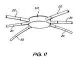
- the central and diagonal hoop members are discontinuous and the hoop clamp is in the form of a centrally disposed hub 57.
- the diagonal and central hoop members 22 and 20 each have one-half end releasably connected to the hub.
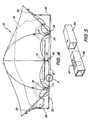
- the flexible cover 16 is formed a flexible material having favourable weather resistant properties.
- a securing means in the form of a hoop-receiving sleeve 26 is disposed at each end of the flexible cover.
- the hoop-receiving sleeve slidably receives the end hoop members 24 such that the flexible cover is secured in an extended configuration by selectively affixing to the base frame 12 using straps 28.
- a plurality of flexible strap members 30, each having selectively adjustable lengths, is disposed about the base frame 12 and is used to retain the flexible cover to the base frame.
- the strap members are connectable with respective connecting points 31 on the flexible cover.
- Base frame 12 includes two transversely spaced and longitudinally extending elongate frame members 32. Each frame member is formed from two elongate portions 34 hingedly connected at hinge joint 36. A pair of telescopically connected extensions 38 is disposed at each end of the frame members for selectively extending the length of the base frame. As best shown in Figure 5 , the extensions 38 are retained in their extended states using ball catch joints 40. In an alternative not shown embodiment, the extensions 38 may be retained using other suitable securing means.
- the frame members 32 be generally formed from aluminium or plastic tubes so as to facilitate their telescopic construction and easy manoeuvrability,
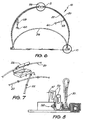
- the base frame 12 further includes ten hoop engaging sockets 50 for retaining the ends of each hoop member 14 ( Figure 3 ).
- Four of the hoop engaging sockets are hingedly connected to the ends of the telescopic extensions 38 at hinge joints 52.
- the hoop engaging sockets are inclined outwardly at an angle of approximately 10° to the vertical plane so as to create the arcuate shape of the assembled vehicle cover 10.
- Base frame 12 additionally includes four tyre pads 42 for retaining the portable vehicle cover 10 with respect to the vehicle 18.
- the tyre pads extend laterally from the frame members 32 at a location substantially adjacent to the diagonal hoop engaging sockets.
- Two of the tyre pads 42' include a hingedly connected length-adjusting portion 44 for accommodating vehicles with different wheelbases.
- tyre pads 42' are hingedly connected to the base frame to perform the same function.
- Two transversely extending tie members in the form of flexible straps 46, retain the frame members 32 in a fixed spaced apart relationship against the lateral force applied by the resilient hoop members.
- the flexible straps are releasably connected to the tyre pads or alternatively directly to the frame members (not shown), using hook connectors 48
- a pair of support arms 58 are pivotally connected to the central hoop member 20, and are used to space the central hoop member 20 away from, and support the vehicle cover 10 against, the vehicle 18.
- Each support arm is selectively adjustable in length and has a window engaging suction cap 60 disposed at its distal end.
- the portable vehicle cover 10 is transported in a kit bag and therefore first requires assembly before use.
- the kit is assembled with reference to Figures 1 to 11 , using the following method:
- the two frame members 32 are laid down on a ground surface such that they are correctly spaced to suit the vehicle.
- Each of the telescoping extensions 38 can then be extended until the ball catch joints 40 snapingly lock them into their extended configuration.
- the hoop engaging sockets 50 are then ready to receive the ends of each hoop member 14,
- the two hingedly connected length-adjusting portions 44 of two tyre pads 42' should then be rotated into the required position to suit the vehicle's wheelbase.
- the flexible straps 46 are then connected to the tyre pads and locked into position such to retain the transverse distance between the two frame members 32.
- the diagonal hoop members 22 and the central hoop member 20 can be installed in position by inserting their ends into respective sockets and securing using holding pins 54 (if so required). Hoop clamp 56 is then used to retain these three hoop members together.
- the hoop clamp is in the form of a hub 57
- the diagonal and central hoop members are simply assembled around the hub and then inserted into their respective sockets.
- one end hoop member 24 is inserted into one of the hoop-receiving sleeves 26. This end hoop member is then inserted in one of the end hinged hoop engaging sockets 50. With the end hoop engaging socket rotated at an angle of approximately 90° to the horizontal, the other end of the end hoop member 24 is then bent over and inserted and secured in the transversely opposite hoop engaging socket. The process is then repeated for the other end hoop member, thereby extending the flexible cover.
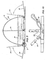
- the flexible cover 16 can now be pulled over the assembled central and diagonal hoop members 20 and 22 to the other side of the base frame 12.
- the flexible cover is secured to the base frame using the plurality of flexible strap members 46.
- One end hoop member is then rotated upwardly to 90° so that the vehicle 18 can be driven into the assembled vehicle cover 10 up until the driver's door aligns with pre-marked indicia (not shown) on both sides of the flexible cover 16.
- the vehicle tyres will be resting on the four tyre pads 42 and the portable vehicle cover should be sufficiently secured to the ground using the vehicle weight.
- the two pivotally connected extension arms 58 are positioned such that the suction cups 60 project onto, and engage with, the vehicle's driver's and front passenger's windows, thereby substantially restraining the assembled vehicle cover 10 against side loads.
- the illustrated portable vehicle cover provides a vehicle cover that is easy to assemble and cheap to manufacture.
- the illustrated portable vehicle is easily transportable in a kit form.
- hoop members 14 may be eight hoop members 14 to accommodate a vehicle of longer length, such as a small truck or SUV.
- a vehicle of longer length such as a small truck or SUV.
- the portable vehicle cover 10 may employ containers, secured to the frame, that hold water, sand or other suitable material to further secure the cover against extreme wind loads.
Abstract
Description
- The present invention relates to vehicle covers and in particular to vehicle covers that are collapsible and separable for transport.
- The invention has been developed primarily as a collapsible vehicle cover for an automobile and will be described hereafter with reference to this application. However, it will be appreciated that the invention is not limited to this particular field of use.
- Any discussion of the prior art throughout the specification should in no way be considered as an admission that such prior art is widely known or forms part of common general knowledge in the field.
- Portable covers for vehicles are known. In one form, they comprise four stand members and rigid or flexible covers connectable with the stand members. The stand members are usually either secured to the ground or to the vehicle.
- Other known portable vehicle covers include a base and a plurality of hoop members engageable with the base. A flexible cover is disposed above, and is secured to the hoop members to form a substantially enclosed structure.
- One known portable vehicle cover of this type is disclosed in
US Patent No. 4,886,083 (GAMACHE ). Described, is a portable cover including a frame and a weather resistant flexible sheet attached thereto. The frame includes a plurality of hingedly connected transversely extending hoops arranged such that they support the flexible sheet over the base to form the vehicle cover. The cover is secured by driving the vehicle up onto wheel pads included as part of the base. A disadvantage of this portable vehicle cover is that it is not collapsible enough for easy transport in a kit form. - It is an object of the invention to overcome or ameliorate at least one of the disadvantages of the prior art, or to provide a useful alternative.
- Moreover, it is an object of the invention in its preferred form to provide a portable vehicle cover that is easily collapsible, simple to erect and cheap to manufacture.
- According to the invention there is provided a portable vehicle cover including:
- a base frame;
- a plurality of transversely extending hoop members, each hoop member adapted to be releasably connectable with the frame such that at least two of the hoop members substantially extend diagonally across the frame in a cruciform orientation; and
- a flexible cover engagable with the hoop members to form a weather shield for a vehicle.
- It is preferred that the hoop members are substantially resilient such that they form substantially arcuate hoops when connected to the frame. Each hoop member is preferably formed from two or more releasably connectable pieces. Alternatively, each hoop member may be formed from a single continuous piece. One or more of the hoop members are preferably adapted to be hingedly connected to the base frame and more preferably two end hoop members are hingedly connected to the base frame.
- Preferably, the flexible cover include a hoop engaging sleeve at each of its ends adapted to slidably engage with the end hoop members.
- Preferably, the flexible cover is secured in an extended configuration by selectively affixing to the base frame utilising a plurality of flexible strap members having selectively adjustable lengths.
- In a preferred form, the base frame includes two transversely spaced longitudinally extending elongate frame members. It is preferred that each elongate frame member is formed from two hingedly connected elongate portions. Preferably, each elongate frame member includes one or more, and desirably two, telescopingly connected extensions for selectively extending the length of the base frame.
- Preferably, the portable vehicle cover includes one or more transversely extending flexible and selectively extendible tie members, for spacing apart the elongate frame members. It is preferred that these tie members take the form of flexible straps.
- Preferably, the base frame includes four tyre pads for retaining the portable vehicle cover with respect to the vehicle. It is preferred that at least two of the tyre pads include two hingedly connected length adjustment portions. Desirably, at least two of the tyre pads are hingedly connected to the base.
- Preferably, the base frame includes a plurality of hoop engaging sockets. It is preferred that four of the hoop engaging sockets are hingedly connected to the elongate frame members. It is further preferred that the hoop engaging sockets are angled outwardly away from the portable vehicle cover. It is desired that these sockets are inclined at an angle of between 10 and 20 degrees to the vertical plane. Preferably, releasable fasteners are used to retain one end of each hoop members in the hoop engaging sockets.
- Preferably, the portable vehicle cover includes a hoop clamp for releasably clamping at least two hoop members. The hoop clamp is preferably permanently affixed to one hoop member. Preferably, the hoop clamp is in the form of a hub for receiving one or more ends of the releasably connectable hoop member pieces.
- In a preferred form the portable vehicle cover includes a centrally extending hoop member, two diagonally extending hoop members and two pivotally connected end hoop members. Preferably, the centrally extending hoop member includes at least two pivotally connected extension arms for supporting said portable vehicle against the vehicle. Preferably, each extension arm has a selectively extendable length. It is further preferred that each extension arm has a suction cap at it distal end, the suction cap being engagable with the vehicle.
- Preferably, each hoop member is formed from a substantially resilient material such as fibreglass or suitable plastic.
- Preferably each elongate frame member is substantially formed from a tubular material and desirably formed from tubular aluminium.
- A preferred embodiment of the invention will now be described, by way of example only, with reference to the accompanying drawings in which:
-
Figure 1 is a front view of a portable vehicle cover according to the invention, shown fully assembled and with a vehicle inside; -
Figure 2 is an end view of the portable vehicle cover ofFigure 1 ; -
Figure 3 is a plan view of a portable vehicle cover according to the invention, shown partly assembled; -
Figure 4 is a side view of the portable vehicle cover ofFigure 1 ; -
Figure 5 is an enlarged perspective view of area A ofFigure 4 ; -
Figure 6 is an end view of the portable vehicle cover ofFigure 3 ; -
Figure 7 is an enlarged exploded view of area B ofFigure 6 ; -
Figure 8 is an enlarged view of area C ofFigure 6 ; -
Figure 9 is side view of a portable vehicle cover according to the invention, shown partly assembled; and -
Figure 10 is an enlarged view of area D ofFigure 9 . -
Figure 11 is an enlarged perspective cut away view of a hub according to an alternate embodiment of the invention. - Referring to the accompanying drawings, the
portable vehicle cover 10 includes abase frame 12 and five transversely extendinghoop members 14. Each hoop member is releasably connectable with the base frame such that two hoop members extend diagonally across the frame in a cruciform orientation. The portable vehicle cover further includes aflexible cover 16, which engages with the hoop members to form a weather shield for avehicle 18. - As best shown on
Figure 3 , the transversely extendinghoop members 14 include a central 20, two diagonal 22 and twoend hoop members 24. Each hoop member is constructed from a substantially resilient material, such as fibreglass or suitable plastic such that arcuate hoops are formed when they are connected to the base frame. - In the illustrated embodiment, each hoop member is formed from two or more releasably connectable pieces to facilitate transport in a kit. Alternatively, in another not shown embodiment, the hoop members are formed from a single continuous piece. The two
end hoop members 24 are hingedly connected to the base frame to allow vehicle access when assembled. - Referring now to
Figures 6 and 7 , ahoop clamp 56 releasably clamps together the diagonally andcentral hoop members central hoop member 20. - In an alternate embodiment shown in
Figure 11 , the central and diagonal hoop members are discontinuous and the hoop clamp is in the form of a centrally disposedhub 57. In this case, the diagonal andcentral hoop members - Referring to
Figure 4 , theflexible cover 16 is formed a flexible material having favourable weather resistant properties. A securing means in the form of a hoop-receivingsleeve 26 is disposed at each end of the flexible cover. The hoop-receiving sleeve slidably receives theend hoop members 24 such that the flexible cover is secured in an extended configuration by selectively affixing to thebase frame 12 using straps 28. - A plurality of
flexible strap members 30, each having selectively adjustable lengths, is disposed about thebase frame 12 and is used to retain the flexible cover to the base frame. The strap members are connectable with respective connectingpoints 31 on the flexible cover. -
Base frame 12 includes two transversely spaced and longitudinally extendingelongate frame members 32. Each frame member is formed from twoelongate portions 34 hingedly connected at hinge joint 36. A pair of telescopically connectedextensions 38 is disposed at each end of the frame members for selectively extending the length of the base frame. As best shown inFigure 5 , theextensions 38 are retained in their extended states using ball catch joints 40. In an alternative not shown embodiment, theextensions 38 may be retained using other suitable securing means. - It is proposed that the
frame members 32 be generally formed from aluminium or plastic tubes so as to facilitate their telescopic construction and easy manoeuvrability, - The
base frame 12 further includes tenhoop engaging sockets 50 for retaining the ends of each hoop member 14 (Figure 3 ). Four of the hoop engaging sockets are hingedly connected to the ends of thetelescopic extensions 38 at hinge joints 52. As best shown onFigure 8 , the hoop engaging sockets are inclined outwardly at an angle of approximately 10° to the vertical plane so as to create the arcuate shape of the assembledvehicle cover 10. - It will be appreciated that, due to the outward inclination of each hoop engaging socket and the lateral force applied on each socket by engagement with each resilient hoop member, frictional forces are advantageously used to retain hoop members ends in the sockets. However, in the case where additional security is required, a releasable fastening means such as releasable holding pins 54 is used (
Figure 10 ). -
Base frame 12 additionally includes fourtyre pads 42 for retaining theportable vehicle cover 10 with respect to thevehicle 18. In the illustrated embodiment shown onFigure 3 , the tyre pads extend laterally from theframe members 32 at a location substantially adjacent to the diagonal hoop engaging sockets. Two of the tyre pads 42' include a hingedly connected length-adjustingportion 44 for accommodating vehicles with different wheelbases. Alternatively, tyre pads 42' are hingedly connected to the base frame to perform the same function. - Two transversely extending tie members, in the form of
flexible straps 46, retain theframe members 32 in a fixed spaced apart relationship against the lateral force applied by the resilient hoop members. The flexible straps are releasably connected to the tyre pads or alternatively directly to the frame members (not shown), usinghook connectors 48 - Referring now to
Figures 1 and6 , a pair ofsupport arms 58 are pivotally connected to thecentral hoop member 20, and are used to space thecentral hoop member 20 away from, and support thevehicle cover 10 against, thevehicle 18. Each support arm is selectively adjustable in length and has a window engagingsuction cap 60 disposed at its distal end. - In use, the
portable vehicle cover 10 is transported in a kit bag and therefore first requires assembly before use. The kit is assembled with reference toFigures 1 to 11 , using the following method: - The two
frame members 32 are laid down on a ground surface such that they are correctly spaced to suit the vehicle. Each of thetelescoping extensions 38 can then be extended until theball catch joints 40 snapingly lock them into their extended configuration. Thehoop engaging sockets 50 are then ready to receive the ends of eachhoop member 14, - The two hingedly connected length-adjusting
portions 44 of two tyre pads 42' should then be rotated into the required position to suit the vehicle's wheelbase. The flexible straps 46 are then connected to the tyre pads and locked into position such to retain the transverse distance between the twoframe members 32. - After assembling each
hoop member 14 to its full length, thediagonal hoop members 22 and thecentral hoop member 20 can be installed in position by inserting their ends into respective sockets and securing using holding pins 54 (if so required).Hoop clamp 56 is then used to retain these three hoop members together. In the alternate embodiment shown inFigure 11 where the hoop clamp is in the form of ahub 57, the diagonal and central hoop members are simply assembled around the hub and then inserted into their respective sockets. - After unrolling the flexible cover 16 (as it was stored in the kit), one
end hoop member 24 is inserted into one of the hoop-receivingsleeves 26. This end hoop member is then inserted in one of the end hingedhoop engaging sockets 50. With the end hoop engaging socket rotated at an angle of approximately 90° to the horizontal, the other end of theend hoop member 24 is then bent over and inserted and secured in the transversely opposite hoop engaging socket. The process is then repeated for the other end hoop member, thereby extending the flexible cover. - As shown in
Figure 9 , theflexible cover 16 can now be pulled over the assembled central anddiagonal hoop members base frame 12. When this is completed, the flexible cover is secured to the base frame using the plurality offlexible strap members 46. - One end hoop member is then rotated upwardly to 90° so that the
vehicle 18 can be driven into the assembledvehicle cover 10 up until the driver's door aligns with pre-marked indicia (not shown) on both sides of theflexible cover 16. At this stage, the vehicle tyres will be resting on the fourtyre pads 42 and the portable vehicle cover should be sufficiently secured to the ground using the vehicle weight. - Once the driver exists the vehicle, the two pivotally connected
extension arms 58 are positioned such that thesuction cups 60 project onto, and engage with, the vehicle's driver's and front passenger's windows, thereby substantially restraining the assembledvehicle cover 10 against side loads. - As best shown in
Figure 4 , the twoend hoop members 24 are now both rotated downwardly, to approximately 45° to the vertical plane, and secured to each end of the elongate frame members using straps 28. Thus, the assembly process is completed andportable vehicle cover 10 is positively secured to thevehicle 18. - It will be appreciated that the illustrated portable vehicle cover provides a vehicle cover that is easy to assemble and cheap to manufacture. Advantageously, the illustrated portable vehicle is easily transportable in a kit form.
- Although the invention has been described with reference to a specific example, it will be appreciated by those skilled in the art that the invention may be embodied in many other forms.
- For example, in one alternate form there may be eight
hoop members 14 to accommodate a vehicle of longer length, such as a small truck or SUV. In an alternate form, there may only be three hoop members required to accommodate a smaller vehicle. - It should be understood that the
portable vehicle cover 10 may employ containers, secured to the frame, that hold water, sand or other suitable material to further secure the cover against extreme wind loads.
Claims (30)
- A portable vehicle cover (10) including:a base frame (12);a plurality oftransversely extending hoop members (14); anda flexible cover (16) engagable with said hoop members to form a weather shield for a vehicle,characterised in thateach hoop member (14) is adapted to be releasably connectable with said base frame (12) and at least two of said hoop members (14) substantially extend diagonally across said base frame (12) in a cruciform orientation.
- A portable vehicle cover (10) according to claim 1, wherein said hoop members (14) are substantially resilient such that they form substantially arcuate hoops when connected to said frame.
- A portable vehicle cover (10) according to claim 1 or claim 2, wherein each hoop member (14) is formed from two or more releasably connectable pieces.
- A portable vehicle cover (10) according to claim 1 or claim 2, wherein each hoop member (14) is formed from a single continuous piece.
- A portable vehicle cover (10) according to any one of the preceding claims, wherein one or more of said hoop members (14) are adapted to be hingedly connected to said base frame (12).
- A portable vehicle cover (10) according to any one of the preceding claims, including a plurality of end hoop members (24), said end hoop members being hingedly connected to said base frame (12).
- A portable vehicle cover (10) according to claim 6, wherein said flexible cover (16) includes a hoop engaging sleeve (26) at each of its ends for slidably engaging with said end hoop members (24).
- A portable vehicle cover (10) according to any one of the preceding claims, wherein said flexible cover (16) is secured to said base frame utilising a plurality of flexible strap members (30) having selectively adjustable lengths.
- A portable vehicle cover (10) according to any one of the preceding claims, wherein said base frame (12) includes two transversely spaced longitudinally extending elongate frame members (32).
- A portable vehicle cover (10) according to claim 9, wherein each elongate frame member (32) is formed from two hingedly connected elongate portions (34).
- A portable vehicle cover (10) according to claim 9 or claim 10, wherein each elongate frame member (32) includes one or more telescopingly connected extensions (38) for selectively extending the length of said base frame.
- A portable vehicle cover (10) according to claim 11, wherein each elongate frame member (32) includes two telescopingly connected extensions (38).
- A portable vehicle cover (10) according to any one of claims 9 to 12, including one or more transversely extending, flexible and selectively extendible tie members for spacing apart said elongate frame members (32).
- A portable vehicle cover (10) according to claim 13, wherein said tie members are flexible straps (46).
- A portable vehicle cover (10) according to any one of the preceding claims, wherein said base frame (12) includes four tyre pads (42) for retaining said portable vehicle cover (10) with respect to the vehicle to be covered.
- A portable vehicle cover (10) according to claim 15, wherein at least two of said tyre pads (42) include two hingedly connected length adjustment portions (44).
- A portable vehicle cover (10) according to claim 15 or claim 16, wherein at least two of said tyre pads (42) are hingedly connected to the base frame (12).
- A portable vehicle cover (10) according to any one of claims 9 to 17, wherein said base frame (12) includes a plurality of hoop engaging sockets (50).
- A portable vehicle cover (10) according to claim 18, wherein four of said hoop-engaging sockets (50) are hingedly connected to said elongate frame members (32).
- A portable vehicle cover (10) according to claim 18 or claim 19, wherein said hoop engaging sockets (50) are angled outwardly away from said portable vehicle cover (10).
- A portable vehicle cover (10) according to claim 20, wherein said sockets (50) are inclined at an angle of between 10 and 20 degrees to the vertical plane.
- A portable vehicle cover (10) according to any one of claims 18 to 21, wherein each hoop engaging socket (50) includes a releasable fastener for retaining the end of each hoop member (14).
- A portable vehicle cover (10) according to any one claims 1 to 3 or claims 5 to 22, wherein said portable vehicle cover includes a hoop clamp (56) for releasably clamping at least two hoop members (14).
- A portable vehicle cover (10) according to claim 23, wherein each hoop member (14) is formed from two or more releasably connectable pieces and wherein said hoop clamp (56) is in the form of a hub (57) for receiving one or more ends of said releasably connectable hoop member pieces.
- A portable vehicle cover (10) according to any one of the preceding claims including a centrally extending hoop member (20), two diagonally extending hoop members (22) and two pivotally connected end hoop members (24).
- A portable vehicle cover (10) according to claim 25, wherein said centrally extending hoop member (20) includes one or more pivotally connected extension arms (58) for supporting said portable vehicle cover against the vehicle to be covered.
- A portable vehicle cover (10) according to claim 26, wherein said extension arm (58) has a selectively extendable length.
- A portable vehicle cover (10) according to claim 26 or claim 27, wherein said extension arm (58) has a suction cap (60) at it distal end for engaging the vehicle to be covered.
- A portable vehicle cover (10) according to any one of the preceding claims, wherein said hoop members (14) are formed from a substantially resilient material such as fibreglass or suitable plastic.
- A portable vehicle cover (10) according to any one of claims 9 to 29, wherein each elongate frame member (32) is substantially formed from tubular aluminium.
Applications Claiming Priority (3)
| Application Number | Priority Date | Filing Date | Title |
|---|---|---|---|
| AU2004900130A AU2004900130A0 (en) | 2004-01-12 | Compact Collapsible Carport | |
| AU2004903596A AU2004903596A0 (en) | 2004-06-30 | Collapsible vehicle cover | |
| PCT/IB2005/050128 WO2005068752A1 (en) | 2004-01-12 | 2005-01-12 | Collapsible vehicle cover |
Publications (3)
| Publication Number | Publication Date |
|---|---|
| EP1706558A1 EP1706558A1 (en) | 2006-10-04 |
| EP1706558A4 EP1706558A4 (en) | 2008-04-23 |
| EP1706558B1 true EP1706558B1 (en) | 2011-06-15 |
Family
ID=34795981
Family Applications (1)
| Application Number | Title | Priority Date | Filing Date |
|---|---|---|---|
| EP05702646A Not-in-force EP1706558B1 (en) | 2004-01-12 | 2005-01-12 | Collapsible vehicle cover |
Country Status (8)
| Country | Link |
|---|---|
| US (1) | US7604016B2 (en) |
| EP (1) | EP1706558B1 (en) |
| JP (1) | JP2007518902A (en) |
| CN (1) | CN1910329B (en) |
| AT (1) | ATE513096T1 (en) |
| CA (1) | CA2550426C (en) |
| NZ (1) | NZ547980A (en) |
| WO (1) | WO2005068752A1 (en) |
Families Citing this family (23)
| Publication number | Priority date | Publication date | Assignee | Title |
|---|---|---|---|---|
| US20090183809A1 (en) * | 2008-01-18 | 2009-07-23 | Wiegel J Parr | Vehicle protection system and method of making same |
| US8267106B2 (en) * | 2009-02-12 | 2012-09-18 | Ronald Jordache | Retractable motor vehicle shelter |
| US8418708B2 (en) | 2010-03-31 | 2013-04-16 | TS2 Tactical Spec-Solutions Inc. | Canopy apparatus for a vehicle-mounted weapon system |
| US8336568B1 (en) | 2011-02-24 | 2012-12-25 | Mark Belden | System for covering a camper |
| US8752564B1 (en) | 2011-02-24 | 2014-06-17 | Mark Belden | System for covering a camper |
| US8453664B2 (en) * | 2011-03-23 | 2013-06-04 | William Parsons | Portable shelter |
| TWI454609B (en) * | 2011-08-03 | 2014-10-01 | Sportsman Corp | Shielding device |
| CN103255949B (en) * | 2012-02-20 | 2015-07-22 | 王文长 | Canopy of machine stand iron shelf of power machinery |
| US8978679B2 (en) * | 2012-07-09 | 2015-03-17 | Joseph Jennings | Insta-garage |
| US20150202952A1 (en) * | 2014-01-22 | 2015-07-23 | Mokhtar Karboul | Vehicle cover system |
| US20150225939A1 (en) * | 2014-02-12 | 2015-08-13 | Pedro Velez | Prefabricated temporary shelter |
| US10081237B2 (en) * | 2014-10-08 | 2018-09-25 | Covercraft Industries, Llc | Adjustable and flexible recreational or large vehicle cover and mounting anchor system |
| US9352642B2 (en) * | 2014-10-14 | 2016-05-31 | Scott B. Fogarty | Vehicle sun cover |
| USD765012S1 (en) * | 2015-01-26 | 2016-08-30 | Victoria Magby | Protective vehicle cover with spring loaded cells |
| CN105401757B (en) * | 2015-12-11 | 2017-09-29 | 南通巢野汽车配套科技有限公司 | Vertical stretch automobile storehouse |
| US10344494B2 (en) | 2016-04-01 | 2019-07-09 | Dee Volin | Rotatable rollable lockable collapsible expandable carport |
| ITUA20163238A1 (en) * | 2016-04-18 | 2017-10-18 | Musciola Giancarlo | COVER BOX |
| EP3463956A4 (en) * | 2016-05-27 | 2020-02-19 | Marc B. Garnick | Vehicle cover |
| US10500935B2 (en) | 2016-05-27 | 2019-12-10 | Vprotech, Inc. | Vehicle cover |
| US10053232B2 (en) | 2016-11-18 | 2018-08-21 | David & Lisbeth Power Revocable Trust | Lightweight portable aircraft cover |
| US10895092B2 (en) * | 2019-04-16 | 2021-01-19 | Richard Rapp | Tire anchoring system |
| KR200493431Y1 (en) * | 2019-10-23 | 2021-03-29 | (주)에르젠아웃도어 | Multifunction tharp |
| CN111255279A (en) * | 2020-02-28 | 2020-06-09 | 邢台职业技术学院 | Automobile rainproof device |
Family Cites Families (33)
| Publication number | Priority date | Publication date | Assignee | Title |
|---|---|---|---|---|
| US2627865A (en) * | 1950-01-12 | 1953-02-10 | Mitchell Samuel | Portable shelter for automobiles |
| US2598940A (en) * | 1950-05-20 | 1952-06-03 | Frank D Robie | Collapsible cover for vehicles |
| US2856942A (en) * | 1956-12-07 | 1958-10-21 | Wilbert M Scott | Collapsible hut |
| FR1313259A (en) | 1961-11-15 | 1962-12-28 | Folding shelter tent with removable poles | |
| US3171417A (en) * | 1962-01-29 | 1965-03-02 | Leland B Stokes | Folding shelter |
| US3465765A (en) * | 1967-12-13 | 1969-09-09 | Henry Dietz | Shelters |
| DE2848077A1 (en) | 1978-11-06 | 1980-05-14 | Geb Schneider Dorothea Uth | Caravan extension and protection cover - has weatherproof, damp resistant, foldable segments between surrounding retainers |
| US4271856A (en) * | 1979-11-05 | 1981-06-09 | Ferguson Robert W | Folding tent |
| US4887397A (en) * | 1984-06-29 | 1989-12-19 | Teledyne Industries, Inc. | Fast, erectable, easily transportable structures |
| US4716919A (en) * | 1986-01-27 | 1988-01-05 | Griffin Dennis M | Portable blind with automatic opening top |
| US4683900A (en) * | 1986-09-08 | 1987-08-04 | Bruce Carmichael | Boat canopy |
| US4886083A (en) * | 1989-02-15 | 1989-12-12 | Mark Gamache | Vehicle cover |
| AU5514690A (en) | 1989-05-18 | 1990-11-22 | Mark Christoper Krawczynski | Car capsule |
| JPH0338991A (en) * | 1989-07-06 | 1991-02-20 | Hitachi Ltd | Luminance signal/chrominance signal separating circuit |
| IT1254779B (en) | 1992-02-11 | 1995-10-11 | SELF-ASSEMBLING RECOVERY STRUCTURE FOR GENERAL VEHICLES | |
| JPH08284255A (en) * | 1995-04-16 | 1996-10-29 | Koushirou Noguchi | Built-up house |
| JPH11512796A (en) * | 1995-10-06 | 1999-11-02 | キャシェル インターナショナル インヴェストメンツ リミテッド | Folding storage structure |
| US5842495A (en) * | 1996-11-07 | 1998-12-01 | Shelter Pro, Llc | Concealment shelter |
| US5806549A (en) * | 1996-12-24 | 1998-09-15 | Tracy Love | Collapsible shelter for vehicle |
| JPH10220074A (en) * | 1997-02-05 | 1998-08-18 | Asada Seisakusho Kk | Assembled type tent for vehicle |
| CN2324230Y (en) | 1997-04-22 | 1999-06-16 | 高青有限公司 | Tent capable of simply setting up |
| CN2321870Y (en) | 1997-10-08 | 1999-06-02 | 周明玉 | Active garage |
| USD418573S (en) * | 1998-09-14 | 2000-01-04 | Dong Soo Ju | Multi-room tent |
| DE29818300U1 (en) | 1998-10-15 | 1999-04-01 | Goetze Ulrich | Folding garage for passenger cars |
| AU1249100A (en) | 1999-01-22 | 2000-07-27 | Robert McKay Winter | Sunshade for use with motor vehicle |
| JP2000352224A (en) * | 1999-06-14 | 2000-12-19 | Tohoku Jikou Kk | Simplified bellows-like cover |
| AU2230800A (en) | 2000-03-16 | 2001-09-20 | Carl Stephen Minett | Collapsible vehicle cover |
| US6289834B1 (en) * | 2000-07-27 | 2001-09-18 | Stephen Phillips | Rain and sun shielding collapsible ventilator |
| USD465004S1 (en) * | 2000-12-28 | 2002-10-29 | American Recreation Products, Inc. | Pentagon tent |
| US6536827B2 (en) * | 2001-01-19 | 2003-03-25 | Daimlerchrysler Corporation | Flexible pick-up box liner |
| CN2510578Y (en) | 2001-12-13 | 2002-09-11 | 丁立忠 | Folding-type garage |
| GB2389092A (en) | 2002-05-31 | 2003-12-03 | Belkacem Belmadani | Collapsible canopy for a car |
| US6892742B2 (en) * | 2003-03-02 | 2005-05-17 | Ching-Hsuan Wang | Tent |
-
2005
- 2005-01-12 CN CN200580002200XA patent/CN1910329B/en active Active
- 2005-01-12 JP JP2006548550A patent/JP2007518902A/en active Pending
- 2005-01-12 NZ NZ547980A patent/NZ547980A/en not_active IP Right Cessation
- 2005-01-12 EP EP05702646A patent/EP1706558B1/en not_active Not-in-force
- 2005-01-12 US US10/597,094 patent/US7604016B2/en not_active Expired - Fee Related
- 2005-01-12 CA CA2550426A patent/CA2550426C/en not_active Expired - Fee Related
- 2005-01-12 AT AT05702646T patent/ATE513096T1/en not_active IP Right Cessation
- 2005-01-12 WO PCT/IB2005/050128 patent/WO2005068752A1/en active Search and Examination
Also Published As
| Publication number | Publication date |
|---|---|
| EP1706558A1 (en) | 2006-10-04 |
| CN1910329B (en) | 2010-05-12 |
| JP2007518902A (en) | 2007-07-12 |
| EP1706558A4 (en) | 2008-04-23 |
| CN1910329A (en) | 2007-02-07 |
| US7604016B2 (en) | 2009-10-20 |
| WO2005068752A1 (en) | 2005-07-28 |
| ATE513096T1 (en) | 2011-07-15 |
| NZ547980A (en) | 2009-05-31 |
| CA2550426A1 (en) | 2005-07-28 |
| US20090025768A1 (en) | 2009-01-29 |
| CA2550426C (en) | 2011-11-29 |
Similar Documents
| Publication | Publication Date | Title |
|---|---|---|
| EP1706558B1 (en) | Collapsible vehicle cover | |
| US5579796A (en) | Automobile shelter structure | |
| US5887879A (en) | Cart assembly and methods | |
| EP0938354B1 (en) | Folding soccer goal | |
| US4944321A (en) | Portable vehicle garage and tent structure | |
| US6394118B1 (en) | Quick setup canopy apparatus | |
| US4655236A (en) | Portable carport | |
| US7059660B1 (en) | Truck bed mounted sunshade | |
| US4834128A (en) | Automobile cover device | |
| US5318258A (en) | Portable highway sign stand | |
| US20100101479A1 (en) | Telescopic flagpole | |
| US7472666B1 (en) | Support frame for tarpaulin used for sheltering boats and other objects | |
| US5857477A (en) | Portable carport | |
| ES2643063T3 (en) | Modular Ramp System | |
| US20040032114A1 (en) | Folding trailer for off-ground storage on a towing vehicle | |
| NZ210594A (en) | Foldable carrier mounted on automobile | |
| US5400813A (en) | Awning for recreational vehicles | |
| US20210147018A1 (en) | Bike rack trailer for transporting bicycles or other cargo | |
| US10099906B2 (en) | Vehicle top lift and storage system | |
| US6705664B1 (en) | Portable shade canopy for personal vehicles | |
| US5964565A (en) | Deer lifting device for all terrain vehicles | |
| WO1991018164A1 (en) | A portable cover system and method for vehicular use | |
| AU2005205244B2 (en) | Collapsible vehicle cover | |
| US11897431B2 (en) | Roof rack coupler | |
| KR101972866B1 (en) | Vehicle wheel well covering |
Legal Events
| Date | Code | Title | Description |
|---|---|---|---|
| PUAI | Public reference made under article 153(3) epc to a published international application that has entered the european phase |
Free format text: ORIGINAL CODE: 0009012 |
|
| 17P | Request for examination filed |
Effective date: 20060814 |
|
| AK | Designated contracting states |
Kind code of ref document: A1 Designated state(s): AT BE BG CH CY CZ DE DK EE ES FI FR GB GR HU IE IS IT LI LT LU MC NL PL PT RO SE SI SK TR |
|
| DAX | Request for extension of the european patent (deleted) | ||
| A4 | Supplementary search report drawn up and despatched |
Effective date: 20080325 |
|
| RIC1 | Information provided on ipc code assigned before grant |
Ipc: E04H 15/00 20060101ALI20080318BHEP Ipc: E04H 6/04 20060101ALI20080318BHEP Ipc: E04F 10/00 20060101AFI20050802BHEP |
|
| 17Q | First examination report despatched |
Effective date: 20090324 |
|
| GRAP | Despatch of communication of intention to grant a patent |
Free format text: ORIGINAL CODE: EPIDOSNIGR1 |
|
| GRAS | Grant fee paid |
Free format text: ORIGINAL CODE: EPIDOSNIGR3 |
|
| GRAA | (expected) grant |
Free format text: ORIGINAL CODE: 0009210 |
|
| AK | Designated contracting states |
Kind code of ref document: B1 Designated state(s): AT BE BG CH CY CZ DE DK EE ES FI FR GB GR HU IE IS IT LI LT LU MC NL PL PT RO SE SI SK TR |
|
| REG | Reference to a national code |
Ref country code: GB Ref legal event code: FG4D Ref country code: CH Ref legal event code: EP |
|
| REG | Reference to a national code |
Ref country code: IE Ref legal event code: FG4D |
|
| REG | Reference to a national code |
Ref country code: DE Ref legal event code: R096 Ref document number: 602005028519 Country of ref document: DE Effective date: 20110728 |
|
| REG | Reference to a national code |
Ref country code: SE Ref legal event code: TRGR |
|
| REG | Reference to a national code |
Ref country code: NL Ref legal event code: VDEP Effective date: 20110615 |
|
| PG25 | Lapsed in a contracting state [announced via postgrant information from national office to epo] |
Ref country code: LT Free format text: LAPSE BECAUSE OF FAILURE TO SUBMIT A TRANSLATION OF THE DESCRIPTION OR TO PAY THE FEE WITHIN THE PRESCRIBED TIME-LIMIT Effective date: 20110615 |
|
| REG | Reference to a national code |
Ref country code: ES Ref legal event code: FG2A Ref document number: 2367994 Country of ref document: ES Kind code of ref document: T3 Effective date: 20111111 |
|
| PG25 | Lapsed in a contracting state [announced via postgrant information from national office to epo] |
Ref country code: GR Free format text: LAPSE BECAUSE OF FAILURE TO SUBMIT A TRANSLATION OF THE DESCRIPTION OR TO PAY THE FEE WITHIN THE PRESCRIBED TIME-LIMIT Effective date: 20110916 Ref country code: FI Free format text: LAPSE BECAUSE OF FAILURE TO SUBMIT A TRANSLATION OF THE DESCRIPTION OR TO PAY THE FEE WITHIN THE PRESCRIBED TIME-LIMIT Effective date: 20110615 Ref country code: CY Free format text: LAPSE BECAUSE OF FAILURE TO SUBMIT A TRANSLATION OF THE DESCRIPTION OR TO PAY THE FEE WITHIN THE PRESCRIBED TIME-LIMIT Effective date: 20110615 Ref country code: SI Free format text: LAPSE BECAUSE OF FAILURE TO SUBMIT A TRANSLATION OF THE DESCRIPTION OR TO PAY THE FEE WITHIN THE PRESCRIBED TIME-LIMIT Effective date: 20110615 Ref country code: AT Free format text: LAPSE BECAUSE OF FAILURE TO SUBMIT A TRANSLATION OF THE DESCRIPTION OR TO PAY THE FEE WITHIN THE PRESCRIBED TIME-LIMIT Effective date: 20110615 |
|
| PG25 | Lapsed in a contracting state [announced via postgrant information from national office to epo] |
Ref country code: BE Free format text: LAPSE BECAUSE OF FAILURE TO SUBMIT A TRANSLATION OF THE DESCRIPTION OR TO PAY THE FEE WITHIN THE PRESCRIBED TIME-LIMIT Effective date: 20110615 |
|
| PG25 | Lapsed in a contracting state [announced via postgrant information from national office to epo] |
Ref country code: PT Free format text: LAPSE BECAUSE OF FAILURE TO SUBMIT A TRANSLATION OF THE DESCRIPTION OR TO PAY THE FEE WITHIN THE PRESCRIBED TIME-LIMIT Effective date: 20111017 Ref country code: EE Free format text: LAPSE BECAUSE OF FAILURE TO SUBMIT A TRANSLATION OF THE DESCRIPTION OR TO PAY THE FEE WITHIN THE PRESCRIBED TIME-LIMIT Effective date: 20110615 Ref country code: IS Free format text: LAPSE BECAUSE OF FAILURE TO SUBMIT A TRANSLATION OF THE DESCRIPTION OR TO PAY THE FEE WITHIN THE PRESCRIBED TIME-LIMIT Effective date: 20111015 Ref country code: CZ Free format text: LAPSE BECAUSE OF FAILURE TO SUBMIT A TRANSLATION OF THE DESCRIPTION OR TO PAY THE FEE WITHIN THE PRESCRIBED TIME-LIMIT Effective date: 20110615 |
|
| PG25 | Lapsed in a contracting state [announced via postgrant information from national office to epo] |
Ref country code: RO Free format text: LAPSE BECAUSE OF FAILURE TO SUBMIT A TRANSLATION OF THE DESCRIPTION OR TO PAY THE FEE WITHIN THE PRESCRIBED TIME-LIMIT Effective date: 20110615 Ref country code: PL Free format text: LAPSE BECAUSE OF FAILURE TO SUBMIT A TRANSLATION OF THE DESCRIPTION OR TO PAY THE FEE WITHIN THE PRESCRIBED TIME-LIMIT Effective date: 20110615 Ref country code: SK Free format text: LAPSE BECAUSE OF FAILURE TO SUBMIT A TRANSLATION OF THE DESCRIPTION OR TO PAY THE FEE WITHIN THE PRESCRIBED TIME-LIMIT Effective date: 20110615 |
|
| PLBE | No opposition filed within time limit |
Free format text: ORIGINAL CODE: 0009261 |
|
| STAA | Information on the status of an ep patent application or granted ep patent |
Free format text: STATUS: NO OPPOSITION FILED WITHIN TIME LIMIT |
|
| 26N | No opposition filed |
Effective date: 20120316 |
|
| REG | Reference to a national code |
Ref country code: NL Ref legal event code: VD1 Effective date: 20110615 |
|
| PG25 | Lapsed in a contracting state [announced via postgrant information from national office to epo] |
Ref country code: DK Free format text: LAPSE BECAUSE OF FAILURE TO SUBMIT A TRANSLATION OF THE DESCRIPTION OR TO PAY THE FEE WITHIN THE PRESCRIBED TIME-LIMIT Effective date: 20110615 |
|
| REG | Reference to a national code |
Ref country code: NL Ref legal event code: T3 |
|
| REG | Reference to a national code |
Ref country code: DE Ref legal event code: R097 Ref document number: 602005028519 Country of ref document: DE Effective date: 20120316 |
|
| PG25 | Lapsed in a contracting state [announced via postgrant information from national office to epo] |
Ref country code: MC Free format text: LAPSE BECAUSE OF NON-PAYMENT OF DUE FEES Effective date: 20120131 |
|
| REG | Reference to a national code |
Ref country code: CH Ref legal event code: PL |
|
| PG25 | Lapsed in a contracting state [announced via postgrant information from national office to epo] |
Ref country code: LI Free format text: LAPSE BECAUSE OF NON-PAYMENT OF DUE FEES Effective date: 20120131 Ref country code: CH Free format text: LAPSE BECAUSE OF NON-PAYMENT OF DUE FEES Effective date: 20120131 |
|
| PG25 | Lapsed in a contracting state [announced via postgrant information from national office to epo] |
Ref country code: BG Free format text: LAPSE BECAUSE OF FAILURE TO SUBMIT A TRANSLATION OF THE DESCRIPTION OR TO PAY THE FEE WITHIN THE PRESCRIBED TIME-LIMIT Effective date: 20110915 |
|
| PG25 | Lapsed in a contracting state [announced via postgrant information from national office to epo] |
Ref country code: TR Free format text: LAPSE BECAUSE OF FAILURE TO SUBMIT A TRANSLATION OF THE DESCRIPTION OR TO PAY THE FEE WITHIN THE PRESCRIBED TIME-LIMIT Effective date: 20110615 |
|
| PG25 | Lapsed in a contracting state [announced via postgrant information from national office to epo] |
Ref country code: LU Free format text: LAPSE BECAUSE OF NON-PAYMENT OF DUE FEES Effective date: 20120112 |
|
| PG25 | Lapsed in a contracting state [announced via postgrant information from national office to epo] |
Ref country code: HU Free format text: LAPSE BECAUSE OF FAILURE TO SUBMIT A TRANSLATION OF THE DESCRIPTION OR TO PAY THE FEE WITHIN THE PRESCRIBED TIME-LIMIT Effective date: 20050112 |
|
| PGFP | Annual fee paid to national office [announced via postgrant information from national office to epo] |
Ref country code: IE Payment date: 20150107 Year of fee payment: 11 |
|
| REG | Reference to a national code |
Ref country code: FR Ref legal event code: PLFP Year of fee payment: 12 |
|
| PGFP | Annual fee paid to national office [announced via postgrant information from national office to epo] |
Ref country code: NL Payment date: 20160111 Year of fee payment: 12 |
|
| PGFP | Annual fee paid to national office [announced via postgrant information from national office to epo] |
Ref country code: SE Payment date: 20160112 Year of fee payment: 12 |
|
| REG | Reference to a national code |
Ref country code: IE Ref legal event code: MM4A |
|
| PG25 | Lapsed in a contracting state [announced via postgrant information from national office to epo] |
Ref country code: IE Free format text: LAPSE BECAUSE OF NON-PAYMENT OF DUE FEES Effective date: 20160112 |
|
| REG | Reference to a national code |
Ref country code: FR Ref legal event code: PLFP Year of fee payment: 13 |
|
| PGFP | Annual fee paid to national office [announced via postgrant information from national office to epo] |
Ref country code: FR Payment date: 20170619 Year of fee payment: 13 |
|
| PGFP | Annual fee paid to national office [announced via postgrant information from national office to epo] |
Ref country code: ES Payment date: 20170622 Year of fee payment: 13 Ref country code: IT Payment date: 20170621 Year of fee payment: 13 |
|
| REG | Reference to a national code |
Ref country code: NL Ref legal event code: MM Effective date: 20170201 |
|
| PGFP | Annual fee paid to national office [announced via postgrant information from national office to epo] |
Ref country code: GR Payment date: 20170614 Year of fee payment: 12 |
|
| PG25 | Lapsed in a contracting state [announced via postgrant information from national office to epo] |
Ref country code: SE Free format text: LAPSE BECAUSE OF NON-PAYMENT OF DUE FEES Effective date: 20170113 Ref country code: NL Free format text: LAPSE BECAUSE OF NON-PAYMENT OF DUE FEES Effective date: 20170201 |
|
| GBPC | Gb: european patent ceased through non-payment of renewal fee |
Effective date: 20180112 |
|
| PG25 | Lapsed in a contracting state [announced via postgrant information from national office to epo] |
Ref country code: FR Free format text: LAPSE BECAUSE OF NON-PAYMENT OF DUE FEES Effective date: 20180131 |
|
| PGFP | Annual fee paid to national office [announced via postgrant information from national office to epo] |
Ref country code: DE Payment date: 20180720 Year of fee payment: 14 |
|
| REG | Reference to a national code |
Ref country code: FR Ref legal event code: ST Effective date: 20180928 |
|
| PG25 | Lapsed in a contracting state [announced via postgrant information from national office to epo] |
Ref country code: GB Free format text: LAPSE BECAUSE OF NON-PAYMENT OF DUE FEES Effective date: 20180112 |
|
| PG25 | Lapsed in a contracting state [announced via postgrant information from national office to epo] |
Ref country code: IT Free format text: LAPSE BECAUSE OF NON-PAYMENT OF DUE FEES Effective date: 20180112 |
|
| REG | Reference to a national code |
Ref country code: ES Ref legal event code: FD2A Effective date: 20190730 |
|
| REG | Reference to a national code |
Ref country code: DE Ref legal event code: R119 Ref document number: 602005028519 Country of ref document: DE |
|
| PG25 | Lapsed in a contracting state [announced via postgrant information from national office to epo] |
Ref country code: ES Free format text: LAPSE BECAUSE OF NON-PAYMENT OF DUE FEES Effective date: 20180113 Ref country code: DE Free format text: LAPSE BECAUSE OF NON-PAYMENT OF DUE FEES Effective date: 20190801 |