EP1705935B1 - Improved OpenRAN architecture for a Mobile Communication System and method of controlling a Mobile Communication System - Google Patents
Improved OpenRAN architecture for a Mobile Communication System and method of controlling a Mobile Communication System Download PDFInfo
- Publication number
- EP1705935B1 EP1705935B1 EP06112355A EP06112355A EP1705935B1 EP 1705935 B1 EP1705935 B1 EP 1705935B1 EP 06112355 A EP06112355 A EP 06112355A EP 06112355 A EP06112355 A EP 06112355A EP 1705935 B1 EP1705935 B1 EP 1705935B1
- Authority
- EP
- European Patent Office
- Prior art keywords
- radio
- base station
- terminal
- controller
- mobile
- Prior art date
- Legal status (The legal status is an assumption and is not a legal conclusion. Google has not performed a legal analysis and makes no representation as to the accuracy of the status listed.)
- Expired - Fee Related
Links
Images


Classifications
-
- H—ELECTRICITY
- H04—ELECTRIC COMMUNICATION TECHNIQUE
- H04W—WIRELESS COMMUNICATION NETWORKS
- H04W88/00—Devices specially adapted for wireless communication networks, e.g. terminals, base stations or access point devices
- H04W88/12—Access point controller devices
-
- H—ELECTRICITY
- H04—ELECTRIC COMMUNICATION TECHNIQUE
- H04W—WIRELESS COMMUNICATION NETWORKS
- H04W88/00—Devices specially adapted for wireless communication networks, e.g. terminals, base stations or access point devices
- H04W88/08—Access point devices
Description
- The present invention relates to a mobile communications system, and a method of controlling a mobile communications system.
-
Fig. 1 illustrates the architecture of a W-CDMA communication system which is a mobile communication system. - As illustrated in
Fig. 1 , radio access network (RAN) 1 comprises radio network controllers (RNC) 4, 5, and Nodes B 6 - 9. Radio access network (RAN) 1 is also connected to core network (CN) 3, which is an exchanger network, through an lu interface. It should be noted that Nodes B 6 - 9 represent logical nodes for radio communications, and specifically, they are radio base station devices. - The interface between Node B and RNC is called "lub," and an lur interface is also defined as an interface between RNCs. Each of Nodes B 6 - 9 covers one or a plurality of
cells 10, and is connected to mobile terminal (UE) 2 through a radio interface. Nodes B terminate a radio link, while the RNC manages Nodes B and selectively composes radio paths upon soft handover. Details on the architecture illustrated inFig. 1 is defined in 3GPP (3rd Generation Partnership Projects). -
Fig. 2 is a block diagram illustrating the configuration of an exemplary open RAN architecture which comprisesRNCs Fig. 1 . - As illustrated in
Fig. 2 , this prior art example comprisesterminal position detector 101 for collecting and calculating the positions of terminals; commonradio resource manager 102 for managing a radio access network environment to optimize a network load; paging/broadcast network device 103 for controlling the flow of radio broadcast/multicast and communicating the state of the radio broadcast/multicast;cell controller 104 for controlling permission of a radio access to each radio base station device, as well as congestion and assignment of the radio base station device;mobile controller 105 for establishing and releasing a communication channel;cell communication gateway 107 for transmitting individual radio channel signals and multiplexing/demultiplexing common radio channel signals;user radio gateway 108 responsible for encryption and decryption of radio channels, compression of a header, multiplexing/demultiplexing, and retransmission control; andradio layer 106 for generating positional information on terminals, encoding and decoding radio channels or controlling the power of radio links. - In the open RAN architecture configured as described above,
cell controller 104 controls radio accesses to each radio base station device. For this purpose, control signals are communicated betweencell controller 104 andcell communication gateway 107 andradio layer 106 for controlling radio accesses (for example, as disclosed in Mobile Wireless Internet Forum (MWIF) "Open RAN Architecture in 3rd Generation Mobile Systems Technical Report MTR-007" v1.0.0 (12 June 2001). - Each of
RNCs 4, 5 in radio access network (RAN) 1 as described above has a function of controlling a C-plane and a function of controlling a U-plane, which are physically integrated with each other. - In a mobile communication system which has RNC provided with the integrated functions of controlling the C-plane and U-plane, the overall RNC must be added for improving the signalling processing capabilities, even though the addition of the C-plane control function is only required. Also, the overall RNC must be added for increasing a user data transfer speed, even though the addition of the U-plane control function is only required. As appreciated, the RNC in the conventional configuration presents difficulties in building a highly scalable system.
- In addition, the foregoing mobile communication system suffers from the following problems in the event of a soft handover. In a normal call setting, one radio link is connected between the RNC and Node B, whereas when a moving UE (mobile terminal) requires a soft handover, two or more paths are connected between the RNC(s) and a plurality of Nodes B. Then, as the soft handover is established across RNCs, the paths are connected by use of an interface, called "lur" (see
Fig. 1 ), between a serving RNC and a drift RNC. - During the soft handover situation across RNCs as described above, even though a path for user data can be connected from one U-plane control function unit to a plurality of Nodes B involved in the soft handover, a path must be connected between the serving RNC and drift RNC for the purpose. This gives rise to drawbacks of useless resources and a delay caused by the path connected via the RNCs.
- To address the drawbacks, techniques have been devised for separating the U-plane control function and C-plane control function.
- When the U-plane control function and C-plane control function are separated in the architecture illustrated in
Fig. 2 , it is contemplated to implement the C-plane control function byterminal position detector 101, commonradio resource manager 102, paging/broadcasting network device 103,cell controller 104, andmobile controller 105, while the U-plane control function is implemented bycell communication gateway 107 anduser radio gateway 103. - In the conventional architecture as described above, the cell controller controls radio accesses to respective radio base station devices to communicate control signals for controlling radio accesses between the cell controller and the cell communication gateway and radio layer. Thus, when the components of the architecture are separated into one group comprised of the terminal position detector, common radio resource manager, paging/broadcast network device cell controller, and mobile controller to implement the C-plane control function, and the other group comprised of the cell communication gateway and user radio gateway to implement the U-plane control function, a significant amount of signals should be communicated between the components used to implement the C-plane control function and the components used to implement the U-plane control function in order to control radio accesses, causing a problem of complicated control involved therein.
- Also, when the foregoing technique is applied to radio communication systems which employ different radio transmission schemes, the respective components used to implement the C-plane control function and the respective components used to implement the U-plane control function must be provided as much as the number of radio transmission schemes, resulting in a larger scale and an increased cost of the resulting open RAN architecture.
- It is an object of the present invention to provide a mobile communications system, and a method of controlling a mobile communications system as defined by the independent claims, which are in particular capable of alleviating the complicated control of signal communications between devices, even with the ability to build a highly scalable system, and avoiding an unnecessary increase in scale even when different radio transmission schemes are used. According to an aspect, a radio network controller controls a radio base station device for making a communication with a movable terminal through a radio link, wherein first control means for controlling a transfer of a control signal or signalling is provided physically separately from second control means for controlling a transfer of user data related to the terminal, and a control dependent on a particular radio transmission scheme is conducted in the second control means.
- With the foregoing configuration, the first control means alone may be added for improving the processing capabilities associated with signalling, while the second control means alone may be added for improving the processing capabilities associated with a transfer of user data. In this way, the control dependent on a particular radio transmission scheme is fully conducted in the second control means, even with the ability to build a highly scalable system configuration, thus eliminating the need for communicating signals for controlling radio accesses between the first control means and second control means.
- Also, when applied to mobile communication systems which employ different radio transmission schemes, the second control means as much as the number of the different radio transmission schemes may be provided for performing the control consistent with the respective radio schemes, while the first control means controls all the second control means in common. The resulting system can support multiple areas in a small scale.
- Further, when a radio network controller has first control means for performing a control related to terminal resources for a terminal, and second control means, provided physically separately from the first control means, for performing a control related to base station resources for a radio base station, the control related to the base station resources is fully conducted in the second control means, even with the ability to build a highly scalable system configuration, thus resulting in the elimination of the need for communicating signals for controlling radio accesses between the first control means and second control means, as well as in the ability to support multiple areas in a small scale.
- According to another aspect, there is provided a mobile communication system comprising at least a movable terminal, radio base station device for making a communication with said terminal through a radio link, and radio network controller for controlling said radio base station device, wherein said radio network controller has a block for controlling said radio base station device, said block being physically separated into two subblocks, such that a control dependent on a particular radio transmission scheme is performed only in one of said two subblocks.
- According to still another aspect, there is provided a mobile communication system comprising at least movalbe terminal, radio base station device for making a communication with said terminal through a radio link, and radio network controller for controlling said radio base station device, wherein said radio network controller is physically separated into first control means for performing a control independent of any radio transmission scheme, and second control means for performing a control dependent on a particular radio transmission scheme.
- According to yet another aspect, there is provided a mobile communication system comprising at least movable terminal, radio base station device for making a communication with said terminal through a radio link and radio network controller for controlling said radio base station device, wherein said radio network controller comprises first control means for controlling a transfer of user data associated with said terminal, and second control means physically separated from said first control means for controlling a transfer of a control signal or signalling, said second control means having a radio transmission scheme dependent control function.
- According to a further aspect, there is provided a mobile communication system comprising at least movable terminal, radio base station device for making a communication with said terminal through a radio link and radio network controller for said radio base station device, wherein said radio network controller comprises a first control means for performing a control related to terminal resources for said terminal and second control means physically separated from said first control means, for performing a control related to base station resources for said radio base station device.
- According to still a further aspect in the mobile communication system said first control means comprises at least common radio resource managing means for managing a radio access network environment to optimize a network load and mobile controller for establishing and releasing a communication channel, and said second control means comprises at least cell controller for controlling a permission to a radio access to each radio base station device, as well as congestion and assignment of said each radio base station device, cell communication gateway for transmitting individual radio channel signals and multiplexing/demultiplexing common radio channel signals, and user radio gateway for performing encryption and decryption of radio channels, compression of a header, multiplexing/demultiplexing, and retransmission control.
- The above and other objects, features, and advantages of the present invention will become apparent from the following description with reference to the accompanying drawings which illustrate an example of the present invention.
-
-
Fig. 1 is a diagram illustrating the architecture of a W-CDMA communication system which is a mobile communication system; -
Fig. 2 is a block diagram illustrating the configuration of an exemplary open RAN architecture which comprises RNC and Node B shown inFig. 1 ; -
Fig. 3 is a block diagram illustrating the configuration of one embodiment of an open RAN architecture according to the present invention which comprises a radio network controller and a radio base station device; -
Fig. 4 is a diagram for explaining that the scalability can be ensured between a terminal resource control unit and a base station resource control unit shown inFig. 3 ; -
Fig. 5 is a sequence diagram representing a soft handover in the mobile communication system illustrated inFigs. 3 and4 ; -
Fig. 6 is a diagram illustrating the configuration of a conventional network, and the flow of user data and control signals within the network; -
Fig. 7 is a schematic diagram illustrating the configuration of a network in which RNC is divided into a terminal resource control unit and base station resource control units, and the base station resource control units are respectively incorporated in Nodes B; -
Fig. 8 is a flow diagram representing an example, wherein terminal UE, which has had no radio link, sets a radio link through two Nodes B; -
Fig. 9 is a flow diagram representing an example, wherein a mobile terminal, which already has a radio link, newly adds a radio link through Node B to result in a soft handover situation; -
Fig. 10 is a diagram illustrating an exemplary flow of user data and control signals in an IP network; and -
Fig. 11 is a diagram illustrating another exemplary flow of user data and control signals in the IP network. -
Fig. 3 is a block diagram illustrating the configuration of one embodiment of an open RAN architecture according to the present invention which comprises a radio network controller and a radio base station device. - As illustrated in
Fig. 3 , the open RAN architecture according to this embodiment comprisesterminal position detector 101 for collecting and calculating the positions of terminals; commonradio resource manager 102 for managing a radio access network environment to optimize a network load; paging/broadcast network device 103 for controlling the flow of radio broadcast/multicast and communicating the state of the radio broadcast/multicast;cell controller 104 for controlling permission of a radio access to each radio base station device, as well as congestion and assignment of the radio base station device;mobile controller 105 for establishing and releasing a communication channel;cell communication gateway 107 for transmitting individual radio channel signals and multiplexing/demultiplexing common radio channel signals;user radio gateway 108 responsible for encryption and decryption of radio channels, compression of a header, multiplexing/demultiplexing, and retransmission control; andradio layer 106 for generating positional information on terminals, encoding and decoding radio channels or controlling the power of radio links. These components are similar to the counterparts shown inFig. 2 . - In this embodiment, a first control means, represented by terminal
resource control unit 110, is implemented by components for controlling terminal resources, which includeterminal position detector 101, commonradio resource manager 102, paging/broadcast network 103, andmobile controller 105, while a second control means, represented by base stationresource control unit 120, is implemented by components for controlling base station resources, which includeradio layer 106,cell communication gateway 107, anduser radio gateway 108. - As described above, the open RAN architecture of this embodiment is configured such that a block for controlling a radio base station device is physically separated into terminal
resource control unit 110 which is independent of any radio transmission scheme in its control, and a base stationresource control unit 120 which is dependent on a particular radio transmission scheme in its control, thereby making it possible to provide a highly scalable system configuration. Specifically, only terminalresource control unit 110 may be added for improving the signalling processing capabilities, whereas only base stationresource control unit 102 may be added for increasing the user data transfer speed. - Also, in this embodiment, since the radio-specific control components are all contained in base station
resource control unit 120, no need exists for communicating a large amount of signals between devices even if the U-plane control function is separated from the C-plane control function. - Further, in an application to mobile communication systems which employ different radio transmission schemes, base station
resource control units 120 as much as the number of the radio transmission schemes may be provided for performing the control consistent with the respective radio transmission schemes. Terminalresource control unit 110 in turn controls all base stationresource control units 120 in common, enabling the open RAN architecture of this embodiment to support multiple areas in a small scale. - Referring next to
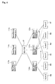
Fig. 4 , description will be made on the ability of the foregoing embodiment to ensure the scalability between terminalresource control unit 110 and base stationresource control unit 120 shown inFig. 3 . - Terminal
resource control units 110a - 110c are connected to base stationresource control units 120a - 120c throughdevice 17 such as an IP router, a hub, or the like. Conventionally, since terminalresource control unit 110 and base stationresource control unit 120 have been incorporated in a single RNC device, additional RNCs must be provided for extension. However, since terminalresource control unit 110 is responsible for signalling processing such as a call processing, an increase in the amount of calls would result in insufficient processing capabilities of terminalresource control unit 110. In this event, the processing load can be readily distributed by newly adding terminal resource control unit(s) 110. - For example, assume an algorithm defined for use with two terminal
resource control units resource control unit 110a when the least significant digit of the terminal number n assigned to each mobile terminal is an even number, and directs the use ofterminal resource unit 110b when the least significant digit is an odd number. When this algorithm is applied for use with three terminalresource control units 110a - 110c, the processing capabilities can be readily enhanced approximately by a factor of 1.5 by modifying the algorithm to direct the use of terminalresource control unit 110c when the least significant digit of the terminal number is 0, 1, 2, or 3. - Other than the foregoing, base station
resource control unit 120 is also responsible for user data transfer, so that it could be short of the processing capabilities if each mobile terminal transfers an increased amount of data to be communicated. In this event, the processing load can be readily distributed by newly adding base station resource control unit(s) 120. For example, the transfer speed can be readily increased by a factor of 1.5 by modifying the configuration which comprises two base stationresource control units Nodes B 6a - 6f connected thereto to an enhanced configuration which comprises three base stationresource control units Nodes B 6a - 6f connected thereto. -
Fig. 5 illustrates a sequence in the mobile communication system illustrated inFigs. 3 and4 , which covers from a voice communication performed by a mobile terminal or terminal UE at step S1 using Node B#1 (6a) and base station resource control unit #1 (120a) to a request for a soft handover with Node B#2 (6b) made by terminal UE, and to the connection of a path between terminal UE andNode B# 2. - Terminal resource control unit #1 (110a) manages resources of base station resource
control unit # 1 andNode B# 1. Terminal resource control unit #2 (110b) in turn manages resources of base station resource control unit #2 (120b) andNode B# 2. - A request for a soft handover is communicated from terminal UE to terminal resource
control unit # 1 throughNode B# 1 and base station resourcecontrol unit # 1 as "MEASUREMENT REPORT (RRC)" at step S2. - Next, at step S3, terminal resource
control unit # 1 acquires the IP address for a soft handover to base station resourcecontrol unit # 1, and notifies base station resourcecontrol unit # 1 of the iP address together with "RADIO LINK SETUP REQUEST" based on megacop (IETF RFC3015). - Next, at step S4, base station resource
control unit # 1 responds based on megacop (IETF RFC3015) by sending "RADIO LINK SETUP RESPONSE" to terminal resourcecontrol unit # 1. - Next, at step S5, terminal resource
control unit # 1 transmits the IP address of base station resourcecontrol unit # 1, acquired for a soft handover, together with "RADIO LINK SETUP REQUEST (RNSAP)," to terminal resourcecontrol unit # 2 which managesNode B# 2 to which terminal UE should be handed over. - Next, at steps S6, S7, terminal resource
control unit # 2 transmits the IP address of base station resourcecontrol unit # 1, acquired for a soft handover, together with "RADIO LINK SETUP REQUEST (NBAP)", toNode B# 2 through base station resourcecontrol unit # 2. - Next, at steps S8, S9, when
Node B# 2 notifies terminal resourcecontrol unit # 2 of "RADIO LINK SETUP REQUEST (NBAP),"Node B# 2 notifies terminal resourcecontrol unit # 2 of the IP address ofNode B# 2 through base station resourcecontrol unit # 2. - Next, at step S10, terminal resource
control unit # 2 notifies terminal resource control unit W1 of the IP address of Node B together with "RADIO LINK SETUP REQUEST (RNSAP)." - Next, at step S11, terminal resource
control unit # 1 notifies base station resourcecontrol unit # 1 of the IP address ofNode B# 2 through "RADIO LINK SETUP INDICATION." - These means cause the IP address of
Node B# 2 to be notified to base station resourcecontrol unit # 1, and the IP address of base station resourcecontrol unit # 1 to be notified toNode B# 2, resulting in a situation in which user data can be communicated. Simultaneously with this, at step S12, terminal resourcecontrol unit # 1 notifies terminal UE of "ACTIVE SET UPDATE (RRC).". - Next, at step S13, "ACTIVE SET UPDATE COMPLETE (RRC)" is notified from terminal UE to terminal resource
control unit # 1. This causes the start of radio synchronization between terminal UE andNode B# 2 at step S14. - After completion of the layer-1 synchronization for a radio link between terminal UE and
Node B# 2,Node B# 2 notifies terminal resourcecontrol unit # 2 of "RADIO LINK RESTORE INDICATION (NBAP)" through base station resourcecontrol unit # 2 at steps S15, S16. - Next, at step S17, terminal resource
control unit # 2 transmits "RADIO LINK RESTORE INDICATION (RNSAP)" to terminal resourcecontrol unit # 1. Thus, a setting is completed for a path between terminal UE andNode B# 2, followed by step S18 at which a soft handover path is set for connecting terminal UE to one base station resourcecontrol unit # 1 throughNode B# 1 andNode B# 2. - In this way, for setting a soft handover path across RNCs, the mobile communication system of the foregoing embodiment connects paths from a single base station resource control unit to a plurality of Nodes B, without setting a path between the drift RNC and serving RNC with respect to user data, as is the case with the prior art, thereby enabling the soft handover. Consequently, the mobile communication system of this embodiment can continuously utilize the same base station resource control unit, eliminate a path between RNCs, effectively utilize resources, and prevent a delay caused by passing through RNCs.
- An exemplary modification may be made to the foregoing, wherein the RNC is separated into a terminal resource control unit and a base station resource control unit, and the base station resource control unit is incorporated in Node B. In this modification, when the base station resource control unit incorporated in the Node B does not have a function of selectively composing user data, no soft handover can be carried out through a plurality of Nodes B. It can be said that this abandons the advantage provided by using CDMA in a radio section. To address this inconvenience, each Node B may be provided with a function of selectively composing user data to make communications between Nodes B.
- In the network configuration illustrated in
Fig. 6 , when a soft handover under way involves a plurality ofNodes B 6a - 6c, SRNC (serving RNC) 4 terminates user data and control signals. On the other hand, when a soft handover under way involves a plurality of RNCs, user data and control signals are transferred from DRNC (drift RNC) 4a toSRNC 4b through interface lur. -
Fig. 7 is a schematic diagram illustrating the configuration of a network in which the RNC is divided into terminalresource control unit 110 and base stationresource control units 120a - 120c, and the base stationresource control units 120a - 120c are incorporated inNodes B 6a - 6c, respectively. -
Node B 6a-6c, terminalresource control unit 110 and CN3 are connected each other through IP network. - The following description will be focused on how a handover is carried out including a plurality of Nodes B. Assume herein that terminal
resource control unit 110 knows the IP address of each Node B. -
Fig. 8 is a flow diagram representing an example, wherein terminal UE, which has had no radio link (RL), sets a radio link (RL) through two Nodes B. - First, at
step 20, the terminal resource control unit selects Node B, which is assigned to be a serving node (Node B# 1 inFig. 8 ), from a plurality of Nodes B (Node B# 1 andNode B# 2 inFig. 8 ). - Next, at steps S21, S22, the terminal resource control unit notifies each Node B of the ID address of the serving Node B (
Node B# 1 inFig. 8 ) and the ID address of the other Node B (Node B# 2 inFig. 8 ) through a "Radio Link Setup Request" message in such a manner that the difference between the two ID addresses is perceivable. - The terminal resource control unit specifies a Node B which controls the cell of the highest quality as the serving Node B. At step S23, each Node B compares its own IP address with the IP address of the serving Node B, and recognizes that the Node B itself is the serving Node B when its own IP address is equal to the IP address of the serving Node B.
- The remaining Nodes B recognize at step S24 that the IP address of the serving Node B is the destination of UL (uplink) data.
- After ensuring resources required for setting a radio link, each Node B transmits a "Radio Link Setup Response" message back to the terminal resource control unit at steps S25, S26.
- Subsequently, at step S27, the synchronization of U-plane is established.
- At step S28, for a DL (downlink) data transfer, the serving Node B transfers data to the IP addresses of other Nodes B which have been notified thereto through the "Radio Link Setup Request" message at step S29.
- For a UL (uplink) data transfer, the serving Node B compares data received from the respective Nodes B at step S30 to transfer the data of the highest quality to a higher rank.
-
Fig. 9 is a flow diagram representing an example, wherein a mobile terminal, which already has a radio link, newly adds a radio link through a Node B to result in a soft handover situation. - In this event, it is necessary to notifies the IP address of the serving Node B and the IP addresses of Nodes B included in a soft handover to a Node B (
Node B# 2 inFig. 9 ) for which a radio link has been set at step S31. - In doing so, first, at steps S32 - S34, a radio link is set for a new Node B (
Node B# 1 inFig. 9 ) using a "Radio Link Setup Request" message and a "Radio Link Setup Response" message, followed by a notification of the IP address of the serving Node B and the IP addresses of Nodes B involved in the soft handover to all the Nodes B involved in the soft handover. - As a means for this purpose, a "Soft Handover Indication" message is newly proposed at steps S36, S37.
- This message contains the IP address of the serving Node B and the IP addresses of Nodes B involved in the soft handover. The subsequent operations are similar to those in
Fig. 8 , and therefore are designated the same reference numerals. - While the sequences shown in
Figs. 8 and9 give an example of a soft handover which involves two Nodes B, the foregoing mechanism can be applied as well when more than two Nodes B are involved in a soft handover. In this event, a plurality of IP addresses should be set in "Other Node B IP addresses" at steps S36, S37 inFigs. 8 and9 . -
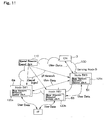
Fig. 10 is a diagram illustrating an exemplary flow of user data and control signals in an IP network, corresponding to the sequence ofFig. 9 . - While an example has been given for Nodes B, each of which is provided with a selective composition function, the manufacturing cost of the Node B is disadvantageously increased if each Node B is provided with the selective composition function. To solve this problem, only one of a plurality of Nodes B may be provided with the selective composition function. In this event, in a soft handover through a plurality of Nodes B, user data is terminated by a Node B which has the selective composition function. By doing so, it is possible to maintain a soft handover function which is a feature of CDMA.
-
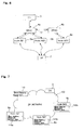
Fig. 11 is a diagram illustrating another exemplary flow of user data and control signals inIP network 100 in a mobile communication system. - While
Node B# 1 andNode B# 2 are involved in a soft handover,Fig. 11 illustrates the flow of user data and control signal inIP network 100 when neitherNode B# 1 norNode B# 2 has the function of performing the selective composition, but Node B#3 (6c) has the selective composition function. - The processing as illustrated is implemented on the premise that
CN 3 knows information such as the IP addresses and positions of all Nodes B included inIP network 100, whether or not each Node B has the selective composition function, how each Node B is loaded, and the like. In the flow illustrated inFig. 11 ,CN 3 notifiesNode B# 1,Node B# 2 of the IP address of a serving Node B, whileNode B# 1,Node B# 2 transfer data to the serving Node B. Also,CN 3 instructsNode B# 3 to function as a serving Node B. - For selecting a serving Node B from a Node B other than those involved in a soft handover,
CN 3 takes into account the physical distance between each of the Nodes B involved in the soft handover and a Node B which functions as a serving Node B, and the loading of the serving Node B. - As described above, the present invention can build a highly scalable system configuration, while the radio transmission scheme dependent control is fully performed by the second control means, so that no need exists for communicating signals between the first control means and second control means for controlling radio accesses, thereby alleviating the complicated communications of signals between devices.
- Also, when applied to mobile communication systems which employ different radio schemes, the second control means as much as the number of the radio transmission schemes may be provided for performing the control consistent with the respective radio transmission schemes, while the first control means controls all the second control means in common, enabling the mobile communication system of the present invention to support multiple areas in a small scale.
- While a preferred embodiment of the present invention has been described in specific terms, such description is for illustrative purposes only, and it is to be understood that changes and variations may be made without departing from the scope of the following claims.
Claims (7)
- A mobile communication system comprising:a terminal resource controller (110) being adapted to perform a control independent of a radio transmission scheme; anda plurality of base station resource controllers (120) being adapted to perform the control dependent on the radio transmission scheme,wherein said terminal resource controller is adapted to manage said plurality of base station resource controllers;
characterized in that
said terminal resource controller comprises:a terminal position detector (101) being adapted to collect and calculate the positions of mobile terminals;a common radio resource manager (102) being adapted to manage a radio access network environment to optimize a network load;a broadcast network device (103) being adapted to control the flow of radio broadcast/multicast and to communicate the state of the radio broadcast/multicast;a mobile controller (105) being adapted to establish and release acommunication channel;and each of said plurality of base station resource controllers comprises:a cell controller (104) being adapted to control permission of a radio access to each radio base station;a radio layer controller (106) being adapted to generate positional information on mobile terminals, to encode and decode radio channels or to control the power of radio links;a cell communication gateway (107) being adapted to transmit individual radio channel signals and to multiplex/demultiplex common radio channel signals; anda user radio gateway (108) being responsible for an encryption anddecryption of radio channels, compression of a header, multiplexing/ demultiplexing, and retransmission control. - The mobile communication system according to claim 1, further comprising:switching equipment,wherein said terminal resource controller is connected to said plurality of base station resource controllers through said switching equipment.
- The mobile communications system according to claim 2, wherein said switching equipment is a router or a hub.
- The mobile communications system according to one of claims 1 to 3,
wherein said terminal resource controller is physically separated from said plurality of base station resource controllers. - The mobile communications system according to one of claims 1 to 4,
wherein each of plurality of base station resource controllers is incorporated into a base station. - The mobile communications system according to one of claims 1 to 5, further comprising:a mobile terminal (2).
- A method of controlling a mobile communications system, comprising:performing a control independent of a radio transmission scheme by a terminal resource controller (110) in the mobile communications system;performing a control dependent on the radio transmission scheme by a plurality of base station resource controllers (120) in the mobile communications system, andmanaging said plurality of base station resource controllers by said terminal resource controller,characterized in that
said terminal resource controller is implemented by components for controlling terminal resource including a terminal position detector (101), a common radio resource manager (102), a broadcast network device (103), and a mobile controller (105);
each of said base station resource controllers is implemented by components for controlling base station resources and includes a cell controller (104), a radio layer controller (106), a cell communication gateway (107), and a user radio gateway (108); and
wherein said method further comprises:collecting and calculating the position of terminals by the terminal position detector;managing a radio access network environment to optimize a network load by the common radion resource manager;controlling the flow of radio broadcast/multicast and communcating the state of the radio broadcast/multicast by the broadcast network device;controlling permission of a radio access to each radio base station device by the cell controll;establishing and releasing a communication channel by the mobile controller;transmitting individual radio channel signals and multiplexing/ demultiplexing common radio channel signals by the cell communication gateway;carrying out encryption and decryption of radio channels, compression of a header, multiplexing/demultiplexing, and retransmission control by the user radio gateway; andgenerating positional information on terminal, encoding and decoding radio channels or controlling the power of radio links by the radio layer controller.
Applications Claiming Priority (2)
| Application Number | Priority Date | Filing Date | Title |
|---|---|---|---|
| JP2002360858A JP4092562B2 (en) | 2002-12-12 | 2002-12-12 | Mobile communication system, terminal resource control unit, base station resource control unit, and control methods thereof |
| EP03028763A EP1429567B1 (en) | 2002-12-12 | 2003-12-12 | Improved OpenRAN architecture for Radio Network Controller, Mobile Communication System and method of controlling Radio Base Station device |
Related Parent Applications (1)
| Application Number | Title | Priority Date | Filing Date |
|---|---|---|---|
| EP03028763A Division EP1429567B1 (en) | 2002-12-12 | 2003-12-12 | Improved OpenRAN architecture for Radio Network Controller, Mobile Communication System and method of controlling Radio Base Station device |
Publications (3)
| Publication Number | Publication Date |
|---|---|
| EP1705935A2 EP1705935A2 (en) | 2006-09-27 |
| EP1705935A3 EP1705935A3 (en) | 2006-10-11 |
| EP1705935B1 true EP1705935B1 (en) | 2009-07-22 |
Family
ID=32322122
Family Applications (4)
| Application Number | Title | Priority Date | Filing Date |
|---|---|---|---|
| EP03028763A Expired - Fee Related EP1429567B1 (en) | 2002-12-12 | 2003-12-12 | Improved OpenRAN architecture for Radio Network Controller, Mobile Communication System and method of controlling Radio Base Station device |
| EP06124086A Withdrawn EP1763265A3 (en) | 2002-12-12 | 2003-12-12 | Improved OpenRAN architecture for Radio Network Controller, Mobile Communication System and method of controlling Radio Base Station device |
| EP06124084A Withdrawn EP1763264A3 (en) | 2002-12-12 | 2003-12-12 | Improved OpenRAN architecture for Radio Network Controller, Mobile Communication System and method of controlling Radio Base Station device |
| EP06112355A Expired - Fee Related EP1705935B1 (en) | 2002-12-12 | 2003-12-12 | Improved OpenRAN architecture for a Mobile Communication System and method of controlling a Mobile Communication System |
Family Applications Before (3)
| Application Number | Title | Priority Date | Filing Date |
|---|---|---|---|
| EP03028763A Expired - Fee Related EP1429567B1 (en) | 2002-12-12 | 2003-12-12 | Improved OpenRAN architecture for Radio Network Controller, Mobile Communication System and method of controlling Radio Base Station device |
| EP06124086A Withdrawn EP1763265A3 (en) | 2002-12-12 | 2003-12-12 | Improved OpenRAN architecture for Radio Network Controller, Mobile Communication System and method of controlling Radio Base Station device |
| EP06124084A Withdrawn EP1763264A3 (en) | 2002-12-12 | 2003-12-12 | Improved OpenRAN architecture for Radio Network Controller, Mobile Communication System and method of controlling Radio Base Station device |
Country Status (5)
| Country | Link |
|---|---|
| US (2) | US20040127258A1 (en) |
| EP (4) | EP1429567B1 (en) |
| JP (1) | JP4092562B2 (en) |
| CN (1) | CN100583688C (en) |
| DE (2) | DE60328542D1 (en) |
Families Citing this family (13)
| Publication number | Priority date | Publication date | Assignee | Title |
|---|---|---|---|---|
| JP3988043B2 (en) | 2002-12-12 | 2007-10-10 | 日本電気株式会社 | Radio access network control method and radio access network |
| JP3972198B2 (en) | 2002-12-12 | 2007-09-05 | 日本電気株式会社 | Cell information setting method, radio access network, and radio control apparatus |
| JP4206742B2 (en) * | 2002-12-12 | 2009-01-14 | 日本電気株式会社 | Radio control apparatus, mobile communication system using the same, and operation control method thereof |
| CN1833456A (en) * | 2003-04-14 | 2006-09-13 | 日本电气株式会社 | Mobile communication system, radio base station replacement control device in the mobile communication system and control method thereof |
| KR100770857B1 (en) * | 2004-02-12 | 2007-10-26 | 삼성전자주식회사 | Method for resuming header re-compression multimedia broadcast multicast service system |
| CN100450246C (en) * | 2005-03-23 | 2009-01-07 | 华为技术有限公司 | Method for checking transmission channel collocation parameter |
| US8391153B2 (en) * | 2006-02-17 | 2013-03-05 | Cisco Technology, Inc. | Decoupling radio resource management from an access gateway |
| CN101401462B (en) * | 2006-02-17 | 2012-07-04 | 思科技术公司 | Optimal home agent allocation |
| CN101496387B (en) * | 2006-03-06 | 2012-09-05 | 思科技术公司 | System and method for access authentication in a mobile wireless network |
| CN101123549B (en) * | 2006-08-11 | 2010-05-12 | 华为技术有限公司 | Access network system with separated control and carrier and its communication implementation method |
| CN101489231B (en) * | 2008-01-15 | 2010-09-29 | 上海贝尔阿尔卡特股份有限公司 | Inter cell interference control method and apparatus in wireless communication network |
| EP2832076B1 (en) * | 2012-03-30 | 2018-05-02 | Nokia Solutions and Networks Oy | Centralized ip address management for distributed gateways |
| JP6256024B2 (en) * | 2014-01-16 | 2018-01-10 | 富士通株式会社 | Radio base station and radio base station transmission power control method |
Family Cites Families (11)
| Publication number | Priority date | Publication date | Assignee | Title |
|---|---|---|---|---|
| US6684256B1 (en) * | 2000-01-27 | 2004-01-27 | Utstarcom, Inc. | Routing method for mobile wireless nodes having overlapping internet protocol home addresses |
| US6738625B1 (en) * | 2000-05-11 | 2004-05-18 | Telefonaktiebolaget Lm Ericsson (Publ) | Rehoming and resource sharing in communications networks |
| DE10105093A1 (en) * | 2001-02-05 | 2002-08-08 | Nokia Corp | Paging method and system for a radio access network |
| US6970716B2 (en) * | 2001-02-22 | 2005-11-29 | Telefonaktiebolaget Lm Ericsson (Publ) | Power control for downlink shared channel in radio access telecommunications network |
| US6954441B2 (en) * | 2001-07-12 | 2005-10-11 | Telefonaktiebolaget Lm Ericsson (Publ) | IP-based GSM and UMTS system |
| US6957071B1 (en) * | 2001-07-18 | 2005-10-18 | Cisco Technology, Inc. | Method and system for managing wireless bandwidth resources |
| JP3926798B2 (en) * | 2002-03-13 | 2007-06-06 | 三菱電機株式会社 | Wireless area network control system and wide area wireless area network control system |
| US7489672B2 (en) * | 2002-03-26 | 2009-02-10 | Interdigital Technology Corp. | RLAN wireless telecommunication system with RAN IP gateway and methods |
| US7336631B2 (en) * | 2002-03-29 | 2008-02-26 | Mitsubishi Denki Kabushiki Kaisha | Radio network system and radio communication control method |
| EP1510095B1 (en) * | 2002-06-05 | 2010-08-04 | Nokia Corporation | Handover in a communication network |
| EP1372349A1 (en) * | 2002-06-11 | 2003-12-17 | Alcatel | Radio access network architecture and paging method |
-
2002
- 2002-12-12 JP JP2002360858A patent/JP4092562B2/en not_active Expired - Fee Related
-
2003
- 2003-12-11 US US10/735,193 patent/US20040127258A1/en not_active Abandoned
- 2003-12-12 EP EP03028763A patent/EP1429567B1/en not_active Expired - Fee Related
- 2003-12-12 DE DE60328542T patent/DE60328542D1/en not_active Expired - Lifetime
- 2003-12-12 EP EP06124086A patent/EP1763265A3/en not_active Withdrawn
- 2003-12-12 DE DE60311949T patent/DE60311949T2/en not_active Expired - Lifetime
- 2003-12-12 EP EP06124084A patent/EP1763264A3/en not_active Withdrawn
- 2003-12-12 EP EP06112355A patent/EP1705935B1/en not_active Expired - Fee Related
- 2003-12-12 CN CN200310118557A patent/CN100583688C/en not_active Expired - Fee Related
-
2007
- 2007-05-16 US US11/749,216 patent/US20070213097A1/en not_active Abandoned
Also Published As
| Publication number | Publication date |
|---|---|
| EP1705935A2 (en) | 2006-09-27 |
| US20040127258A1 (en) | 2004-07-01 |
| DE60311949T2 (en) | 2007-11-08 |
| DE60328542D1 (en) | 2009-09-03 |
| EP1705935A3 (en) | 2006-10-11 |
| EP1763265A2 (en) | 2007-03-14 |
| US20070213097A1 (en) | 2007-09-13 |
| EP1429567A1 (en) | 2004-06-16 |
| EP1763264A3 (en) | 2007-03-28 |
| CN100583688C (en) | 2010-01-20 |
| EP1763264A2 (en) | 2007-03-14 |
| EP1429567B1 (en) | 2007-02-21 |
| DE60311949D1 (en) | 2007-04-05 |
| JP2004194073A (en) | 2004-07-08 |
| EP1763265A3 (en) | 2007-03-28 |
| CN1507173A (en) | 2004-06-23 |
| JP4092562B2 (en) | 2008-05-28 |
Similar Documents
| Publication | Publication Date | Title |
|---|---|---|
| JP4973588B2 (en) | Mobile communication system | |
| US20070213097A1 (en) | Radio network controller, mobile communication system, and method of controlling radio base station device | |
| US6782274B1 (en) | Method for transmitting radio resource control message in asynchronous mobile communication system | |
| JP4268634B2 (en) | Method and system for integrating resource allocation between TDD and FDD in a wireless communication system | |
| EP1269773B1 (en) | Relocation of serving radio network controller with signaling of linking of transport channels | |
| US8027676B2 (en) | Radio network controller and radio communications method | |
| JP2003189347A (en) | Method for switching between new base station and previous base station in wireless communications systems | |
| JP4198685B2 (en) | Mobile communication system and data distribution method in the system | |
| JP2002510915A (en) | Method of transferring a data signal in a wireless communication system | |
| KR20020003824A (en) | A method for providing multiple points of connectivity to subscribers of wireless communication networks | |
| US7142859B2 (en) | Protocol terminating method, control signal terminating server apparatus, and mobile communication system | |
| US7292839B2 (en) | Macrodiversity system with signal combining in the base station | |
| WO2006056127A1 (en) | A radio access network system and a method for realizing handover thereof | |
| JP2008109709A (en) | Mobile communication system | |
| JP5643365B2 (en) | Wireless communication system, user plane control apparatus and communication method therefor |
Legal Events
| Date | Code | Title | Description |
|---|---|---|---|
| PUAI | Public reference made under article 153(3) epc to a published international application that has entered the european phase |
Free format text: ORIGINAL CODE: 0009012 |
|
| PUAL | Search report despatched |
Free format text: ORIGINAL CODE: 0009013 |
|
| AC | Divisional application: reference to earlier application |
Ref document number: 1429567 Country of ref document: EP Kind code of ref document: P |
|
| AK | Designated contracting states |
Kind code of ref document: A2 Designated state(s): AT BE BG CH CY CZ DE DK EE ES FI FR GB GR HU IE IS IT LI LT LU LV MC NL PL PT RO SE SI SK TR |
|
| AX | Request for extension of the european patent |
Extension state: AL BA HR MK YU |
|
| AK | Designated contracting states |
Kind code of ref document: A3 Designated state(s): AT BE BG CH CY CZ DE DK EE ES FI FR GB GR HU IE IS IT LI LT LU LV MC NL PL PT RO SE SI SK TR |
|
| AX | Request for extension of the european patent |
Extension state: AL BA HR MK YU |
|
| 17P | Request for examination filed |
Effective date: 20070411 |
|
| AKX | Designation fees paid |
Designated state(s): DE GB |
|
| GRAP | Despatch of communication of intention to grant a patent |
Free format text: ORIGINAL CODE: EPIDOSNIGR1 |
|
| RIC1 | Information provided on ipc code assigned before grant |
Ipc: H04W 88/12 20090101AFI20090213BHEP |
|
| RTI1 | Title (correction) |
Free format text: IMPROVED OPENRAN ARCHITECTURE FOR MOBILE COMMUNICATION SYSTEM AND METHOD OF CONTROLLING A MOBILE COMMUNICATION SYSTEM |
|
| RTI1 | Title (correction) |
Free format text: IMPROVED OPENRAN ARCHITECTURE FOR A MOBILE COMMUNICATION SYSTEM AND METHOD OF CONTROLLING A MOBILE COMMUNICATION SYSTEM |
|
| GRAS | Grant fee paid |
Free format text: ORIGINAL CODE: EPIDOSNIGR3 |
|
| GRAA | (expected) grant |
Free format text: ORIGINAL CODE: 0009210 |
|
| AC | Divisional application: reference to earlier application |
Ref document number: 1429567 Country of ref document: EP Kind code of ref document: P |
|
| AK | Designated contracting states |
Kind code of ref document: B1 Designated state(s): DE GB |
|
| REG | Reference to a national code |
Ref country code: GB Ref legal event code: FG4D |
|
| REF | Corresponds to: |
Ref document number: 60328542 Country of ref document: DE Date of ref document: 20090903 Kind code of ref document: P |
|
| PLBE | No opposition filed within time limit |
Free format text: ORIGINAL CODE: 0009261 |
|
| STAA | Information on the status of an ep patent application or granted ep patent |
Free format text: STATUS: NO OPPOSITION FILED WITHIN TIME LIMIT |
|
| 26N | No opposition filed |
Effective date: 20100423 |
|
| PGFP | Annual fee paid to national office [announced via postgrant information from national office to epo] |
Ref country code: DE Payment date: 20171206 Year of fee payment: 15 |
|
| PGFP | Annual fee paid to national office [announced via postgrant information from national office to epo] |
Ref country code: GB Payment date: 20171206 Year of fee payment: 15 |
|
| REG | Reference to a national code |
Ref country code: DE Ref legal event code: R119 Ref document number: 60328542 Country of ref document: DE |
|
| GBPC | Gb: european patent ceased through non-payment of renewal fee |
Effective date: 20181212 |
|
| PG25 | Lapsed in a contracting state [announced via postgrant information from national office to epo] |
Ref country code: DE Free format text: LAPSE BECAUSE OF NON-PAYMENT OF DUE FEES Effective date: 20190702 |
|
| PG25 | Lapsed in a contracting state [announced via postgrant information from national office to epo] |
Ref country code: GB Free format text: LAPSE BECAUSE OF NON-PAYMENT OF DUE FEES Effective date: 20181212 |