EP1705934A1 - Wireless communication method, wireless communication system using the same, and wireless terminal thereof - Google Patents
Wireless communication method, wireless communication system using the same, and wireless terminal thereof Download PDFInfo
- Publication number
- EP1705934A1 EP1705934A1 EP05703864A EP05703864A EP1705934A1 EP 1705934 A1 EP1705934 A1 EP 1705934A1 EP 05703864 A EP05703864 A EP 05703864A EP 05703864 A EP05703864 A EP 05703864A EP 1705934 A1 EP1705934 A1 EP 1705934A1
- Authority
- EP
- European Patent Office
- Prior art keywords
- fdma
- repeater
- relay station
- wireless communication
- wireless terminal
- Prior art date
- Legal status (The legal status is an assumption and is not a legal conclusion. Google has not performed a legal analysis and makes no representation as to the accuracy of the status listed.)
- Withdrawn
Links
Images


Classifications
-
- H—ELECTRICITY
- H04—ELECTRIC COMMUNICATION TECHNIQUE
- H04W—WIRELESS COMMUNICATION NETWORKS
- H04W68/00—User notification, e.g. alerting and paging, for incoming communication, change of service or the like
- H04W68/12—Inter-network notification
-
- H—ELECTRICITY
- H04—ELECTRIC COMMUNICATION TECHNIQUE
- H04W—WIRELESS COMMUNICATION NETWORKS
- H04W88/00—Devices specially adapted for wireless communication networks, e.g. terminals, base stations or access point devices
- H04W88/02—Terminal devices
- H04W88/04—Terminal devices adapted for relaying to or from another terminal or user
-
- H—ELECTRICITY
- H04—ELECTRIC COMMUNICATION TECHNIQUE
- H04W—WIRELESS COMMUNICATION NETWORKS
- H04W88/00—Devices specially adapted for wireless communication networks, e.g. terminals, base stations or access point devices
- H04W88/02—Terminal devices
- H04W88/06—Terminal devices adapted for operation in multiple networks or having at least two operational modes, e.g. multi-mode terminals
Definitions
- the present invention relates to a wireless communication method for waiting for call signals from relay stations using different wireless communication systems, a wireless communication system using the same and a wireless terminal thereof.
- the present invention has been made to effectively solve the above problem in the conventional technique, and its object is to provide a wireless communication method for waiting for call signals of two different wireless communication systems with a single reception frequency, a wireless communication system using the same and a wireless terminal thereof.
- a wireless communication method is used in a wireless communication system which includes both a repeater relay station of a wireless communication network using repeater system and a frequency division multiple access (FDMA) relay station of a wireless communication network using FDMA system, and the method basically includes the following sequence of signal processing steps:
- a wireless communication system is such that includes both a repeater relay station of a wireless communication network using repeater system and an FDMA relay station of a wireless communication network using FDMA system, and it is basically configured by means for receiving a call signal from a repeater wireless terminal in the wireless communication network using repeater system, by the repeater relay station; means for forwarding the call signal received by the repeater relay station to the FDMA relay station; means for setting the forwarded call signal for a control signal at the FDMA relay station; means for transmitting the control signal to an FDMA wireless terminal in the wireless communication network using FDMA system; and means for the FDMA wireless terminal, which has received the control signal, to communicate with the repeater wireless terminal via the repeater relay station.
- a wireless terminal is an FDMA wireless terminal to be used in a business wireless communication system which includes both a repeater relay station of a wireless communication network using repeater system and an FDMA relay station of a wireless communication network using FDMA system, wherein the FDMA relay station sets a call signal from a repeater wireless terminal in the wireless communication network using repeater system, which has been forwarded from the repeater relay station, for a control signal; and the FDMA wireless terminal in the wireless communication network using FDMA system has means for receiving the control signal sent thereto to communicate with the repeater wireless terminal via the repeater relay station.
- FIG. 1 is a block diagram illustrating an embodiment of a business wireless communication system according to the present invention.
- the business wireless communication system is configured by a repeater relay station 1, an FDMA relay station 2, a repeater wireless terminal 3 and FDMA wireless terminals 4 and 5.
- the repeater relay station 1 is connected to the FDMA relay station 2 via a communication line 6, and it forwards a call signal via serial communication.
- the repeater wireless terminal 3 communicates with another repeater wireless terminal (not shown) in a wireless network using repeater system, via the repeater relay station 1 with the use of an uplink frequency f1 and a downlink frequency f2. Furthermore, it can communicate with the FDMA wireless terminals 4 and 5 via the repeater relay station 1.
- the FDMA wireless terminals 4 and 5 perform communication connection within a wireless network using FDMA system, via the FDMA relay station with an uplink control channel frequency f4 and a downlink control channel frequency f3. Furthermore, the FDMA wireless terminals 4 and 5 can communicate with the repeater wireless terminal 3 via the repeater relay station 1 with the uplink frequency f1 and the downlink frequency f2.
- the repeater wireless terminal 3 communicates with the FDMA wireless terminal 4.
- the repeater wireless terminal 3 transmits a call signal of the FDMA wireless terminal 4 on the uplink frequency f1 to the repeater relay station 1.
- the repeater relay station 1 serially forwards the signal to the FDMA relay station 2 via the communication line 6.
- the FDMA relay station 2 sets this call signal for a control signal of the downlink control channel frequency f3 and transmits it into the wireless network using FDMA system.
- the FDMA wireless terminal 4 in a waiting condition receives this call signal.
- the repeater relay station 1 detects the downlink frequency f2 of the repeater relay station 1 from reception frequency information set in the wireless terminal in advance, based on information about the call signal, and switches the downlink control channel frequency f3 to the downlink frequency f2.
- the repeater relay station 1 receives the signal which the repeater wireless terminal 3 has transmitted on the uplink frequency, forwards the call signal to the FDMA relay station 2, and relay-transmits a voice signal to the downlink frequency f2.
- the FDMA wireless terminal 4 which has switched the reception frequency to f2 receives the voice signal of the repeater wireless terminal 3 and starts communication.
- Figure 2 is a transition diagram illustrating the flow of a call signal and communication.
- Repeater wireless terminals communicate with each other with the uplink frequency f1 and the downlink frequency f2 via the repeater relay station.
- FDMA wireless terminals communicate with each other with the uplink control channel frequency f4 and the downlink control channel frequency f3 via the FDMA relay station.
- Communication between a repeater wireless terminal and an FDMA wireless terminal is started by the repeater relay station receiving a call signal of the repeater wireless terminal and serially forwarding it to the FDMA relay station, the FDMA relay station transmitting it on the downlink control channel frequency f3 to the FDMA wireless terminal, and the FDMA wireless terminal receiving it and changing the reception frequency from f3 to f2.
- the FDMA wireless terminal acquires connection information from the frequency f3.
- connection with the repeater wireless terminal is established, communication is performed in a wireless communication network using repeater system.
- Figure 3 is a diagram illustrating a call signal format to be used by a wireless terminal and a relay station to perform connection.
- A indicates a call signal format for a repeater wireless terminal or an FDMA wireless terminal, and it is configured by a call classifier and a terminal identifier.
- B indicates a call signal format used by a repeater relay station for forwarding to an FDMA relay station, and it is configured by a synchronous signal pattern, a call classifier, a terminal identifier, a relay station identifier and information added by the relay station.
- C indicates a call signal format used by an FDMA relay station for transmission into the wireless network using FDMA system, and it is configured by a synchronous signal pattern, system information and terminal control information.
- the FDMA wireless terminal 5 transmits a call classifier indicating an individual call, a broadcast notification or the like and an identifier such as an individual number and a broadcast number on the uplink control channel frequency f4, to the FDMA relay station 2 (A).
- the FDMA relay station 2 sets this call signal for terminal control information of a control signal of the downlink control channel frequency f3 and transmits it into the wireless network using FDMA system (C).
- the FDMA wireless terminal 4 in a waiting condition receives this call signal. Communication with the FDMA wireless terminal 5 is started through an FDMA voice channel.
- the repeater wireless terminal 3 transmits a call classifier indicating an individual call, a broadcast notification or the like and an identifier such as an individual number and a broadcast number on the uplink frequency f1, to the repeater relay station 1 (A).
- the repeater relay station 1 After receiving this call signal, the repeater relay station 1 adds an identifier indicating the type of the relay station and information for communication with the relay station such as a frequency to this signal, and serially transmits the signal to the FDMA relay station 2 via the communication line 6 (B).
- the FDMA relay station 2 sets this call signal for terminal control information of a control signal of the downlink control channel frequency f3 and transmits it into the wireless network using FDMA system (C).
- the FDMA wireless terminal 4 in a waiting condition receives this call signal.
- the synchronous signal pattern, the system information and the terminal control information are transmitted in a constant repetition cycle.
- the FDMA relay station 2 sets the signal for the terminal control information and transmits it into the wireless network using FDMA system, in order of receipt. Based on whether the call is via a wireless communication network using repeater system or via the wireless communication network using FDMA system, information required by the communication system is set for the system information.
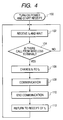
- FIG 4 is a flowchart showing the flow of an FDMA wireless terminal communicating with a repeater wireless terminal.
- the FDMA wireless terminal is powered on to start receiving (step 100).
- the FDMA wireless terminal waits for a call with the downlink control channel frequency f3 (step 102). If there is a call from a wireless terminal, the FDMA wireless terminal proceeds to the next step (step 104). If the call is from a repeater wireless terminal, then the reception frequency is changed from f3 to f2 (step 106). If the call is from an FDMA wireless terminal, then communication is started via an FDMA-based voice channel (not shown). A message from the repeater wireless terminal is received with the downlink frequency f2, and call communication is performed (step 108). The call communication ends (step 110). The FDMA wireless terminal returns to the reception frequency of the downlink control channel frequency f3 and enters a condition of waiting for a call signal (step 112).
- FDMA wireless terminal since it is possible to wait for both of a call from a wireless communication network using repeater system and a call from a wireless communication network using FDMA system with a single reception frequency, wireless communication without call loss is possible.
- Switching of the frequency of an FDMA wireless terminal may be performed by any circuit if it is means for realizing the function, and it is also possible to realize a part or all of the function by software.
- a wireless communication method for waiting for call signals from relay stations using different wireless communication systems can be effectively used in a business wireless communication system which includes both a repeater relay station of a wireless network using repeater system and an FDMA relay station of a wireless network using FDMA system.
Landscapes
- Engineering & Computer Science (AREA)
- Computer Networks & Wireless Communication (AREA)
- Signal Processing (AREA)
- Mobile Radio Communication Systems (AREA)
- Radio Relay Systems (AREA)
Abstract
Description
- The present invention relates to a wireless communication method for waiting for call signals from relay stations using different wireless communication systems, a wireless communication system using the same and a wireless terminal thereof.
- In a business wireless communication system, when replacing the existing system with a new system, it is often difficult to replacing everything including wireless terminals and a wireless relay system, from a viewpoint of cost or a viewpoint of keeping the stability of the system. Therefore, a method is adopted in which a lot of time is spent for transition to the new system. During the transition period, however, wireless terminals operating on the two different systems are required to alternatively receive signals of both of the systems to wait for a call thereto. In this case, there is a problem that, if there is any system that has to always wait for a signal from a relay station, and there is a call from the system while a wireless terminal is waiting for a signal from the other system, the wireless terminal cannot receive the call. As a method for extending a function by utilizing a control channel signal, a method for changing a control channel to a voice channel, for example, is proposed in
Japanese Patent No. 2724917 - The present invention has been made to effectively solve the above problem in the conventional technique, and its object is to provide a wireless communication method for waiting for call signals of two different wireless communication systems with a single reception frequency, a wireless communication system using the same and a wireless terminal thereof.
- In order to achieve the above object of the invention, a wireless communication method according to a first aspect of the present invention is used in a wireless communication system which includes both a repeater relay station of a wireless communication network using repeater system and a frequency division multiple access (FDMA) relay station of a wireless communication network using FDMA system, and the method basically includes the following sequence of signal processing steps:
- · receiving a call signal from a repeater wireless terminal in the wireless communication network using repeater system, by the repeater relay station;
- · forwarding the call signal received by the repeater relay station to the FDMA relay station;
- · setting the forwarded call signal for a control signal at the FDMA relay station;
- · transmitting the control signal to an FDMA wireless terminal in the wireless communication network using FDMA system; and
- · the FDMA wireless terminal, which has received the control signal, communicating with the repeater wireless terminal via the repeater relay station.
- A wireless communication system according to a second aspect of the present invention is such that includes both a repeater relay station of a wireless communication network using repeater system and an FDMA relay station of a wireless communication network using FDMA system, and it is basically configured by means for receiving a call signal from a repeater wireless terminal in the wireless communication network using repeater system, by the repeater relay station; means for forwarding the call signal received by the repeater relay station to the FDMA relay station; means for setting the forwarded call signal for a control signal at the FDMA relay station; means for transmitting the control signal to an FDMA wireless terminal in the wireless communication network using FDMA system; and means for the FDMA wireless terminal, which has received the control signal, to communicate with the repeater wireless terminal via the repeater relay station.
- A wireless terminal according to a third aspect of the present invention is an FDMA wireless terminal to be used in a business wireless communication system which includes both a repeater relay station of a wireless communication network using repeater system and an FDMA relay station of a wireless communication network using FDMA system, wherein the FDMA relay station sets a call signal from a repeater wireless terminal in the wireless communication network using repeater system, which has been forwarded from the repeater relay station, for a control signal; and the FDMA wireless terminal in the wireless communication network using FDMA system has means for receiving the control signal sent thereto to communicate with the repeater wireless terminal via the repeater relay station.
- According to the wireless-communication-related technical approach of the present invention, it is possible to wait for call signals of two different wireless communication systems with a single reception frequency.
-
- Figure 1 is a block diagram illustrating an embodiment of a business wireless communication system according to the present invention;
- Figure 2 is a transition diagram illustrating the flow of a call signal and communication of the present invention;
- Figure 3 is a diagram illustrating a call signal format according to the present invention; and
- Figure 4 is a flowchart showing the flow of communication according to the present invention.
- An embodiment of the present invention will be described below in detail with reference to drawings.
- Figure 1 is a block diagram illustrating an embodiment of a business wireless communication system according to the present invention. The business wireless communication system is configured by a repeater relay station 1, an
FDMA relay station 2, a repeaterwireless terminal 3 and FDMAwireless terminals FDMA relay station 2 via acommunication line 6, and it forwards a call signal via serial communication. The repeaterwireless terminal 3 communicates with another repeater wireless terminal (not shown) in a wireless network using repeater system, via the repeater relay station 1 with the use of an uplink frequency f1 and a downlink frequency f2. Furthermore, it can communicate with the FDMAwireless terminals wireless terminals wireless terminals wireless terminal 3 via the repeater relay station 1 with the uplink frequency f1 and the downlink frequency f2. - Description will be made on a case where the repeater
wireless terminal 3 communicates with the FDMAwireless terminal 4. The repeaterwireless terminal 3 transmits a call signal of the FDMAwireless terminal 4 on the uplink frequency f1 to the repeater relay station 1. After receiving this call signal, the repeater relay station 1 serially forwards the signal to theFDMA relay station 2 via thecommunication line 6. TheFDMA relay station 2 sets this call signal for a control signal of the downlink control channel frequency f3 and transmits it into the wireless network using FDMA system. The FDMAwireless terminal 4 in a waiting condition receives this call signal. Furthermore, it detects the downlink frequency f2 of the repeater relay station 1 from reception frequency information set in the wireless terminal in advance, based on information about the call signal, and switches the downlink control channel frequency f3 to the downlink frequency f2. The repeater relay station 1 receives the signal which the repeaterwireless terminal 3 has transmitted on the uplink frequency, forwards the call signal to theFDMA relay station 2, and relay-transmits a voice signal to the downlink frequency f2. Accordingly, the FDMAwireless terminal 4 which has switched the reception frequency to f2 receives the voice signal of the repeaterwireless terminal 3 and starts communication. - Figure 2 is a transition diagram illustrating the flow of a call signal and communication. Repeater wireless terminals communicate with each other with the uplink frequency f1 and the downlink frequency f2 via the repeater relay station. FDMA wireless terminals communicate with each other with the uplink control channel frequency f4 and the downlink control channel frequency f3 via the FDMA relay station. Communication between a repeater wireless terminal and an FDMA wireless terminal is started by the repeater relay station receiving a call signal of the repeater wireless terminal and serially forwarding it to the FDMA relay station, the FDMA relay station transmitting it on the downlink control channel frequency f3 to the FDMA wireless terminal, and the FDMA wireless terminal receiving it and changing the reception frequency from f3 to f2. Here, the FDMA wireless terminal acquires connection information from the frequency f3. When connection with the repeater wireless terminal is established, communication is performed in a wireless communication network using repeater system.
- Figure 3 is a diagram illustrating a call signal format to be used by a wireless terminal and a relay station to perform connection. A indicates a call signal format for a repeater wireless terminal or an FDMA wireless terminal, and it is configured by a call classifier and a terminal identifier. B indicates a call signal format used by a repeater relay station for forwarding to an FDMA relay station, and it is configured by a synchronous signal pattern, a call classifier, a terminal identifier, a relay station identifier and information added by the relay station. C indicates a call signal format used by an FDMA relay station for transmission into the wireless network using FDMA system, and it is configured by a synchronous signal pattern, system information and terminal control information.
- To perform communication between FDMA wireless terminals, the FDMA
wireless terminal 5 transmits a call classifier indicating an individual call, a broadcast notification or the like and an identifier such as an individual number and a broadcast number on the uplink control channel frequency f4, to the FDMA relay station 2 (A). After receiving this call signal, theFDMA relay station 2 sets this call signal for terminal control information of a control signal of the downlink control channel frequency f3 and transmits it into the wireless network using FDMA system (C). The FDMAwireless terminal 4 in a waiting condition receives this call signal. Communication with the FDMAwireless terminal 5 is started through an FDMA voice channel. - The repeater
wireless terminal 3 transmits a call classifier indicating an individual call, a broadcast notification or the like and an identifier such as an individual number and a broadcast number on the uplink frequency f1, to the repeater relay station 1 (A). After receiving this call signal, the repeater relay station 1 adds an identifier indicating the type of the relay station and information for communication with the relay station such as a frequency to this signal, and serially transmits the signal to theFDMA relay station 2 via the communication line 6 (B). TheFDMA relay station 2 sets this call signal for terminal control information of a control signal of the downlink control channel frequency f3 and transmits it into the wireless network using FDMA system (C). The FDMAwireless terminal 4 in a waiting condition receives this call signal. - In the call signal pattern C in Figure 3, the synchronous signal pattern, the system information and the terminal control information are transmitted in a constant repetition cycle. When receiving a call signal from a repeater wireless terminal or an FDMA wireless terminal, the
FDMA relay station 2 sets the signal for the terminal control information and transmits it into the wireless network using FDMA system, in order of receipt. Based on whether the call is via a wireless communication network using repeater system or via the wireless communication network using FDMA system, information required by the communication system is set for the system information. - Figure 4 is a flowchart showing the flow of an FDMA wireless terminal communicating with a repeater wireless terminal. The FDMA wireless terminal is powered on to start receiving (step 100). The FDMA wireless terminal waits for a call with the downlink control channel frequency f3 (step 102). If there is a call from a wireless terminal, the FDMA wireless terminal proceeds to the next step (step 104). If the call is from a repeater wireless terminal, then the reception frequency is changed from f3 to f2 (step 106). If the call is from an FDMA wireless terminal, then communication is started via an FDMA-based voice channel (not shown). A message from the repeater wireless terminal is received with the downlink frequency f2, and call communication is performed (step 108). The call communication ends (step 110). The FDMA wireless terminal returns to the reception frequency of the downlink control channel frequency f3 and enters a condition of waiting for a call signal (step 112).
- As described above, according to the present invention, since it is possible to wait for both of a call from a wireless communication network using repeater system and a call from a wireless communication network using FDMA system with a single reception frequency, wireless communication without call loss is possible. Switching of the frequency of an FDMA wireless terminal may be performed by any circuit if it is means for realizing the function, and it is also possible to realize a part or all of the function by software.
- According to the present invention, there is provided a wireless communication method for waiting for call signals from relay stations using different wireless communication systems. This method can be effectively used in a business wireless communication system which includes both a repeater relay station of a wireless network using repeater system and an FDMA relay station of a wireless network using FDMA system.
Claims (3)
- A communication method used in a wireless communication system which includes both a repeater relay station of a wireless communication network using repeater system and a frequency division multiple access (FDMA) relay station of a wireless communication network using FDMA system, the method comprising the steps of:receiving a call signal from a repeater wireless terminal in the wireless communication network using repeater system, by the repeater relay station;forwarding the call signal received by the repeater relay station to the FDMA relay station;setting the forwarded call signal for a control signal at the FDMA relay station;transmitting the control signal to an FDMA wireless terminal in the wireless communication network using FDMA system; andperforming communication via the via the repeater relay station between the FDMA wireless terminal having received the control signal and the repeater wireless terminal.
- A wireless communication system which includes both a repeater relay stations of a wireless communication network using repeater system and an FDMA relay station of a wireless communication network using FDMA system, the system comprising:means for receiving a call signal from a repeater wireless terminal in the wireless communication network using repeater system, by the repeater relay station;means for forwarding the call signal received by the repeater relay station to the FDMA relay station;means for setting the forwarded call signal for a control signal at the FDMA relay station;means for transmitting the control signal to an FDMA wireless terminal in the wireless communication network using FDMA system; andmeans for the FDMA wireless terminal, which has received the control signal, to communicate with the repeater wireless terminal via the repeater relay station.
- An FDMA wireless terminal to be used in a business wireless communication system which includes both a repeater relay station of a wireless communication network using repeater system and an FDMA relay station of a wireless communication network using FDMA system,
wherein the FDMA relay station sets a call signal from a repeater wireless terminal in the wireless communication network using repeater system, which has been forwarded from the repeater relay station, for a control signal; and the FDMA wireless terminal in the wireless communication network using FDMA system has means for receiving the control signal sent thereto to communicate with the repeater wireless terminal via the repeater relay station.
Applications Claiming Priority (2)
| Application Number | Priority Date | Filing Date | Title |
|---|---|---|---|
| JP2004008881A JP2005204116A (en) | 2004-01-16 | 2004-01-16 | Radio communication system for business and method therefor |
| PCT/JP2005/000634 WO2005069656A1 (en) | 2004-01-16 | 2005-01-13 | Wireless communication method, wireless communication system using the same, and wireless terminal thereof |
Publications (2)
| Publication Number | Publication Date |
|---|---|
| EP1705934A1 true EP1705934A1 (en) | 2006-09-27 |
| EP1705934A4 EP1705934A4 (en) | 2011-07-27 |
Family
ID=34792250
Family Applications (1)
| Application Number | Title | Priority Date | Filing Date |
|---|---|---|---|
| EP05703864A Withdrawn EP1705934A4 (en) | 2004-01-16 | 2005-01-13 | Wireless communication method, wireless communication system using the same, and wireless terminal thereof |
Country Status (7)
| Country | Link |
|---|---|
| US (1) | US7787433B2 (en) |
| EP (1) | EP1705934A4 (en) |
| JP (1) | JP2005204116A (en) |
| CN (1) | CN100515106C (en) |
| DE (1) | DE05703864T1 (en) |
| RU (1) | RU2377726C2 (en) |
| WO (1) | WO2005069656A1 (en) |
Cited By (1)
| Publication number | Priority date | Publication date | Assignee | Title |
|---|---|---|---|---|
| WO2010086768A1 (en) * | 2009-01-30 | 2010-08-05 | Koninklijke Philips Electronics N.V. | Method for communicating via controlled relay node in a network, communication system and relay node therefor |
Families Citing this family (9)
| Publication number | Priority date | Publication date | Assignee | Title |
|---|---|---|---|---|
| JP2005531202A (en) | 2002-06-21 | 2005-10-13 | ワイデファイ インコーポレイテッド | Wireless local area network repeater |
| US8885688B2 (en) | 2002-10-01 | 2014-11-11 | Qualcomm Incorporated | Control message management in physical layer repeater |
| KR100717681B1 (en) * | 2005-03-24 | 2007-05-11 | 주식회사 케이티프리텔 | System and method for transmitting encrypted broadcast signal in single frequency network |
| KR101123600B1 (en) | 2006-09-21 | 2012-03-21 | 퀄컴 인코포레이티드 | Method and apparatus for mitigating oscillation between repeaters |
| US8023446B2 (en) | 2006-09-28 | 2011-09-20 | Hang Zhang | Systems and methods for facilitating intra-cell-peer-to-peer communication |
| WO2008057290A1 (en) | 2006-10-26 | 2008-05-15 | Qualcomm Incorporated | Repeater techniques for multiple input multiple output utilizing beam formers |
| US7974651B2 (en) * | 2007-06-13 | 2011-07-05 | Motorola Solutions, Inc. | Automatically switching a TDMA radio affiliated with a FDMA site to a TDMA site |
| US8284746B2 (en) * | 2007-09-04 | 2012-10-09 | Nippon Telegraph And Telephone Corporation | Wireless relay device and wireless communication system |
| CN102273299B (en) * | 2009-01-29 | 2014-04-02 | 松下电器产业株式会社 | Base station device and transmission method |
Family Cites Families (10)
| Publication number | Priority date | Publication date | Assignee | Title |
|---|---|---|---|---|
| JP2748716B2 (en) | 1991-03-15 | 1998-05-13 | 日本電気株式会社 | Mobile communication system |
| US5448619A (en) * | 1992-04-14 | 1995-09-05 | Orion Industries, Inc. | Apparatus and a method of allowing private cellular operation within an existing public cellular system |
| US5790527A (en) * | 1994-12-20 | 1998-08-04 | Research Triangle Park | Trunked radio frequency communication system for accommodating both frequency and time division based RF communications |
| JPH08265248A (en) | 1995-03-20 | 1996-10-11 | Casio Comput Co Ltd | Communications system |
| JP3167265B2 (en) * | 1995-08-24 | 2001-05-21 | 三菱電機株式会社 | Personal communication system |
| JPH09233547A (en) | 1996-02-21 | 1997-09-05 | Fujitsu Ltd | Mobile communication incoming system |
| US6389057B1 (en) * | 1996-12-23 | 2002-05-14 | Telefonaktiebolaget Lm Ericsson (Publ) | Access technique of channel hopping communications system |
| JPH10200949A (en) | 1997-01-14 | 1998-07-31 | Sony Corp | Communication device, communication method, and repeater |
| WO2001048947A1 (en) * | 1999-12-29 | 2001-07-05 | Airnet Communications Corporation | Discrete power level coding for indicating uplink mobile receive level in a wireless repeater system |
| AU2002230532A1 (en) * | 2000-11-28 | 2002-06-11 | Nortel Networks Limited | Method and apparatus for a hybrid mobile terminal |
-
2004
- 2004-01-16 JP JP2004008881A patent/JP2005204116A/en active Pending
-
2005
- 2005-01-13 US US10/586,146 patent/US7787433B2/en not_active Expired - Fee Related
- 2005-01-13 EP EP05703864A patent/EP1705934A4/en not_active Withdrawn
- 2005-01-13 WO PCT/JP2005/000634 patent/WO2005069656A1/en not_active Ceased
- 2005-01-13 CN CNB2005800026373A patent/CN100515106C/en not_active Expired - Fee Related
- 2005-01-13 RU RU2006129632/09A patent/RU2377726C2/en not_active IP Right Cessation
- 2005-01-13 DE DE05703864T patent/DE05703864T1/en active Pending
Cited By (1)
| Publication number | Priority date | Publication date | Assignee | Title |
|---|---|---|---|---|
| WO2010086768A1 (en) * | 2009-01-30 | 2010-08-05 | Koninklijke Philips Electronics N.V. | Method for communicating via controlled relay node in a network, communication system and relay node therefor |
Also Published As
| Publication number | Publication date |
|---|---|
| CN1910946A (en) | 2007-02-07 |
| RU2377726C2 (en) | 2009-12-27 |
| US7787433B2 (en) | 2010-08-31 |
| WO2005069656A1 (en) | 2005-07-28 |
| RU2006129632A (en) | 2008-02-27 |
| US20070086407A1 (en) | 2007-04-19 |
| EP1705934A4 (en) | 2011-07-27 |
| DE05703864T1 (en) | 2007-04-19 |
| CN100515106C (en) | 2009-07-15 |
| JP2005204116A (en) | 2005-07-28 |
Similar Documents
| Publication | Publication Date | Title |
|---|---|---|
| CN1421106B (en) | Method for enabling mobile station to receive packet-switched pages | |
| CN102204284B (en) | Wireless communication system, wireless communication method, relay device, and wireless terminal device | |
| US20090219916A1 (en) | Method to scan for critical transmissions while transmitting on a conventional time division multiple access channel | |
| EP2341749B1 (en) | Wireless communication system, wireless communication method, wireless communication terminal device, relay device, and relay system | |
| EP2031891B1 (en) | Mobile station device, base station device, and paging method | |
| EP1993315B1 (en) | Method of managing queuing operation for a wireless communications system and related apparatus | |
| EP2341734B1 (en) | Wireless communication system, wireless communication method thereof and wireless terminal device | |
| US7787433B2 (en) | Wireless communication method, wireless communication system using the same, and wireless terminal thereof | |
| JP2005117551A (en) | Mobile communication terminal, base station, communication system, and communication method | |
| US20090196264A1 (en) | Dedicated channel entry method | |
| JP2009267911A (en) | Repeater, control method of repeater, wireless communication system, and control program for repeater | |
| US7684810B2 (en) | Trunking system control method | |
| JP5058629B2 (en) | Wireless communication method, wireless communication system, and wireless communication device | |
| CN101656778A (en) | Mobile terminal with talkback function and method for implementing same | |
| US20080261618A1 (en) | Mobile Communication System, Base Station, Mobile Station, Location Management Station, Incoming Call Control Method, and Program | |
| JPH0884112A (en) | Wireless broadcast system | |
| JPH09307947A (en) | MCA wireless communication system | |
| JP2009141846A (en) | Digital radio system and short message transmission method in digital radio system | |
| JP2008113253A (en) | Wireless communication apparatus and wireless communication method | |
| HK1162230B (en) | Wireless communication system, wireless communication method and wireless communication terminal device | |
| JP2547126B2 (en) | TDMA mobile communication terminal | |
| JPH11234196A (en) | Synchronization system and its method in fdma system digital mobile communication | |
| JP2006270154A (en) | Wireless communication system | |
| JPH0837529A (en) | Digital communication system and digital communication method | |
| JPH10322769A (en) | Group call system for multi-channel system mobile radio telephone set |
Legal Events
| Date | Code | Title | Description |
|---|---|---|---|
| PUAI | Public reference made under article 153(3) epc to a published international application that has entered the european phase |
Free format text: ORIGINAL CODE: 0009012 |
|
| 17P | Request for examination filed |
Effective date: 20060713 |
|
| AK | Designated contracting states |
Kind code of ref document: A1 Designated state(s): DE FR GB |
|
| EL | Fr: translation of claims filed | ||
| DET | De: translation of patent claims | ||
| DAX | Request for extension of the european patent (deleted) | ||
| RBV | Designated contracting states (corrected) |
Designated state(s): DE FR GB |
|
| REG | Reference to a national code |
Ref country code: DE Ref legal event code: R079 Free format text: PREVIOUS MAIN CLASS: H04Q0007280000 Ipc: H04W0068120000 |
|
| A4 | Supplementary search report drawn up and despatched |
Effective date: 20110629 |
|
| RIC1 | Information provided on ipc code assigned before grant |
Ipc: H04W 68/12 20090101AFI20110622BHEP |
|
| RAP1 | Party data changed (applicant data changed or rights of an application transferred) |
Owner name: JVC KENWOOD CORPORATION |
|
| 17Q | First examination report despatched |
Effective date: 20120327 |
|
| STAA | Information on the status of an ep patent application or granted ep patent |
Free format text: STATUS: THE APPLICATION HAS BEEN WITHDRAWN |
|
| 18W | Application withdrawn |
Effective date: 20120614 |