EP1705823B1 - Transceiving apparatus and method using space-frequency block-coded single-carrier frequency domain equalization - Google Patents
Transceiving apparatus and method using space-frequency block-coded single-carrier frequency domain equalization Download PDFInfo
- Publication number
- EP1705823B1 EP1705823B1 EP06006043A EP06006043A EP1705823B1 EP 1705823 B1 EP1705823 B1 EP 1705823B1 EP 06006043 A EP06006043 A EP 06006043A EP 06006043 A EP06006043 A EP 06006043A EP 1705823 B1 EP1705823 B1 EP 1705823B1
- Authority
- EP
- European Patent Office
- Prior art keywords
- numbered
- vector
- signal
- odd
- samples
- Prior art date
- Legal status (The legal status is an assumption and is not a legal conclusion. Google has not performed a legal analysis and makes no representation as to the accuracy of the status listed.)
- Expired - Lifetime
Links
Images


Classifications
-
- H—ELECTRICITY
- H04—ELECTRIC COMMUNICATION TECHNIQUE
- H04L—TRANSMISSION OF DIGITAL INFORMATION, e.g. TELEGRAPHIC COMMUNICATION
- H04L1/00—Arrangements for detecting or preventing errors in the information received
- H04L1/02—Arrangements for detecting or preventing errors in the information received by diversity reception
- H04L1/06—Arrangements for detecting or preventing errors in the information received by diversity reception using space diversity
- H04L1/0606—Space-frequency coding
-
- B—PERFORMING OPERATIONS; TRANSPORTING
- B61—RAILWAYS
- B61D—BODY DETAILS OR KINDS OF RAILWAY VEHICLES
- B61D19/00—Door arrangements specially adapted for rail vehicles
- B61D19/02—Door arrangements specially adapted for rail vehicles for carriages
-
- H—ELECTRICITY
- H04—ELECTRIC COMMUNICATION TECHNIQUE
- H04B—TRANSMISSION
- H04B7/00—Radio transmission systems, i.e. using radiation field
- H04B7/02—Diversity systems; Multi-antenna system, i.e. transmission or reception using multiple antennas
- H04B7/04—Diversity systems; Multi-antenna system, i.e. transmission or reception using multiple antennas using two or more spaced independent antennas
- H04B7/06—Diversity systems; Multi-antenna system, i.e. transmission or reception using multiple antennas using two or more spaced independent antennas at the transmitting station
-
- H—ELECTRICITY
- H04—ELECTRIC COMMUNICATION TECHNIQUE
- H04L—TRANSMISSION OF DIGITAL INFORMATION, e.g. TELEGRAPHIC COMMUNICATION
- H04L25/00—Baseband systems
- H04L25/02—Details ; arrangements for supplying electrical power along data transmission lines
- H04L25/03—Shaping networks in transmitter or receiver, e.g. adaptive shaping networks
- H04L25/03006—Arrangements for removing intersymbol interference
- H04L25/03159—Arrangements for removing intersymbol interference operating in the frequency domain
-
- E—FIXED CONSTRUCTIONS
- E05—LOCKS; KEYS; WINDOW OR DOOR FITTINGS; SAFES
- E05F—DEVICES FOR MOVING WINGS INTO OPEN OR CLOSED POSITION; CHECKS FOR WINGS; WING FITTINGS NOT OTHERWISE PROVIDED FOR, CONCERNED WITH THE FUNCTIONING OF THE WING
- E05F15/00—Power-operated mechanisms for wings
- E05F15/50—Power-operated mechanisms for wings using fluid-pressure actuators
-
- E—FIXED CONSTRUCTIONS
- E05—LOCKS; KEYS; WINDOW OR DOOR FITTINGS; SAFES
- E05Y—INDEXING SCHEME ASSOCIATED WITH SUBCLASSES E05D AND E05F, RELATING TO CONSTRUCTION ELEMENTS, ELECTRIC CONTROL, POWER SUPPLY, POWER SIGNAL OR TRANSMISSION, USER INTERFACES, MOUNTING OR COUPLING, DETAILS, ACCESSORIES, AUXILIARY OPERATIONS NOT OTHERWISE PROVIDED FOR, APPLICATION THEREOF
- E05Y2800/00—Details, accessories and auxiliary operations not otherwise provided for
- E05Y2800/40—Physical or chemical protection
- E05Y2800/422—Physical or chemical protection against vibration or noise
-
- E—FIXED CONSTRUCTIONS
- E05—LOCKS; KEYS; WINDOW OR DOOR FITTINGS; SAFES
- E05Y—INDEXING SCHEME ASSOCIATED WITH SUBCLASSES E05D AND E05F, RELATING TO CONSTRUCTION ELEMENTS, ELECTRIC CONTROL, POWER SUPPLY, POWER SIGNAL OR TRANSMISSION, USER INTERFACES, MOUNTING OR COUPLING, DETAILS, ACCESSORIES, AUXILIARY OPERATIONS NOT OTHERWISE PROVIDED FOR, APPLICATION THEREOF
- E05Y2900/00—Application of doors, windows, wings or fittings thereof
- E05Y2900/50—Application of doors, windows, wings or fittings thereof for vehicles
- E05Y2900/51—Application of doors, windows, wings or fittings thereof for vehicles for railway cars or mass transit vehicles
-
- F—MECHANICAL ENGINEERING; LIGHTING; HEATING; WEAPONS; BLASTING
- F16—ENGINEERING ELEMENTS AND UNITS; GENERAL MEASURES FOR PRODUCING AND MAINTAINING EFFECTIVE FUNCTIONING OF MACHINES OR INSTALLATIONS; THERMAL INSULATION IN GENERAL
- F16L—PIPES; JOINTS OR FITTINGS FOR PIPES; SUPPORTS FOR PIPES, CABLES OR PROTECTIVE TUBING; MEANS FOR THERMAL INSULATION IN GENERAL
- F16L55/00—Devices or appurtenances for use in, or in connection with, pipes or pipe systems
- F16L55/02—Energy absorbers; Noise absorbers
- F16L55/033—Noise absorbers
- F16L55/0336—Noise absorbers by means of sound-absorbing materials
-
- G—PHYSICS
- G10—MUSICAL INSTRUMENTS; ACOUSTICS
- G10K—SOUND-PRODUCING DEVICES; METHODS OR DEVICES FOR PROTECTING AGAINST, OR FOR DAMPING, NOISE OR OTHER ACOUSTIC WAVES IN GENERAL; ACOUSTICS NOT OTHERWISE PROVIDED FOR
- G10K11/00—Methods or devices for transmitting, conducting or directing sound in general; Methods or devices for protecting against, or for damping, noise or other acoustic waves in general
- G10K11/16—Methods or devices for protecting against, or for damping, noise or other acoustic waves in general
- G10K11/161—Methods or devices for protecting against, or for damping, noise or other acoustic waves in general in systems with fluid flow
-
- G—PHYSICS
- G10—MUSICAL INSTRUMENTS; ACOUSTICS
- G10K—SOUND-PRODUCING DEVICES; METHODS OR DEVICES FOR PROTECTING AGAINST, OR FOR DAMPING, NOISE OR OTHER ACOUSTIC WAVES IN GENERAL; ACOUSTICS NOT OTHERWISE PROVIDED FOR
- G10K2210/00—Details of active noise control [ANC] covered by G10K11/178 but not provided for in any of its subgroups
- G10K2210/10—Applications
- G10K2210/128—Vehicles
- G10K2210/1283—Trains, trams or the like
Definitions
- the present invention relates to Single Carrier-Frequency Domain Equalization (SC-FDE), and more particularly to a transceiving apparatus and method capable of compensating for a distortion phenomenon resulting from a fast fading environment, by applying a Space Frequency Block Coding (SFBC) technique to the SC-FDE technique.
- SC-FDE Single Carrier-Frequency Domain Equalization
- SFBC Space Frequency Block Coding
- SC-FDE single carrier-frequency domain equalization
- SFBC space frequency block coding
- the step of outputting at least two signal blocks in parallel to each other further includes: demultiplexing N number of input signals to separate the input signals into even-numbered transmission samples and odd-numbered transmission samples, which have a period of N/2; shifting a phase of the odd-numbered transmission sample and adding the even-numbered transmission sample to the phase-shifted odd-numbered transmission sample, thereby generating a first signal block; performing a complex conjugate operation, phase shift, and transposition with respect to the even-numbered and odd-numbered transmission samples by applying the symmetric characteristic of a Fourier transformation to a frequency-domain block code, thereby generating a second signal block.
- a communication system which includes a transmission device for transmitting a signal through at least two transmission antennas; and a reception device for receiving a signal through at least one reception antenna, wherein the reception device includes a cyclic prefix (CP) removing unit for removing a CP from a received signal; a serial to parallel converter for performing serial to parallel conversion with respect to a signal, from which a CP is removed by the CP removing unit; a Fourier transform unit for performing Fourier transformation with respect to signals output in parallel from the serial to parallel converter; a signal combiner and a channel equalization signal detector for combining frequency-domain-blocked signals output from the Fourier transform unit, based on a minimum mean square error criterion; a demultiplexer for demultiplexing the frequency-band signals detected by the signal detector; a first inverse Fourier transform unit for performing inverse Fourier transformation with respect to an even-numbered frequency sub-channel of signals output from the demultiplexer; a complex
- CP cyclic prefix
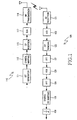
- FIG. 1 is a block diagram schematically illustrating the construction of a single-transmission antenna single-carrier frequency-domain equalization system.
- the single carrier-frequency domain equalization (SC-FDE) system includes a transmission device 110 and a reception device 120.
- the transmission device 110 includes a bit generator 111, a symbol mapping unit 113, a cyclic prefix (CP) insertion unit 115, a digital/analog (D/A) converter 117, and an RF transmission unit 119.
- the bit generator 111 generates information bits.
- the symbol mapping unit 113 maps a bit stream, which is output from the bit generator 111, to a symbol having a predetermined length.
- 'n' represents an additive white Gaussian noise (AWGN), the average of which is zero.
- Channel matrix "H” having a size of "NxN” is a circulant matrix, the first row of which is configured with a vector obtained by adding "N-L” number of "0" to a channel impulse response.
- a 2 X 1 SC system having two transmission antennas and one reception antenna is illustrated. Since the communication system according to the present invention processes a transmission sequence in a time band, it is impossible to intactly employ the SFBC having been used in an Orthogonal Frequency Division Multiplexing (OFDM) scheme. Therefore, in the communication system according to the present invention, a SC transmission sequence having the same effect as the SFBC is designed and used.
- OFDM Orthogonal Frequency Division Multiplexing
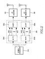
- FIG. 2 is a block diagram illustrating the conceptual construction of a transmission device of a communication system according to the present invention.
- symbols output from a symbol generator 210 are processed by a virtual signal processing unit 220, which includes a pair of Fourier transform units 221A and 221B and inverse Fourier transform units 222A and 222B corresponding to the Fourier transform units 221A and 221B, respectively, and then are output as two signal streams.
- Each signal stream is input to each corresponding CP insertion unit 231 or 232, which inserts a CP into each signal steam, and then is output through an antenna.
- the transmission device does not include the virtual signal processing unit which contains two Fourier transform units and two inverse Fourier transform units.
- the virtual signal processing unit which contains two Fourier transform units and two inverse Fourier transform units.
- Equations 5 and 6 a scaling factor of an inverse Fourier transmission is adjusted so as to enable the normal transmission power to be "1".
- the transmission symbol of a second antenna may be expressed as Equations 7 and 8, based on Equations 3 and 4. It can be understood from the second and third rows in Equation 7 that the SFBC is applied.
- Equation 8 the QPSK symbol is decomposed as shown in Equation 8.
- x e l x 2 ⁇ l
- x o l x ⁇ 2 ⁇ l + 1 herein
- l 0 , 1 , ⁇ , N / 2 ⁇ 1
- the output signals x 1 (0), x 1 (1), ..., and x 1 (N-1) of third multipliers 324 which are included in the operation modules 321-1, 321-2, ..., and 321-N of the operation unit 320, are output to a first CP insertion unit 231 as a first signal block, and the output signals x 2 (0), x 2 (1),..., and x 2 (N-1) of fourth multipliers 331 are output to a second CP insertion unit 232 as a second signal block.
- CPs are inserted into the first and second signal blocks by relevant CP insertion units 231 and 232, and the first and second signal blocks are output through first and second antennas, respectively.
- the CP is attached to the front end of each transmission block so as to lead a channel matrix to be a circulant matrix, and to remove inter-block interference (IBI).
- IBI inter-block interference
- the Fourier transform unit 405 performs n-point Fourier transformation with respect to parallel signals output from the serial to parallel converter 403, and the signal detector 407 detects a transmission signal from an output signal of the Fourier transform unit 405.
- the first demultiplexer 409 demultiplexes a signal detected by the signal detector 407.
- the complex conjugate transposer 411 performs a complex conjugate transpose operation with respect to odd-numbered frequency band detection signals of signals output from the first demultiplexer 409.
- the first inverse Fourier transform unit 413 performs N/2-point inverse Fourier transformation with respect to even-numbered frequency band detection signals of the signals output from the first demultiplexer 409.
- Equation 10 The signal of the frequency band obtained by Equation 10 is divided into even-numbered and odd-numbered frequency components as expressed in Equations 11 and 12, respectively.
- a received signal can be expressed as a linear combination of transmission signals by Equation 14, so signal detection can be performed based on minimum mean square error criterion.
- a finally-obtained equation is expressed in a similar form to that of a reception diversity system using maximal ratio combining (MRC), that is, as Equation 15.
- the presented operation amount has been obtained by calculating a mean value based on one block.
- the SC transmission scheme employing the SFBC technique has superior BER performance in comparison to other schemes employing the STBC technique.
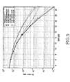
- a target BER is "10 -4 " in an EDGE TU channel
- the conventional STBC SC-FDE system is subjected to performance degradation of approximately 5 dB
- the SFBC SC-FDE system of the present invention is subjected to performance degradation of only approximately 0.7 dB.
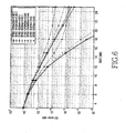
- the SC scheme provides superior performance to the OFDM scheme. If an adaptive bit loading or channel coding block is added to an OFDM system, the OFDM system has performance similar to the SC-FDE system.
Landscapes
- Engineering & Computer Science (AREA)
- Computer Networks & Wireless Communication (AREA)
- Signal Processing (AREA)
- Power Engineering (AREA)
- Mechanical Engineering (AREA)
- Radio Transmission System (AREA)
Description
- The present invention relates to Single Carrier-Frequency Domain Equalization (SC-FDE), and more particularly to a transceiving apparatus and method capable of compensating for a distortion phenomenon resulting from a fast fading environment, by applying a Space Frequency Block Coding (SFBC) technique to the SC-FDE technique.
- A frequency-domain equalization (FDE) technique is a technique for removing interference in a fading channel environment. Recently, an FDE-based single-carrier transmission scheme has been adopted as a standard for broadband wireless metropolitan area network (MAN) systems, such as an IEEE 802.16 system, an ETSI HiperMAN system, etc. An SC-FDE scheme has a similar construction and performance to an Orthogonal Frequency Division Multiplexing (OFDM) scheme, and is robust against non-linear distortion and carrier synchronization. In addition, the SC-FDE scheme can simplify the structure of a user terminal upon uplink communication by simply processing a signal in a transmission section.
- Meanwhile, studies and development are being conducted with respect to a transmission diversity technique, which can increase channel capacity and link reliability by spatially arranging a plurality of transmission antennas, without increasing a frequency bandwidth or transmission power. Recently, an SC-FDE technique, which employs a Space Time Bock Code (STBC) technique providing a transmission diversity gain, has been proposed. However, the STBC-based SC-FDE technique has a disadvantage in that this technique guarantees its performance only in a low-speed fading environment. Also, although the SFBC technique is more robust against a fading environment than the STBC technique, the SFBC technique has a technical problem, in that the SFBC technique cannot be directly applied to a single carrier system because it is a multi-carrier technique which applies a block code to a neighboring sub-channel or neighboring carrier.
- Accordingly, the present invention has been made to solve the above-mentioned problems occurring in the prior art.
-
US 6 834 043 B1 relates to achieving spatial diversity in a communication link having at least two transmitting antennas and at least one receive antenna. Symbols are encoded across the at least two transmitting antennas during a coding interval. Data is received at each receive antenna and at each symbol of the coding interval. Encoding strategies for embodiments with three or four transmitters in a single carrier system having cyclic prefixes are described. - It is the object of the present invention to provide a wireless communication system and method capable of compensating for any distortion phenomena caused in a fast fading environment and improving system performance while simplifying the construction of a transmitter, by employing single carrier-frequency domain equalization (SC-FDE) based on space frequency block coding (SFBC).
- This object is solved by the subject matter of the independent claims.
- Preferred embodiments are defined in the dependent claims.
- To accomplish this object, in accordance with one aspect of the present invention, there is provided a method for transmitting data in a communication system, which includes a transmission device and a reception device, in which the transmission device transmits a signal through at least two transmission antennas, and the reception device receives a signal through at least one reception antenna, the method including: encoding an input signal into frequency-domain blocks, and outputting at least two signal blocks in parallel to each other; and inserting a cyclic prefix (CP) into the output signal blocks, and outputting the signal blocks through each corresponding antenna by loading the signal blocks on a single carrier. Preferably, the step of outputting at least two signal blocks in parallel to each other further includes: demultiplexing N number of input signals to separate the input signals into even-numbered transmission samples and odd-numbered transmission samples, which have a period of N/2; shifting a phase of the odd-numbered transmission sample and adding the even-numbered transmission sample to the phase-shifted odd-numbered transmission sample, thereby generating a first signal block; performing a complex conjugate operation, phase shift, and transposition with respect to the even-numbered and odd-numbered transmission samples by applying the symmetric characteristic of a Fourier transformation to a frequency-domain block code, thereby generating a second signal block.
- In accordance with another aspect of the present invention, there is provided a method for receiving data in a communication system, which includes a transmission device and a reception device, in which the transmission device transmits a signal through at least two transmission antennas, and the reception device receives a signal through at least one reception antenna, the method including: receiving signals output from at least two different transmission antennas through a single carrier by means of one reception antenna; removing a CP from the received signal; performing a serial to parallel conversion operation with respect to the CP-removed signal; performing Fourier transformation with respect to the parallel signals; detecting even-numbered frequency components and odd-numbed frequency components from the Fourier-transformed signal; performing a complex conjugate operation with respect to the odd-numbered frequency components, and combining the odd-numbered frequency components by a linear combiner; detecting a frequency component estimation value for a transmission signal from the linearly-combined frequency components based on a mean square error criterion through a channel equalizer; demultiplexing the detected frequency components; performing an N/2-point inverse Fourier transformation with respect to even-numbered frequency components of the demultiplexed frequency components; performing a complex conjugate operation with respect to odd-numbered frequency components of the demultiplexed frequency components; performing an N/2-point inverse Fourier transformation with respect to signals which have been subjected to the complex conjugate operation; and multiplexing N signals, which are output after being subjected to the inverse Fourier transformation, thereby restoring original data.
- In accordance with still another aspect of the present invention, there is provided a communication system which includes a transmission device for transmitting a signal through at least two transmission antennas; and a reception device for receiving a signal through at least one reception antenna, wherein the transmission device includes a symbol mapping unit for mapping input information bits to symbols; a demultiplexer for demultiplexing the symbols output from the symbol mapping unit; a symbol processing unit for processing parallel symbols output from the demultiplexer, thereby outputting at least two signal blocks as frequency-domain blocks in parallel to each other; and a cyclic prefix (CP) insertion unit for inserting a CP into the signal blocks output in parallel from the symbol processing unit, and then transmitting the signal blocks.
- In accordance with still another aspect of the present invention, there is provided a communication system which includes a transmission device for transmitting a signal through at least two transmission antennas; and a reception device for receiving a signal through at least one reception antenna, wherein the reception device includes a cyclic prefix (CP) removing unit for removing a CP from a received signal; a serial to parallel converter for performing serial to parallel conversion with respect to a signal, from which a CP is removed by the CP removing unit; a Fourier transform unit for performing Fourier transformation with respect to signals output in parallel from the serial to parallel converter; a signal combiner and a channel equalization signal detector for combining frequency-domain-blocked signals output from the Fourier transform unit, based on a minimum mean square error criterion; a demultiplexer for demultiplexing the frequency-band signals detected by the signal detector; a first inverse Fourier transform unit for performing inverse Fourier transformation with respect to an even-numbered frequency sub-channel of signals output from the demultiplexer; a complex conjugate operator for performing a complex conjugate operation with respect to an odd-numbered frequency component of signals output from the demultiplexer; a second inverse Fourier transform unit for performing inverse Fourier transformation with respect to an output signal of the complex conjugate operator; and a multiplexer for multiplexing output signals of the first and second inverse Fourier transform units, thereby restoring original data.
- The present invention will be more apparent from the following detailed description taken in conjunction with the accompanying drawings, in which:
-
FIG. 1 is a block diagram schematically illustrating the construction of a single-transmission antenna single-carrier frequency-domain equalization system; -
FIG. 2 is a block diagram illustrating the conceptual construction of a transmission device of a communication system according to an embodiment of the present invention; -
FIG. 3 is a block diagram illustrating the construction of a signal processing unit, which is substituted for the virtual signal processing unit shown inFIG. 2 , according to an embodiment of the present invention; -
FIG. 4 is a block diagram illustrating the construction of a reception device of a communication system according to an embodiment of the present invention; -
FIG. 5 is a graph illustrating a result of a performance comparison test between the SFBC SC-FDE-based communication system of the present invention and the conventional (STBC) SC-FDE-based communication system; and -
FIG 6 is a graph illustrating a result of a performance test between OFDM systems and SC systems, to each of which STBC and SFBC transmission diversity techniques are selectively applied. - Hereinafter, a preferred embodiment of a transceiving apparatus and method - based on the space frequency block coding (SFBC) and single carrier-frequency domain equalization (SC-FDE) - according to the present invention will be described with reference to the accompanying drawings. In the following description of the embodiments of the present invention, a detailed description of known functions and configurations incorporated herein will be omitted when it may obscure the subject matter of the present invention.
-
FIG. 1 is a block diagram schematically illustrating the construction of a single-transmission antenna single-carrier frequency-domain equalization system. The single carrier-frequency domain equalization (SC-FDE) system includes atransmission device 110 and areception device 120. Thetransmission device 110 includes abit generator 111, asymbol mapping unit 113, a cyclic prefix (CP)insertion unit 115, a digital/analog (D/A)converter 117, and anRF transmission unit 119. Thebit generator 111 generates information bits. Thesymbol mapping unit 113 maps a bit stream, which is output from thebit generator 111, to a symbol having a predetermined length. TheCP insertion unit 115 inserts a cyclic prefix (CP) into the symbol output from thesymbol mapping unit 113, and the D/A converter 117 converts a digital signal output from theCP insertion unit 115 into an analog signal. TheRF transmission unit 119 transmits the analog signal, which is output from the D/A converter 117, via a radio frequency. - The
reception device 120 includes anRF reception unit 121, an analog/digital (A/D)converter 123, aCP removing unit 125, a Fouriertransform unit 127, afrequency domain equalizer 129, an inverse Fouriertransform unit 124, a symbol de-mappingunit 126, and asignal determination unit 128. TheRF reception unit 121 receives a signal through a wireless channel. The A/D converter 123 converts an analog signal, which has been output from theRF reception unit 121, into a digital signal. TheCP removing unit 125 removes a CP from a digital signal output from the A/D converter 123, and the Fouriertransform unit 127 performs a Fourier transformation of a signal output from theCP removing unit 125. Thefrequency domain equalizer 129 performs an equalization of a signal output from the Fouriertransform unit 127, and the inverse Fouriertransform unit 124 performs inverse Fourier transformation of a signal output from thefrequency domain equalizer 129. The symbol de-mappingunit 126 converts a symbol output from the inverse Fouriertransform unit 124 into a bit stream, and outputs the converted bit stream. Thesignal determination unit 128 determines a transmission signal in consideration of the bit stream output from thesymbol de-mapping unit 126. - In the communication system using a single-carrier scheme, as shown in
FIG. 1 , a CP has a length identical to that of a channel impulse response (CIR) modeled by an L-order frequency impulse response (FIR) filter. When it is assumed that a transmitted symbol vector is "x" in a block having a length of "N", a received symbol vector may be expressed asEquation 1.
- Herein, 'n' represents an additive white Gaussian noise (AWGN), the average of which is zero. Channel matrix "H" having a size of "NxN" is a circulant matrix, the first row of which is configured with a vector obtained by adding "N-L" number of "0" to a channel impulse response. The channel matrix "H" is decomposed as shown in
Equation 2.
- Herein, "W" represents an orthonormal Fourier transformation matrix (WHW = WWH = IN) having a size of "NxN", "(·)H" represents a complex conjugate transpose, and "Λ" represents a diagonal matrix having Fourier transformation values of a channel impulse response.
- According to the present invention, a 2X 1 SC system having two transmission antennas and one reception antenna is illustrated. Since the communication system according to the present invention processes a transmission sequence in a time band, it is impossible to intactly employ the SFBC having been used in an Orthogonal Frequency Division Multiplexing (OFDM) scheme. Therefore, in the communication system according to the present invention, a SC transmission sequence having the same effect as the SFBC is designed and used.
-
FIG. 2 is a block diagram illustrating the conceptual construction of a transmission device of a communication system according to the present invention. When considering symbol transmission in a time band, rather than a frequency band, symbols output from asymbol generator 210 are processed by a virtualsignal processing unit 220, which includes a pair of Fouriertransform units Fourier transform units CP insertion unit signal processing unit 220 shown inFIG. 2 is only a virtual element for illustrating a conception of generating a single-carrier transmission signal in a time band to which the SFBC is applied. That is, the transmission device according to the present invention does not include the virtual signal processing unit which contains two Fourier transform units and two inverse Fourier transform units. When block codes are applied with respect to two neighboring frequency sub-channels and two transmission antennas at the rear ends of theFourier transform units symbol generator 210 based on the symmetric characteristic of the Fourier transformation as expressed inEquation 3.
- When an nth symbol of a block transmitted from an ith antenna is expressed as xi (n), a transmission symbol of a first antenna may be expressed as
Equation 4.
- Herein, xe(n) and x0(n) are defined as
Equations 5 and 6, respectively.

- Since xe(n) and x o(n) have a period of N/2 as a function of 'n', xe(n) and xo (n) can be replaced with


- In
Equations 5 and 6, a scaling factor of an inverse Fourier transmission is adjusted so as to enable the normal transmission power to be "1". The transmission symbol of a second antenna may be expressed asEquations 7 and 8, based onEquations 
-
F1G 3 is a block diagram illustrating the construction of a signal processing unit, which is substituted for the virtual signal processing unit shown inFIG. 2 , according to the present invention. When an actual transmission device is manufactured, the virtual signal processing unit is replaced with the signal processing unit shown inFIG 3 . - As shown in
FIG 3 , the signal processing unit includes ademultiplexer 310 for demultiplexing symbols input from thesymbol generator 210, and anoperation unit 320 for processing signals output in parallel from thedemultiplexer 3 10 and outputting the processed signals as a signal block. - In the case of QPSK symbols, the QPSK symbol is decomposed as shown in
Equation 8.
- Referring to
FIG. 3 , thedemultiplexer 310outputs 0 to (N-1)th signals in parallel with a period of "N/2". Each signal input to thedemultiplexer 310 is output as a pair of odd/even signals and then is input to theoperation unit 320. Theoperation unit 320 includes N number of operation modules 321-1 to 321-N for processing each signal. - Each operation module includes a
first multiplier 323, asecond multiplier 327, afirst adder 322, asecond adder 329, athird multiplier 324, and afourth multiplier 331. Thefirst multiplier 323 multiplies an odd signal of relevant input signals by a phase shift coefficient. Thesecond multiplier 327 multiplies an output signal of acomplex conjugate transposer 325, which performs a complex conjugate transpose operation with respect to the odd and even signals, by the same phase shift coefficient as that used in thefirst multiplier 323. Thefirst adder 322 adds an output signal of thefirst multiplier 323 and the even signal. Thesecond adder 329 adds an output signal of thecomplex conjugate transposer 325 and an output signal of thesecond multiplier 327. Thethird multiplier 324 multiplies an output signal of thefirst adder 322 by a normalization factor, and thefourth multiplier 331 multiplies an output signal of thesecond adder 329 by the normalization factor. - The output signals x1(0), x1(1), ..., and x1(N-1) of
third multipliers 324, which are included in the operation modules 321-1, 321-2, ..., and 321-N of theoperation unit 320, are output to a firstCP insertion unit 231 as a first signal block, and the output signals x2(0), x2(1),..., and x2(N-1) offourth multipliers 331 are output to a secondCP insertion unit 232 as a second signal block. CPs are inserted into the first and second signal blocks by relevantCP insertion units -
FIG. 4 is a block diagram illustrating the construction of a reception device of a communication system according to the present invention. The reception device shown inFIG. 4 has a construction corresponding to the virtual transmission device ofFIG. 2 or the actually-realized transmission device ofFIG. 3 . - The reception device includes a
CP removing unit 401, a serial toparallel converter 403, aFourier transform unit 405, asignal detector 407, afirst demultiplexer 409, acomplex conjugate transposer 411, a first inverseFourier transform unit 413, a second inverseFourier transform unit 415, and amultiplexer 417. TheCP removing unit 401 removes a CP from a signal received through an antenna, and the serial toparallel converter 403 performs serial to parallel conversion with respect to an output signal of theCP removing unit 401. TheFourier transform unit 405 performs n-point Fourier transformation with respect to parallel signals output from the serial toparallel converter 403, and thesignal detector 407 detects a transmission signal from an output signal of theFourier transform unit 405. Thefirst demultiplexer 409 demultiplexes a signal detected by thesignal detector 407. Thecomplex conjugate transposer 411 performs a complex conjugate transpose operation with respect to odd-numbered frequency band detection signals of signals output from thefirst demultiplexer 409. The first inverseFourier transform unit 413 performs N/2-point inverse Fourier transformation with respect to even-numbered frequency band detection signals of the signals output from thefirst demultiplexer 409. The second inverseFourier transform unit 415 performs N/2-point inverse Fourier transformation with respect to an output signal of thecomplex conjugate transposer 411. Themultiplexer 417 multiplexes the output signals of the first and second inverseFourier transform unit signal detector 407 includes alinear combiner 406 for combining output signals of theFourier transform unit 405, and a single-carrierfrequency domain equalizer 408 for performing frequency domain equalization with respect to an output signal of thelinear combiner 406. - The
linear combiner 406 of thesignal detector 407 detects a signal by using a combining scheme based on minimum mean square error estimation, and a signal detected thereby may be expressed as Equation 9.
- Herein, "H1" and "H2" represent channel matrixes of first and second transmission antennas, respectively. A signal of a frequency band obtained by multiplying the "r" by a Fourier transform matrix "W" is expressed as
Equation 10.
- The signal of the frequency band obtained by
Equation 10 is divided into even-numbered and odd-numbered frequency components as expressed inEquations 11 and 12, respectively.

- When the complex conjugate of the odd-numbered frequency components "R(2m+1)", the following Equation 13 can be obtained.

- When it is assumed that channel information about two adjacent frequency bands is constant, that is, when it is assumed that Λ1, (2m)≈Λ1 (2m + 1) and Λ2(2m)≈Λ2(2m + 1), Equations 11 and 13 may be expressed as a matrix equation of
Equation 14.
- A received signal can be expressed as a linear combination of transmission signals by
Equation 14, so signal detection can be performed based on minimum mean square error criterion. A finally-obtained equation is expressed in a similar form to that of a reception diversity system using maximal ratio combining (MRC), that is, as Equation 15.
- It must be considered that determination values are obtained in a time domain although channel equalization is performed in a frequency domain. Therefore, an estimation value of a transmission symbol is expressed as the following
Equation 16.
- When the communication system according to the present invention is compared with the conventional systems (such as an STBC-OFDM, an SFBC-OFEM, and STBC-FDE systems), in view of system complexity, it can be summarized as shown in Table 1.
Table 1 Classification Number of Complex Multiplication STBC (SFBC) OFDM (N/2)(3log2 N+6) STBC SC-FDE N(log2 N+3) SFBC SC-FDE (N/2)(2log2 N+9) - The presented operation amount has been obtained by calculating a mean value based on one block. Compared with the STBC or SFBC system, in view of relative complexity, the communication system of the present invention provides a calculation-amount reduction effect of 12.5% or 18.2% when N=16 or N=512, respectively. Also, compared with the STBC SC-FDE, it can be understood that the communication system of the present invention requires equation amount incremented by approximately 16.7% or 11.5% when N=16 or N=512, respectively.
- Hereinafter, the result of a performance test for the communication system according to the present invention will be described with reference to the accompanying graphs.
- In this test, each bit error rate (BER) is measured with respect to four types of
2x 1 antenna systems, that is, with respect to the STBC-OFDM, SFBC-OFDM, and STBC-FDE systems, and the SFBC SC-FDE system according to the present invention. Herein, it is assumed that each reception device has precise information about channel states, and an SC system has an ideal pulse form capable of being perfectly reconstructed. In addition, a CP is set to have a length equal to the order of a channel, and the equalizer of each reception device is set to follow the minimum mean square error criterion. -
FIG. 5 is a graph illustrating a result of a performance comparison test between the SFBC SC-FDE-based communication system of the present invention and the conventional STBC SC-FDE-based communication system, with respect to a quasistatic (normalized Doppler frequency fdts=0.001) and fast fading channel. This test is performed by using a typical urban (TU) channel for an EDGE (Enhanced Data rates for GSM Evolution) scheme, having been proposed as the third-generation TDMA (Time Division Multiple Access) cellular standard.FIG. 6 is a graph illustrating a result of a performance test between OFDM systems and SC systems, to each of which STBC and SFBC transmission diversity techniques are selectively applied. A COST 207 6 tap TU channel used in this test has a root mean square (RMS) delay spread of approximately 2.3 µs, and has been known as a channel having a superior frequency-selective property. As this test is intended to compare performance degradation in a fast fading channel environment, 512-point fast Fourier transformation is performed in order to minimize an influence of the frequency-selective property. - Referring to
FIGs. 5 and6 , in the case of a channel having a large Doppler spread, it can be understood that the SC transmission scheme employing the SFBC technique has superior BER performance in comparison to other schemes employing the STBC technique. For example, when a target BER is "10-4" in an EDGE TU channel, the conventional STBC SC-FDE system is subjected to performance degradation of approximately 5 dB, while the SFBC SC-FDE system of the present invention is subjected to performance degradation of only approximately 0.7 dB. Also, as shown inFIG. 6 , in the case of transmission of an uncoded signal, it can be understood that the SC scheme provides superior performance to the OFDM scheme. If an adaptive bit loading or channel coding block is added to an OFDM system, the OFDM system has performance similar to the SC-FDE system. - As described above, when employing an SC-FDE system to which an SFBC is applied, the communication system of the present invention has obtained the advantages of both the SFBC and the SC-FDE system. That is, the communication system of the present invention is robust against a non-linear distortion or carrier synchronization error, and can minimize performance degradation even in a fast fading environment while having a transmission diversity gain. In addition, the SFBC-based SC-FDE system of the present invention has another advantage in that it can be easily applied to general multiple input multiple output antenna systems.
- While the present invention has been shown and described with reference to certain preferred embodiments thereof, it will be understood by those skilled in the art that various changes in form and details may be made therein without departing from the scope of the invention as defined by the appended claims. Accordingly, the scope of the invention is not to be limited by the above embodiments but by the claims.
Claims (5)
- A method for transmitting data in a communication system, the method comprising the steps of: encoding an input signal into frequency-domain blocks, and outputting at least two signal blocks in parallel to each other comprising demultiplexing N number of input samples to separate the input samples into a vector of even-numbered transmission samples and a vector of odd-numbered transmission samples, which have a period of N/2 and a length of N, and generating a first signal block and a second signal block by using the vectors of even-numbered and odd-numbered transmission samples; inserting a cyclic prefix, CP, into the output signal blocks, and outputting the signal blocks through each corresponding antenna by loading the signal blocks on a single carrier,
wherein the step of generating the first signal block comprises generating a first phase-shifted vector by multiplying the odd-numbered transmission sample by a vector of phase shift coefficients which increment exponentially with the position of the phase shift coefficient within the vector;
generating a first accumulation vector by adding the first phase-shifted vector and the vector of even-numbered transmission samples; and
generating the first signal block by multiplying the first accumulation vector by a normalization coefficient;
wherein the step of generating the second signal block comprises
performing a change of sign operation, a complex conjugate operation and a time reversal operation with respect to the vector of odd-numbered transmission samples, thereby generating a vector of sign inverted, complex conjugated, time reversed odd-numbered transmission samples;
performing a complex conjugate operation and a time reversal operation with respect to the vector of even-numbered transmission samples, thereby generating a vector of complex conjugated, time reversed even-numbered transmission samples;
generating a second phase-shifted vector by multiplying the vector of complex conjugated, time reversed even-numbered transmission samples by said vector of phase shift coefficients which increment exponentially with the position of the phase shift coefficient within the vector;
generating a second accumulation vector by adding the second phase-shifted vector and the vector of sign inverted, complex conjugated, time reversed odd-numbered transmission samples; and
generating the second signal block by multiplying the second accumulation vector by said normalization coefficient. - A method for receiving data in a communication system, the method comprising the steps of:receiving signals output from at least two different transmission antennas through a single carrier by means of one reception antenna;removing a cyclic prefix, CP, from the received signal;performing a serial to parallel conversion operation with respect to the CP-removed signal;performing Fourier transformation with respect to the parallel signals;wherein for each pair of adjacent frequency components of the Fourier transformed signal consisting of an even-numbered and an odd-numbered frequency componentwherein- the conjugate of the odd-numbered frequency component is calculated and a column vector
 - the product between the hermitian of the matrix Λm' with Rm' is calculated to obtain a linear combination of the adjacent frequency components,
performing frequency domain equalization with respect to said linear combination of the adjacent frequency components, thus obtaining frequency domain equalized linear combined even-numbered and odd-numbered frequency components ;
performing a first inverse Fourier transformation with respect to the frequency domain equalized linear combined even-numbered frequency components thereby obtaining time-domain even samples;
performing a complex conjugate operation with respect to the frequency domain equalized linear combined odd-numbered frequency components;
performing a second inverse Fourier transformation with respect to the frequency components having been subjected to the complex conjugate operation, thereby obtaining time-domain odd samples; and
multiplexing the time-domain even samples with the time-domain odd samples, thereby estimating the transmission symbols. - The method as claimed in claim 2, further comprising
linearly-combining the Fourier-transformed frequency components based on a minimum mean square error criterion. - An apparatus for transmitting data in a communication system, the apparatus comprising:a demultiplexer (310) for demultiplexing N number of input samples to separate the input samples into a vector of even-numbered transmission samples and a vector of odd-numbered transmission samples, which have a period of N/2 and a length of N;an encoder (320) for generating a first signal block and a second signal block in parallel to each other by using the vectors of even-numbered and odd-numbered transmission samples;a cyclic prefix insertion unit (231, 232) inserting a cyclic prefix into the generated signal blocks; andan output unit for outputting the generated signal blocks having a cyclic prefix through each corresponding antenna by loading the signal blocks on a single carrier,wherein the encoder comprises N number of signal processing modules (321-1, 321-2, 321-N) for processing the samples of the vectors of even-numbered and odd-numbered transmission samples,each of the signal processing modules comprising:a first multiplier (323) for multiplying an odd-numbered transmission sample by a phase shift coefficient which increments exponentially with the position of the sample within the vector, thereby generating a first phase-shifted signal;a first adder (322) for adding the first phase-shifted signal and the corresponding even-numbered transmission sample, thereby generating a first accumulation sample;a second multiplier (324) for multiplying the first accumulation sample by a normalization coefficient, thereby generating a first normalized sample;a complex conjugate module (325) for performing a complex conjugate and a time reversal operation with respect to an even-numbered and a change of sign, complex conjugate and a time reversal operation with respect to the corresponding odd-numbered transmission samples, thereby generating a complex conjugate even-numbered and complex conjugate odd-numbered transmission sample;a third multiplier (327) for multiplying the complex conjugate even-numbered transmission sample by a phase shift coefficient which increments exponentially with the position of the sample within the vector, thereby generating a second phase-shifted sample;a second adder (329) for adding the second phase-shifted sample and the complex conjugate odd-numbered transmission sample, thereby generating a second accumulation sample; anda fourth multiplier (331) for multiplying the second accumulation sample by the normalization coefficient, thereby generating a second normalized sample,wherein the first signal block is generated by the vector of first normalized samples, and wherein the second signal block is generated by the vector of second normalized samples.
- An apparatus for receiving data in a communication system, the apparatus comprising:at least one reception antenna for receiving signals output from at least two different transmission antennas through a single carrier;a cyclic prefix, CP, removing unit (401) for removing a CP from the received signal;a serial to parallel converter (403) for performing serial/parallel conversion with respect to the CP removed signal;a Fourier transform unit (405) for performing Fourier transformation with respect to signals output in parallel from the serial to parallel converter;a linear combiner (406) for combining the adjacent output signals of the Fourier transform unit (405) based on a minimum mean square error criterion, said linear combiner comprising means for calculating, for each pair of adjacent frequency components of the Fourier transformed signal consisting of an even-numbered and an odd-numbered frequency component, the product between the hermitian of the matrix Λ'm with R'm, wherein

 a single-carrier frequency domain equalizer (408) for performing frequency domain equalization with respect to an output signal of the linear combiner (406);a demultiplexer (409) for demultiplexing the frequency domain equalized linearly combined frequency components;a first inverse Fourier transform unit (413) for performing inverse Fourier transformation with respect to the frequency domain equalized linearly combined even-numbered frequency components output from the demultiplexer;a complex conjugate operator (411) for performing a complex conjugate operation with respect to the frequency domain equalized linearly combined odd-numbered frequency components output from the demultiplexer;a second inverse Fourier transform unit (415) for performing inverse Fourier transformation with respect to an output signal of the complex conjugate operator;a multiplexer (417) for multiplexing output signals of the first and second inverse Fourier transform units, thereby estimating the transmission symbols.
Applications Claiming Priority (1)
| Application Number | Priority Date | Filing Date | Title |
|---|---|---|---|
| KR1020050024137A KR100950639B1 (en) | 2005-03-23 | 2005-03-23 | Transmission and reception apparatus and method using frequency space block coding technique and single carrier frequency domain equalization |
Publications (2)
| Publication Number | Publication Date |
|---|---|
| EP1705823A1 EP1705823A1 (en) | 2006-09-27 |
| EP1705823B1 true EP1705823B1 (en) | 2008-10-01 |
Family
ID=36218178
Family Applications (1)
| Application Number | Title | Priority Date | Filing Date |
|---|---|---|---|
| EP06006043A Expired - Lifetime EP1705823B1 (en) | 2005-03-23 | 2006-03-23 | Transceiving apparatus and method using space-frequency block-coded single-carrier frequency domain equalization |
Country Status (5)
| Country | Link |
|---|---|
| US (1) | US7680200B2 (en) |
| EP (1) | EP1705823B1 (en) |
| KR (1) | KR100950639B1 (en) |
| CN (1) | CN1838581B (en) |
| DE (1) | DE602006002905D1 (en) |
Families Citing this family (27)
| Publication number | Priority date | Publication date | Assignee | Title |
|---|---|---|---|---|
| JP4707071B2 (en) * | 2004-08-03 | 2011-06-22 | エージェンシー フォー サイエンス, テクノロジー アンド リサーチ | Signal detection method, detector and computer program product |
| JP4249167B2 (en) * | 2005-08-29 | 2009-04-02 | ジーイー・メディカル・システムズ・グローバル・テクノロジー・カンパニー・エルエルシー | AD conversion circuit with carrier frequency elimination function |
| KR100981495B1 (en) * | 2005-10-12 | 2010-09-10 | 삼성전자주식회사 | Method and apparatus for data transmission in communication system |
| WO2008066349A1 (en) | 2006-12-01 | 2008-06-05 | Electronics And Telecommunications Research Institute | Method and apparatus for transmitting/receiving multiple codewords in sc-fdma system |
| KR100874264B1 (en) | 2006-12-01 | 2008-12-16 | 한국전자통신연구원 | Method and apparatus for multiple code word transmission / reception in SC-FDMA system |
| US8130846B2 (en) * | 2006-12-11 | 2012-03-06 | New Jersey Institute Of Technology | System and method for single-carrier space-frequency block coded transmission over frequency selective and fast fading channels |
| KR100787179B1 (en) * | 2006-12-26 | 2007-12-21 | (주)카이로넷 | Cell searching device and method in wireless communication system |
| KR100969771B1 (en) | 2007-01-31 | 2010-07-13 | 삼성전자주식회사 | Signal transceiving device and method in communication system |
| KR100816032B1 (en) | 2007-02-13 | 2008-03-24 | 삼성전자주식회사 | Method and apparatus for data transmission and reception through repetitive multi-user detection |
| JP5284284B2 (en) * | 2007-02-15 | 2013-09-11 | ミツビシ・エレクトリック・アールアンドディー・センター・ヨーロッパ・ビーヴィ | SC-QOSTFBC code for MIMO transmitter |
| EP1976173A1 (en) * | 2007-03-30 | 2008-10-01 | Mitsubishi Electric Information Technology Centre Europe B.V. | Method of multi-antenna wireless data emission, emitter and receiver using the method |
| EP1959603A1 (en) * | 2007-02-15 | 2008-08-20 | Mitsubishi Electric Information Technology Center Europe B.V. | Method of radio data emission, emitter and receiver using the method |
| CN101359982B (en) * | 2007-08-03 | 2012-10-17 | 华为技术有限公司 | Space frequency group code detection method and apparatus |
| KR101365565B1 (en) | 2007-08-08 | 2014-02-21 | 포항공과대학교 산학협력단 | Space frequency block code signal processing system |
| KR101329145B1 (en) | 2007-10-05 | 2013-11-21 | 포항공과대학교 산학협력단 | Method of space block coding signal transmission and receive with interactive multiuser detection, and aparatus using the same |
| CN101197796B (en) * | 2007-10-23 | 2010-11-03 | 中国科学院嘉兴无线传感网工程中心 | Wireless sensor network channel evaluation method based on SC-FDE and virtual multi-antenna |
| KR100936242B1 (en) * | 2007-10-29 | 2010-01-12 | 전자부품연구원 | FFT / IFFT dual mode device and control method thereof for OPDM |
| KR101008070B1 (en) * | 2008-11-19 | 2011-01-13 | 포항공과대학교 산학협력단 | Frequency domain equalization method and apparatus |
| WO2010077104A2 (en) * | 2008-12-31 | 2010-07-08 | 포스데이타 주식회사 | Transmission device and method using space-frequency transmission diversity |
| KR101547284B1 (en) | 2008-12-31 | 2015-08-25 | 인텔렉추얼디스커버리 주식회사 | Transmitting apparatus and method using space-frequency transmit diversity |
| CN101826944B (en) * | 2009-03-03 | 2014-12-10 | 中兴通讯股份有限公司 | Method and device for multi-node cooperative transmission |
| KR101026021B1 (en) * | 2009-09-16 | 2011-03-30 | 포항공과대학교 산학협력단 | Method and apparatus for detecting space-time block codes |
| US8687726B2 (en) * | 2009-11-09 | 2014-04-01 | Time Reversal Communications | Method for transmitting digital data, and transmitter base implementing such a method |
| CN102148634B (en) * | 2010-02-08 | 2013-12-25 | 电信科学技术研究院 | Antenna transmit diversity method and system |
| US8630357B2 (en) * | 2011-02-07 | 2014-01-14 | ABG Tag & Traq, LLC | Ultra-wideband dual band magnitude summer apparatus and method |
| CN102437906B (en) * | 2012-01-20 | 2013-12-04 | 中国科学院上海微系统与信息技术研究所 | Design method of HARQ (Hybrid Automatic Repeat-request) communication way applied to SC-FDE (Signal Carrier Frequency-Domain Equalization) baseband system |
| US9755722B2 (en) | 2014-08-07 | 2017-09-05 | Mitsubishi Electric Corporation | Transmission device, reception device, communication system, transmission method and reception method |
Family Cites Families (10)
| Publication number | Priority date | Publication date | Assignee | Title |
|---|---|---|---|---|
| CA2302289C (en) | 1996-08-29 | 2005-11-08 | Gregory G. Raleigh | Spatio-temporal processing for communication |
| US6377632B1 (en) * | 2000-01-24 | 2002-04-23 | Iospan Wireless, Inc. | Wireless communication system and method using stochastic space-time/frequency division multiplexing |
| US7068628B2 (en) * | 2000-05-22 | 2006-06-27 | At&T Corp. | MIMO OFDM system |
| US6834043B1 (en) | 2000-07-24 | 2004-12-21 | Motorola, Inc. | Method and device for exploiting transmit diversity in time varying wireless communication systems |
| US6999508B1 (en) * | 2000-11-07 | 2006-02-14 | Texas Instruments Incorporated | Multi-channel frequency domain equalizer for radio frequency interference cancellation |
| EP1435172A4 (en) * | 2001-09-12 | 2009-11-11 | Samsung Electronics Co Ltd | METHOD AND APPARATUS FOR TRANSFERRING CHANNEL INFORMATION IN ORTHOGONAL FREQUENCY DIVISION MULTIPLEXING (OFDM) COMMUNICATIONS |
| US6912195B2 (en) | 2001-12-28 | 2005-06-28 | Motorola, Inc. | Frequency-domain MIMO processing method and system |
| US7280604B2 (en) * | 2002-04-22 | 2007-10-09 | Regents Of The University Of Minnesota | Space-time doppler coding schemes for time-selective wireless communication channels |
| GB2393618B (en) * | 2002-09-26 | 2004-12-15 | Toshiba Res Europ Ltd | Transmission signals methods and apparatus |
| US8040968B2 (en) * | 2004-09-30 | 2011-10-18 | Intel Corporation | High rate, high diversity transmission on multiple transmit antennas |
-
2005
- 2005-03-23 KR KR1020050024137A patent/KR100950639B1/en not_active Expired - Lifetime
-
2006
- 2006-03-23 CN CN2006100680034A patent/CN1838581B/en not_active Expired - Lifetime
- 2006-03-23 DE DE602006002905T patent/DE602006002905D1/en not_active Expired - Lifetime
- 2006-03-23 EP EP06006043A patent/EP1705823B1/en not_active Expired - Lifetime
- 2006-03-23 US US11/387,415 patent/US7680200B2/en active Active
Also Published As
| Publication number | Publication date |
|---|---|
| US7680200B2 (en) | 2010-03-16 |
| KR20060102185A (en) | 2006-09-27 |
| EP1705823A1 (en) | 2006-09-27 |
| CN1838581B (en) | 2010-11-03 |
| KR100950639B1 (en) | 2010-04-01 |
| CN1838581A (en) | 2006-09-27 |
| DE602006002905D1 (en) | 2008-11-13 |
| US20060215541A1 (en) | 2006-09-28 |
Similar Documents
| Publication | Publication Date | Title |
|---|---|---|
| EP1705823A1 (en) | Transceiving apparatus and method using space-frequency block-coded single-carrier frequency domain equalization | |
| US8275053B2 (en) | Apparatus and method of estimating channel based on channel delay spread in mobile communication system | |
| EP3437197B1 (en) | Tomlinson-harashima precoding in an otfs communication system | |
| AU2007233563B2 (en) | Channel estimation for rapid dispersive fading channels | |
| US8351553B2 (en) | MIMO receiving apparatus and receiving method | |
| US8290081B2 (en) | Transmission/reception methods and modules for a multiple-carrier multiple-antenna system using training sequences | |
| CN101471912B (en) | Transmitting device, transmitting/receiving device, transmitting method and transmitting/receiving method | |
| CN101682454B (en) | Method for transmitting and receiving a multicarrier spread-spectrum signal and corresponding signal, and transmission and reception devices | |
| WO2005022815A1 (en) | Ofdm channel estimation and tracking for multiple transmit antenna | |
| US7945005B2 (en) | Method and module for estimating transmission chanels of a multi-antenna multi-carrier system | |
| EP2701355B1 (en) | Method and apparatus for transmitting/receiving a signal in an ffh-ofdm communication system | |
| EP1776818B1 (en) | Method for equalizing a digital signal and equalizer | |
| EP2023518A1 (en) | Receiver and receiving method | |
| US7929413B2 (en) | Transmission system, transmission method, transmitter, receiver, decoding method, and decoder | |
| WO2008020504A1 (en) | Wireless transmission method using ofdm and transmitter and receiver thereof | |
| EP1804410B1 (en) | Apparatus and method for transmitting and receiving a signal in a wireless communcation system | |
| US7619964B2 (en) | High doppler channel estimation for OFD multiple antenna systems | |
| US11108600B2 (en) | Systems and methods for time domain layer separation in orthogonal frequency division multiplexing-based receivers | |
| US7912146B2 (en) | Method and apparatus for transmitting data in a communication system | |
| KR100975722B1 (en) | Method and system for transmitting and receiving data in communication system | |
| US7333538B2 (en) | Equalisation method and device of the GMMSE type | |
| CN101848178A (en) | Single carrier frequency domain equalization method and system as well as sending and receiving device | |
| CN101335551B (en) | SINR estimation method based on multi-antenna diversity scheme of DFT-S-GMC system | |
| EP2003833A1 (en) | Method of equalizing a multicarrier signal for intercarrier interference | |
| JP6209087B2 (en) | Receiving apparatus and program |
Legal Events
| Date | Code | Title | Description |
|---|---|---|---|
| PUAI | Public reference made under article 153(3) epc to a published international application that has entered the european phase |
Free format text: ORIGINAL CODE: 0009012 |
|
| 17P | Request for examination filed |
Effective date: 20060323 |
|
| AK | Designated contracting states |
Kind code of ref document: A1 Designated state(s): AT BE BG CH CY CZ DE DK EE ES FI FR GB GR HU IE IS IT LI LT LU LV MC NL PL PT RO SE SI SK TR |
|
| AX | Request for extension of the european patent |
Extension state: AL BA HR MK YU |
|
| RAP1 | Party data changed (applicant data changed or rights of an application transferred) |
Owner name: POSTECH FOUNDATION Owner name: SAMSUNG ELECTRONICS CO., LTD. |
|
| 17Q | First examination report despatched |
Effective date: 20061109 |
|
| 17Q | First examination report despatched |
Effective date: 20061109 |
|
| AKX | Designation fees paid |
Designated state(s): DE FI FR GB IT SE |
|
| GRAP | Despatch of communication of intention to grant a patent |
Free format text: ORIGINAL CODE: EPIDOSNIGR1 |
|
| GRAS | Grant fee paid |
Free format text: ORIGINAL CODE: EPIDOSNIGR3 |
|
| GRAA | (expected) grant |
Free format text: ORIGINAL CODE: 0009210 |
|
| AK | Designated contracting states |
Kind code of ref document: B1 Designated state(s): DE FI FR GB IT SE |
|
| REG | Reference to a national code |
Ref country code: GB Ref legal event code: FG4D |
|
| REF | Corresponds to: |
Ref document number: 602006002905 Country of ref document: DE Date of ref document: 20081113 Kind code of ref document: P |
|
| PG25 | Lapsed in a contracting state [announced via postgrant information from national office to epo] |
Ref country code: FI Free format text: LAPSE BECAUSE OF FAILURE TO SUBMIT A TRANSLATION OF THE DESCRIPTION OR TO PAY THE FEE WITHIN THE PRESCRIBED TIME-LIMIT Effective date: 20081001 |
|
| PLBE | No opposition filed within time limit |
Free format text: ORIGINAL CODE: 0009261 |
|
| STAA | Information on the status of an ep patent application or granted ep patent |
Free format text: STATUS: NO OPPOSITION FILED WITHIN TIME LIMIT |
|
| PG25 | Lapsed in a contracting state [announced via postgrant information from national office to epo] |
Ref country code: SE Free format text: LAPSE BECAUSE OF FAILURE TO SUBMIT A TRANSLATION OF THE DESCRIPTION OR TO PAY THE FEE WITHIN THE PRESCRIBED TIME-LIMIT Effective date: 20090101 |
|
| 26N | No opposition filed |
Effective date: 20090702 |
|
| REG | Reference to a national code |
Ref country code: FR Ref legal event code: PLFP Year of fee payment: 11 |
|
| REG | Reference to a national code |
Ref country code: FR Ref legal event code: PLFP Year of fee payment: 12 |
|
| REG | Reference to a national code |
Ref country code: FR Ref legal event code: PLFP Year of fee payment: 13 |
|
| PGFP | Annual fee paid to national office [announced via postgrant information from national office to epo] |
Ref country code: GB Payment date: 20200225 Year of fee payment: 15 Ref country code: IT Payment date: 20200312 Year of fee payment: 15 |
|
| GBPC | Gb: european patent ceased through non-payment of renewal fee |
Effective date: 20210323 |
|
| PG25 | Lapsed in a contracting state [announced via postgrant information from national office to epo] |
Ref country code: GB Free format text: LAPSE BECAUSE OF NON-PAYMENT OF DUE FEES Effective date: 20210323 |
|
| PG25 | Lapsed in a contracting state [announced via postgrant information from national office to epo] |
Ref country code: IT Free format text: LAPSE BECAUSE OF NON-PAYMENT OF DUE FEES Effective date: 20210323 |
|
| PGFP | Annual fee paid to national office [announced via postgrant information from national office to epo] |
Ref country code: DE Payment date: 20250220 Year of fee payment: 20 |
|
| PGFP | Annual fee paid to national office [announced via postgrant information from national office to epo] |
Ref country code: FR Payment date: 20250221 Year of fee payment: 20 |
|
| REG | Reference to a national code |
Ref country code: DE Ref legal event code: R071 Ref document number: 602006002905 Country of ref document: DE |