EP1705782A2 - Motor for a power tool - Google Patents
Motor for a power tool Download PDFInfo
- Publication number
- EP1705782A2 EP1705782A2 EP06114179A EP06114179A EP1705782A2 EP 1705782 A2 EP1705782 A2 EP 1705782A2 EP 06114179 A EP06114179 A EP 06114179A EP 06114179 A EP06114179 A EP 06114179A EP 1705782 A2 EP1705782 A2 EP 1705782A2
- Authority
- EP
- European Patent Office
- Prior art keywords
- motor
- shaft
- armature
- assembly
- housing
- Prior art date
- Legal status (The legal status is an assumption and is not a legal conclusion. Google has not performed a legal analysis and makes no representation as to the accuracy of the status listed.)
- Granted
Links
Images


Classifications
-
- H—ELECTRICITY
- H02—GENERATION; CONVERSION OR DISTRIBUTION OF ELECTRIC POWER
- H02K—DYNAMO-ELECTRIC MACHINES
- H02K1/00—Details of the magnetic circuit
- H02K1/06—Details of the magnetic circuit characterised by the shape, form or construction
- H02K1/12—Stationary parts of the magnetic circuit
- H02K1/17—Stator cores with permanent magnets
-
- H—ELECTRICITY
- H02—GENERATION; CONVERSION OR DISTRIBUTION OF ELECTRIC POWER
- H02K—DYNAMO-ELECTRIC MACHINES
- H02K1/00—Details of the magnetic circuit
- H02K1/06—Details of the magnetic circuit characterised by the shape, form or construction
- H02K1/22—Rotating parts of the magnetic circuit
- H02K1/28—Means for mounting or fastening rotating magnetic parts on to, or to, the rotor structures
-
- H—ELECTRICITY
- H02—GENERATION; CONVERSION OR DISTRIBUTION OF ELECTRIC POWER
- H02K—DYNAMO-ELECTRIC MACHINES
- H02K15/00—Methods or apparatus specially adapted for manufacturing, assembling, maintaining or repairing of dynamo-electric machines
- H02K15/12—Impregnating, heating or drying of windings, stators, rotors or machines
-
- H—ELECTRICITY
- H02—GENERATION; CONVERSION OR DISTRIBUTION OF ELECTRIC POWER
- H02K—DYNAMO-ELECTRIC MACHINES
- H02K23/00—DC commutator motors or generators having mechanical commutator; Universal AC/DC commutator motors
- H02K23/02—DC commutator motors or generators having mechanical commutator; Universal AC/DC commutator motors characterised by arrangement for exciting
- H02K23/04—DC commutator motors or generators having mechanical commutator; Universal AC/DC commutator motors characterised by arrangement for exciting having permanent magnet excitation
-
- H—ELECTRICITY
- H02—GENERATION; CONVERSION OR DISTRIBUTION OF ELECTRIC POWER
- H02K—DYNAMO-ELECTRIC MACHINES
- H02K5/00—Casings; Enclosures; Supports
- H02K5/04—Casings or enclosures characterised by the shape, form or construction thereof
- H02K5/15—Mounting arrangements for bearing-shields or end plates
-
- H—ELECTRICITY
- H02—GENERATION; CONVERSION OR DISTRIBUTION OF ELECTRIC POWER
- H02K—DYNAMO-ELECTRIC MACHINES
- H02K5/00—Casings; Enclosures; Supports
- H02K5/04—Casings or enclosures characterised by the shape, form or construction thereof
- H02K5/16—Means for supporting bearings, e.g. insulating supports or means for fitting bearings in the bearing-shields
- H02K5/173—Means for supporting bearings, e.g. insulating supports or means for fitting bearings in the bearing-shields using bearings with rolling contact, e.g. ball bearings
- H02K5/1732—Means for supporting bearings, e.g. insulating supports or means for fitting bearings in the bearing-shields using bearings with rolling contact, e.g. ball bearings radially supporting the rotary shaft at both ends of the rotor
-
- H—ELECTRICITY
- H02—GENERATION; CONVERSION OR DISTRIBUTION OF ELECTRIC POWER
- H02K—DYNAMO-ELECTRIC MACHINES
- H02K9/00—Arrangements for cooling or ventilating
- H02K9/02—Arrangements for cooling or ventilating by ambient air flowing through the machine
- H02K9/04—Arrangements for cooling or ventilating by ambient air flowing through the machine having means for generating a flow of cooling medium
- H02K9/06—Arrangements for cooling or ventilating by ambient air flowing through the machine having means for generating a flow of cooling medium with fans or impellers driven by the machine shaft
Definitions
- the present invention relates to power tools and, more particularly, to motors for power tools.
- Motors are a critical part of the power tool. Designers strive to improve various aspects of the motors in power tools. Specifically, designers strive to reduce motor size while increasing motor output. Designers try to reduce heat created by the motor. Designers strive to reduce the number of parts associated with the motor. Also, designers strive to reduce the possibility of demagnetization of the motor during operation. In short, motor improvement improves the overall performance of the power tool.
- the present invention provides the art with an improved motor assembly.
- the motor includes various features which reduce the total number of parts in the motor, improve assembly, enable simpler manufacturing techniques, as well as increase the resistance of the motor to demagnetization.
- a power tool in accordance with a first aspect of the invention, includes a motor comprising an end cap.
- the end cap has a base with a mechanism on the base to secure the base with the motor can.
- a recess is in the base to receive a bearing.
- the recess also includes an aperture to receive an armature shaft.
- a bearing is positioned within the recess.
- a portion of the base is disformed adjacent to the recess to retain the bearing in the recess.
- the deformation may be an annular shoulder around the entire bearing or it may be segmented with a number of segments deformed in a circular pattern around the bearing.
- a method of retaining a bearing in the motor end cap includes positioning the bearing into the recess, deforming the motor end cap adjacent the recess, and fixing the bearing in the recess.
- the power tool includes a motor comprising an armature shaft assembly.
- the armature shaft assembly includes a shaft which includes a plurality of stakes in its outer peripheral surface. The stakes extend a desired length along the longitudinal axis of the shaft.
- a plurality of laminates are positioned on the shaft. The plurality of laminates have an aperture which slips onto the shaft and is then pressed on and retained by the plurality of stakes on the shaft.
- a retaining member which includes a bore is also slipped onto the shaft. The retainer is pressed onto the plurality of stakes to maintain position of the retainer on the shaft.
- the retainer is a metal part. The retainer, along with the laminates, are coated to provide additional resistance against movement with respect to the shaft.
- a power tool includes a motor assembly comprising a motor can having two ends. Each end includes an end cap.
- An armature mechanism is rotatably positioned within the motor can.
- the armature mechanism includes a shaft with a portion of the shaft extending from one of the end caps to receive a pinion gear.
- a pinion gear is positioned on the shaft.
- the pinion gear includes a shoulder extending towards the end cap. The shoulder is adapted to limit movement of the armature mechanism in the motor can.
- the shoulder has a desired length to enable a clearance between a commutator and the other end cap in the event of movement of the armature mechanism.
- a power tool includes a motor with a fan positioned on the armature.
- the armature is provided and the fan is coupled with the armature assembly.
- An adhesive is placed onto the fan to secure the fan to the armature assembly.
- the adhesive is a first color, generally bright yellow, when the adhesive is wet.
- the adhesive is enabled to cure to permanently fix the fan to the armature assembly.
- the adhesive changes color from a first color to a second color.
- the second color is brown. This enables an assembly line worker to realize that the fan has either just been positioned onto the armature assembly, by viewing the bright yellow color, or that the fan adhesive is cured and the fan is fixed onto the armature assembly to enable further assembly of the motor.
- a power tool in accordance with a fifth aspect of the invention, includes a motor which comprises an end cap secured with the motor can.
- the motor can includes a plurality of extending fingers.
- the end cap is provided with a plurality of recesses corresponding to the number of the plurality of fingers.
- the end cap is positioned with the motor cap such that the plurality of fingers mesh with the plurality of recesses.
- the extending fingers are cold worked to deform the fingers at the end cap. This deforming secures the end cap with the motor can via the plurality of deformed extending fingers. This method of attaching the end cap to the motor can also centers the end cap on the motor can.
- a power tool includes a motor which has an increased resistance to demagnetization.
- the motor comprises a motor can having two ends with end caps coupled with the ends of the motor can.
- An armature assembly is rotatably positioned within the motor can.
- a magnetic mechanism is positioned in the motor can.
- the magnetic mechanism includes a housing with at least one magnet secured to the housing.
- the housing includes at least one aperture with the at least one magnet including magnetic material which extends into the aperture filling the aperture with magnetic material.
- the increased magnetic material portion of the at least one magnet reduces the susceptibility to armature reaction demagnetization at that position.
- the housing may include a ring member which is positioned within the motor can.
- the motor can may include at least one aperture aligned with the other aperture to receive additional magnetic material to increase the resistance to demagnetization.
- the motor can itself may act as the housing and include the at least one aperture.
- the power tool 10 is illustrated as a drill; however, any type of power tool such as a screwdriver, sander, rotary tool, clippers, saw or the like which utilize an electric motor may be used with the motor of the present invention.
- the power tool 10 includes a housing 12 which surrounds a motor 14.
- An activation member 16 is coupled with the motor 14 as well as with a power source 18.
- the power source 18 may be a power cord (AC current) as shown or the power tool may have a battery (DC current).
- the motor 14 is coupled with an output 20 which may include a transmission 22 and a chuck 24 to retain a tool (not shown) with the drill.
- the motor 14 includes a magnetic stator assembly 30 which includes a motor can 32, flux ring 34, and magnets 36 and 38.
- An armature 40 includes a shaft 42, a rotor 44 with laminations 46 and windings 48, as well as a commutator 50 coupled with the shaft 42.
- the motor also includes end caps 52 and 54.
- the end cap 52 includes a bearing 56 which balances one end of the shaft 58 which is coupled with a pinion 60. Brushes 62 and 64 are associated with the commutator 50.
- a bearing 70 is coupled with the end cap 54 to balance rotation of the shaft 42.
- the end cap 52 has an overall circular configuration with a central recess 72 housing bearing 56.
- the recess 72 includes a bore 74 which enables passage of the shaft 42.
- the end cap 52 also includes a plurality of cut-outs or recesses 76 on the periphery of the end cap 52.
- a shoulder 78 is formed by a deformation of a portion of the end cap adjacent recess 72.
- the deformation groove 80 may be circular and surround the bearing 56. Alternatively, there may be a number of disjointed groove segments forming a circular pattern.
- the end cap 52 is generally formed from a metallic material which may be stamped with a desired configuration as well as including the recesses and apertures.
- Figure 3b illustrates a cross-section of the end cap 52 prior to the bearing 56 being permanently affixed to the end cap 52.
- the recess 72 is sized to receive the bearing 56.
- the bearing 56 is positioned within the recess 72.
- a tool 90 having a centering member 92 and a deformation member 94 is positioned with respect to the end cap so that the positioning member 92 fits within the bore of the bearing 56 as well as the bore 74 of the end plate 52.
- the deformation member 94 contacts the end cap 52 forming the shoulder 78.
- the deformation member 94 may be continuous or discontinuous (as shown in phantom in Figure 3b) to form the groove 80.
- the shaft 42 includes a plurality of stakes 98 which run longitudinally with respect to the axis of the shaft 42.
- the stakes 98 generally four in number, extend a desired distance along the shaft. However, the stakes 98 do not extend to the ends of the shaft. Thus, smooth portions are at each end of the shaft 42.
- the stakes do have a desired length in order to receive and retain the laminations 46 as well as the retainer 96.
- the laminations 46 as seen in Figure 4c, have a desired design with a central aperture which is substantially circular.
- the laminations 46 are slid onto the shaft over the smooth ends until they are pressed and retained on the stakes 98.
- the retainer 96 is cylindrical, having a cylindrical bore. The retainer 96 slides onto the end of the shaft until it contacts the stakes 98. At that time, the retainer 96 is pressed onto the shaft so that the stakes retain the retainer 96 onto the shaft 42.
- the retainer 96 is generally metallic or a powder metal part. Accordingly, the retainer 96 can ride directly against the bearing 56 provided that the thrust pressure/velocity limits of the material are not exceeded. This eliminates the need for additional washers between the retainer and sleeve bearing 56. Also, an epoxy coating is on the laminates 46 and retainer 96 to enhance retention on the shaft 42.
- the pinion gear 60 is illustrated.
- the pinion gear 60 includes teeth 102 as well as a central bore 104.
- a shoulder 106 is unitarily formed with the pinion gear 60.
- the shoulder 106 has a desired length and extends towards the end cap 52. In the motor 14, it is critical to maintain a clearance 55 between the commutator 50 and end cap 54. If this clearance is not kept, it is possible that the motor may seize.
- the shoulder 106 helps to limit the movement of the armature shaft 42 and commutator 50. if the armature shaft 42 slips in the bearings 56 and 70, the pinion shoulder 106 eventually contacts the bearing 56 which is fixed to the end cap 52. Accordingly, the armature shaft 42 may only slip a desired amount so that the commutator clearance is always present to prevent seizing of the motor.
- the motor fan 108 is illustrated prior to the attachment with the armature 40.
- the fan 108 has an overall disc shape with blades 109 and a plurality of extending fingers 110.
- the extending fingers 110 press into gaps 112 in the laminations 46. This is illustrated in Figure 6b.
- the fan 108 is coupled with the armature 40.
- an adhesive 114 is placed onto the fingers 110 and laminates 46. At the time the adhesive 114 is applied, it is wet and the adhesive is a first color, preferably a bright yellow. After the adhesive 114 cures, the fan 108 is permanently secured to the armature.
- the adhesive changes color to a second color.
- the cured color is brown.
- a person assembling the motor may visually determine whether or not the fan has been permanently secured to the laminates.
- the color brown indicating that the adhesive is cured and, in turn, the fan affixed to the laminates 46.
- the bright yellow color is present.
- the assembler can easily visually detect whether or not the armature, which includes the fan 108, is ready for additional assembly.
- the motor can 32 includes a plurality of extending fingers 116.
- the fingers 116 mesh with the recesses 76 in the end cap 52.
- end cap 54 includes recesses 118 which mesh with the extending fingers 116 on the other end of the motor can 32.
- the end plate 52 has been coupled with the motor can 32 so that the fingers 116 and recesses 76 are in a meshing condition.
- the fingers 116 are cold worked to deform the fingers 116 so that the end caps are permanently secured to the motor can 32 as illustrated in Figure 7c.
- the fingers 116 are deformed, having a trapezoidal shape, so that the fingers secure the end cap 52 to the motor housing 32. This cold working is also utilized to retain end cap 54 to the motor can 32.
- the demagnetization stator member 30 includes a ring 120 as well as magnets 36 and 38.
- the ring 120 includes at least one aperture 122 strategically positioned to receive magnetic material as the magnets 36 and 38 are injection molded into the ring 120.
- the ring includes anchors 124 like those described in pending U.S. Patent Application Serial No. 09/764,004 filed January 17, 2001 entitled ANCHORING SYSTEM FOR INJECTION MOLDED MAGNETS ON A FLUX RING OR MOTOR HOUSING, the specification and drawings of which are herein expressly incorporated by reference.
- a plurality of apertures 122 may be strategically positioned around the ring 120.
- the magnets 36 and 38 are generally a neodymium iron boron material. This material is susceptible to demagnetization due to the amount of time the magnet spends at an elevated temperature as well as due to the armature reaction field. Thus, by adding more magnetic material, demagnetization due to the armature reaction field is reduced. Thus, the thicker the magnet is at specific locations, the better the magnet is at reducing this type of demagnetization. Also, by optimizing the location of the increased thickness magnet, which increases the magnetic strength, this reduces susceptibility to armature reaction demagnetization due to temperature. Accordingly, the thicker magnet partitions are positioned in the highest areas of demagnetization.
- a motor can 32' is illustrated with apertures 126.
- the ring 120 would be secured to the motor can prior to the injection molding of the magnets 36 and 38.
- the apertures 122 would be aligned with apertures 126. Accordingly, when the magnetic material is injection into the ring 120, the magnet material would pass through the aperture 122 into aperture 126 of the can 32'. This, in turn, increases the thickness of the magnet at the desired position. This thickness, in turn, increases resistance to demagnetization.
- FIG. 8c an additional motor can 32" is shown.
- the magnets 36 and 38 are injection molded directly onto the motor can 32".
- the apertures 126, as well as the anchors 124, provide their desired features as mentioned above.
- the ring 120 includes an alignment notch 140.
- the alignment notch 140 during the injection molding of the magnets 36, 38, is placed over a pin in the mold tooling. This properly aligns the ring 120 in the tooling which, in turn, enables proper positioning of the magnets 36, 38 on the ring 120 so that the magnets are molded onto the anchors.
- the notch 140 is used to align the flux ring 120 with respect to the motor can during assembly. Again, the notch 140 is placed over an aligning pin as the ring is positioned into the motor can.
Abstract
Description
- This application claims priority to Provisional Application, Serial No. 60/298,261 filed June 14, 2001.
- The present invention relates to power tools and, more particularly, to motors for power tools.
- All electric power tools, whether AC or DC powered, utilize motors to drive the outputs of the tools. Motors are a critical part of the power tool. Designers strive to improve various aspects of the motors in power tools. Specifically, designers strive to reduce motor size while increasing motor output. Designers try to reduce heat created by the motor. Designers strive to reduce the number of parts associated with the motor. Also, designers strive to reduce the possibility of demagnetization of the motor during operation. In short, motor improvement improves the overall performance of the power tool.
- The present invention provides the art with an improved motor assembly. The motor includes various features which reduce the total number of parts in the motor, improve assembly, enable simpler manufacturing techniques, as well as increase the resistance of the motor to demagnetization.
- In accordance with a first aspect of the invention, a power tool includes a motor comprising an end cap. The end cap has a base with a mechanism on the base to secure the base with the motor can. A recess is in the base to receive a bearing. The recess also includes an aperture to receive an armature shaft. A bearing is positioned within the recess. A portion of the base is disformed adjacent to the recess to retain the bearing in the recess. The deformation may be an annular shoulder around the entire bearing or it may be segmented with a number of segments deformed in a circular pattern around the bearing. Also, a method of retaining a bearing in the motor end cap includes positioning the bearing into the recess, deforming the motor end cap adjacent the recess, and fixing the bearing in the recess.
- In accordance with a second aspect of the invention, the power tool includes a motor comprising an armature shaft assembly. The armature shaft assembly includes a shaft which includes a plurality of stakes in its outer peripheral surface. The stakes extend a desired length along the longitudinal axis of the shaft. A plurality of laminates are positioned on the shaft. The plurality of laminates have an aperture which slips onto the shaft and is then pressed on and retained by the plurality of stakes on the shaft. A retaining member which includes a bore is also slipped onto the shaft. The retainer is pressed onto the plurality of stakes to maintain position of the retainer on the shaft. The retainer is a metal part. The retainer, along with the laminates, are coated to provide additional resistance against movement with respect to the shaft.
- According to a third aspect of the invention, a power tool includes a motor assembly comprising a motor can having two ends. Each end includes an end cap. An armature mechanism is rotatably positioned within the motor can. The armature mechanism includes a shaft with a portion of the shaft extending from one of the end caps to receive a pinion gear. A pinion gear is positioned on the shaft. The pinion gear includes a shoulder extending towards the end cap. The shoulder is adapted to limit movement of the armature mechanism in the motor can. The shoulder has a desired length to enable a clearance between a commutator and the other end cap in the event of movement of the armature mechanism.
- According to a fourth aspect of the invention, a power tool includes a motor with a fan positioned on the armature. The armature is provided and the fan is coupled with the armature assembly. An adhesive is placed onto the fan to secure the fan to the armature assembly. The adhesive is a first color, generally bright yellow, when the adhesive is wet. The adhesive is enabled to cure to permanently fix the fan to the armature assembly. Upon curing, the adhesive changes color from a first color to a second color. Preferably, the second color is brown. This enables an assembly line worker to realize that the fan has either just been positioned onto the armature assembly, by viewing the bright yellow color, or that the fan adhesive is cured and the fan is fixed onto the armature assembly to enable further assembly of the motor.
- In accordance with a fifth aspect of the invention, a power tool includes a motor which comprises an end cap secured with the motor can. The motor can includes a plurality of extending fingers. The end cap is provided with a plurality of recesses corresponding to the number of the plurality of fingers. The end cap is positioned with the motor cap such that the plurality of fingers mesh with the plurality of recesses. The extending fingers are cold worked to deform the fingers at the end cap. This deforming secures the end cap with the motor can via the plurality of deformed extending fingers. This method of attaching the end cap to the motor can also centers the end cap on the motor can.
- In accordance with a sixth aspect of the invention, a power tool includes a motor which has an increased resistance to demagnetization. The motor comprises a motor can having two ends with end caps coupled with the ends of the motor can. An armature assembly is rotatably positioned within the motor can. A magnetic mechanism is positioned in the motor can. The magnetic mechanism includes a housing with at least one magnet secured to the housing. The housing includes at least one aperture with the at least one magnet including magnetic material which extends into the aperture filling the aperture with magnetic material. The increased magnetic material portion of the at least one magnet reduces the susceptibility to armature reaction demagnetization at that position. The housing may include a ring member which is positioned within the motor can. Also, when the ring member is used, the motor can may include at least one aperture aligned with the other aperture to receive additional magnetic material to increase the resistance to demagnetization. Also, the motor can itself may act as the housing and include the at least one aperture.
- From the following detailed description, taken in conjunction with the drawings and subjoined claims, other objects and advantages of the present invention will become apparent to those skilled in the art.
- Figure 1 is a partially in cross-section plan view of a power tool in accordance with the present invention.
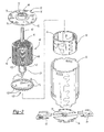
- Figure 2 is an exploded view of the motor of Figure 1.
- Figure 3a is a cross-section view of the end cap of Figure 2 along line 3-3 thereof.
- Figure 3b is a cross-section view of the end cap of Figure 2 prior to deforming of the end cap.
- Figure 4a is an exploded perspective view of the armature assembly of Figure 2.
- Figure 4b is an assembled view of Figure 4a.
- Figure 4c is a cross-section view through lines 4c-4c of Figure 4b.
- Figure 4d is a cross-section view of Figure 4b along line 4d-4d thereof.
- Figure 5 is an enlarged section view of the motor of Figure 1.
- Figure 6a is a perspective view of a fan prior to assembly with the armature assembly.
- Figure 6b is an elevation view partially in section of the armature assembly with the fan attached.
- Figure 7a is an exploded perspective view of the motor can with end caps.
- Figure 7b is a perspective view of one of the end caps on the motor can.
- Figure 7c is an elevation view of the end cap secured to the motor can.
- Figure 8a is a perspective view partially in section of the magnet mechanism for providing an increase resistance to demagnetization.
- Figure 8b is a perspective view partially in section of the magnet mechanism within the motor can.
- Figure 8c is a perspective view partially in section of the motor can being a part of the magnet member.
- Turning to Figure 1, a power tool in accordance with the present invention is illustrated and designated with the
reference numeral 10. Thepower tool 10 is illustrated as a drill; however, any type of power tool such as a screwdriver, sander, rotary tool, clippers, saw or the like which utilize an electric motor may be used with the motor of the present invention. Thepower tool 10 includes ahousing 12 which surrounds amotor 14. Anactivation member 16 is coupled with themotor 14 as well as with apower source 18. Thepower source 18 may be a power cord (AC current) as shown or the power tool may have a battery (DC current). Themotor 14 is coupled with anoutput 20 which may include a transmission 22 and achuck 24 to retain a tool (not shown) with the drill. - The
motor 14 includes amagnetic stator assembly 30 which includes amotor can 32,flux ring 34, andmagnets armature 40 includes ashaft 42, arotor 44 withlaminations 46 andwindings 48, as well as acommutator 50 coupled with theshaft 42. The motor also includes end caps 52 and 54. Theend cap 52 includes abearing 56 which balances one end of theshaft 58 which is coupled with apinion 60.Brushes commutator 50. Abearing 70 is coupled with theend cap 54 to balance rotation of theshaft 42. - Turning to Figures 2 and 3, the
end cap 52 is illustrated. Theend cap 52 has an overall circular configuration with acentral recess 72housing bearing 56. Therecess 72 includes abore 74 which enables passage of theshaft 42. Theend cap 52 also includes a plurality of cut-outs or recesses 76 on the periphery of theend cap 52. Ashoulder 78 is formed by a deformation of a portion of the end capadjacent recess 72. Thedeformation groove 80 may be circular and surround thebearing 56. Alternatively, there may be a number of disjointed groove segments forming a circular pattern. Also, theend cap 52 is generally formed from a metallic material which may be stamped with a desired configuration as well as including the recesses and apertures. - Turning to Figure 3b, the method for forming the end cap will be better explained. Figure 3b illustrates a cross-section of the
end cap 52 prior to thebearing 56 being permanently affixed to theend cap 52. As can be seen, therecess 72 is sized to receive thebearing 56. Thebearing 56 is positioned within therecess 72. Atool 90 having a centeringmember 92 and adeformation member 94 is positioned with respect to the end cap so that the positioningmember 92 fits within the bore of thebearing 56 as well as thebore 74 of theend plate 52. As this occurs, thedeformation member 94 contacts theend cap 52 forming theshoulder 78. Accordingly, thedeformation member 94 may be continuous or discontinuous (as shown in phantom in Figure 3b) to form thegroove 80. - Turning to Figures 4a-4d, parts of the
armature 40 are shown. Here, thelaminations 46,shaft 42 andretainer 96 are shown. Theshaft 42 includes a plurality ofstakes 98 which run longitudinally with respect to the axis of theshaft 42. Thestakes 98, generally four in number, extend a desired distance along the shaft. However, thestakes 98 do not extend to the ends of the shaft. Thus, smooth portions are at each end of theshaft 42. The stakes do have a desired length in order to receive and retain thelaminations 46 as well as theretainer 96. Thelaminations 46, as seen in Figure 4c, have a desired design with a central aperture which is substantially circular. Thelaminations 46 are slid onto the shaft over the smooth ends until they are pressed and retained on thestakes 98. Likewise, theretainer 96 is cylindrical, having a cylindrical bore. Theretainer 96 slides onto the end of the shaft until it contacts thestakes 98. At that time, theretainer 96 is pressed onto the shaft so that the stakes retain theretainer 96 onto theshaft 42. Theretainer 96 is generally metallic or a powder metal part. Accordingly, theretainer 96 can ride directly against the bearing 56 provided that the thrust pressure/velocity limits of the material are not exceeded. This eliminates the need for additional washers between the retainer andsleeve bearing 56. Also, an epoxy coating is on thelaminates 46 andretainer 96 to enhance retention on theshaft 42. - Turning to Figure 5, the
pinion gear 60 is illustrated. Thepinion gear 60 includesteeth 102 as well as acentral bore 104. Also, ashoulder 106 is unitarily formed with thepinion gear 60. Theshoulder 106 has a desired length and extends towards theend cap 52. In themotor 14, it is critical to maintain a clearance 55 between thecommutator 50 andend cap 54. If this clearance is not kept, it is possible that the motor may seize. Theshoulder 106 helps to limit the movement of thearmature shaft 42 andcommutator 50. if thearmature shaft 42 slips in thebearings pinion shoulder 106 eventually contacts thebearing 56 which is fixed to theend cap 52. Accordingly, thearmature shaft 42 may only slip a desired amount so that the commutator clearance is always present to prevent seizing of the motor. - Turning to Figure 6a, the
motor fan 108 is illustrated prior to the attachment with thearmature 40. As can be seen, thefan 108 has an overall disc shape withblades 109 and a plurality of extendingfingers 110. The extendingfingers 110 press intogaps 112 in thelaminations 46. This is illustrated in Figure 6b. Once thefingers 110 are pressed into thegaps 112, thefan 108 is coupled with thearmature 40. After the coupling, an adhesive 114 is placed onto thefingers 110 and laminates 46. At the time the adhesive 114 is applied, it is wet and the adhesive is a first color, preferably a bright yellow. After the adhesive 114 cures, thefan 108 is permanently secured to the armature. After the curing of the adhesive 114, the adhesive changes color to a second color. Preferably, the cured color is brown. Thus, a person assembling the motor may visually determine whether or not the fan has been permanently secured to the laminates. The color brown indicating that the adhesive is cured and, in turn, the fan affixed to thelaminates 46. Alternatively, if the fan has just been adhered to thelaminates 46, the bright yellow color is present. Thus, the assembler can easily visually detect whether or not the armature, which includes thefan 108, is ready for additional assembly. - Turning to Figure 7a, the motor can 32 is shown. The motor can 32 includes a plurality of extending
fingers 116. Thefingers 116 mesh with therecesses 76 in theend cap 52. Also,end cap 54 includesrecesses 118 which mesh with the extendingfingers 116 on the other end of the motor can 32. As seen in Figure 7b, theend plate 52 has been coupled with the motor can 32 so that thefingers 116 and recesses 76 are in a meshing condition. After the positioning, thefingers 116 are cold worked to deform thefingers 116 so that the end caps are permanently secured to the motor can 32 as illustrated in Figure 7c. As can be seen in Figure 2, thefingers 116 are deformed, having a trapezoidal shape, so that the fingers secure theend cap 52 to themotor housing 32. This cold working is also utilized to retainend cap 54 to the motor can 32. - Turning to Figure 8a, the
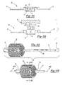
demagnetization stator member 30 is shown. Thedemagnetization member 30 includes aring 120 as well asmagnets ring 120 includes at least oneaperture 122 strategically positioned to receive magnetic material as themagnets ring 120. Also, the ring includes anchors 124 like those described in pendingU.S. Patent Application Serial No. 09/764,004 filed January 17, 2001 apertures 122 may be strategically positioned around thering 120. Themagnets - Turning to Figure 8b, a motor can 32' is illustrated with
apertures 126. Here, thering 120 would be secured to the motor can prior to the injection molding of themagnets apertures 122 would be aligned withapertures 126. Accordingly, when the magnetic material is injection into thering 120, the magnet material would pass through theaperture 122 intoaperture 126 of the can 32'. This, in turn, increases the thickness of the magnet at the desired position. This thickness, in turn, increases resistance to demagnetization. - Turning to Figure 8c, an additional motor can 32" is shown. Here, the
magnets apertures 126, as well as the anchors 124, provide their desired features as mentioned above. - The
ring 120 includes analignment notch 140. Thealignment notch 140, during the injection molding of themagnets ring 120 in the tooling which, in turn, enables proper positioning of themagnets ring 120 so that the magnets are molded onto the anchors. Also, thenotch 140 is used to align theflux ring 120 with respect to the motor can during assembly. Again, thenotch 140 is placed over an aligning pin as the ring is positioned into the motor can. - While the above detailed description describes the preferred embodiment of the present invention, the invention is susceptible to modification, variation and alteration without deviating from the scope and fair meaning of the subjoined claims.
Claims (28)
- An armature shaft assembly for a motor, comprising:a shaft, said shaft including a plurality of stakes in its outer peripheral surface;said stakes extending a desired length along a longitudinal axis of the shaft;a plurality of laminates on said shaft, said plurality of laminates have an aperture which slips onto said shaft and is pressed on and retained by said plurality of stakes on said shaft;a retaining member having a bore, said bore enabling said retainer to slip on said shaft, said retainer pressed onto said plurality of stakes to maintain position of said retainer on said shaft.
- The armature shaft assembly according to Claim 1, wherein said retainer is a metal part.
- The armature shaft assembly according to Claim 1 or 2, wherein a coating is placed on said laminates and retainer to provide additional resistance against movement with respect to said shaft.
- A motor assembly, comprising:a motor can having two ends, an end cap at each end of said motor can;an armature mechanism in said motor can, said armature mechanism including a shaft, a portion of said shaft extending from one of said end caps to receive a pinion gear;a stator assembly including a pair of magnets;a pinion gear positioned on said shaft, said pinion gear including a shoulder extending toward said end cap, said shoulder adapted to limit movement of said armature mechanism in said motor can.
- The motor assembly according to Claim 4, wherein said shoulder having a desired length to enable a clearance between a commutator and the other end cap in the event of movement of the armature mechanism.
- A method for securing a fan to a motor armature, comprising:providing a motor armature assembly;coupling a fan with said motor armature assembly;placing an adhesive on said fan to secure said fan to said armature assembly, said adhesive being a first color when said adhesive is wet;enabling said adhesive to cure, permanently fixing said fan to said armature assembly wherein upon curing said adhesive changes from said first color to a second color.
- The method according to Claim 6, wherein said first color being yellow.
- The method according to Claim 6 or 7, wherein said second color being brown.
- A method of securing an end cap with a motor can, comprising:providing a motor can including a plurality of extending fingers;providing an end cap including a plurality of recesses corresponding in number to said plurality of extending fingers;positioning said end cap on said motor can such that said plurality of fingers mesh with said plurality of recesses;cold working said extending fingers;deforming said plurality extending finger by said cold working; andsecuring said end cap with said motor can by said plurality of deformed extending fingers.
- The method according to Claim 9, further comprising centering said end cap on said motor can.
- A motor having an increased resistance to demagnetization, comprising:a motor can having two ends with end caps coupled with said two ends of said motor can;an armature assembly rotatably positioned in said motor can;magnetic mechanism positioned in said motor can, said magnetic mechanism including a housing with at least one magnet secured to said housing, said housing including at least one aperture, said at least one magnet including material filling said at least one aperture, wherein a magnet localization occurs at said at least one aperture reducing susceptibility to demagnetization.
- The motor according to Claim 11, wherein said housing being a ring member positioned in said motor can.
- The motor can according to Claim 12, wherein said motor can includes at least one aperture aligned with said housing at least one aperture and said motor can aperture receiving magnet material.
- The motor can according to any one of claims 11 to 13, wherein said motor can being said housing and including said at least one aperture.
- A motor assembly, comprising:a motor can having two ends, an end cap at each end of said motor can;an armature assembly in said motor can, said armature assembly including a shaft, said shaft including a plurality of stakes in its outer peripheral surface;said stakes extending a desired length along a longitudinal axis of the shaft;a plurality of laminates on said shaft, said plurality of laminates have an aperture which slips onto said shaft and is pressed on and retained by said plurality of stakes on said shaft;a retaining member having a bore, said bore enabling said retainer to slip on said shaft, said retainer pressed onto said plurality of stakes to maintain position of said retainer on said shaft received in said end caps; anda stator assembly including a pair of magnets surrounding said armature assembly, said stator assembly positioned in said motor can.
- The armature shaft assembly according to Claim 15, wherein said retainer is a metal part.
- The armature shaft assembly according to Claim 15 or 16, wherein a coating is placed on said laminates and retainer to provide additional resistance against movement with respect to said shaft.
- A power tool, comprising:a housing;a motor positioned in said housing, said motor comprising:a motor can having two ends, an end cap at each end of said motor can;an armature assembly in said motor can, said armature assembly including a shaft, said shaft including a plurality of stakes in its outer peripheral surface;said stakes extending a desired length along a longitudinal axis of the shaft;a plurality of laminates on said shaft, said plurality of laminates have an aperture which slips onto said shaft and is pressed on and retained by said plurality of stakes on said shaft;a retaining member having a bore, said bore enabling said retainer to slip on said shaft, said retainer pressed onto said plurality of stakes to maintain position of said retainer on said shaft received in said end caps; anda stator assembly including a pair of magnets surrounding said armature assembly, said stator assembly positioned in said motor can;an output coupled with said motor;an activation member coupled with said motor for energizing said motor; anda power source coupled with said motor and activation member for providing power to said tool.
- The armature shaft assembly according to Claim 18, wherein said retainer is a metal part.
- The armature shaft assembly according to Claim 18 or 19, wherein a coating is placed on said laminates and retainer to provide additional resistance against movement with respect to said shaft.
- A power tool, comprising:a housing;a motor positioned in said housing, said motor comprising:a motor can having two ends, an end cap at each end of said motor can;an armature mechanism in said motor can, said armature mechanism including a shaft, a portion of said shaft extending from one of said end caps to receive a pinion gear;a stator assembly including a pair of magnets;a pinion gear positioned on said shaft, said pinion gear including a shoulder extending toward said end cap, said shoulder adapted to limit movement of said armature mechanism in said motor can;an output coupled with said motor;an activation member coupled with said motor for energizing said motor; anda power source coupled with said motor and activation member for providing power to said tool.
- The motor assembly according to Claim 21, wherein said shoulder having a desired length to enable a clearance between a commutator and the other end cap in the event of movement of the armature mechanism.
- A power tool, comprising:a housing;a motor positioned in said housing, said motor comprising:a motor can having two ends with end caps coupled with said two ends of said motor can;an armature assembly rotatably positioned in said motor can;magnetic mechanism positioned in said motor can, said magnetic mechanism including a housing with at least one magnet secured to said housing, said housing including at least one aperture, said at least one magnet including material filling said at least one aperture, wherein a magnet localization occurs at said at least one aperture reducing susceptibility to demagnetization;an output coupled with said motor;an activation member coupled with said motor for energizing said motor; anda power source coupled with said motor and activation member for providing power to said tool.
- The motor according to Claim 23, wherein said housing being a ring member positioned in said motor can.
- The motor can according to Claim 24, wherein said motor can includes at least one aperture aligned with said housing at least one aperture and said motor can aperture receiving magnet material.
- The motor can according to any one of claims 23 to 25, wherein said motor can being said housing and including said at least one aperture.
- A flux ring for a motor comprising:an annular member;a member for securing at least one magnet on said annular member; andan alignment member, said alignment member associated with said annular member for aligning said annular member with the magnets and with a motor can.
- The flux ring according to Claim 27 wherein said alignment member being a notch in said annular member.
Priority Applications (1)
| Application Number | Priority Date | Filing Date | Title |
|---|---|---|---|
| EP08100467A EP1912315A3 (en) | 2001-06-14 | 2002-06-13 | Motor for a power tool |
Applications Claiming Priority (3)
| Application Number | Priority Date | Filing Date | Title |
|---|---|---|---|
| US29826101P | 2001-06-14 | 2001-06-14 | |
| US10/170,996 US6781267B2 (en) | 2001-06-14 | 2002-06-12 | Motor for a power tool |
| EP02734797A EP1406740A4 (en) | 2001-06-14 | 2002-06-13 | Motor for a power tool |
Related Parent Applications (1)
| Application Number | Title | Priority Date | Filing Date |
|---|---|---|---|
| EP02734797A Division EP1406740A4 (en) | 2001-06-14 | 2002-06-13 | Motor for a power tool |
Related Child Applications (1)
| Application Number | Title | Priority Date | Filing Date |
|---|---|---|---|
| EP08100467A Division EP1912315A3 (en) | 2001-06-14 | 2002-06-13 | Motor for a power tool |
Publications (3)
| Publication Number | Publication Date |
|---|---|
| EP1705782A2 true EP1705782A2 (en) | 2006-09-27 |
| EP1705782A3 EP1705782A3 (en) | 2007-07-11 |
| EP1705782B1 EP1705782B1 (en) | 2009-04-15 |
Family
ID=36847839
Family Applications (1)
| Application Number | Title | Priority Date | Filing Date |
|---|---|---|---|
| EP06114179A Expired - Lifetime EP1705782B1 (en) | 2001-06-14 | 2002-06-13 | Motor for a power tool |
Country Status (1)
| Country | Link |
|---|---|
| EP (1) | EP1705782B1 (en) |
Citations (5)
| Publication number | Priority date | Publication date | Assignee | Title |
|---|---|---|---|---|
| FR709084A (en) | 1931-01-09 | 1931-08-03 | Method for fixing the brush pack of the rotors of electric machines | |
| GB2003674A (en) | 1977-09-05 | 1979-03-14 | Matsushita Electric Ind Co Ltd | Armature of double insulation construction and method of making the same |
| US4377762A (en) | 1980-01-07 | 1983-03-22 | Hitachi, Ltd. | Rotary electric machine rotor and a method of manufacturing the same |
| US4793054A (en) | 1985-11-12 | 1988-12-27 | Black & Decker Inc. | Alignment system for permanent magnet motors |
| US5907208A (en) | 1997-01-27 | 1999-05-25 | Hilti Aktiengesellschaft | Rotor for an electric motor |
-
2002
- 2002-06-13 EP EP06114179A patent/EP1705782B1/en not_active Expired - Lifetime
Patent Citations (5)
| Publication number | Priority date | Publication date | Assignee | Title |
|---|---|---|---|---|
| FR709084A (en) | 1931-01-09 | 1931-08-03 | Method for fixing the brush pack of the rotors of electric machines | |
| GB2003674A (en) | 1977-09-05 | 1979-03-14 | Matsushita Electric Ind Co Ltd | Armature of double insulation construction and method of making the same |
| US4377762A (en) | 1980-01-07 | 1983-03-22 | Hitachi, Ltd. | Rotary electric machine rotor and a method of manufacturing the same |
| US4793054A (en) | 1985-11-12 | 1988-12-27 | Black & Decker Inc. | Alignment system for permanent magnet motors |
| US5907208A (en) | 1997-01-27 | 1999-05-25 | Hilti Aktiengesellschaft | Rotor for an electric motor |
Also Published As
| Publication number | Publication date |
|---|---|
| EP1705782B1 (en) | 2009-04-15 |
| EP1705782A3 (en) | 2007-07-11 |
Similar Documents
| Publication | Publication Date | Title |
|---|---|---|
| US7372181B2 (en) | Rotor for brushless motor and brushless motor | |
| EP2076954B1 (en) | Motor with permanent magnets and method of manufacturing; power tool with same | |
| EP1002357B1 (en) | Rotor for an electrical machine | |
| US7728464B2 (en) | Pneumatic tool with integrated electricity generator | |
| US6548935B1 (en) | Clan pole generator | |
| US5907208A (en) | Rotor for an electric motor | |
| US6522042B1 (en) | Anchoring system for injection molded magnets on a flux ring or motor housing | |
| US6781267B2 (en) | Motor for a power tool | |
| CA2181161A1 (en) | Motor including embedded permanent magnet-rotor | |
| US20060197404A1 (en) | Internal cooling fan with a non-repeating blade configuration | |
| CN109155556B (en) | Rotor and method for producing a rotor | |
| US20200403469A1 (en) | Electric motor | |
| WO1989003604A1 (en) | Lamination to rotor shaft retention method utilizing spring pins | |
| JP2008160973A (en) | Rotor and rotary electric machine | |
| JP6997037B2 (en) | Brushless motor and its manufacturing method | |
| US20120126639A1 (en) | Stator housing assembly having overmolded magnets | |
| EP1912315A2 (en) | Motor for a power tool | |
| JP5036833B2 (en) | Rotating electric machine | |
| US20040174089A1 (en) | Rotor of dynamo-electric machine | |
| EP0908798A3 (en) | Electronic watch | |
| EP1705782A2 (en) | Motor for a power tool | |
| US7274121B2 (en) | Systems and methods for fastening internal cooling fans to claw-pole electro-mechanical machines | |
| JP7034778B2 (en) | Brushless motor and its manufacturing method | |
| JP6668443B1 (en) | 2-phase hollow stepping motor | |
| US6707198B1 (en) | Armature shaft retainer |
Legal Events
| Date | Code | Title | Description |
|---|---|---|---|
| PUAI | Public reference made under article 153(3) epc to a published international application that has entered the european phase |
Free format text: ORIGINAL CODE: 0009012 |
|
| 17P | Request for examination filed |
Effective date: 20060518 |
|
| AC | Divisional application: reference to earlier application |
Ref document number: 1406740 Country of ref document: EP Kind code of ref document: P |
|
| AK | Designated contracting states |
Kind code of ref document: A2 Designated state(s): AT BE CH CY DE DK ES FI FR GB GR IE IT LI LU MC NL PT SE TR |
|
| AX | Request for extension of the european patent |
Extension state: AL BA HR MK YU |
|
| RIC1 | Information provided on ipc code assigned before grant |
Ipc: H02K 1/17 20060101ALI20070220BHEP Ipc: H02K 15/12 20060101ALI20070220BHEP Ipc: H02K 15/14 20060101AFI20060817BHEP Ipc: H02K 9/06 20060101ALI20070220BHEP Ipc: H02K 5/15 20060101ALI20070220BHEP Ipc: H02K 15/02 20060101ALI20070220BHEP Ipc: H02K 5/173 20060101ALI20070220BHEP |
|
| PUAL | Search report despatched |
Free format text: ORIGINAL CODE: 0009013 |
|
| AK | Designated contracting states |
Kind code of ref document: A3 Designated state(s): AT BE CH CY DE DK ES FI FR GB GR IE IT LI LU MC NL PT SE TR |
|
| AX | Request for extension of the european patent |
Extension state: AL BA HR MK YU |
|
| 17Q | First examination report despatched |
Effective date: 20070830 |
|
| AKX | Designation fees paid |
Designated state(s): AT BE CH CY DE DK ES FI FR GB GR IE IT LI LU MC NL PT SE TR |
|
| GRAP | Despatch of communication of intention to grant a patent |
Free format text: ORIGINAL CODE: EPIDOSNIGR1 |
|
| GRAS | Grant fee paid |
Free format text: ORIGINAL CODE: EPIDOSNIGR3 |
|
| GRAA | (expected) grant |
Free format text: ORIGINAL CODE: 0009210 |
|
| AC | Divisional application: reference to earlier application |
Ref document number: 1406740 Country of ref document: EP Kind code of ref document: P |
|
| AK | Designated contracting states |
Kind code of ref document: B1 Designated state(s): AT BE CH CY DE DK ES FI FR GB GR IE IT LI LU MC NL PT SE TR |
|
| REG | Reference to a national code |
Ref country code: CH Ref legal event code: EP Ref country code: GB Ref legal event code: FG4D |
|
| REG | Reference to a national code |
Ref country code: IE Ref legal event code: FG4D |
|
| REF | Corresponds to: |
Ref document number: 60232032 Country of ref document: DE Date of ref document: 20090528 Kind code of ref document: P |
|
| REG | Reference to a national code |
Ref country code: SE Ref legal event code: TRGR |
|
| NLV1 | Nl: lapsed or annulled due to failure to fulfill the requirements of art. 29p and 29m of the patents act | ||
| PG25 | Lapsed in a contracting state [announced via postgrant information from national office to epo] |
Ref country code: AT Free format text: LAPSE BECAUSE OF FAILURE TO SUBMIT A TRANSLATION OF THE DESCRIPTION OR TO PAY THE FEE WITHIN THE PRESCRIBED TIME-LIMIT Effective date: 20090415 Ref country code: ES Free format text: LAPSE BECAUSE OF FAILURE TO SUBMIT A TRANSLATION OF THE DESCRIPTION OR TO PAY THE FEE WITHIN THE PRESCRIBED TIME-LIMIT Effective date: 20090726 Ref country code: PT Free format text: LAPSE BECAUSE OF FAILURE TO SUBMIT A TRANSLATION OF THE DESCRIPTION OR TO PAY THE FEE WITHIN THE PRESCRIBED TIME-LIMIT Effective date: 20090915 |
|
| PG25 | Lapsed in a contracting state [announced via postgrant information from national office to epo] |
Ref country code: NL Free format text: LAPSE BECAUSE OF FAILURE TO SUBMIT A TRANSLATION OF THE DESCRIPTION OR TO PAY THE FEE WITHIN THE PRESCRIBED TIME-LIMIT Effective date: 20090415 |
|
| PG25 | Lapsed in a contracting state [announced via postgrant information from national office to epo] |
Ref country code: DK Free format text: LAPSE BECAUSE OF FAILURE TO SUBMIT A TRANSLATION OF THE DESCRIPTION OR TO PAY THE FEE WITHIN THE PRESCRIBED TIME-LIMIT Effective date: 20090415 Ref country code: MC Free format text: LAPSE BECAUSE OF NON-PAYMENT OF DUE FEES Effective date: 20090630 |
|
| REG | Reference to a national code |
Ref country code: CH Ref legal event code: PL |
|
| PLBE | No opposition filed within time limit |
Free format text: ORIGINAL CODE: 0009261 |
|
| STAA | Information on the status of an ep patent application or granted ep patent |
Free format text: STATUS: NO OPPOSITION FILED WITHIN TIME LIMIT |
|
| PG25 | Lapsed in a contracting state [announced via postgrant information from national office to epo] |
Ref country code: BE Free format text: LAPSE BECAUSE OF FAILURE TO SUBMIT A TRANSLATION OF THE DESCRIPTION OR TO PAY THE FEE WITHIN THE PRESCRIBED TIME-LIMIT Effective date: 20090415 |
|
| 26N | No opposition filed |
Effective date: 20100118 |
|
| REG | Reference to a national code |
Ref country code: FR Ref legal event code: ST Effective date: 20100226 |
|
| REG | Reference to a national code |
Ref country code: IE Ref legal event code: MM4A |
|
| PG25 | Lapsed in a contracting state [announced via postgrant information from national office to epo] |
Ref country code: CH Free format text: LAPSE BECAUSE OF NON-PAYMENT OF DUE FEES Effective date: 20090630 Ref country code: IE Free format text: LAPSE BECAUSE OF NON-PAYMENT OF DUE FEES Effective date: 20090613 Ref country code: LI Free format text: LAPSE BECAUSE OF NON-PAYMENT OF DUE FEES Effective date: 20090630 Ref country code: FR Free format text: LAPSE BECAUSE OF NON-PAYMENT OF DUE FEES Effective date: 20090630 |
|
| PG25 | Lapsed in a contracting state [announced via postgrant information from national office to epo] |
Ref country code: GR Free format text: LAPSE BECAUSE OF FAILURE TO SUBMIT A TRANSLATION OF THE DESCRIPTION OR TO PAY THE FEE WITHIN THE PRESCRIBED TIME-LIMIT Effective date: 20090716 |
|
| PGFP | Annual fee paid to national office [announced via postgrant information from national office to epo] |
Ref country code: SE Payment date: 20100629 Year of fee payment: 9 |
|
| PG25 | Lapsed in a contracting state [announced via postgrant information from national office to epo] |
Ref country code: FI Free format text: LAPSE BECAUSE OF FAILURE TO SUBMIT A TRANSLATION OF THE DESCRIPTION OR TO PAY THE FEE WITHIN THE PRESCRIBED TIME-LIMIT Effective date: 20090415 |
|
| PG25 | Lapsed in a contracting state [announced via postgrant information from national office to epo] |
Ref country code: LU Free format text: LAPSE BECAUSE OF NON-PAYMENT OF DUE FEES Effective date: 20090613 |
|
| PG25 | Lapsed in a contracting state [announced via postgrant information from national office to epo] |
Ref country code: TR Free format text: LAPSE BECAUSE OF FAILURE TO SUBMIT A TRANSLATION OF THE DESCRIPTION OR TO PAY THE FEE WITHIN THE PRESCRIBED TIME-LIMIT Effective date: 20090415 |
|
| PG25 | Lapsed in a contracting state [announced via postgrant information from national office to epo] |
Ref country code: CY Free format text: LAPSE BECAUSE OF FAILURE TO SUBMIT A TRANSLATION OF THE DESCRIPTION OR TO PAY THE FEE WITHIN THE PRESCRIBED TIME-LIMIT Effective date: 20090415 |
|
| REG | Reference to a national code |
Ref country code: SE Ref legal event code: EUG |
|
| PG25 | Lapsed in a contracting state [announced via postgrant information from national office to epo] |
Ref country code: SE Free format text: LAPSE BECAUSE OF NON-PAYMENT OF DUE FEES Effective date: 20110614 |
|
| PGFP | Annual fee paid to national office [announced via postgrant information from national office to epo] |
Ref country code: DE Payment date: 20150629 Year of fee payment: 14 Ref country code: GB Payment date: 20150629 Year of fee payment: 14 |
|
| PGFP | Annual fee paid to national office [announced via postgrant information from national office to epo] |
Ref country code: IT Payment date: 20150625 Year of fee payment: 14 |
|
| REG | Reference to a national code |
Ref country code: DE Ref legal event code: R119 Ref document number: 60232032 Country of ref document: DE |
|
| GBPC | Gb: european patent ceased through non-payment of renewal fee |
Effective date: 20160613 |
|
| PG25 | Lapsed in a contracting state [announced via postgrant information from national office to epo] |
Ref country code: DE Free format text: LAPSE BECAUSE OF NON-PAYMENT OF DUE FEES Effective date: 20170103 |
|
| PG25 | Lapsed in a contracting state [announced via postgrant information from national office to epo] |
Ref country code: GB Free format text: LAPSE BECAUSE OF NON-PAYMENT OF DUE FEES Effective date: 20160613 |
|
| PG25 | Lapsed in a contracting state [announced via postgrant information from national office to epo] |
Ref country code: IT Free format text: LAPSE BECAUSE OF NON-PAYMENT OF DUE FEES Effective date: 20160613 |