EP1705367A1 - Internal combustion engine with at least two cylinder rows - Google Patents
Internal combustion engine with at least two cylinder rows Download PDFInfo
- Publication number
- EP1705367A1 EP1705367A1 EP05027770A EP05027770A EP1705367A1 EP 1705367 A1 EP1705367 A1 EP 1705367A1 EP 05027770 A EP05027770 A EP 05027770A EP 05027770 A EP05027770 A EP 05027770A EP 1705367 A1 EP1705367 A1 EP 1705367A1
- Authority
- EP
- European Patent Office
- Prior art keywords
- air intake
- internal combustion
- combustion engine
- fuel
- intake system
- Prior art date
- Legal status (The legal status is an assumption and is not a legal conclusion. Google has not performed a legal analysis and makes no representation as to the accuracy of the status listed.)
- Granted
Links
- 238000002485 combustion reaction Methods 0.000 title claims abstract description 18
- 239000000446 fuel Substances 0.000 claims abstract description 25
- 230000001419 dependent effect Effects 0.000 description 1
- 238000002347 injection Methods 0.000 description 1
- 239000007924 injection Substances 0.000 description 1
Images


Classifications
-
- F—MECHANICAL ENGINEERING; LIGHTING; HEATING; WEAPONS; BLASTING
- F02—COMBUSTION ENGINES; HOT-GAS OR COMBUSTION-PRODUCT ENGINE PLANTS
- F02M—SUPPLYING COMBUSTION ENGINES IN GENERAL WITH COMBUSTIBLE MIXTURES OR CONSTITUENTS THEREOF
- F02M35/00—Combustion-air cleaners, air intakes, intake silencers, or induction systems specially adapted for, or arranged on, internal-combustion engines
- F02M35/10—Air intakes; Induction systems
- F02M35/10006—Air intakes; Induction systems characterised by the position of elements of the air intake system in direction of the air intake flow, i.e. between ambient air inlet and supply to the combustion chamber
- F02M35/10026—Plenum chambers
- F02M35/10039—Intake ducts situated partly within or on the plenum chamber housing
-
- F—MECHANICAL ENGINEERING; LIGHTING; HEATING; WEAPONS; BLASTING
- F02—COMBUSTION ENGINES; HOT-GAS OR COMBUSTION-PRODUCT ENGINE PLANTS
- F02B—INTERNAL-COMBUSTION PISTON ENGINES; COMBUSTION ENGINES IN GENERAL
- F02B27/00—Use of kinetic or wave energy of charge in induction systems, or of combustion residues in exhaust systems, for improving quantity of charge or for increasing removal of combustion residues
- F02B27/02—Use of kinetic or wave energy of charge in induction systems, or of combustion residues in exhaust systems, for improving quantity of charge or for increasing removal of combustion residues the systems having variable, i.e. adjustable, cross-sectional areas, chambers of variable volume, or like variable means
- F02B27/0226—Use of kinetic or wave energy of charge in induction systems, or of combustion residues in exhaust systems, for improving quantity of charge or for increasing removal of combustion residues the systems having variable, i.e. adjustable, cross-sectional areas, chambers of variable volume, or like variable means characterised by the means generating the charging effect
- F02B27/0247—Plenum chambers; Resonance chambers or resonance pipes
- F02B27/0263—Plenum chambers; Resonance chambers or resonance pipes the plenum chamber and at least one of the intake ducts having a common wall, and the intake ducts wrap partially around the plenum chamber, i.e. snail-type
-
- F—MECHANICAL ENGINEERING; LIGHTING; HEATING; WEAPONS; BLASTING
- F02—COMBUSTION ENGINES; HOT-GAS OR COMBUSTION-PRODUCT ENGINE PLANTS
- F02B—INTERNAL-COMBUSTION PISTON ENGINES; COMBUSTION ENGINES IN GENERAL
- F02B27/00—Use of kinetic or wave energy of charge in induction systems, or of combustion residues in exhaust systems, for improving quantity of charge or for increasing removal of combustion residues
- F02B27/02—Use of kinetic or wave energy of charge in induction systems, or of combustion residues in exhaust systems, for improving quantity of charge or for increasing removal of combustion residues the systems having variable, i.e. adjustable, cross-sectional areas, chambers of variable volume, or like variable means
- F02B27/0226—Use of kinetic or wave energy of charge in induction systems, or of combustion residues in exhaust systems, for improving quantity of charge or for increasing removal of combustion residues the systems having variable, i.e. adjustable, cross-sectional areas, chambers of variable volume, or like variable means characterised by the means generating the charging effect
- F02B27/0268—Valves
- F02B27/0273—Flap valves
-
- F—MECHANICAL ENGINEERING; LIGHTING; HEATING; WEAPONS; BLASTING
- F02—COMBUSTION ENGINES; HOT-GAS OR COMBUSTION-PRODUCT ENGINE PLANTS
- F02M—SUPPLYING COMBUSTION ENGINES IN GENERAL WITH COMBUSTIBLE MIXTURES OR CONSTITUENTS THEREOF
- F02M35/00—Combustion-air cleaners, air intakes, intake silencers, or induction systems specially adapted for, or arranged on, internal-combustion engines
- F02M35/10—Air intakes; Induction systems
- F02M35/10006—Air intakes; Induction systems characterised by the position of elements of the air intake system in direction of the air intake flow, i.e. between ambient air inlet and supply to the combustion chamber
- F02M35/10026—Plenum chambers
- F02M35/10065—Valves arranged in the plenum chamber
-
- F—MECHANICAL ENGINEERING; LIGHTING; HEATING; WEAPONS; BLASTING
- F02—COMBUSTION ENGINES; HOT-GAS OR COMBUSTION-PRODUCT ENGINE PLANTS
- F02M—SUPPLYING COMBUSTION ENGINES IN GENERAL WITH COMBUSTIBLE MIXTURES OR CONSTITUENTS THEREOF
- F02M35/00—Combustion-air cleaners, air intakes, intake silencers, or induction systems specially adapted for, or arranged on, internal-combustion engines
- F02M35/10—Air intakes; Induction systems
- F02M35/10209—Fluid connections to the air intake system; their arrangement of pipes, valves or the like
- F02M35/10216—Fuel injectors; Fuel pipes or rails; Fuel pumps or pressure regulators
-
- F—MECHANICAL ENGINEERING; LIGHTING; HEATING; WEAPONS; BLASTING
- F02—COMBUSTION ENGINES; HOT-GAS OR COMBUSTION-PRODUCT ENGINE PLANTS
- F02M—SUPPLYING COMBUSTION ENGINES IN GENERAL WITH COMBUSTIBLE MIXTURES OR CONSTITUENTS THEREOF
- F02M35/00—Combustion-air cleaners, air intakes, intake silencers, or induction systems specially adapted for, or arranged on, internal-combustion engines
- F02M35/10—Air intakes; Induction systems
- F02M35/104—Intake manifolds
- F02M35/116—Intake manifolds for engines with cylinders in V-arrangement or arranged oppositely relative to the main shaft
-
- F—MECHANICAL ENGINEERING; LIGHTING; HEATING; WEAPONS; BLASTING
- F02—COMBUSTION ENGINES; HOT-GAS OR COMBUSTION-PRODUCT ENGINE PLANTS
- F02M—SUPPLYING COMBUSTION ENGINES IN GENERAL WITH COMBUSTIBLE MIXTURES OR CONSTITUENTS THEREOF
- F02M55/00—Fuel-injection apparatus characterised by their fuel conduits or their venting means; Arrangements of conduits between fuel tank and pump F02M37/00
- F02M55/02—Conduits between injection pumps and injectors, e.g. conduits between pump and common-rail or conduits between common-rail and injectors
- F02M55/025—Common rails
-
- F—MECHANICAL ENGINEERING; LIGHTING; HEATING; WEAPONS; BLASTING
- F02—COMBUSTION ENGINES; HOT-GAS OR COMBUSTION-PRODUCT ENGINE PLANTS
- F02B—INTERNAL-COMBUSTION PISTON ENGINES; COMBUSTION ENGINES IN GENERAL
- F02B27/00—Use of kinetic or wave energy of charge in induction systems, or of combustion residues in exhaust systems, for improving quantity of charge or for increasing removal of combustion residues
- F02B27/02—Use of kinetic or wave energy of charge in induction systems, or of combustion residues in exhaust systems, for improving quantity of charge or for increasing removal of combustion residues the systems having variable, i.e. adjustable, cross-sectional areas, chambers of variable volume, or like variable means
- F02B27/0205—Use of kinetic or wave energy of charge in induction systems, or of combustion residues in exhaust systems, for improving quantity of charge or for increasing removal of combustion residues the systems having variable, i.e. adjustable, cross-sectional areas, chambers of variable volume, or like variable means characterised by the charging effect
- F02B27/0215—Oscillating pipe charging, i.e. variable intake pipe length charging
-
- Y—GENERAL TAGGING OF NEW TECHNOLOGICAL DEVELOPMENTS; GENERAL TAGGING OF CROSS-SECTIONAL TECHNOLOGIES SPANNING OVER SEVERAL SECTIONS OF THE IPC; TECHNICAL SUBJECTS COVERED BY FORMER USPC CROSS-REFERENCE ART COLLECTIONS [XRACs] AND DIGESTS
- Y02—TECHNOLOGIES OR APPLICATIONS FOR MITIGATION OR ADAPTATION AGAINST CLIMATE CHANGE
- Y02T—CLIMATE CHANGE MITIGATION TECHNOLOGIES RELATED TO TRANSPORTATION
- Y02T10/00—Road transport of goods or passengers
- Y02T10/10—Internal combustion engine [ICE] based vehicles
- Y02T10/12—Improving ICE efficiencies
Definitions
- the invention relates to an internal combustion engine having at least two rows of cylinder banks according to the features of the preamble of patent claim 1.
- EP 0 405 612 B1 discloses an internal combustion engine with cylinders arranged in a V-shape relative to each other, in which corresponding fuel injectors are fastened to the cylinder heads in the inside V.
- a centrally arranged air intake module extends.
- the object of the invention is, in an internal combustion engine with a common rail injection, to integrate the fuel supply device as a whole in a space-saving manner or in the internal combustion engine.
- the central fuel supply line (common rail) is arranged centrally below the air intake system of the internal combustion engine, being branched off from the two longitudinal sides of the common rail individual lines which are connected to injectors fixed in the cylinder head ,
- the high-pressure fuel supply unit is - except for the high-pressure pump - completely arranged in the inner-V and protected from external damage.
- the generally audible injectors can be shielded by the air intake system.
- the modular air intake system has on its underside recesses in which the fuel individual lines are added to save space.
- the air intake system is designed shell-shaped, wherein the recesses for the individual fuel lines are formed in a lower shell of the air intake system.
- the air intake system has an upper and lower shell and a middle part arranged therebetween, in which air intake ducts for the individual cylinders are formed in the assembled state.
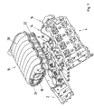
- Fig. 1 the parts of an internal combustion engine are shown, which are required to explain the claimed subject matter.
- the internal combustion engine is, for example, designed as a V8 engine and accordingly has two cylinder heads 2 and 4. Between the two cylinder heads 2 and 4, a central fuel supply line 6, hereinafter referred to as a common rail, is arranged in the inside V of the engine. From the two longitudinal sides of the common rail 6 branch off fuel individual lines 8a to 8h, each leading to a fixed in the cylinder heads 2, 4 fuel injector 10a to 10h. The fuel injectors 10a to 10h are each secured in pairs in the cylinder head by means of a hold-down 12a to 12d. On the common rail 6, a fuel supply line 14 is attached, which is connected to a high-pressure fuel pump 16. The high pressure pump 16 is attached to the front side of the cylinder head 4 and is driven by a camshaft, not shown.
- an air intake system - hereinafter referred to as air intake module 18 - is arranged between the two cylinder banks. Via a central opening 20 to which a throttle body, not shown, is attached, combustion air is sucked in a known manner and supplied to the individual cylinders via air intake ducts 18 formed in the air intake module.
- the air intake module 18 is formed in three parts and has an upper and lower shell 20 and 22, between which a central part 24 is arranged. In the assembled state, corresponding air intake passages 26a to 26h are formed by the three parts 20, 22 and 24. Between the air intake ducts 26a to 26h, recesses 28a to 28h in which the individual fuel lines 8a to 8h run or are received are formed in the lower shell 22.
- the air intake passages 26a to 26h extend helically and have corresponding switching flaps 30, via which two different intake pipe lengths can be represented as a function of the engine speed.
- the long suction tube is switched, while with the switching flap 30 open, the combustion air passes via the released opening to the individual cylinders.
- the air intake passages 26a to 26h can be represented with maximum radii and minimal flow losses they pass by the side of the injectors 10a to 10h.
Landscapes
- Engineering & Computer Science (AREA)
- Chemical & Material Sciences (AREA)
- Combustion & Propulsion (AREA)
- Mechanical Engineering (AREA)
- General Engineering & Computer Science (AREA)
- Fuel-Injection Apparatus (AREA)
- Cylinder Crankcases Of Internal Combustion Engines (AREA)
Abstract
Description
Die Erfindung betrifft eine Brennkraftmaschine mit mindestens zwei Zylinderbankreihen gemäß den Merkmalen des Oberbegriffs des Patentanspruchs 1.The invention relates to an internal combustion engine having at least two rows of cylinder banks according to the features of the preamble of patent claim 1.
Aus der EP 0 405 612 B1 ist eine Brennkraftmaschine mit V-förmig zueinander angeordneten Zylindern bekannt, bei der im Innen-V an den Zylinderköpfen entsprechende Kraftstoffinjektoren befestigt sind. Darüber erstreckt sich ein zentral angeordnetes Luftansaugmodul.
Aufgabe der Erfindung ist es, bei einer Brennkraftmaschine mit einer Common-Rail-Einspritzung die Kraftstoffversorgungseinrichtung insgesamt platzsparend an bzw. in der Brennkraftmaschine zu integrieren.The object of the invention is, in an internal combustion engine with a common rail injection, to integrate the fuel supply device as a whole in a space-saving manner or in the internal combustion engine.
Die Aufgabe wird durch die im Patentanspruch 1 angegebenen Merkmale gelöst.The object is solved by the features specified in claim 1.
Es wird auf vorteilhafte Art und Weise vorgeschlagen, dass die zentrale Kraftstoff-Versorgungsleitung (Common-Rail) zentral unterhalb der Luftansauganlage der Brennkraftmaschine angeordnet ist, wobei von den beiden Längsseiten des Common-Rails Einzelleitungen abgezweigt sind, die an im Zylinderkopf befestigte Injektoren angeschlossen sind. Damit ist die Kraftstoff-Hochdruckversorgungseinheit - bis auf die Hochdruckpumpe - komplett im Innen-V angeordnet und vor äußeren Beschädigungen geschützt. Die akustisch allgemein auffälligen Einspritzventile können durch die Luftansauganlage abgeschirmt werden.It is proposed in an advantageous manner that the central fuel supply line (common rail) is arranged centrally below the air intake system of the internal combustion engine, being branched off from the two longitudinal sides of the common rail individual lines which are connected to injectors fixed in the cylinder head , Thus, the high-pressure fuel supply unit is - except for the high-pressure pump - completely arranged in the inner-V and protected from external damage. The generally audible injectors can be shielded by the air intake system.
Durch die in den Unteransprüchen angegebenen Merkmale sind weitere vorteilhafte Ausgestaltungen und Weiterbildungen der Brennkraftmaschine möglich.The features specified in the dependent claims further advantageous embodiments and refinements of the internal combustion engine are possible.
Die modulartig aufgebaute Luftansauganlage weist auf ihrer Unterseite Ausnehmungen auf, in denen die Kraftstoff-Einzelleitungen platzsparend aufgenommen sind.The modular air intake system has on its underside recesses in which the fuel individual lines are added to save space.
Die Luftansauganlage ist schalenförmig ausgebildet, wobei die Ausnehmungen für die Kraftstoff-Einzelleitungen in einer Unterschale der Luftansauganlage ausgebildet sind.The air intake system is designed shell-shaped, wherein the recesses for the individual fuel lines are formed in a lower shell of the air intake system.
Die Luftansauganlage weist eine Ober- und Unterschale sowie ein dazwischen angeordnetes Mittelteil auf, in denen im zusammengesetzten Zustand Luftansaugkanäle für die einzelnen Zylinder ausgebildet sind.The air intake system has an upper and lower shell and a middle part arranged therebetween, in which air intake ducts for the individual cylinders are formed in the assembled state.
Ein Ausführungsbeispiel der Erfindung ist in der Zeichnung dargestellt und wird im nachfolgenden näher beschrieben.An embodiment of the invention is illustrated in the drawing and will be described in more detail below.
- Fig. 1Fig. 1
- eine Perspektivansicht auf einen Teil einer Brennkraftmaschine unda perspective view of a part of an internal combustion engine and
- Fig. 2Fig. 2
- eine Ansicht auf eine Kraftstoff-Versorgungseinrichtung der Brennkraftmaschine von unten gesehen unda view of a fuel supply device of the internal combustion engine seen from below and
- Fig. 3Fig. 3
- einen Querschnitt durch eine Luftansauganlage.a cross section through an air intake system.
In Fig. 1 sind die Teile einer Brennkraftmaschine dargestellt, die zur Erläuterung des beanspruchten Gegenstandes erforderlich sind. Die Brennkraftmaschine ist bspw. als V8-Motor ausgebildet und weist dementsprechend zwei Zylinderköpfe 2 und 4 auf. Zwischen den beiden Zylinderköpfen 2 und 4 ist im Innen-V des Motors eine zentrale Kraftstoff-Versorgungsleitung 6, im Folgenden als Common-Rail bezeichnet, angeordnet. Von den beiden Längsseiten des Common-Rails 6 zweigen Kraftstoff-Einzelleitungen 8a bis 8h ab, die jeweils zu einem in den Zylinderköpfen 2, 4 befestigten Kraftstoff-Injektor 10a bis 10h führen. Die Kraftstoff-Injektoren 10a bis 10h sind dabei jeweils paarweise mittels eines Niederhalters 12a bis 12d im Zylinderkopf befestigt. Am Common-Rail 6 ist eine Kraftstoff-Versorgungsleitung 14 befestigt, die an eine Kraftstoff-Hochdruckpumpe 16 angeschlossen ist. Die Hochdruckpumpe 16 ist stirnseitig am Zylinderkopf 4 befestigt und wird über eine nicht dargestellte Nockenwelle angetrieben.In Fig. 1, the parts of an internal combustion engine are shown, which are required to explain the claimed subject matter. The internal combustion engine is, for example, designed as a V8 engine and accordingly has two
Oberhalb der aus dem Common-Rail 6 und den Kraftstoff-Injektoren 10a bis 10h bestehenden Kraftstoff-Versorgungseinrichtung ist zwischen den beiden Zylinderbänken eine Luftansauganlage - im Folgenden als Luftansaugmodul 18 bezeichnet - angeordnet. Über eine zentrale Öffnung 20, an der ein nicht dargestelltes Drosselklappengehäuse befestigt ist, wird auf bekannte Art und Weise Verbrennungsluft angesaugt und über im Luftansaugmodul 18 ausgebildete Luftansaugkanäle den einzelnen Zylindern zugeführt. Das Luftansaugmodul 18 ist dreiteilig ausgebildet und weist eine Ober- und Unterschale 20 und 22 auf, zwischen denen ein Mittelteil 24 angeordnet ist. Im zusammengebauten Zustand werden durch die drei Teile 20, 22 und 24 entsprechende Luftansaugkanäle 26a bis 26h ausgebildet. Zwischen den Luftansaugkanälen 26a bis 26h sind in der Unterschale 22 Ausnehmungen 28a bis 28h ausgebildet, in denen die Kraftstoff-Einzelleitungen 8a bis 8h verlaufen bzw. aufgenommen sind.Above the fuel supply device consisting of the
Wie ein Querschnitt durch das Luftansaugmodul 18 zeigt (siehe Figur 3), verlaufen die Luftansaugkanäle 26a bis 26h spiralförmig und weisen entsprechende Schaltklappen 30 auf, über die in Abhängigkeit von der Motordrehzahl zwei unterschiedliche Saugrohrlängen darstellbar sind. In der geschlossenen Stellung (siehe Figur 3) ist dabei das lange Saugrohr geschaltet, während bei geöffneter Schaltklappe 30 die Verbrennungsluft über die freigegebene Öffnung zu den einzelnen Zylindern gelangt.As shown by a cross section through the air intake module 18 (see FIG. 3), the
Dadurch, dass in der Unterschale 22 entsprechende Freiräume bzw. Ausnehmungen 28a bis 28h für die Aufnahme der Injektoren 10a bis 10h und der Kraftstoff- Einzelleitungen 8a bis 8h ausgebildet sind, können die Luftansaugkanäle 26a bis 26h mit maximalen Radien und minimalen Strömungsverlusten dargestellt werden, da sie seitlich an den Injektoren 10a bis 10h vorbeilaufen.Because corresponding clearances or
Claims (4)
Applications Claiming Priority (1)
| Application Number | Priority Date | Filing Date | Title |
|---|---|---|---|
| DE102005009117A DE102005009117A1 (en) | 2005-03-01 | 2005-03-01 | Internal combustion engine with at least two rows of cylinder banks |
Publications (2)
| Publication Number | Publication Date |
|---|---|
| EP1705367A1 true EP1705367A1 (en) | 2006-09-27 |
| EP1705367B1 EP1705367B1 (en) | 2008-09-03 |
Family
ID=35501202
Family Applications (1)
| Application Number | Title | Priority Date | Filing Date |
|---|---|---|---|
| EP05027770A Active EP1705367B1 (en) | 2005-03-01 | 2005-12-19 | Internal combustion engine with at least two cylinder rows |
Country Status (5)
| Country | Link |
|---|---|
| US (1) | US7278403B2 (en) |
| EP (1) | EP1705367B1 (en) |
| JP (1) | JP2006242181A (en) |
| AT (1) | ATE407289T1 (en) |
| DE (2) | DE102005009117A1 (en) |
Cited By (1)
| Publication number | Priority date | Publication date | Assignee | Title |
|---|---|---|---|---|
| EP2402589A3 (en) * | 2010-06-29 | 2012-01-18 | Suzuki Motor Corporation | Fuel feed system for V-type engine |
Families Citing this family (2)
| Publication number | Priority date | Publication date | Assignee | Title |
|---|---|---|---|---|
| JP2010196678A (en) * | 2009-02-27 | 2010-09-09 | Nissan Motor Co Ltd | Collector tank structure |
| JP5160492B2 (en) * | 2009-03-27 | 2013-03-13 | 本田技研工業株式会社 | V-type engine fuel supply system |
Citations (5)
| Publication number | Priority date | Publication date | Assignee | Title |
|---|---|---|---|---|
| EP0352820A2 (en) * | 1988-07-29 | 1990-01-31 | Mazda Motor Corporation | Intake system for V-type engine |
| EP0405612A1 (en) * | 1989-06-30 | 1991-01-02 | Mazda Motor Corporation | Intake system for internal combustion engine |
| EP0892170A1 (en) * | 1997-01-16 | 1999-01-20 | Isuzu Motors Limited | Fuel injection device for diesel engines |
| US20020083924A1 (en) * | 2001-01-04 | 2002-07-04 | Siemens Automotive Inc. | Monocoque manifold assembly |
| US20020179025A1 (en) * | 2000-07-27 | 2002-12-05 | Glovatsky Andrew Z | Integrated powertrain control system for large engines |
Family Cites Families (5)
| Publication number | Priority date | Publication date | Assignee | Title |
|---|---|---|---|---|
| US4570602A (en) * | 1982-08-23 | 1986-02-18 | General Motors Corporation | Fuel rail |
| JPH0868340A (en) * | 1994-05-19 | 1996-03-12 | Yamaha Motor Co Ltd | V-type engine having cam shaft driving device |
| US6367451B2 (en) * | 1998-10-05 | 2002-04-09 | Sanshin Kogyo Kabushiki Kaisha | Fuel supply system for a direct injected outboard engine |
| JP2001159381A (en) * | 1999-12-03 | 2001-06-12 | Isuzu Motors Ltd | Common rail type v-type diesel engine |
| US6691661B2 (en) * | 2002-01-31 | 2004-02-17 | S & S Cycle, Inc. | Tuned induction system for a motorcycle |
-
2005
- 2005-03-01 DE DE102005009117A patent/DE102005009117A1/en not_active Withdrawn
- 2005-12-19 DE DE502005005255T patent/DE502005005255D1/en active Active
- 2005-12-19 AT AT05027770T patent/ATE407289T1/en not_active IP Right Cessation
- 2005-12-19 EP EP05027770A patent/EP1705367B1/en active Active
-
2006
- 2006-02-21 JP JP2006043431A patent/JP2006242181A/en not_active Withdrawn
- 2006-02-28 US US11/363,322 patent/US7278403B2/en active Active
Patent Citations (5)
| Publication number | Priority date | Publication date | Assignee | Title |
|---|---|---|---|---|
| EP0352820A2 (en) * | 1988-07-29 | 1990-01-31 | Mazda Motor Corporation | Intake system for V-type engine |
| EP0405612A1 (en) * | 1989-06-30 | 1991-01-02 | Mazda Motor Corporation | Intake system for internal combustion engine |
| EP0892170A1 (en) * | 1997-01-16 | 1999-01-20 | Isuzu Motors Limited | Fuel injection device for diesel engines |
| US20020179025A1 (en) * | 2000-07-27 | 2002-12-05 | Glovatsky Andrew Z | Integrated powertrain control system for large engines |
| US20020083924A1 (en) * | 2001-01-04 | 2002-07-04 | Siemens Automotive Inc. | Monocoque manifold assembly |
Cited By (2)
| Publication number | Priority date | Publication date | Assignee | Title |
|---|---|---|---|---|
| EP2402589A3 (en) * | 2010-06-29 | 2012-01-18 | Suzuki Motor Corporation | Fuel feed system for V-type engine |
| US9062645B2 (en) | 2010-06-29 | 2015-06-23 | Suzuki Motor Corporation | Fuel feed system for V-type engine |
Also Published As
| Publication number | Publication date |
|---|---|
| DE102005009117A1 (en) | 2006-09-07 |
| EP1705367B1 (en) | 2008-09-03 |
| JP2006242181A (en) | 2006-09-14 |
| US20060201457A1 (en) | 2006-09-14 |
| US7278403B2 (en) | 2007-10-09 |
| ATE407289T1 (en) | 2008-09-15 |
| DE502005005255D1 (en) | 2008-10-16 |
Similar Documents
| Publication | Publication Date | Title |
|---|---|---|
| DE69708598T2 (en) | FUEL INJECTION VALVE MOUNTING FOR SHAPED INLET MANIFOLD WITH INTEGRATED FUEL PIPE | |
| DE102012207617B4 (en) | Turbo-charged combustion engine with dedicated exhaust gas recirculation | |
| EP1030050B2 (en) | Exhaust gas recirculation system | |
| EP0489238B2 (en) | Inlet collector | |
| DE102004047943B4 (en) | Multi-cylinder internal combustion engine | |
| EP0975869B1 (en) | Fuel injection system for an internal combustion engine with a common rail | |
| DE102014100739B4 (en) | PARTLY INTEGRATED EXHAUST GASKET | |
| DE102007057310A1 (en) | Internal combustion engine, has exhaust manifolds supplying exhaust gas into turbocharger that is connectable to engine and integral with respective assigned cylinder heads of cylinders | |
| DE112006000567T5 (en) | Charged internal combustion engine with EGR device | |
| EP2256314A1 (en) | Combustion engine | |
| DE102004060003A1 (en) | Common rail fuel supply for multicylinder engine has at least two high-pressure pumps connected via separate pump line to one of supply lines | |
| DE102016010267B4 (en) | Exhaust device for an engine | |
| EP1705367B1 (en) | Internal combustion engine with at least two cylinder rows | |
| DE102009053986A1 (en) | Flange device and Saugnalage | |
| DE102012203701B4 (en) | Exhaust turbocharger module and internal combustion engine equipped with it | |
| DE4110597C2 (en) | Intake air intake system for a multi-cylinder internal combustion engine | |
| EP0628707A1 (en) | System for the air supply of an internal combustion engine | |
| DE2331755C3 (en) | Intake manifold on reciprocating internal combustion engines | |
| DE3833846A1 (en) | Intake arrangement for an internal combustion engine with a flap generating a swirl and/or turbulence | |
| DE102009008011A1 (en) | internal combustion engine | |
| DE102009036443A1 (en) | Internal combustion engine for passenger car, has ventilation system that is fluidically connected with crank case by two plug devices that are plugged into respective plug receptacles | |
| DE19509002C2 (en) | Thermostat mounting structure | |
| DE112020000271T5 (en) | FUEL DISTRIBUTOR | |
| EP3268598A1 (en) | Internal combustion engine comprising attachment part | |
| DE102004008255B4 (en) | Device for changing the charge movement of the intake air in internal combustion engines |
Legal Events
| Date | Code | Title | Description |
|---|---|---|---|
| PUAI | Public reference made under article 153(3) epc to a published international application that has entered the european phase |
Free format text: ORIGINAL CODE: 0009012 |
|
| AK | Designated contracting states |
Kind code of ref document: A1 Designated state(s): AT BE BG CH CY CZ DE DK EE ES FI FR GB GR HU IE IS IT LI LT LU LV MC NL PL PT RO SE SI SK TR |
|
| AX | Request for extension of the european patent |
Extension state: AL BA HR MK YU |
|
| 17P | Request for examination filed |
Effective date: 20070327 |
|
| 17Q | First examination report despatched |
Effective date: 20070425 |
|
| AKX | Designation fees paid |
Designated state(s): AT DE FR GB IT SE |
|
| GRAP | Despatch of communication of intention to grant a patent |
Free format text: ORIGINAL CODE: EPIDOSNIGR1 |
|
| RAP1 | Party data changed (applicant data changed or rights of an application transferred) |
Owner name: DR. ING. H.C. F. PORSCHE AKTIENGESELLSCHAFT |
|
| RAP1 | Party data changed (applicant data changed or rights of an application transferred) |
Owner name: DR. ING. H.C. F. PORSCHE AKTIENGESELLSCHAFT |
|
| GRAS | Grant fee paid |
Free format text: ORIGINAL CODE: EPIDOSNIGR3 |
|
| GRAA | (expected) grant |
Free format text: ORIGINAL CODE: 0009210 |
|
| AK | Designated contracting states |
Kind code of ref document: B1 Designated state(s): AT DE FR GB IT SE |
|
| REG | Reference to a national code |
Ref country code: GB Ref legal event code: FG4D Free format text: NOT ENGLISH |
|
| REF | Corresponds to: |
Ref document number: 502005005255 Country of ref document: DE Date of ref document: 20081016 Kind code of ref document: P |
|
| PLBE | No opposition filed within time limit |
Free format text: ORIGINAL CODE: 0009261 |
|
| STAA | Information on the status of an ep patent application or granted ep patent |
Free format text: STATUS: NO OPPOSITION FILED WITHIN TIME LIMIT |
|
| 26N | No opposition filed |
Effective date: 20090604 |
|
| PG25 | Lapsed in a contracting state [announced via postgrant information from national office to epo] |
Ref country code: IT Free format text: LAPSE BECAUSE OF FAILURE TO SUBMIT A TRANSLATION OF THE DESCRIPTION OR TO PAY THE FEE WITHIN THE PRESCRIBED TIME-LIMIT Effective date: 20080903 |
|
| PG25 | Lapsed in a contracting state [announced via postgrant information from national office to epo] |
Ref country code: SE Free format text: LAPSE BECAUSE OF FAILURE TO SUBMIT A TRANSLATION OF THE DESCRIPTION OR TO PAY THE FEE WITHIN THE PRESCRIBED TIME-LIMIT Effective date: 20081203 |
|
| PG25 | Lapsed in a contracting state [announced via postgrant information from national office to epo] |
Ref country code: AT Free format text: LAPSE BECAUSE OF NON-PAYMENT OF DUE FEES Effective date: 20081219 |
|
| REG | Reference to a national code |
Ref country code: FR Ref legal event code: TP |
|
| REG | Reference to a national code |
Ref country code: GB Ref legal event code: 732E Free format text: REGISTERED BETWEEN 20110310 AND 20110316 |
|
| REG | Reference to a national code |
Ref country code: GB Ref legal event code: 732E Free format text: REGISTERED BETWEEN 20110331 AND 20110406 |
|
| REG | Reference to a national code |
Ref country code: FR Ref legal event code: PLFP Year of fee payment: 11 |
|
| REG | Reference to a national code |
Ref country code: FR Ref legal event code: PLFP Year of fee payment: 12 |
|
| REG | Reference to a national code |
Ref country code: FR Ref legal event code: PLFP Year of fee payment: 13 |
|
| PGFP | Annual fee paid to national office [announced via postgrant information from national office to epo] |
Ref country code: GB Payment date: 20181218 Year of fee payment: 14 Ref country code: FR Payment date: 20181220 Year of fee payment: 14 |
|
| GBPC | Gb: european patent ceased through non-payment of renewal fee |
Effective date: 20191219 |
|
| PG25 | Lapsed in a contracting state [announced via postgrant information from national office to epo] |
Ref country code: GB Free format text: LAPSE BECAUSE OF NON-PAYMENT OF DUE FEES Effective date: 20191219 Ref country code: FR Free format text: LAPSE BECAUSE OF NON-PAYMENT OF DUE FEES Effective date: 20191231 |
|
| P01 | Opt-out of the competence of the unified patent court (upc) registered |
Effective date: 20230526 |
|
| PGFP | Annual fee paid to national office [announced via postgrant information from national office to epo] |
Ref country code: DE Payment date: 20231206 Year of fee payment: 19 |