EP1705279A2 - Needle plate - Google Patents
Needle plate Download PDFInfo
- Publication number
- EP1705279A2 EP1705279A2 EP06005737A EP06005737A EP1705279A2 EP 1705279 A2 EP1705279 A2 EP 1705279A2 EP 06005737 A EP06005737 A EP 06005737A EP 06005737 A EP06005737 A EP 06005737A EP 1705279 A2 EP1705279 A2 EP 1705279A2
- Authority
- EP
- European Patent Office
- Prior art keywords
- needle plate
- engagement
- needle
- plate
- sewing machine
- Prior art date
- Legal status (The legal status is an assumption and is not a legal conclusion. Google has not performed a legal analysis and makes no representation as to the accuracy of the status listed.)
- Withdrawn
Links
- 230000007246 mechanism Effects 0.000 claims abstract description 57
- 238000009958 sewing Methods 0.000 claims abstract description 48
- 239000004744 fabric Substances 0.000 claims abstract description 7
- 230000001105 regulatory effect Effects 0.000 claims description 12
- 238000003825 pressing Methods 0.000 claims description 4
- 239000002184 metal Substances 0.000 description 10
- 230000009466 transformation Effects 0.000 description 6
- 238000010276 construction Methods 0.000 description 5
- 229920003002 synthetic resin Polymers 0.000 description 5
- 239000000057 synthetic resin Substances 0.000 description 5
- 238000005520 cutting process Methods 0.000 description 4
- 230000013011 mating Effects 0.000 description 4
- 229910000831 Steel Inorganic materials 0.000 description 3
- 230000000149 penetrating effect Effects 0.000 description 3
- 239000010959 steel Substances 0.000 description 3
- 238000005452 bending Methods 0.000 description 2
- 239000000428 dust Substances 0.000 description 2
- 238000013024 troubleshooting Methods 0.000 description 2
- 238000004140 cleaning Methods 0.000 description 1
- 238000006073 displacement reaction Methods 0.000 description 1
- 230000000694 effects Effects 0.000 description 1
- 230000002452 interceptive effect Effects 0.000 description 1
- 239000004973 liquid crystal related substance Substances 0.000 description 1
- 238000004519 manufacturing process Methods 0.000 description 1
- 239000007769 metal material Substances 0.000 description 1
- 238000000034 method Methods 0.000 description 1
- 230000004048 modification Effects 0.000 description 1
- 238000012986 modification Methods 0.000 description 1
- 230000035515 penetration Effects 0.000 description 1
- 230000008569 process Effects 0.000 description 1
- 230000009467 reduction Effects 0.000 description 1
- 238000009877 rendering Methods 0.000 description 1
Images



Classifications
-
- D—TEXTILES; PAPER
- D05—SEWING; EMBROIDERING; TUFTING
- D05B—SEWING
- D05B73/00—Casings
- D05B73/04—Lower casings
- D05B73/12—Slides; Needle plates
Definitions
- the present disclosure relates to a needle plate for a sewing machine placed on the upper surface of a sewing machine bed having a horizontal hook mechanism therein.
- a needle plate is constructed by a first needle plate fixed to a sewing machine bed and a second needle plate (referred to as a first lid in the above disclosure) detachably attached to the sewing machine bed.
- the first needle plate is formed in an oblong shape and is made of a metal plate (steel plate) having a needle hole for penetration of sewing needle therethrough and a square hole for projecting and retracting a feed dog for feeding a workpiece cloth.
- the second needle plate is formed in an L-shape and is located along the left and front side of the first needle plate.
- the first needle plate is made of metal so as to tolerate the striking of the sewing needle thereon.
- the second needle plate on the other hand, merely supports a cloth on the upper surface thereof and is not struck by the sewing needle.
- the second needle plate is made of synthetic resin for cost reduction.
- the following construction is adopted to render the detachable attachment of the second needle plate.
- Four pieces of L-shaped (in side view) hooks are integrally provided on the underside of the second needle plate; more specifically, on the left and right portions respectively of the longitudinal ends of the underside.
- four recesses are provided for accommodating the aforementioned hooks; three on the sewing machine bed and one on the underside of the first needle plate.
- a positioning notch for lateral positioning is formed on the right rear-end portion of the second needle plate, and a protrusion for engagement with the notch is provided on the right front-end portion of the first needle plate.
- a small (few mm) space is defined between the front end of the second needle plate and an opening of the sewing machine bed.
- the second needle plate upon attachment of the second needle plate, the second needle plate is fitted from above to an opening portion defined on the sewing machine bed 1 and slightly (few mm) pushed toward the rear.
- the elasticity of the four hooks engages themselves with each recess.
- the second needle plate upon removing the second needle plate, the second needle plate is slightly (few mm) pulled toward the front so as to be disengaged, and thereafter lifted upward.
- the second needle plate made of synthetic resin since the second needle plate made of synthetic resin is engaged with the needle plate and the sewing machine bed by the elasticity of the second needle plate itself, the operational burden incurred by the second needle plate upon attachment/detachment thereof causes the transformation of the hooks. Also, the location of the second needle plate attached to the sewing machine bed with respect to the location of the first needle plate fixed to the sewing machine frame is prone to vary, therefore causing some degree of rattle in the mating surfaces of the first and the second needle plates.
- the second needle plate also from metal and detachably attaching the second needle plate to the first needle plate with a fastening screw.
- this requires tightening and loosening of the screw upon attachment/detachment of the second needle plate, consequently requiring tools therefor, and complicating the attachment/detachment work.
- an object of the present disclosure is to provide a needle plate including a first needle plate fixed to a sewing machine bed and a second needle plate detachably attached to the first needle plate, wherein the attachment/detachment of the second needle plate can be easily carried out while preventing the transformation thereof caused by the operational burden of the attachment/detachment operation and further reducing the rattle at the mating surfaces of the first and the second needle plates.
- the needle plate of the present disclosure includes a first needle plate provided on a sewing machine bed and having a needle hole through which a sewing needle can be penetrated and a square hole through which a feed dog for feeding a process cloth is projected and retracted.
- the needle plate also includes a second needle plate arranged in front of the first needle plate and above a horizontal hook mechanism and which is attached detachably to the first needle plate.
- the needle plate is further provided with an engagement mechanism in which the second needle plate is slid into engagement with the first needle plate and a disengagement mechanism for disengagement of the engagement mechanism.
- the second needle plate By sliding the second needle plate to the first needle plate, the second needle plate becomes engaged with the first needle plate, consequently rendering the attachment of the second needle plate.
- the second needle plate can be removed from the first needle plate by disengagement of the engagement mechanism by the disengagement mechanism and sliding the second needle plate in a direction opposing the above direction. At this point, the detachment/attachment of the second needle plate from the first needle plate can be easily carried out by sliding the second needle plate.
- the first needle plate prefferably be made of metal to tolerate the striking of the sewing needle thereto.
- the second needle plate may, but not limited to, be made of synthetic resin or metal. It is preferable for the second needle plate to be made of metal to secure strength.
- various sliding directions such as lateral or longitudinal directions can be adopted for the sliding of the second needle plate.
- the engagement mechanism is constituted by an engaged portion provided on the first needle plate and an a thin-plate elastic member having a base end thereof fixed to the second needle plate and a free end thereof provided with an engagement portion engagable with the engaged portion.
- Such engagement mechanism allows a construction in which the engagement portion is engaged with the engaged portion by the elasticity of the thin-plate elastic member.
- the engagement mechanism can be realized with a simple construction in addition to reducing the height of the engagement mechanism. Such construction prevents the engagement mechanism from interfering with the parts for the horizontal hook mechanism or the like residing below the needle plate.
- the disengagement mechanism by providing the disengagement mechanism with an operation member capable of pressing the elastic member in a direction resisting the elasticity thereof; the engagement between the engaged portion and the engagement portion can be disengaged. Also, the engagement mechanism can be simplified.
- the second needle plate By providing the disengagement mechanism to the second needle plate, the second needle plate can be slid while carrying out the disengagement operation, thereby simplifying the removal of the second needle plate.
- the engagement mechanism may be provided in a location corresponding to the lateral ends of the first needle plate, thus reducing the rattle of the first and the second needle plates upon attachment of the second needle plate.
- the engagement of the engaged portion and the engagement portion may be rendered by mutually engaging a recess or an aperture or a protrusion provided on the engaged portion and the engagement portion. Thus, reliable engagement is attained.
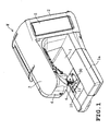
- FIG. 1 shows an external appearance of a household sewing machine M according the present embodiment.
- the sewing machine M has a laterally elongated sewing machine bed 1, a pillar 2 extending upright from the right side of the sewing machine bed 1, and an arm 3 extending leftward from the upper portion of the pillar 2.
- a head 4 is provided on the left end of the arm 3.
- a vertically oriented liquid crystal display 5 is provided on the front surface of the pillar 2.
- a needle bar (not shown) to which a sewing needle 6 is attached is provided in the underside of the head 4.
- a needle bar vertically moving mechanism (not shown) vertically moving the needle bar, a thread take-up drive mechanism (not shown) driving the thread take-up in synchronization with the vertical movement of the needle bar, and the like are provided inside the arm 3.
- the sewing machine bed 1 has a removable auxiliary table 1a in the left front portion thereof.
- a needle plate 10 according to the present embodiment is provided on the upper surface of the sewing machine bed 1. The details of the needle plate 10 will be described later.
- a horizontal hook mechanism known in the art is located below the needle plate 10 inside the sewing machine bed 1.
- the horizontal hook mechanism includes an outer hook having a tip, a non-rotatable inner hook provided inside the outer hook and a drive mechanism, or the like, rotating the outer hook in synchronization with the vertical movement of the needle bar.
- a bobbin is detachably set to the inner hook.
- a cloth feed mechanism including a feed dog for feeding a cloth and a feed dog drive mechanism longitudinally and vertically driving the feed dog in synchronization with the vertical movement of the needle bar is provided inside the sewing machine bed 1.
- FIG. 2 is a plan view of the needle plate 10.
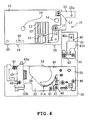
- FIGS. 3 and 4 illustrate the underside of the needle plate 10 which is the reverse side of FIG. 2, in which the left and right are the opposite of FIG. 2.
- the needle plate 10 includes a first needle plate 11 fixed to the sewing machine bed 1 and a second needle plate 30 detachably attached to the first needle plate 11.
- the needle plate 10 is constructed by mating the first and the second needle plates 11 and 30.
- the second needle plate 30 is engaged (attached) with the first needle plate 11 by sliding the second needle plate 30 from front (the lower side in FIG. 2) to rear (the upper side in FIG. 2) with respect to the first needle plate 10.
- the first needle plate 11 is made of a metal material (for example a steel plate) formed in a laterally elongated oblong plate-form.
- a needle hole 12 in a substantially oval form elongated in the lateral direction and through which a sewing needle 6 can be penetrated is formed on the first needle plate 11 and below the sewing needle 6.
- a plurality of (seven) square holes 13 in a linear form elongated in the longitudinal direction are provided in the front and rear and to the left and right of the needle hole 12.
- the feed dog moves in the front and rear direction while projecting and retracting from the square holes 13.
- penetrating holes 14 are defined in two locations; the central-right portion and the rear-left end portion of the needle hole 12.
- the first needle plate 11 is fixed to the frame of the sewing machine bed 1 by inserting screws (not shown) respectively to the penetrating holes 14.
- an engagement receiving member 15 made of metal plate is provided on the underside of the first needle plate 11, more specifically, on the rear portion of the left edge (the right side in FIGS. 3 and 4).
- the engagement receiving member 15 is made of metal plate in a reversed L-shape, and fixed to the first needle plate 11 by a screw 17 so as to protrude to the left from the left edge of the first needle plate 11.
- a protrusion 15a is provided on the left end underside of the engagement receiving member 15.
- a laterally elongated recess 16 is formed in the right front end portion (left side in FIGS. 2 and 3) .
- the protrusion 15a and the recess 16 function as engaged portions.
- three engagement protrusions 18, 19 and 20 are provided in a forwardly protruding manner.
- the second needle plate 30 is made of a metal plate (for example, a steel plate) formed in a substantially L-shape in entirety and located along the left and the front edge of the first needle plate 11.
- a metal plate for example, a steel plate
- an opening 30a for bobbin replacement is formed in the front (above the inner hook of the horizontal hook mechanism) of the needle hole 12 and the square hole 13 of the second needle plate 30.
- a transparent needle plate lid 34 made of synthetic resin open/closeably covering the opening 30a is provided on the second needle plate 30. The needle plate lid 34 is coplanar with the second needle plate 30.
- a covering lid 36 is provided on the upper surface of the second needle plate 30 and in the left side of the needle plate lid 34.
- the cover lid 36 is coplanar with the second needle plate 30.
- a vertically penetrating second guide groove 39 is formed between the second needle plate 30 and the curved left edge of the cover lid 36.
- a cutting blade for cutting the bobbin thread is mounted on the underside of the cover lid 36, more specifically, on the terminating end (front end) of the second guide groove 39.
- an oblong opening 30b is formed on the right side of opening 30a of the second needle plate 30.
- a lock member 35 is provided on the underside of the second needle plate 30, and an operation tab therefor is arranged slidably in the lateral direction inside the oblong opening 30b.
- the needle plate lid 34 is locked in a closed state when the lock member 35 is positioned in the left inside the oblong aperture 30b as shown in FIG. 2.
- the needle plate lid 34 can be released (removed) by rightwardly sliding the lock member 35 inside the oblong aperture 30b.
- An oblong opening 30c is formed on the rear end portion of the left edge of the second needle plate 30.
- a disengagement button 33 serving as an operation member is pressably arranged in the oblong opening 30c from the underside.
- the disengagement button 33 is a component of a later described disengagement mechanism.
- the operation tab of the lock member 35 and the upper surface of the disengagement button 33 are positioned substantially in the same height as the upper surface of the second needle plate 30.
- an engagement recess 52, engagement recess (not shown) and engagement recess 45 (refer to FIG. 3 and 4) engaging with engagement protrusions 20, 19 and 18 respectively are integrally provided in the rear edge of the second needle plate 30, that is, the portion that is mated with the front edge of the first needle plate 11.
- a first bobbin thread guide plate 31 is fixed on the left (right side in the figures) front side of the underside of the second needle plate 30 by two screws 46.
- a second bobbin thread guide plate 32 is fixed by two screws 47 in the right side (left side in the figures) .
- a bobbin passage 38 continuing to the opening 30a is defined between the first bobbin thread guide plate 31 and the second bobbin thread guide plate 32. The bobbin can be attached/detached through the bobbin passage 38.
- a thread guide portion 31a in a substantially cresent form for leftwardly guiding the bobbin thread drawn from the bobbin is integrally provided on the right end of the first bobbin thread guide plate 31.
- the thread guide portion 31a is positioned in a location lowered from the upper surface of the second needle plate 30 by the amount of vertical thickness of the needle plate lid 34 and a first guide groove 37 in a circumferential shape is formed between the thread guide portion 31a and the second bobbin thread guide plate 32 in front of the thread guide portion 31a.
- the terminating end (rear end) of the first guide groove 37 is continued to the starting end (rear end) of a second guide groove 39.
- attachment/detachment (replacement) of the bobbin to/from the horizontal hook mechanism can be carried out through the bobbin passage 38 with the needle plate lid 34 removed from the second needle plate 30.
- the bobbin thread is properly set and appropriate length of thread can be drawn from the bobbin.
- an engagement member 40 serving as the elastic member composed of a plate spring formed in a thin plate and a regulating member 41 functioning as an anti-bend stopper are provided on the underside of the second needle plate 30, more specifically, on the rear left-end portion thereof.
- the front ends of the engagement member 40 and the regulating member 41 are placed atop one another and fixed to the second needle plate 30 by two screws 42.
- the engagement member 40 is formed in a substantially L-shape when viewed from above.
- the free end of the rear end portion of the engagement member 40 is bent in the lower oblique direction.
- An aperture 40a serving as an engagement portion is formed in a location which is slightly in front of the bent portion of the engagement member 40 and corresponding to the protrusion 15a of the engagement receiving member 15.
- the aperture 40a engages with the protrusion 15a by the elasticity of the engagement member 40 upon attaching the second needle plate 30 to the first needle plate 11.
- the protrusion 15a of the engagement receiving member 15 and the aperture 40a of the engagement member 40 constitute the first engagement mechanism 49 (refer to FIGS. 3 and 5).
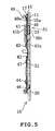
- the underside of the disengagement button 33 contacts the upper surface of the engagement member 40, in a portion slightly in front of the aperture 40a.
- the engagement portion 40 is bent downward consequently disengaging the aperture 40a and the protrusion 15a.
- the regulating member 41 has a mounting portion 41a (refer to FIG. 5) on the front end thereof.
- the rear end of the mounting portion 41a is formed in a lowered step defining a regulating portion 41b serving as an anti-bend stopper.
- the mounting portion 41a being placed between the engagement member 40 and the underside of the second needle plate 30 is attached with a screw 42.
- the regulating portion 41b is arranged on the underside of the engagement member 40, in a portion corresponding to the disengagement button 33, slightly spaced apart from the engagement member 40.
- the disengagement button 33, engagement member 40 and the regulating member 41 constitute the disengagement mechanism 51.
- an engagement member 43 serving as an elastic member made of plate spring is provided near the right end of the second bobbin thread guide plate 43.
- the engagement member 43 is formed in a thin plate elongated in the longitudinal direction, the front end thereof having a longer lateral length than the plate spring mounting portion 32b.
- the lateral ends of the engagement member 43 are bent in the upward direction so as to hold the plate spring mounting portion 32b from the left and right side.
- the base end (front end) of the engagement member 43 is mounted on the plate spring mounting member 32b of the second bobbin thread guide plate 32 by a screw 44.
- an aperture through which the screw 44 of the engagement member 43 is passed is formed in a longitudinally elongate hole and the mounting position of the engagement member 43 is longitudinally adjustable.
- a protrusion 43a serving as an engagement portion bent in a substantially V-shape in side view is provided on the free end of the rear end portion of the engagement member 43.
- the protrusion 43a is engaged with a recess 16 of the first needle plate 11 by the elasticity of the engagement member 43 upon attaching the second needle plate 30 to the first needle plate 11.
- the protrusion 43a of the engagement member 43 and the recess 16 of the first needle plate 11 constitute the second engagement mechanism 50 (refer to FIGS. 3 and 6) .
- the protrusion 43a and the recess 16 are disengaged.
- the needle plate 10 includes a first needle plate 11 fixed to the sewing machine bed 1 and a second needle plate 30 detachably attached to the first needle plate 11.
- the second needle plate 30 When the second needle plate 30 is detached, the upper surface (front and the left side portion) of the sewing machine bed 1 reveals an L-shaped opening so as to expose the horizontal hook mechanism.
- the user is able to easily clean the horizontal hook and carry out trouble shooting work such as removal of the bobbin thread tangled to the horizontal hook.
- the opening on the sewing machine 1 bed is minimized, preventing intrusion of dust and foreign objects to the possible extent.
- the needle hole 12 and the square hole 13 are not displaced by the attachment/detachment of the needle plate 10.
- the replacement of the bobbin can be carried out by merely removing the needle plate lid 34 without detaching the second needle plate 30.
- the attachment/detachment of the second needle plate 30 to/from the first needle plate 11 is carried out as follows.
- the user slides the second needle plate 30 from front to rear to the first needle plate 11.
- the distal end of the engagement member 40 is inserted to the underside of the engagement receiving member 15 of the first needle plate 11, and the aperture 40a of the engagement member 40 is elastically engaged with the protrusion 15a of the engagement receiving member 15.
- the distal end of the engagement member 43 is inserted to the underside of the first needle plate 11, elastically engaging the protrusion 43a to the recess 16.
- the engagement recess 45, the engagement recess not shown, and the engagement recess 52 of the second needle plate 30 are respectively engaged with the engagement protrusions 18, 19 and 20 of the first needle plate 11.
- the second needle plate 30 is attached to the first needle plate 11 with a reliable longitudinal and lateral positioning. No unnecessary spaces are formed in the mating portion of the first and second needle plates 11 and 30, or between the second needle plate 30 and the edge of the opening of the sewing machine bed 1. Also, since second needle plate 30 is engaged with the first needle plate 11 by the engagement mechanisms 49 and 50 located in the lateral portions thereof, secure attachment is rendered without rattle or displacement.
- the user presses the disengagement button 33 and slides the second needle plate 30 so as to pull the second needle plate 30 toward the front side while maintaining the pressure on the disengagement button 33.
- the pressure applied on the disengagement button 33 downwardly bends the central portion of the engagement member 40 and disengages the aperture 40a and the protrusion 15a.
- the protrusion 43a and the recess 16 are also disengaged, thereby removing the second needle plate 30 from the first needle plate 11.
- the bend of engagement member 40 is regulated by the regulating portion 41b.
- the needle plate lid 34 may be removed by rightwardly sliding the lock member 35.
- attachment/detachment of the second needle plate 30 can be carried out by hooking one's finger (s) on the bobbin passage 38, attachment/detachment of the second needle plate 30 can be carried out with more ease.
- the mounting position of the engagement member 43 is adjustable in the longitudinal direction, even in case longitudinal dimensions of the protrusion 43a of the engagement member 43 and the recess 16 differ, such difference can be absorbed by the adjustability of the engagement member 43.
- the needle plate 10 includes a first needle plate 11 fixed to the sewing machine bed 1 and a second needle plate 30 detachably attached to the first needle plate 11.
- the second needle plate 30 is detachably attached to the first needle plate 11 by sliding the second needle plate 30 in the front-rear direction with respect to the first needle plate 11.
- the engagement mechanisms 49 and 50 are constructed by engagement members 40 and 43 respectively composed of plate springs formed as thin plates, wherein the engagement is realized by utilizing the elasticity of the engagement members 40 and 43.
- the force applied to the first needle plate 11 upon attachment/detachment of the second needle plate 30 can be absorbed by the elastic transformation of the engagement members 40 and 43 composed of plate springs.
- transformation of the second needle plate 30 itself can be prevented.
- the second needle plate 30 since the second needle plate 30 is also made of metal, substantial strength is provided to the second needle plate 30.
- the engagement mechanisms 49 and 50 can be realized with a simple structure. Additionally, since the height of the engagement mechanisms 49 and 50 can be reduced, the engagement mechanisms 49 and 50 do not interfere with the parts of the horizontal hook mechanism, or the like. Moreover, since the engagement mechanisms 49 and 50 are provided in the positions corresponding to the lateral ends of the first needle plate 11, the second needle plate 30 is engaged with the lateral end portions of the first needle plate 11, thereby preventing the rattle upon attachment of the second needle plate 30.
- the disengagement mechanism 51 is provided with the disengagement button 33 that applies pressure resisting the elasticity of the engagement member 40 provided on the second needle plate 30 side, the user is able to press the disengagement button 33 and pull the second needle plate 30 toward the front with one hand.
- the second needle plate 30 can be easily detached from the first needle plate 11.
- the engagement receiving member 15 having a protrusion 15a may be provided on the right end of the underside of the first needle plate 11 and the engagement member 40 having the aperture 40a engaging with the protrusion 15a may be provided on the second needle plate 30.
- the disengagement button 33 can be additionally provided in the right end of the second needle plate 30.
- the engagement members 40 and 43 may be provided on the first needle plate 11, and the engagement receiving member 15 and the recess 16 may be provided on the second needle plate 30.
- engagement members in a thin plate form may be respectively arranged upright in the vertical direction, and engaged walls having recess portions (engaged portion) that engage with the distal ends (engagement portions) of the engagement members may be provided on the first needle plate 11.
- engagement mechanisms having various engagement functions may be used for the engagement mechanism of the first and the second needle plates 11 and 30.
- the second needle plate 30 is slid in the front-rear direction; however the second needle plate may be slid in the left-right direction. Also, the second needle plate 30 may be made of synthetic resin.
Landscapes
- Engineering & Computer Science (AREA)
- Textile Engineering (AREA)
- Sewing Machines And Sewing (AREA)
Abstract
Description
- The present disclosure relates to a needle plate for a sewing machine placed on the upper surface of a sewing machine bed having a horizontal hook mechanism therein.
- As disclosed in
JP-A-2002-336579 - The following construction is adopted to render the detachable attachment of the second needle plate. Four pieces of L-shaped (in side view) hooks are integrally provided on the underside of the second needle plate; more specifically, on the left and right portions respectively of the longitudinal ends of the underside. On the other hand, four recesses are provided for accommodating the aforementioned hooks; three on the sewing machine bed and one on the underside of the first needle plate. Also, a positioning notch for lateral positioning is formed on the right rear-end portion of the second needle plate, and a protrusion for engagement with the notch is provided on the right front-end portion of the first needle plate. Also a small (few mm) space is defined between the front end of the second needle plate and an opening of the sewing machine bed.
- Thus, upon attachment of the second needle plate, the second needle plate is fitted from above to an opening portion defined on the sewing machine bed 1 and slightly (few mm) pushed toward the rear. Thus the elasticity of the four hooks engages themselves with each recess. Also, upon removing the second needle plate, the second needle plate is slightly (few mm) pulled toward the front so as to be disengaged, and thereafter lifted upward.
- In such sewing machine, by removing the second needle plate from the sewing machine bed, the upper surface of the sewing machine bed reveals an L-shaped opening and exposes therein a horizontal hook mechanism. Thus, cleaning and trouble shooting work such as removing the bobbin thread tangled to the horizontal hook can be carried out. As compared to the case in which the entire needle plate is removed, the open space created on the sewing machine bed is minimized, thereby preventing the intrusion of dust and foreign objects to the possible extent. Also, the needle hole and the square hole are no longer displaced upon removing the needle plate.
- However, under the above described needle plate construction, since the second needle plate made of synthetic resin is engaged with the needle plate and the sewing machine bed by the elasticity of the second needle plate itself, the operational burden incurred by the second needle plate upon attachment/detachment thereof causes the transformation of the hooks. Also, the location of the second needle plate attached to the sewing machine bed with respect to the location of the first needle plate fixed to the sewing machine frame is prone to vary, therefore causing some degree of rattle in the mating surfaces of the first and the second needle plates.
- One of the solutions to the above problem is manufacturing the second needle plate also from metal and detachably attaching the second needle plate to the first needle plate with a fastening screw. However, this requires tightening and loosening of the screw upon attachment/detachment of the second needle plate, consequently requiring tools therefor, and complicating the attachment/detachment work.
- Therefore an object of the present disclosure is to provide a needle plate including a first needle plate fixed to a sewing machine bed and a second needle plate detachably attached to the first needle plate, wherein the attachment/detachment of the second needle plate can be easily carried out while preventing the transformation thereof caused by the operational burden of the attachment/detachment operation and further reducing the rattle at the mating surfaces of the first and the second needle plates.
- The needle plate of the present disclosure includes a first needle plate provided on a sewing machine bed and having a needle hole through which a sewing needle can be penetrated and a square hole through which a feed dog for feeding a process cloth is projected and retracted. The needle plate also includes a second needle plate arranged in front of the first needle plate and above a horizontal hook mechanism and which is attached detachably to the first needle plate. The needle plate is further provided with an engagement mechanism in which the second needle plate is slid into engagement with the first needle plate and a disengagement mechanism for disengagement of the engagement mechanism.
- By sliding the second needle plate to the first needle plate, the second needle plate becomes engaged with the first needle plate, consequently rendering the attachment of the second needle plate. The second needle plate can be removed from the first needle plate by disengagement of the engagement mechanism by the disengagement mechanism and sliding the second needle plate in a direction opposing the above direction. At this point, the detachment/attachment of the second needle plate from the first needle plate can be easily carried out by sliding the second needle plate.
- It is preferable for the first needle plate to be made of metal to tolerate the striking of the sewing needle thereto. Also, the second needle plate may, but not limited to, be made of synthetic resin or metal. It is preferable for the second needle plate to be made of metal to secure strength.
- Also, various sliding directions such as lateral or longitudinal directions can be adopted for the sliding of the second needle plate. With regard to operability, it is preferable to slide the second needle plate from front to rear direction to render the engagement with the first needle plate.
- In the present disclosure, the engagement mechanism is constituted by an engaged portion provided on the first needle plate and an a thin-plate elastic member having a base end thereof fixed to the second needle plate and a free end thereof provided with an engagement portion engagable with the engaged portion. Such engagement mechanism allows a construction in which the engagement portion is engaged with the engaged portion by the elasticity of the thin-plate elastic member.
- Since the force generated upon attaching/detaching the second needle plate to/from the first needle plate is absorbed by an elastic transformation of the elastic member, the transformation of the second needle plate itself can be prevented. By providing the engagement portion in the thin-plate elastic member, the engagement mechanism can be realized with a simple construction in addition to reducing the height of the engagement mechanism. Such construction prevents the engagement mechanism from interfering with the parts for the horizontal hook mechanism or the like residing below the needle plate.
- At this point, if the positioning of the engaged portion or the engagement portion is arranged to be adjustable, differences in dimensions of parts can be absorbed.
- In the present disclosure, by providing the disengagement mechanism with an operation member capable of pressing the elastic member in a direction resisting the elasticity thereof; the engagement between the engaged portion and the engagement portion can be disengaged. Also, the engagement mechanism can be simplified.
- By providing an anti-bend stopper for regulating the amount of bend of the elastic member, excessive bending of the elastic member can be prevented.
- By providing the disengagement mechanism to the second needle plate, the second needle plate can be slid while carrying out the disengagement operation, thereby simplifying the removal of the second needle plate.
- The engagement mechanism may be provided in a location corresponding to the lateral ends of the first needle plate, thus reducing the rattle of the first and the second needle plates upon attachment of the second needle plate.
- The engagement of the engaged portion and the engagement portion may be rendered by mutually engaging a recess or an aperture or a protrusion provided on the engaged portion and the engagement portion. Thus, reliable engagement is attained.
- Other objects, features and advantages of the present invention will become clear upon reviewing the following description of the embodiment example with reference to the accompanying drawings, in which,
- FIG. 1 is a perspective view of the external appearance of the sewing machine illustrating one illustrative aspect of the present disclosure;
- FIG. 2 is a plan view of a needle plate;
- FIG. 3 is a bottom view of the needle plate;
- FIG. 4 is a partial bottom view of the needle plate;
- FIG. 5 is a vertical section view taken along line 5-5 in FIG. 3; and
- FIG. 6 is a vertical section view taken along line 6-6 in FIG. 3.
- At least one of a plurality of embodiments of the present disclosure will be described with reference to the drawings.
- FIG. 1 shows an external appearance of a household sewing machine M according the present embodiment. The sewing machine M has a laterally elongated sewing machine bed 1, a
pillar 2 extending upright from the right side of the sewing machine bed 1, and an arm 3 extending leftward from the upper portion of thepillar 2. A head 4 is provided on the left end of the arm 3. - A vertically oriented
liquid crystal display 5 is provided on the front surface of thepillar 2. A needle bar (not shown) to which asewing needle 6 is attached is provided in the underside of the head 4. A needle bar vertically moving mechanism (not shown) vertically moving the needle bar, a thread take-up drive mechanism (not shown) driving the thread take-up in synchronization with the vertical movement of the needle bar, and the like are provided inside the arm 3. - The sewing machine bed 1 has a removable auxiliary table 1a in the left front portion thereof. A
needle plate 10 according to the present embodiment is provided on the upper surface of the sewing machine bed 1. The details of theneedle plate 10 will be described later. Though not shown, a horizontal hook mechanism known in the art is located below theneedle plate 10 inside the sewing machine bed 1. The horizontal hook mechanism includes an outer hook having a tip, a non-rotatable inner hook provided inside the outer hook and a drive mechanism, or the like, rotating the outer hook in synchronization with the vertical movement of the needle bar. A bobbin is detachably set to the inner hook. - Also, though not shown, a cloth feed mechanism including a feed dog for feeding a cloth and a feed dog drive mechanism longitudinally and vertically driving the feed dog in synchronization with the vertical movement of the needle bar is provided inside the sewing machine bed 1.
- The
needle plate 10 according to the present embodiment will be described in detail with reference to FIGS. 2 to 6. As shown in FIGS. 2 to 4, theneedle plate 10, the entirety of which is in an oblong plate-form, is provided so as to cover an upper surface opening of the sewing machine bed 1. FIG. 2 is a plan view of theneedle plate 10. FIGS. 3 and 4 illustrate the underside of theneedle plate 10 which is the reverse side of FIG. 2, in which the left and right are the opposite of FIG. 2. - The
needle plate 10 includes afirst needle plate 11 fixed to the sewing machine bed 1 and asecond needle plate 30 detachably attached to thefirst needle plate 11. Theneedle plate 10 is constructed by mating the first and thesecond needle plates second needle plate 30 is engaged (attached) with thefirst needle plate 11 by sliding thesecond needle plate 30 from front (the lower side in FIG. 2) to rear (the upper side in FIG. 2) with respect to thefirst needle plate 10. - As shown in FIGS. 2 to 4, the
first needle plate 11 is made of a metal material (for example a steel plate) formed in a laterally elongated oblong plate-form. Aneedle hole 12 in a substantially oval form elongated in the lateral direction and through which asewing needle 6 can be penetrated is formed on thefirst needle plate 11 and below thesewing needle 6. Also, a plurality of (seven)square holes 13 in a linear form elongated in the longitudinal direction are provided in the front and rear and to the left and right of theneedle hole 12. The feed dog moves in the front and rear direction while projecting and retracting from the square holes 13. In FIG. 2, penetratingholes 14 are defined in two locations; the central-right portion and the rear-left end portion of theneedle hole 12. Thefirst needle plate 11 is fixed to the frame of the sewing machine bed 1 by inserting screws (not shown) respectively to the penetrating holes 14. - As shown in FIGS. 3 and 4, an
engagement receiving member 15 made of metal plate is provided on the underside of thefirst needle plate 11, more specifically, on the rear portion of the left edge (the right side in FIGS. 3 and 4). Theengagement receiving member 15 is made of metal plate in a reversed L-shape, and fixed to thefirst needle plate 11 by ascrew 17 so as to protrude to the left from the left edge of thefirst needle plate 11. Aprotrusion 15a is provided on the left end underside of theengagement receiving member 15. - Also, on the underside of the
first needle plate 11, a laterally elongatedrecess 16 is formed in the right front end portion (left side in FIGS. 2 and 3) . As will be described later, theprotrusion 15a and therecess 16 function as engaged portions. On the front edge of thefirst needle plate 11, threeengagement protrusions - Next, the
second needle plate 30 will be described. As shown in FIGS. 2 to 4, thesecond needle plate 30 is made of a metal plate (for example, a steel plate) formed in a substantially L-shape in entirety and located along the left and the front edge of thefirst needle plate 11. As shown in FIG. 2, anopening 30a for bobbin replacement is formed in the front (above the inner hook of the horizontal hook mechanism) of theneedle hole 12 and thesquare hole 13 of thesecond needle plate 30. Also, a transparentneedle plate lid 34 made of synthetic resin open/closeably covering theopening 30a is provided on thesecond needle plate 30. Theneedle plate lid 34 is coplanar with thesecond needle plate 30. - A covering
lid 36 is provided on the upper surface of thesecond needle plate 30 and in the left side of theneedle plate lid 34. Thecover lid 36 is coplanar with thesecond needle plate 30. A vertically penetratingsecond guide groove 39 is formed between thesecond needle plate 30 and the curved left edge of thecover lid 36. Also, though not shown, a cutting blade for cutting the bobbin thread is mounted on the underside of thecover lid 36, more specifically, on the terminating end (front end) of thesecond guide groove 39. - Also, an
oblong opening 30b is formed on the right side of opening 30a of thesecond needle plate 30. As also shown in FIG. 6, alock member 35 is provided on the underside of thesecond needle plate 30, and an operation tab therefor is arranged slidably in the lateral direction inside theoblong opening 30b. Theneedle plate lid 34 is locked in a closed state when thelock member 35 is positioned in the left inside theoblong aperture 30b as shown in FIG. 2. Theneedle plate lid 34 can be released (removed) by rightwardly sliding thelock member 35 inside theoblong aperture 30b. - An
oblong opening 30c is formed on the rear end portion of the left edge of thesecond needle plate 30. As shown in FIG. 5, adisengagement button 33 serving as an operation member is pressably arranged in theoblong opening 30c from the underside. As will be described later, thedisengagement button 33 is a component of a later described disengagement mechanism. The operation tab of thelock member 35 and the upper surface of thedisengagement button 33 are positioned substantially in the same height as the upper surface of thesecond needle plate 30. - Also, an
engagement recess 52, engagement recess (not shown) and engagement recess 45 (refer to FIG. 3 and 4) engaging withengagement protrusions second needle plate 30, that is, the portion that is mated with the front edge of thefirst needle plate 11. The forgoing arrangement enables the positioning of thesecond needle plate 30 upon attachment thereof to thefirst needle plate 11. - As opposed to this, as shown in FIGS. 3 and 4, a first bobbin
thread guide plate 31 is fixed on the left (right side in the figures) front side of the underside of thesecond needle plate 30 by twoscrews 46. A second bobbinthread guide plate 32 is fixed by twoscrews 47 in the right side (left side in the figures) . Abobbin passage 38 continuing to theopening 30a is defined between the first bobbinthread guide plate 31 and the second bobbinthread guide plate 32. The bobbin can be attached/detached through thebobbin passage 38. - A
thread guide portion 31a in a substantially cresent form for leftwardly guiding the bobbin thread drawn from the bobbin is integrally provided on the right end of the first bobbinthread guide plate 31. Thethread guide portion 31a is positioned in a location lowered from the upper surface of thesecond needle plate 30 by the amount of vertical thickness of theneedle plate lid 34 and afirst guide groove 37 in a circumferential shape is formed between thethread guide portion 31a and the second bobbinthread guide plate 32 in front of thethread guide portion 31a. The terminating end (rear end) of thefirst guide groove 37 is continued to the starting end (rear end) of asecond guide groove 39. - Thus, attachment/detachment (replacement) of the bobbin to/from the horizontal hook mechanism can be carried out through the
bobbin passage 38 with theneedle plate lid 34 removed from thesecond needle plate 30. Upon attaching a new bobbin, by introducing the bobbin thread drawn from the bobbin into the first and thesecond guide grooves thread guide portion 31a and finally cutting the bobbin thread by the cutting blade, the bobbin thread is properly set and appropriate length of thread can be drawn from the bobbin. - As shown in FIGS. 3 to 6, an
engagement member 40 serving as the elastic member composed of a plate spring formed in a thin plate and a regulatingmember 41 functioning as an anti-bend stopper are provided on the underside of thesecond needle plate 30, more specifically, on the rear left-end portion thereof. The front ends of theengagement member 40 and the regulatingmember 41 are placed atop one another and fixed to thesecond needle plate 30 by twoscrews 42. - The
engagement member 40 is formed in a substantially L-shape when viewed from above. The free end of the rear end portion of theengagement member 40 is bent in the lower oblique direction. Anaperture 40a serving as an engagement portion is formed in a location which is slightly in front of the bent portion of theengagement member 40 and corresponding to theprotrusion 15a of theengagement receiving member 15. Theaperture 40a engages with theprotrusion 15a by the elasticity of theengagement member 40 upon attaching thesecond needle plate 30 to thefirst needle plate 11. Thus, theprotrusion 15a of theengagement receiving member 15 and theaperture 40a of theengagement member 40 constitute the first engagement mechanism 49 (refer to FIGS. 3 and 5). - Also, as shown in FIG. 5, the underside of the
disengagement button 33 contacts the upper surface of theengagement member 40, in a portion slightly in front of theaperture 40a. Thus, when thedisengagement button 33 is pressed downward, theengagement portion 40 is bent downward consequently disengaging theaperture 40a and theprotrusion 15a. - The regulating
member 41 has a mountingportion 41a (refer to FIG. 5) on the front end thereof. The rear end of the mountingportion 41a is formed in a lowered step defining a regulatingportion 41b serving as an anti-bend stopper. The mountingportion 41a being placed between theengagement member 40 and the underside of thesecond needle plate 30 is attached with ascrew 42. The regulatingportion 41b is arranged on the underside of theengagement member 40, in a portion corresponding to thedisengagement button 33, slightly spaced apart from theengagement member 40. Thus, the bending of theengagement member 40 upon pressing thedisengagement button 33 is regulated by the regulatingportion 41b. Thedisengagement button 33,engagement member 40 and the regulatingmember 41 constitute thedisengagement mechanism 51. - On the other hand, as shown in FIGS. 3, 4 and 6, an
engagement member 43 serving as an elastic member made of plate spring is provided near the right end of the second bobbinthread guide plate 43. Theengagement member 43 is formed in a thin plate elongated in the longitudinal direction, the front end thereof having a longer lateral length than the platespring mounting portion 32b. The lateral ends of theengagement member 43 are bent in the upward direction so as to hold the platespring mounting portion 32b from the left and right side. The base end (front end) of theengagement member 43 is mounted on the platespring mounting member 32b of the second bobbinthread guide plate 32 by ascrew 44. At this point, thought not shown, an aperture through which thescrew 44 of theengagement member 43 is passed is formed in a longitudinally elongate hole and the mounting position of theengagement member 43 is longitudinally adjustable. - A
protrusion 43a serving as an engagement portion bent in a substantially V-shape in side view is provided on the free end of the rear end portion of theengagement member 43. Theprotrusion 43a is engaged with arecess 16 of thefirst needle plate 11 by the elasticity of theengagement member 43 upon attaching thesecond needle plate 30 to thefirst needle plate 11. Thus, theprotrusion 43a of theengagement member 43 and therecess 16 of thefirst needle plate 11 constitute the second engagement mechanism 50 (refer to FIGS. 3 and 6) . By forwardly pulling thesecond needle plate 30, theprotrusion 43a and therecess 16 are disengaged. - Next, the operation and effect of the above constructed
needle plate 10 will be described hereinafter. - As described above, the
needle plate 10 includes afirst needle plate 11 fixed to the sewing machine bed 1 and asecond needle plate 30 detachably attached to thefirst needle plate 11. When thesecond needle plate 30 is detached, the upper surface (front and the left side portion) of the sewing machine bed 1 reveals an L-shaped opening so as to expose the horizontal hook mechanism. Thus, the user is able to easily clean the horizontal hook and carry out trouble shooting work such as removal of the bobbin thread tangled to the horizontal hook. - At this point, as compared to removing the
entire needle plate 10, the opening on the sewing machine 1 bed is minimized, preventing intrusion of dust and foreign objects to the possible extent. Also, theneedle hole 12 and thesquare hole 13 are not displaced by the attachment/detachment of theneedle plate 10. The replacement of the bobbin can be carried out by merely removing theneedle plate lid 34 without detaching thesecond needle plate 30. - The attachment/detachment of the
second needle plate 30 to/from thefirst needle plate 11 is carried out as follows. In case of attaching thesecond needle plate 30, the user slides thesecond needle plate 30 from front to rear to thefirst needle plate 11. Then, in the left side of thesecond needle plate 30, the distal end of theengagement member 40 is inserted to the underside of theengagement receiving member 15 of thefirst needle plate 11, and theaperture 40a of theengagement member 40 is elastically engaged with theprotrusion 15a of theengagement receiving member 15. Similarly, in the right side of thesecond needle plate 30, the distal end of theengagement member 43 is inserted to the underside of thefirst needle plate 11, elastically engaging theprotrusion 43a to therecess 16. - Also, at this point, the
engagement recess 45, the engagement recess not shown, and theengagement recess 52 of thesecond needle plate 30 are respectively engaged with theengagement protrusions first needle plate 11. Thus, thesecond needle plate 30 is attached to thefirst needle plate 11 with a reliable longitudinal and lateral positioning. No unnecessary spaces are formed in the mating portion of the first andsecond needle plates second needle plate 30 and the edge of the opening of the sewing machine bed 1. Also, sincesecond needle plate 30 is engaged with thefirst needle plate 11 by theengagement mechanisms - On the other hand, in case of removing the
second needle plate 30 from thefirst needle plate 11, the user presses thedisengagement button 33 and slides thesecond needle plate 30 so as to pull thesecond needle plate 30 toward the front side while maintaining the pressure on thedisengagement button 33. The pressure applied on thedisengagement button 33 downwardly bends the central portion of theengagement member 40 and disengages theaperture 40a and theprotrusion 15a. In such state, by pulling thesecond needle plate 30 toward the front side, theprotrusion 43a and therecess 16 are also disengaged, thereby removing thesecond needle plate 30 from thefirst needle plate 11. - When the
disengagement button 33 is pressed, the bend ofengagement member 40 is regulated by the regulatingportion 41b. Also, upon attachment/detachment of thesecond needle plate 30 to/from thefirst needle plate 11, theneedle plate lid 34 may be removed by rightwardly sliding thelock member 35. Thus, since the attachment/detachment of thesecond needle plate 30 can be carried out by hooking one's finger (s) on thebobbin passage 38, attachment/detachment of thesecond needle plate 30 can be carried out with more ease. Furthermore, since the mounting position of theengagement member 43 is adjustable in the longitudinal direction, even in case longitudinal dimensions of theprotrusion 43a of theengagement member 43 and therecess 16 differ, such difference can be absorbed by the adjustability of theengagement member 43. - Thus the
needle plate 10 according to the present embodiment includes afirst needle plate 11 fixed to the sewing machine bed 1 and asecond needle plate 30 detachably attached to thefirst needle plate 11. Thesecond needle plate 30 is detachably attached to thefirst needle plate 11 by sliding thesecond needle plate 30 in the front-rear direction with respect to thefirst needle plate 11. Thus, screw fastening work and tools therefore are not required, thereby simplifying the attachment/detachment of thesecond needle plate 30. - At this point, the
engagement mechanisms engagement members engagement members first needle plate 11 upon attachment/detachment of thesecond needle plate 30 can be absorbed by the elastic transformation of theengagement members second needle plate 30 itself can be prevented. Particularly, according to the present embodiment, since thesecond needle plate 30 is also made of metal, substantial strength is provided to thesecond needle plate 30. - Also, by providing the
aperture 40a and theprotrusion 43a respectively to theengagement members engagement mechanisms engagement mechanisms engagement mechanisms engagement mechanisms first needle plate 11, thesecond needle plate 30 is engaged with the lateral end portions of thefirst needle plate 11, thereby preventing the rattle upon attachment of thesecond needle plate 30. - Yet, furthermore, since the
disengagement mechanism 51 is provided with thedisengagement button 33 that applies pressure resisting the elasticity of theengagement member 40 provided on thesecond needle plate 30 side, the user is able to press thedisengagement button 33 and pull thesecond needle plate 30 toward the front with one hand. Thus, thesecond needle plate 30 can be easily detached from thefirst needle plate 11. - Next, partial modifications of the above described embodiment will be described hereinafter.
- In the above embodiment, in alternative to providing the
recess 16 to the right end of thefirst needle plate 11 and providing theengagement member 43 to thesecond needle plate 30, theengagement receiving member 15 having aprotrusion 15a may be provided on the right end of the underside of thefirst needle plate 11 and theengagement member 40 having theaperture 40a engaging with theprotrusion 15a may be provided on thesecond needle plate 30. In such case, thedisengagement button 33 can be additionally provided in the right end of thesecond needle plate 30. Also, theengagement members first needle plate 11, and theengagement receiving member 15 and therecess 16 may be provided on thesecond needle plate 30. - On the underside of the
second needle plate 30, in alternative to theengagement members first needle plate 11. As described above, engagement mechanisms having various engagement functions may be used for the engagement mechanism of the first and thesecond needle plates - In the above embodiment, the
second needle plate 30 is slid in the front-rear direction; however the second needle plate may be slid in the left-right direction. Also, thesecond needle plate 30 may be made of synthetic resin.
Claims (9)
- A needle plate (10) for a sewing machine (M) placed on a sewing machine bed (1) having a horizontal hook mechanism therein, the needle plate (10) characterized by a first needle plate (11) fixed to the sewing machine bed (1) and having a needle hole (12) through which a sewing needle is penetratable and a square hole (13) through which a feed dog for feeding a workpiece cloth is projected and retracted; a second needle plate (30) positioned in front of the first needle plate (11) and above the horizontal hook mechanism and detachably attached to the first needle plate (11); engagement mechanisms (49) and (50) in which the second needle plate (30) is slid into engagement with the first needle plate (11) ; and a disengagement mechanism (51) for disengagement of the engagement mechanisms (49) and (50).
- The needle plate according to claim 1, characterized in that the engagement mechanisms (49) and (50) engage the second needle plate (30) with the first needle plate (11) by sliding the second needle plate (30) from front to rear.
- The needle plate according to claim 1 or 2, characterized in that the engagement mechanisms (49) and (50) comprise engaged portions (15a) and (16) provided on the first needle plate (11), and thin-plate elastic members (40) and (43) having base ends fixed to the second needle plate (30) and free ends having engagement portions (40a) and (43a) engageable with the engaged portions (15a) and (16), wherein the engaged portions (15a) and (16) and the engagement portions (40a) and (43a) are engaged by an elastic force of the thin-plate elastic members (40) and (43) .
- The needle plate according to claim 3, characterized in that a positioning of the engaged portions (15a) and (16) and the engagement portions (40a) and (43a) are arrangeable.
- The needle plate according to claim 3 or 4, characterized in that the disengagement mechanism (51) comprises an operation member capable of pressing the elastic member in a direction resisting the elastic force thereof and the engaged portion and the engagement portion are disengaged by pressing the operation member.
- The needle plate according to claim 5, characterized in that the disengagement mechanism (51) further comprises an anti-bend stopper (41b) for regulating a bend amount of the elastic member (40).
- The needle plate according to claim 5 or 6, characterized in that the disengagement mechanism (51) is provided in the second needle plate (30).
- The needle plate according to one of claims 1 to 7, characterized in that the engagement mechanisms (49) and (50) are provided in a position corresponding to lateral ends of the first needle plate (11).
- The needle plate according to claim 3, characterized in that the engagement of the engaged portions (15a) and (16) and the engagement portions (40a) and (43a) are rendered by mutual engagement of a recess (16) or an aperture (40a) or protrusions (43a) and (15a) provided on the engaged portions (15a) and (16) and the engagement portions (40a) and (43a).
Applications Claiming Priority (1)
| Application Number | Priority Date | Filing Date | Title |
|---|---|---|---|
| JP2005083966A JP2006263072A (en) | 2005-03-23 | 2005-03-23 | Needle plate |
Publications (2)
| Publication Number | Publication Date |
|---|---|
| EP1705279A2 true EP1705279A2 (en) | 2006-09-27 |
| EP1705279A3 EP1705279A3 (en) | 2007-05-30 |
Family
ID=36628872
Family Applications (1)
| Application Number | Title | Priority Date | Filing Date |
|---|---|---|---|
| EP06005737A Withdrawn EP1705279A3 (en) | 2005-03-23 | 2006-03-21 | Needle plate |
Country Status (3)
| Country | Link |
|---|---|
| US (1) | US7194969B2 (en) |
| EP (1) | EP1705279A3 (en) |
| JP (1) | JP2006263072A (en) |
Cited By (2)
| Publication number | Priority date | Publication date | Assignee | Title |
|---|---|---|---|---|
| CN103668813A (en) * | 2012-09-06 | 2014-03-26 | 飞马缝纫机制造株式会社 | Needle cylinder machine base sewing machine |
| US20140209002A1 (en) * | 2013-01-31 | 2014-07-31 | Janome Sewing Machine Co., Ltd. | Sewing machine |
Families Citing this family (6)
| Publication number | Priority date | Publication date | Assignee | Title |
|---|---|---|---|---|
| JP2010158458A (en) * | 2009-01-09 | 2010-07-22 | Brother Ind Ltd | Needle plate and sewing machine |
| JP2010194159A (en) * | 2009-02-26 | 2010-09-09 | Brother Ind Ltd | Sewing machine |
| US8082865B2 (en) * | 2009-06-05 | 2011-12-27 | Zeng Hsing Industrial Co., Ltd. | Stationary thread-cutting device for a sewing machine |
| JP2011251083A (en) | 2010-06-04 | 2011-12-15 | Brother Ind Ltd | Needle plate and sewing machine having the same |
| JP6603527B2 (en) * | 2015-09-18 | 2019-11-06 | Juki株式会社 | Needle plate switching mechanism |
| US20250361661A1 (en) * | 2024-05-08 | 2025-11-27 | Tacony Corporation | Serger machines |
Citations (1)
| Publication number | Priority date | Publication date | Assignee | Title |
|---|---|---|---|---|
| JP2002336579A (en) | 2001-05-16 | 2002-11-26 | Brother Ind Ltd | sewing machine |
Family Cites Families (7)
| Publication number | Priority date | Publication date | Assignee | Title |
|---|---|---|---|---|
| US863491A (en) * | 1905-12-04 | 1907-08-13 | Edwin J Toof Company | Sewing-machine throat-plate fastening. |
| US1262114A (en) * | 1917-05-09 | 1918-04-09 | Domestic Sewing Machine Co Inc | Sewing-machine. |
| US3131660A (en) * | 1961-05-26 | 1964-05-05 | Maruzen Sewing Machine | Throat plate for a sewing machine |
| US4694763A (en) * | 1980-08-20 | 1987-09-22 | Ssmc Inc. | Sewing machine bed slide retention |
| US4395962A (en) * | 1981-09-23 | 1983-08-02 | The Singer Company | Straight stitch throat plate for a sewing machine |
| JP2586403Y2 (en) * | 1993-11-17 | 1998-12-09 | シンガー日鋼株式会社 | Overlock sewing machine bed device |
| TWM264288U (en) * | 2004-05-07 | 2005-05-11 | Zeng Hsing Ind Co Ltd | Lower filament cutting device for sewing machine |
-
2005
- 2005-03-23 JP JP2005083966A patent/JP2006263072A/en active Pending
-
2006
- 2006-03-16 US US11/376,148 patent/US7194969B2/en not_active Expired - Fee Related
- 2006-03-21 EP EP06005737A patent/EP1705279A3/en not_active Withdrawn
Patent Citations (1)
| Publication number | Priority date | Publication date | Assignee | Title |
|---|---|---|---|---|
| JP2002336579A (en) | 2001-05-16 | 2002-11-26 | Brother Ind Ltd | sewing machine |
Cited By (7)
| Publication number | Priority date | Publication date | Assignee | Title |
|---|---|---|---|---|
| CN103668813A (en) * | 2012-09-06 | 2014-03-26 | 飞马缝纫机制造株式会社 | Needle cylinder machine base sewing machine |
| CN103668813B (en) * | 2012-09-06 | 2017-10-24 | 飞马缝纫机制造株式会社 | Needle cylinder machine base sewing machine |
| US20140209002A1 (en) * | 2013-01-31 | 2014-07-31 | Janome Sewing Machine Co., Ltd. | Sewing machine |
| CN103966777A (en) * | 2013-01-31 | 2014-08-06 | 蛇之目缝纫机工业株式会社 | Sewing machine |
| EP2762628A1 (en) * | 2013-01-31 | 2014-08-06 | Janome Sewing Machine Co., Ltd. | Sewing machine |
| US9359703B2 (en) * | 2013-01-31 | 2016-06-07 | Janome Sewing Machine Co., Ltd. | Sewing machine |
| CN103966777B (en) * | 2013-01-31 | 2018-10-02 | 蛇之目缝纫机工业株式会社 | Sewing machine |
Also Published As
| Publication number | Publication date |
|---|---|
| JP2006263072A (en) | 2006-10-05 |
| EP1705279A3 (en) | 2007-05-30 |
| US7194969B2 (en) | 2007-03-27 |
| US20060213410A1 (en) | 2006-09-28 |
Similar Documents
| Publication | Publication Date | Title |
|---|---|---|
| US8215250B2 (en) | Needle plate and sewing machine provided therewith | |
| US5291843A (en) | Attachment structure for detachably attaching workpiece holder to movable body | |
| US7194969B2 (en) | Needle plate | |
| US8671859B2 (en) | Workpiece holder and sewing machine | |
| US8485114B2 (en) | Needle plate and sewing machine | |
| US9828711B2 (en) | Needle plate replacement device with lock | |
| JP2009040487A (en) | Locking pin material mounting device | |
| US20180355534A1 (en) | Embroidery frame transport device and embroidery frame | |
| US7527005B2 (en) | Circular stitcher for sewing machine and sewing machine | |
| US7089873B2 (en) | Embroidery frame carrier for embroidery sewing machine | |
| US8215249B2 (en) | Sewing machine | |
| WO2017163671A1 (en) | Embroidery frame transfer device | |
| US8146523B2 (en) | Circular stitching device for sewing machine | |
| JP5521445B2 (en) | sewing machine | |
| JP4267754B2 (en) | Sewing machine for cylindrical work cloth | |
| JP4369020B2 (en) | Clamp and engagement structure | |
| JP2001212390A (en) | Device for attaching and detaching embroidery cloth holding frame in embroidery sewing machine | |
| JP4707555B2 (en) | Needle punch machine | |
| JPH0349663Y2 (en) | ||
| JP2018032800A (en) | Tape feeder | |
| US20120222595A1 (en) | Punch needle and sewing machine | |
| JP2008253725A (en) | Sewing machine sewing machine | |
| JPS5916798B2 (en) | sewing machine attachment | |
| US20250305198A1 (en) | Movement detector and sewing system | |
| JP3951397B2 (en) | Embroidery frame feed unit |
Legal Events
| Date | Code | Title | Description |
|---|---|---|---|
| PUAI | Public reference made under article 153(3) epc to a published international application that has entered the european phase |
Free format text: ORIGINAL CODE: 0009012 |
|
| AK | Designated contracting states |
Kind code of ref document: A2 Designated state(s): AT BE BG CH CY CZ DE DK EE ES FI FR GB GR HU IE IS IT LI LT LU LV MC NL PL PT RO SE SI SK TR |
|
| AX | Request for extension of the european patent |
Extension state: AL BA HR MK YU |
|
| PUAL | Search report despatched |
Free format text: ORIGINAL CODE: 0009013 |
|
| AK | Designated contracting states |
Kind code of ref document: A3 Designated state(s): AT BE BG CH CY CZ DE DK EE ES FI FR GB GR HU IE IS IT LI LT LU LV MC NL PL PT RO SE SI SK TR |
|
| AX | Request for extension of the european patent |
Extension state: AL BA HR MK YU |
|
| AKX | Designation fees paid | ||
| STAA | Information on the status of an ep patent application or granted ep patent |
Free format text: STATUS: THE APPLICATION IS DEEMED TO BE WITHDRAWN |
|
| 18D | Application deemed to be withdrawn |
Effective date: 20071201 |
|
| REG | Reference to a national code |
Ref country code: DE Ref legal event code: 8566 |