EP1705243A1 - Control device for fermenter - Google Patents
Control device for fermenter Download PDFInfo
- Publication number
- EP1705243A1 EP1705243A1 EP06003435A EP06003435A EP1705243A1 EP 1705243 A1 EP1705243 A1 EP 1705243A1 EP 06003435 A EP06003435 A EP 06003435A EP 06003435 A EP06003435 A EP 06003435A EP 1705243 A1 EP1705243 A1 EP 1705243A1
- Authority
- EP
- European Patent Office
- Prior art keywords
- fermenter
- aforementioned
- calculated
- concentration
- carbon dioxide
- Prior art date
- Legal status (The legal status is an assumption and is not a legal conclusion. Google has not performed a legal analysis and makes no representation as to the accuracy of the status listed.)
- Withdrawn
Links
- CURLTUGMZLYLDI-UHFFFAOYSA-N Carbon dioxide Chemical compound O=C=O CURLTUGMZLYLDI-UHFFFAOYSA-N 0.000 claims abstract description 96
- 229910052760 oxygen Inorganic materials 0.000 claims abstract description 75
- 239000001301 oxygen Substances 0.000 claims abstract description 69
- QVGXLLKOCUKJST-UHFFFAOYSA-N atomic oxygen Chemical compound [O] QVGXLLKOCUKJST-UHFFFAOYSA-N 0.000 claims abstract description 67
- 239000000306 component Substances 0.000 claims abstract description 67
- 229910002092 carbon dioxide Inorganic materials 0.000 claims abstract description 50
- 239000001569 carbon dioxide Substances 0.000 claims abstract description 47
- 239000002028 Biomass Substances 0.000 claims abstract description 45
- 235000015097 nutrients Nutrition 0.000 claims abstract description 43
- 238000012546 transfer Methods 0.000 claims abstract description 33
- 238000009826 distribution Methods 0.000 claims abstract description 25
- 239000001963 growth medium Substances 0.000 claims abstract description 25
- 239000012533 medium component Substances 0.000 claims abstract description 22
- 230000021715 photosynthesis, light harvesting Effects 0.000 claims abstract description 16
- 238000005259 measurement Methods 0.000 claims abstract description 13
- 238000004422 calculation algorithm Methods 0.000 claims abstract description 11
- 238000009792 diffusion process Methods 0.000 claims abstract description 6
- 238000000034 method Methods 0.000 claims description 25
- 230000010261 cell growth Effects 0.000 claims description 21
- MYMOFIZGZYHOMD-UHFFFAOYSA-N Dioxygen Chemical compound O=O MYMOFIZGZYHOMD-UHFFFAOYSA-N 0.000 claims description 11
- 229910001882 dioxygen Inorganic materials 0.000 claims description 11
- 230000008092 positive effect Effects 0.000 claims description 10
- 238000000855 fermentation Methods 0.000 claims description 9
- 230000004151 fermentation Effects 0.000 claims description 9
- 239000002609 medium Substances 0.000 claims description 7
- 230000000694 effects Effects 0.000 claims description 6
- 230000034994 death Effects 0.000 claims description 5
- 238000004088 simulation Methods 0.000 abstract description 4
- UBAZGMLMVVQSCD-UHFFFAOYSA-N carbon dioxide;molecular oxygen Chemical compound O=O.O=C=O UBAZGMLMVVQSCD-UHFFFAOYSA-N 0.000 abstract description 2
- 210000004027 cell Anatomy 0.000 description 33
- 239000007788 liquid Substances 0.000 description 21
- QGZKDVFQNNGYKY-UHFFFAOYSA-N Ammonia Chemical compound N QGZKDVFQNNGYKY-UHFFFAOYSA-N 0.000 description 18
- 239000007789 gas Substances 0.000 description 18
- WQZGKKKJIJFFOK-GASJEMHNSA-N Glucose Natural products OC[C@H]1OC(O)[C@H](O)[C@@H](O)[C@@H]1O WQZGKKKJIJFFOK-GASJEMHNSA-N 0.000 description 15
- 239000008103 glucose Substances 0.000 description 14
- 238000013019 agitation Methods 0.000 description 13
- ZDXPYRJPNDTMRX-UHFFFAOYSA-N glutamine Natural products OC(=O)C(N)CCC(N)=O ZDXPYRJPNDTMRX-UHFFFAOYSA-N 0.000 description 13
- WQZGKKKJIJFFOK-VFUOTHLCSA-N beta-D-glucose Chemical compound OC[C@H]1O[C@@H](O)[C@H](O)[C@@H](O)[C@@H]1O WQZGKKKJIJFFOK-VFUOTHLCSA-N 0.000 description 12
- 230000006870 function Effects 0.000 description 12
- 230000008569 process Effects 0.000 description 12
- ZDXPYRJPNDTMRX-VKHMYHEASA-N L-glutamine Chemical compound OC(=O)[C@@H](N)CCC(N)=O ZDXPYRJPNDTMRX-VKHMYHEASA-N 0.000 description 11
- JVTAAEKCZFNVCJ-UHFFFAOYSA-M Lactate Chemical compound CC(O)C([O-])=O JVTAAEKCZFNVCJ-UHFFFAOYSA-M 0.000 description 11
- 230000012010 growth Effects 0.000 description 10
- 229910021529 ammonia Inorganic materials 0.000 description 9
- 239000012530 fluid Substances 0.000 description 9
- 230000030833 cell death Effects 0.000 description 8
- 210000004962 mammalian cell Anatomy 0.000 description 8
- 238000012258 culturing Methods 0.000 description 7
- 239000000047 product Substances 0.000 description 5
- 230000014509 gene expression Effects 0.000 description 4
- 238000010586 diagram Methods 0.000 description 3
- 238000004519 manufacturing process Methods 0.000 description 3
- 238000005273 aeration Methods 0.000 description 2
- 238000004364 calculation method Methods 0.000 description 2
- 238000004113 cell culture Methods 0.000 description 2
- 238000002474 experimental method Methods 0.000 description 2
- 230000004060 metabolic process Effects 0.000 description 2
- 239000002207 metabolite Substances 0.000 description 2
- 244000005700 microbiome Species 0.000 description 2
- 239000000126 substance Substances 0.000 description 2
- LFQSCWFLJHTTHZ-UHFFFAOYSA-N Ethanol Chemical compound CCO LFQSCWFLJHTTHZ-UHFFFAOYSA-N 0.000 description 1
- WHUUTDBJXJRKMK-UHFFFAOYSA-N Glutamic acid Natural products OC(=O)C(N)CCC(O)=O WHUUTDBJXJRKMK-UHFFFAOYSA-N 0.000 description 1
- WHUUTDBJXJRKMK-VKHMYHEASA-N L-glutamic acid Chemical compound OC(=O)[C@@H](N)CCC(O)=O WHUUTDBJXJRKMK-VKHMYHEASA-N 0.000 description 1
- 230000001133 acceleration Effects 0.000 description 1
- 238000009825 accumulation Methods 0.000 description 1
- 235000001014 amino acid Nutrition 0.000 description 1
- 150000001413 amino acids Chemical class 0.000 description 1
- 239000006227 byproduct Substances 0.000 description 1
- 238000002939 conjugate gradient method Methods 0.000 description 1
- 230000007423 decrease Effects 0.000 description 1
- 230000002542 deteriorative effect Effects 0.000 description 1
- 238000004090 dissolution Methods 0.000 description 1
- 238000011156 evaluation Methods 0.000 description 1
- 230000008570 general process Effects 0.000 description 1
- 235000013922 glutamic acid Nutrition 0.000 description 1
- 239000004220 glutamic acid Substances 0.000 description 1
- 230000005484 gravity Effects 0.000 description 1
- 238000003306 harvesting Methods 0.000 description 1
- 239000008240 homogeneous mixture Substances 0.000 description 1
- 235000003642 hunger Nutrition 0.000 description 1
- 230000002401 inhibitory effect Effects 0.000 description 1
- -1 j=b Inorganic materials 0.000 description 1
- 239000007791 liquid phase Substances 0.000 description 1
- 239000000463 material Substances 0.000 description 1
- 238000012545 processing Methods 0.000 description 1
- 238000010926 purge Methods 0.000 description 1
- 210000002966 serum Anatomy 0.000 description 1
- 230000037351 starvation Effects 0.000 description 1
- 230000001131 transforming effect Effects 0.000 description 1
Images




Classifications
-
- C—CHEMISTRY; METALLURGY
- C12—BIOCHEMISTRY; BEER; SPIRITS; WINE; VINEGAR; MICROBIOLOGY; ENZYMOLOGY; MUTATION OR GENETIC ENGINEERING
- C12M—APPARATUS FOR ENZYMOLOGY OR MICROBIOLOGY; APPARATUS FOR CULTURING MICROORGANISMS FOR PRODUCING BIOMASS, FOR GROWING CELLS OR FOR OBTAINING FERMENTATION OR METABOLIC PRODUCTS, i.e. BIOREACTORS OR FERMENTERS
- C12M41/00—Means for regulation, monitoring, measurement or control, e.g. flow regulation
- C12M41/48—Automatic or computerized control
-
- C—CHEMISTRY; METALLURGY
- C12—BIOCHEMISTRY; BEER; SPIRITS; WINE; VINEGAR; MICROBIOLOGY; ENZYMOLOGY; MUTATION OR GENETIC ENGINEERING
- C12M—APPARATUS FOR ENZYMOLOGY OR MICROBIOLOGY; APPARATUS FOR CULTURING MICROORGANISMS FOR PRODUCING BIOMASS, FOR GROWING CELLS OR FOR OBTAINING FERMENTATION OR METABOLIC PRODUCTS, i.e. BIOREACTORS OR FERMENTERS
- C12M27/00—Means for mixing, agitating or circulating fluids in the vessel
- C12M27/02—Stirrer or mobile mixing elements
-
- C—CHEMISTRY; METALLURGY
- C12—BIOCHEMISTRY; BEER; SPIRITS; WINE; VINEGAR; MICROBIOLOGY; ENZYMOLOGY; MUTATION OR GENETIC ENGINEERING
- C12M—APPARATUS FOR ENZYMOLOGY OR MICROBIOLOGY; APPARATUS FOR CULTURING MICROORGANISMS FOR PRODUCING BIOMASS, FOR GROWING CELLS OR FOR OBTAINING FERMENTATION OR METABOLIC PRODUCTS, i.e. BIOREACTORS OR FERMENTERS
- C12M41/00—Means for regulation, monitoring, measurement or control, e.g. flow regulation
- C12M41/42—Means for regulation, monitoring, measurement or control, e.g. flow regulation of agitation speed
Definitions
- the present invention relates to a control device controlling a fermenter for culturing biomass such as mammalian cells or microorganisms.
- oxygen necessary for biomass to grow in a culture medium containing nutrient components such as glucose and glutamine is supplied in a form of a bubble aerating gas or supplied by aeration onto a liquid free surface while the culture medium is often frequently stirred to grow the biomass, harvesting a responsible material produced by the biomass.
- inner fermenter conditions suitable for biomass culture it is required that inner fermenter conditions suitable for biomass culture be secured.
- the structure and running conditions of the fermenter contribute to deviation from these suitable inner fermenter conditions.
- an object of the present invention is to provide the control device for fermenter, which is capable of producing the biomass and/or components produced by the biomass at a high yield by applying the fluid numerical simulation technique to reasonably find the running conditions suitable for the fermenter.
- the present invention which has attained the abovementioned object, is composed of a plurality of the following means.
- the control device for fermenter comprises; an input means connected to the fermenter, in which biomass is cultured while oxygen gas is being blown into a culture medium and the culture medium is being stirred, for entering measured data output from a measurement means for measuring nutrient components, concentration of oxygen, concentration of carbon dioxide, and concentration of biomass in a medium; a computation means for calculating nutrient components uptake rate, oxygen uptake rate and carbon dioxide exhaust rate per unit amount of biomass from the measured data entered at the aforementioned input means, as well as volumetric mass transfer coefficient kLa from turbulent energy k and a turbulent energy dissipation rate e, both of which are calculated by a transport equation, as well as a diffusion coefficient D, followed by calculating the concentrations of the nutrient components, dissolved oxygen, and dissolved carbon dioxide in any area in the fermenter using an algorithm to numerically integrate a differential equation describing variations in medium components over time from the calculated nutrient components uptake rate, the calculated oxygen uptake rate, the calculated carbon dioxide exhaust rate, and the calculated volumetric
- the variations of medium components over time and spatial distributions of the nutrient components in the fermenter are calculated by combining the differential equation describing the medium components with equations of fluid dynamics for numerical, discrete, and algebraic evaluation.
- This gives information on how the biomass grows in the any region in the fermenter and on what kind of fluid field is suitable for biomass growth.
- the present invention provides the volumetric mass transfer coefficient k L a as a function k L a (k, ⁇ ,D) among k, ⁇ , and the diffusion coefficient D based on the result of an experimental study on the relationship among a mass transfer coefficient for a turbulent field, and turbulent energy k and turbulent energy dissipation rate ⁇ .
- volumetric mass transfer coefficient k L a for the any region in the fermenter of any structure can be calculated based only on the properties of the turbulent field and the values for gas properties without depending on the structure of the fermenter. Therefore, the concentrations of the aforementioned medium components, as well as of oxygen, carbon dioxide, and so on, can be calculated in the any point in the fermenter. Also, the structure of the fermenter suitable for biomass growth can be determined. Further, the present invention provides the nutrient supply algorithm based on time differential equations for the medium components by means of dynamic programming.
- the control device for the fermenter and a fermentation unit according to the present invention can display the distributions of dissolved oxygen concentration and dissolved carbon dioxide concentration on its display screen to facilitate the determination of conditions suitable for biomass growth in the fermenter.
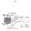
- the control device for fermenter according to the present invention controls the fermentation unit having a fermenter 1, which cultures the biomass under given conditions.
- the fermentation unit comprises the fermenter 1, a aerating unit 2, which supplies a oxygen gas into the fermenter 1, impellers 3, which stire the culture medium in the fermenter 1, a measurement unit 4, which measures the concentrations of oxygen, nutrients, biomass, or the like in the culture medium, a nutrient component feed unit 5, which supplies the nutrient components in the culture medium, and a drive control unit 6, which supplies drive control signals to the aerating unit 2, the impellers 3, and the nutrient component feed unit 5 in the fermenter 1.
- the control device comprises a mesh data generator 7, which generates mesh data for the fermenter 1 based on shape data on the fermenter 1, a processor 8, which executes computations in accordance with a running control program, memory 9, which stores the running control program, and an output display 10, which indicates the results of computations executed at the processor 8.
- the control device according to the present invention can be specifically implemented using hardware resources comprising an interface for entering data output from the measurement unit 4 of the fermenter 1, an input device for entering the shape data on the fermenter 1, or the like, the computation means such as a CPU, a memory means such as hard disk, nonvolatile memory, and volatile memory, and an displaying means such as a display.
- the control device according to the present invention may be implemented as an integrated type, which has been integrated in the fermenter unit. This means that the present invention may implement the fermentation unit having the control device for fermenter.
- the drive control unit 6, which is incorporated a PID (Proportional Integral Differential) control system, outputs the control signals based on target control values calculated by the processor 8 using, for example measured values input from the measurement unit 4 via the interface.
- PID Proportional Integral Differential
- the measurement unit 4 may measure, for example the concentration of the biomass contained in the culture medium sampled by a sampler, the components having positive effects on cell growth, and the components having negative effects on cell growth and also measure the concentrations of dissolved oxygen and dissolved carbon dioxide contained in the culture medium by a chromatographic system.
- the term "the components having positive effects on cell growth” described herein includes the nutrient components such as glucose and glutamic acid.
- the term "the components having negative effects on cell growth” described herein includes substances such as lactate and carbon dioxide produced in the culture process.
- the mesh data generator 7 enters data to be calculated by means of the input means so as to generate mesh data, and sends it to the processor 8.
- the term "the input data” described herein are the shape data such as the diameter and the height of the fermenter, the diameter width, and number of impellers of the fermenter; conditions such as an impeller rotation speed and a sparger gas flow rate; and initial values data such as the initial concentrations of culture medium components and biomass.
- the mesh data generated here may be output to the input data display unit, enabling the target to be analyzed to be checked as shown in FIGS. 2A and 2B.
- the processor 8 executes computations in accordance with the program stored in the memory 9.
- the program comprises the algorithm, which numerically, discretely, and algebraically integrates the time differential equation.
- ⁇ is the density (kg/m 3 ) of a fluid
- P pressure (Pa)
- g acceleration for gravity (m/s 2 )
- v t is an eddy viscosity coefficient (m 2 /s).
- bubbles are assumed to move at a flow rate ug(m/s) different from the flow rate of flow u f (m/s).
- u d is a bubble terminal velocity depending on a bubble diameter, which is often entered in the form of input data or a function formula being set the bubble diameter as a parameter.
- the flow rate of bubbles u g may be obtained by the dynamic equation similar to that in the formula (1); however, when the bubbles have any of smaller diameters, it is convenient to use the formula (7).
- the formulae (1) to (7) may be used to calculate the flow rate and gas holdup distributions in the fermenter.
- ⁇ is a specific growth rate (1/s) and Kd is a death rate (1/s).
- the transport equation of the medium component for example lactate (Lac) transported at the flow rate
- reaction dynamics model equations which describe growth, production, and consumption of the cells (formula (8)) and medium components (formulas (9) to (12)) through the process of metabolism.
- These reaction models are different depending on the type of a stem or cell line to be cultured.
- the models applicable to the general processes of mammalian cell culture are exemplified by the following formulae.
- q 02 is the oxygen uptake rate (mg/cell ⁇ s) per unit cell and q C02 is a carbon dioxide exhaust rate (mg/cell ⁇ s) per unit cell.
- the volumetric mass transfer coefficient k L a is obtained by multiplying a mass transfer coefficient velocity K L at the gas-liquid interface and a specific surface area a, which comprises of those at a bubble-liquid interface and at a gas-culture medium interface on the liquid free surface.
- a subscript b is used for that of the bubble-liquid interface and a subscript S is used for that of the liquid free surface.
- the gas holdup ratio number density ⁇ b is obtained by the aforementioned formula (6).
- S ⁇ is bubbles holdup blown from the sparger at an interval of unit time.
- the oxygen gas in the bubbles and on the liquid free surface dissolves into the liquid under the volumetric oxygen transfer coefficient K L,o,b a b or K L,o,s a s , and oxygen of q o2 per cell unit and per time unit are consumed by a cell.
- carbon dioxide of q co2 per cell unit and per time unit are exhausted from a cell, and transferred in the form of gas from the liquid into the bubbles and on the liquid free surface under the volumetric carbon dioxide transfer coefficient K L,co2, b a b and K L , co2 , s a s and finally purged out from the fermenter 1.
- the turbulent energy k and the turbulent energy dissipation rate ⁇ are calculated by the formulae (2) and (3) in the algorithm and thereby, they may be obtained at any point in any fermenter 1 only by means of computations with no experiment.
- volumetric mass transfer coefficients allows the fluid state in any shape of fermenter, as well as all the concentration distributions of the biomass metabolite, aerating gas, and dissolved gas to be obtained by means of computations and therefore, the shape and culture conditions of the fermenter 1 suitable for biomass culture may be known.
- the results of computations executed at the processor 8 are sent to the display unit 10 and displayed.
- the display unit 10 may display the results of computations in the form of distribution images and/or graphs.
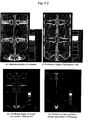
- the examples of distribution images are shown in FIGS.4-1A to 4-1D and FIGS.4-2A to 4-2H.
- FIG.4-1A shows an example of the displayed image of a flow rate vector
- FIG.4-1B shows an example of the displayed image of the gas holdup ratio
- FIG.4-1C shows an example of the displayed image of the distribution of the turbulent energy k
- FIG.4-ID shows an example of the displayed image of the distribution of the energy dissipation rate ⁇
- FIG.4-2E shows the displayed image of the distribution of the volumetric oxygen transfer coefficient Kla
- FIG.4-2F shows the displayed image of the Kolmogorov scale distribution
- FIG.4-2G shows an example of the displayed image of the oxygen concentration distribution
- FIG.4-2H shows an example of the displayed image of the carbon dioxide concentration distribution.
- FIGS.5A and 5B Examples of the displayed graphs are shown in FIGS.5A and 5B.
- FIG.5A shows an example of the displayed graph of the relationships between the impeller rotation speed, and turbulent energy k and the turbulent energy dissipation rate ⁇ .
- FIG5.B shows an example of the displayed graph of the relationship between the impeller rotation speed, and the total volumetric oxygen transfer coefficient Kla, the volumetric liquid-surface oxygen transfer coefficient Kla,s, and the volumetric bubble-oxygen transfer coefficient Kla,b.
- displaying the results of computation executed at the processor 8 may give quantitative information on the condition inside the fermenter 1.
- the turbulent energy k and the turbulent energy dissipation rate ⁇ take relatively larger values around the impellers and the volumetric oxygen transfer coefficient K L,o,b a b also takes a larger value as a function of these factors around the impellers.
- the volumetric oxygen transfer coefficient K L,o,b a b also takes a larger value as a function of these factors around the impellers.
- the differential equations describing the variations of the medium components over time in the aforementioned formulae (8) to (12) are modified to the differential equations suitable for different culture conditions. This means that it is preferable that the variations of the medium components over time depend on the cell line being cultured and the culture environment and thereby, the experimental constants are determined so that suitable differential equations may be established.
- the processor 8 processes time-series measured data sent from the measurement unit 4 equipped in the fermenter 1 to determine the experimental constants for the differential equations, which best reflect the time-series measured data.
- the component concentrations measured in the actual fermenter 1 generally can give only information on the averages of the components in the fermenter 1 and thereby, to obtain the detail spatial distributions, fluid dynamics calculations in the aforementioned formulae (1) to (7) are requisite. Accordingly, the differential equations given herein are assumed to describe the variations in spatial average concentrations of the medium components.
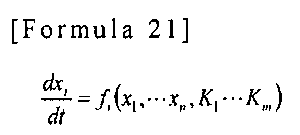
- the processor 8 takes differences between the calculated values for a historical curve of component concentration, which are obtained by numerically integrating the differential equations of the medium components and the values for a historical curve measured to determine the experimental constants, for which the differences between these values take the minimum values.
- This method may be applicable provided that the differential equation has been formulated with several experimental constants included and is not affected by the actual differential equation.
- a method, by which a Kalman filter is structured may be applied in sequentially obtaining the experimental constants. Using the experimental constants obtained in this way in executing the computations based on the aforementioned formulae (1) to (12), the results of computations approximate to the actual fermenter conditions may be obtained. This is useful in improving the accuracy of control of the fermenter.
- the processor 8 calculates the target value for control and the drive control unit 6 generates the drive control signals based on the target value for control.
- the drive control signals generated at the control device for fermenter according to the present invention control the aerating unit 2, the impeller 3, and the nutrient component feed unit 5 in the fermenter 1 to establish desired conditions in the fermenter 1.
- the amount of oxygen gas aerated into the fermenter 1 by controlling the aerating unit 2 is determined in the process described, below.
- the target value for control is calculated in terms of the preset target value for a concentration of dissolved oxygen in the following manner.
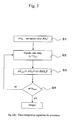
- the cell density Xa and agitation rotation speed rpm to increase the amount of aerating oxygen So are increased and the dissolved oxygen concentration Do that is obtained by integrating the differential equations, is a monotone increasing function of the amount of aerating oxygen So. Accordingly, using, for example, the regula falsi algorithm shown in FIG.6, the amount of aerating oxygen So may be obtained.
- the dissolved oxygen concentration Do in the fermenter 1 is calculated based on the differential equations in the formula (13) at the processor 8 (step 13).
- step 14 The calculated dissolved oxygen concentration Do and the target value entered at the step 10 are compared (step 14) and if the calculated dissolved oxygen concentration agrees with the target value, the processing is terminated. If the calculated dissolved oxygen concentration does not agree with the target value and exceeds it (step 15), the amount of aerating gas So is re-set to S max (step 16) and if the calculated dissolved oxygen concentration does not exceed the target value (step 15), the amount of aerating gas So is re-set to S min (step 16). Finally, the step 11 and subsequent steps are repeated until the measured dissolved oxygen concentration Do agrees with the target value entered in the step 10.
- a value suitable for the biomass to be cultured may be set.
- an increase in rotation speed of the impellers 3 brings an increase in turbulent energy k and turbulent energy dissipation rate ⁇ , which in turn, makes the volumetric oxygen transfer coefficient larger to facilitate dissolution of the oxygen gas into the culture medium.
- the target value for control over the agitation rotation speed may be set to the maximum rotation speed under the constraint of an agitation power.
- the target value for control over the agitation rotation speed should be determined based on two factors, namely cell death due to shear stress and accumulation of dissolved carbon dioxide.
- cell death due to shear stress a factor that causes cell death due to hydrodynamic shear stress. Therefore, running the impellers 3 at too high rotation speeds is not preferable in culturing the mammalian cells.
- all the flow rate gradients ⁇ ui/ ⁇ xj and the turbulent energy dissipation rates ⁇ may be numerically obtained and therefore, either value of ⁇ or ⁇ may be calculated at any point in the fermenter. By reference to the value, the probability of cell death may be estimated.
- FIG.4-2F The example of the displayed image of the Kolmogorov scale distribution calculated at the control device according to the present invention is shown in FIG.4-2F.
- FIG.7 An example of the displayed graph of the Kolmogorov scale using the rotation speed as a parameter is shown in FIG.7.
- the possibility of cell death depending on the agitation rotation speed of the impellers 3 may be estimated and the agitation rotation speed of the impellers 3 may be optimized.
- FIG.8 shows the dissolved carbon dioxide concentration in the fermenter 1 obtained by solving the differential equations using the rotation speed of the impellers 3 as a parameter under the fixed conditions of cell density Xa and the dissolved oxygen concentration Do. As known from FIG.8, when the rotation speed of the impellers 3 increases, the dissolved carbon dioxide concentration in the fermenter 1 reduces.
- the control device of the present invention allows the possibility of cell death depending on the agitation rotation speed of the impellers 3 to be estimated based on the graph shown in FIG.8 and the agitation rotation speed of the impellers 3 to be optimized.
- the rotation speed of the impellers 3, at which the dissolved carbon dioxide concentration is minimized under such a condition that cell death does not occur may be determined.
- the processor 8 determines the amount of aerating gas supplied into the fermenter 1 and the target value for control over the rotation speed of the impellers 3, as well as the target value for control over nutrient supply.
- the cells are continuously cultivated while the nutrient components consumed in the culture process are additionally supplied together with the fresh culture medium, which is called the Fed Batch method.
- the Fed Batch method the medium is continuously added with no medium extracted and thereby, the amount of liquid increases as the culture process advances.
- nutrient components the components positively involved in cell growth
- glucose, glutamine, amino acid, and serum are supplied. No medium is extracted and therefore, lactate and ammonia accumulate with no reduction in their amounts.
- the control device optimally controls the supply of the medium components such as glucose and glutamine.
- the processor 8 calculates the target value for control by means of dynamic programming shown in the following procedure using the differential equations in the aforementioned formulae (9) to (12).
- the calculated target value for control is input into the drive control unit 6.
- the drive control unit 6 generates the drive control signals based on the entered target value for control in order to control the supply of the medium components by the feed unit 5.
- F N ( x 0 ) Max v 0 ⁇ v N [ g ( x 0 , v 0 ) + g ( x 1 , v 1 ) + ⁇ + g ( x N , v N ) ] is defined.
- X 0 is an initial value for the state variable.
- the cell density is divided into 10 domain elements from 10 6 cells/mL to 10 7 cells/mL in increments of 10 6 cells/mL
- the concentration of lactate is divided into 10 domain elements from 0 to 1000 mg/L in increments of 100 mg/L
- the concentration of ammonia is divided into 10 domain elements from 0 to 100 mg/L in increments of 10 mg/L.
- x ⁇ ⁇ 3 i for each of domain elements is obtained by: [ Formula 35 ]
- F 0 ( x N ) Max v N ⁇ ⁇ j 2 [ g ( x N , v N ) ]
- V N ⁇ ⁇ 2 j which gives the maximum value
- v N which gives the maximum value
- v N v N (x N )
- F N (x 0 ) is the maximum variable for the target function.
- the target value for control used in controlling the amount of supplied medium components such as glucose and glutamine may be calculated by executing the aforementioned computation process at the processor 8.
- the target value for control calculated at the processor 8 is input into the drive control unit 6.
- the drive control signals are generated based on the input target value for control and the measured value read from the measurement unit 4 by for example, the PID control system.
- the drive control signals are output into the nutrient component feed unit 6 so as to control the amount of nutrient components supplied by the nutrient component feed unit 6. Accordingly, with the control device of the present invention, the fermenter may be driven under the condition where the biomass growth rate is maximized.
Landscapes
- Chemical & Material Sciences (AREA)
- Engineering & Computer Science (AREA)
- Wood Science & Technology (AREA)
- Health & Medical Sciences (AREA)
- Bioinformatics & Cheminformatics (AREA)
- Organic Chemistry (AREA)
- Life Sciences & Earth Sciences (AREA)
- Zoology (AREA)
- Analytical Chemistry (AREA)
- Biotechnology (AREA)
- Sustainable Development (AREA)
- Microbiology (AREA)
- Biochemistry (AREA)
- General Engineering & Computer Science (AREA)
- General Health & Medical Sciences (AREA)
- Genetics & Genomics (AREA)
- Biomedical Technology (AREA)
- Computer Hardware Design (AREA)
- Apparatus Associated With Microorganisms And Enzymes (AREA)
- Micro-Organisms Or Cultivation Processes Thereof (AREA)
Abstract
Description
- The present invention relates to a control device controlling a fermenter for culturing biomass such as mammalian cells or microorganisms.
- In an industrial culture, oxygen necessary for biomass to grow in a culture medium containing nutrient components such as glucose and glutamine is supplied in a form of a bubble aerating gas or supplied by aeration onto a liquid free surface while the culture medium is often frequently stirred to grow the biomass, harvesting a responsible material produced by the biomass. To successfully achieve biomass culture, it is required that inner fermenter conditions suitable for biomass culture be secured. In contrast, the structure and running conditions of the fermenter contribute to deviation from these suitable inner fermenter conditions.
- To ensure an increased volumetric mass transfer coefficient kLa for oxygen in the fermenter, and homogeneous mixture of the nutrient components and a dissolved oxygen concentration, the culture medium is stirred by impellers. Is difficult to achieve high kLa and sufficient homogeneity as for high-viscosity culture media. Though an attempt has been made to experimentally obtain the volumetric oxygen transfer coefficient kLa for each type of fermenter, in such an experimental method (
Japanese Patent Publication (Kokai) No. 2001-231544 Japanese Patent Publication (Kokai) No. 2001-75947 - Any starvation of nutrient components in the culture process inhibits growth of the biomass. In many cases, the components such a lactate, ammonia, and alcohol produced as by-products suppress the growth of the biomass, deteriorating the yield of responsible products. Accordingly, it is always important to measure the components in the culture medium and to sustain the nutrient components during fermenter's running. However, no satisfactory technique has been established for reflecting the measurement results in fermenter control. An attempt has been made to make a model of a biomass growing process by a differential equation of reaction dynamics, though no computer-aided control method, which combines both the techniques for modeling of the biomass growing process and achieving of hydrodynamic conditions in the fermenter, has been reported.
- To solve these problems, an object of the present invention is to provide the control device for fermenter, which is capable of producing the biomass and/or components produced by the biomass at a high yield by applying the fluid numerical simulation technique to reasonably find the running conditions suitable for the fermenter.
- The present invention, which has attained the abovementioned object, is composed of a plurality of the following means.
- The control device for fermenter according to the present invention comprises; an input means connected to the fermenter, in which biomass is cultured while oxygen gas is being blown into a culture medium and the culture medium is being stirred, for entering measured data output from a measurement means for measuring nutrient components, concentration of oxygen, concentration of carbon dioxide, and concentration of biomass in a medium; a computation means for calculating nutrient components uptake rate, oxygen uptake rate and carbon dioxide exhaust rate per unit amount of biomass from the measured data entered at the aforementioned input means, as well as volumetric mass transfer coefficient kLa from turbulent energy k and a turbulent energy dissipation rate e, both of which are calculated by a transport equation, as well as a diffusion coefficient D, followed by calculating the concentrations of the nutrient components, dissolved oxygen, and dissolved carbon dioxide in any area in the fermenter using an algorithm to numerically integrate a differential equation describing variations in medium components over time from the calculated nutrient components uptake rate, the calculated oxygen uptake rate, the calculated carbon dioxide exhaust rate, and the calculated volumetric mass transfer coefficient kLa; and a display means for displaying concentration distributions of the nutrient components, dissolved oxygen, and dissolved carbon dioxide in the fermenter based on the concentrations of the nutrient components, dissolved oxygen, and carbon dioxide in any area of the fermenter calculated at aforementioned computation means.
- According to the present invention, the variations of medium components over time and spatial distributions of the nutrient components in the fermenter are calculated by combining the differential equation describing the medium components with equations of fluid dynamics for numerical, discrete, and algebraic evaluation. This gives information on how the biomass grows in the any region in the fermenter and on what kind of fluid field is suitable for biomass growth. Moreover, the present invention provides the volumetric mass transfer coefficient kLa as a function kLa (k,ε,D) among k, ε, and the diffusion coefficient D based on the result of an experimental study on the relationship among a mass transfer coefficient for a turbulent field, and turbulent energy k and turbulent energy dissipation rate ε. This allows the volumetric mass transfer coefficient kLa for the any region in the fermenter of any structure to be calculated based only on the properties of the turbulent field and the values for gas properties without depending on the structure of the fermenter. Therefore, the concentrations of the aforementioned medium components, as well as of oxygen, carbon dioxide, and so on, can be calculated in the any point in the fermenter. Also, the structure of the fermenter suitable for biomass growth can be determined. Further, the present invention provides the nutrient supply algorithm based on time differential equations for the medium components by means of dynamic programming.
- The control device for the fermenter and a fermentation unit according to the present invention can display the distributions of dissolved oxygen concentration and dissolved carbon dioxide concentration on its display screen to facilitate the determination of conditions suitable for biomass growth in the fermenter.
-
- FIG.1 is a block diagram showing the structures of a control device for fermenter and a fermenter unit according to the present invention.
- FIG.2A and FIG. 2B show mesh data on the inside of the fermenter generated by a mesh data generator.
- FIG.3 is a flowchart explaining an algorithm for sequentially, numerically, discretely, and algebraically integrating the differential equations for time.
- FIGS.4-1A, 4-1B, 4-1C, and 4-1D show an example of the results of computations indicated on a display, in which FIG.4-1A is an example of the displayed flow rate vector; FIG.4-1B is an example of the displayed gas holdup ratio, FIG.4-1C is an example of the displayed distribution of turbulent energy k, and FIG.4-ID is an example of the displayed distribution of turbulent energy dissipation rate ε.
- FIGS.4-2E, 4-2F, 4-2G, and 4-2H show an example of the results of computations indicated on the display; in which FIG4-2E is an example of the displayed distribution of volumetric oxygen transfer coefficient KLa, FIG.4-2F is an example of the displayed distribution of Kolmogorov scale, FIG4-2G is an example of the displayed image of the oxygen concentration distribution, and FIG.4-2H is an example of the displayed image of the carbon dioxide concentration distribution.
- FIGS.5A and FIG. 5B show an example of a graph of the result of computations indicated on the display; in which FIG.5A is an example of the displayed graph of the relationship between the rotation speed of impellers; and the turbulent energy k and the turbulent energy dissipation rate ε, and FIG. 5B is an example of a graph of the relationship between the rotation speed of the impellers; and the total volumetric oxygen transfer coefficient Kla, the volumetric liquid-surface oxygen transfer coefficient Kla,s, and the volumetric bubble-oxygen transfer coefficient Kla,b.
- FIG.6 is a flowchart explaining a regula falsi algorithm for obtaining the amount of aerating oxygen.
- FIG.7 is a Kolmogorov's characteristic diagram being set the rotation speed as a parameter.
- FIG.8 is a characteristic diagram showing the dissolved carbon dioxide concentration in the fermenter calculated by evaluating the differential equations being set the rotation speed of the
impellers 3 as a parameter under the condition where the cell density Xa and the dissolved oxygen concentration Do are fixed. - Now, by reference to the drawings, the control device for fermenter according to the present invention is described in detail. As shown in FIG.1, the control device for fermenter according to the present invention controls the fermentation unit having a
fermenter 1, which cultures the biomass under given conditions. The fermentation unit comprises thefermenter 1, aaerating unit 2, which supplies a oxygen gas into thefermenter 1,impellers 3, which stire the culture medium in thefermenter 1, a measurement unit 4, which measures the concentrations of oxygen, nutrients, biomass, or the like in the culture medium, a nutrientcomponent feed unit 5, which supplies the nutrient components in the culture medium, and adrive control unit 6, which supplies drive control signals to theaerating unit 2, theimpellers 3, and the nutrientcomponent feed unit 5 in thefermenter 1. - As shown in FIG. 1, the control device according to the present invention comprises a
mesh data generator 7, which generates mesh data for thefermenter 1 based on shape data on thefermenter 1, a processor 8, which executes computations in accordance with a running control program, memory 9, which stores the running control program, and anoutput display 10, which indicates the results of computations executed at the processor 8. The control device according to the present invention can be specifically implemented using hardware resources comprising an interface for entering data output from the measurement unit 4 of thefermenter 1, an input device for entering the shape data on thefermenter 1, or the like, the computation means such as a CPU, a memory means such as hard disk, nonvolatile memory, and volatile memory, and an displaying means such as a display. Alternatively, the control device according to the present invention may be implemented as an integrated type, which has been integrated in the fermenter unit. This means that the present invention may implement the fermentation unit having the control device for fermenter. - The
drive control unit 6, which is incorporated a PID (Proportional Integral Differential) control system, outputs the control signals based on target control values calculated by the processor 8 using, for example measured values input from the measurement unit 4 via the interface. - The measurement unit 4 may measure, for example the concentration of the biomass contained in the culture medium sampled by a sampler, the components having positive effects on cell growth, and the components having negative effects on cell growth and also measure the concentrations of dissolved oxygen and dissolved carbon dioxide contained in the culture medium by a chromatographic system. The term "the components having positive effects on cell growth" described herein includes the nutrient components such as glucose and glutamic acid. The term "the components having negative effects on cell growth" described herein includes substances such as lactate and carbon dioxide produced in the culture process.
- The
mesh data generator 7 enters data to be calculated by means of the input means so as to generate mesh data, and sends it to the processor 8. The term "the input data" described herein are the shape data such as the diameter and the height of the fermenter, the diameter width, and number of impellers of the fermenter; conditions such as an impeller rotation speed and a sparger gas flow rate; and initial values data such as the initial concentrations of culture medium components and biomass. The mesh data generated here may be output to the input data display unit, enabling the target to be analyzed to be checked as shown in FIGS. 2A and 2B. - The processor 8 executes computations in accordance with the program stored in the memory 9. As shown in FIG.3, the program comprises the algorithm, which numerically, discretely, and algebraically integrates the time differential equation. In other words, the program comprises a
step 1, at which t is initialized to to; astep 2, at which a time step is updated to tn+1; astep 3, at which A(tn+1) = A(tn)+Δt·f(A(tn)) is calculated; and a step 4, at which n = nmax is determined. - Here, the differential equation n to be integrated at the processor 8 herein is an equation of motion (Navie-Stokes equation) for a flow rate of flow uf(m/s), which may be represented by:

- The differential equations integrated at the processor 8 are the transport equation of turbulent energy k(m2/s2) represented by:


- A gas holdup ratio αb in the culture medium is calculated by:


- The transport equation of cell density (Xa)(cells/mL) of the cells transported at a flow rate uf, which is integrated at the processor 8, is represented by:


- In formulae (8) to (12), the right sides are reaction dynamics model equations, which describe growth, production, and consumption of the cells (formula (8)) and medium components (formulas (9) to (12)) through the process of metabolism. These reaction models are different depending on the type of a stem or cell line to be cultured. The models applicable to the general processes of mammalian cell culture are exemplified by the following formulae.
- In the formulae (8) to (12), the reaction equations extracted only for mammalian cells are represented by:


In addition,
- The transport equation for the dissolved oxygen calculated at the processor 8 is represented by:


- In the aforementioned formula,


fermenter 1. - Each of mass transfer velocities KL,i,j (i =O,CO2, j=b,S) described herein is given as a function of only the turbulent energy k, the turbulent energy dissipation rate ε, and the diffusion coefficient Di (i =O, CO2) that is a property value, and does not depend directly on the size of the
fermenter 1, the bubble diameter, and so on. The turbulent energy k and the turbulent energy dissipation rate ε are calculated by the formulae (2) and (3) in the algorithm and thereby, they may be obtained at any point in anyfermenter 1 only by means of computations with no experiment. - According to the present invention, the use of these volumetric mass transfer coefficients allows the fluid state in any shape of fermenter, as well as all the concentration distributions of the biomass metabolite, aerating gas, and dissolved gas to be obtained by means of computations and therefore, the shape and culture conditions of the
fermenter 1 suitable for biomass culture may be known. - The results of computations executed at the processor 8 are sent to the
display unit 10 and displayed. Thedisplay unit 10 may display the results of computations in the form of distribution images and/or graphs. The examples of distribution images are shown in FIGS.4-1A to 4-1D and FIGS.4-2A to 4-2H. FIG.4-1A shows an example of the displayed image of a flow rate vector, FIG.4-1B shows an example of the displayed image of the gas holdup ratio, FIG.4-1C shows an example of the displayed image of the distribution of the turbulent energy k, FIG.4-ID shows an example of the displayed image of the distribution of the energy dissipation rate ε, FIG.4-2E shows the displayed image of the distribution of the volumetric oxygen transfer coefficient Kla, FIG.4-2F shows the displayed image of the Kolmogorov scale distribution, FIG.4-2G shows an example of the displayed image of the oxygen concentration distribution, and FIG.4-2H shows an example of the displayed image of the carbon dioxide concentration distribution. - Examples of the displayed graphs are shown in FIGS.5A and 5B. FIG.5A shows an example of the displayed graph of the relationships between the impeller rotation speed, and turbulent energy k and the turbulent energy dissipation rate ε. FIG5.B shows an example of the displayed graph of the relationship between the impeller rotation speed, and the total volumetric oxygen transfer coefficient Kla, the volumetric liquid-surface oxygen transfer coefficient Kla,s, and the volumetric bubble-oxygen transfer coefficient Kla,b.
- Thus, according to the control device for fermenter of the present invention, displaying the results of computation executed at the processor 8 may give quantitative information on the condition inside the
fermenter 1. For example, as shown in FIGS.4-1 and 4-2, it is clear that according to the control device for fermenter of the present invention, the turbulent energy k and the turbulent energy dissipation rate ε take relatively larger values around the impellers and the volumetric oxygen transfer coefficient KL,o,bab also takes a larger value as a function of these factors around the impellers. As known from FIG. 5A, as the impeller rotation speed increases, the flow rate in the fermenter becomes higher and k and ε increase accordingly, while the turbulent energy k increases in proportion to the square value for the rotation speed and the turbulent energy dissipation rate ε increases in proportion to the cubic value for the rotation speed. As shown in FIG.5B, regarding the volumetric oxygen transfer coefficient, the dependency of KL,o,bab for bubbles and KL,o,sas for the liquid surface on the rotation speed is different. This is because the dependency of average k and ε values in thefermenter 1 on the rotation speed is different from the dependency of k and ε values in the vicinity of the liquid free surface on the rotation speed. - According to the control device for fermenter of the present invention, it is preferable that the differential equations describing the variations of the medium components over time in the aforementioned formulae (8) to (12) are modified to the differential equations suitable for different culture conditions. This means that it is preferable that the variations of the medium components over time depend on the cell line being cultured and the culture environment and thereby, the experimental constants are determined so that suitable differential equations may be established.
- To achieve this, the processor 8 processes time-series measured data sent from the measurement unit 4 equipped in the
fermenter 1 to determine the experimental constants for the differential equations, which best reflect the time-series measured data. In this case, it is assumed that no spatial distribution is included in the experimental constants for the differential equations. The component concentrations measured in theactual fermenter 1 generally can give only information on the averages of the components in thefermenter 1 and thereby, to obtain the detail spatial distributions, fluid dynamics calculations in the aforementioned formulae (1) to (7) are requisite. Accordingly, the differential equations given herein are assumed to describe the variations in spatial average concentrations of the medium components. - Specifically, the processor 8 takes differences between the calculated values for a historical curve of component concentration, which are obtained by numerically integrating the differential equations of the medium components and the values for a historical curve measured to determine the experimental constants, for which the differences between these values take the minimum values. For example, assuming that a set of components in the aforementioned formulae (8) to (12) is Xi (I = cell density, glucose, glutamine, lactate, ammonia) and a set of experimental constants is Kj (j = 1,m), a set of the differential equations may be formally represented by:


- It is preferable that in the control device for fermenter according to the present invention, the processor 8 calculates the target value for control and the
drive control unit 6 generates the drive control signals based on the target value for control. The drive control signals generated at the control device for fermenter according to the present invention control the aeratingunit 2, theimpeller 3, and the nutrientcomponent feed unit 5 in thefermenter 1 to establish desired conditions in thefermenter 1. - The amount of oxygen gas aerated into the
fermenter 1 by controlling the aeratingunit 2 is determined in the process described, below. - First of all, the target value for control is calculated in terms of the preset target value for a concentration of dissolved oxygen in the following manner. When the cell density Xa and agitation rotation speed rpm to increase the amount of aerating oxygen So are increased and the dissolved oxygen concentration Do that is obtained by integrating the differential equations, is a monotone increasing function of the amount of aerating oxygen So. Accordingly, using, for example, the regula falsi algorithm shown in FIG.6, the amount of aerating oxygen So may be obtained. This means that the operator: enters the amount of biomass (X), the rotation speed (rpm) of the
impellers 3, and the target value for dissolved oxygen concentration (Do) at the input unit (step 10); reads the preset the maximum amount of aerating gas Smax (e.g., Smax = 1018) and specifies the minimum amount of aerating gas Smin (e.g., Smin= 0) (step 11); and sets the amount of aerating gas So (e.g., So = (Smax + Smin)/2) (step 12). Next, the dissolved oxygen concentration Do in thefermenter 1 is calculated based on the differential equations in the formula (13) at the processor 8 (step 13). Next, The calculated dissolved oxygen concentration Do and the target value entered at thestep 10 are compared (step 14) and if the calculated dissolved oxygen concentration agrees with the target value, the processing is terminated. If the calculated dissolved oxygen concentration does not agree with the target value and exceeds it (step 15), the amount of aerating gas So is re-set to Smax (step 16) and if the calculated dissolved oxygen concentration does not exceed the target value (step 15), the amount of aerating gas So is re-set to Smin (step 16). Finally, thestep 11 and subsequent steps are repeated until the measured dissolved oxygen concentration Do agrees with the target value entered in thestep 10. - For the agitation rotation speed of the
impellers 3, a value suitable for the biomass to be cultured may be set. Generally, an increase in rotation speed of theimpellers 3 brings an increase in turbulent energy k and turbulent energy dissipation rate ε, which in turn, makes the volumetric oxygen transfer coefficient larger to facilitate dissolution of the oxygen gas into the culture medium. Accordingly, for example, in culturing microorganisms, the target value for control over the agitation rotation speed may be set to the maximum rotation speed under the constraint of an agitation power. - On the other hand, in culturing mammalian cells, the target value for control over the agitation rotation speed should be determined based on two factors, namely cell death due to shear stress and accumulation of dissolved carbon dioxide. When an increase in agitation rotation speed results in the increased flow rate in the
fermenter 1, some of the cells come to death due to hydrodynamic shear stress. Therefore, running theimpellers 3 at too high rotation speeds is not preferable in culturing the mammalian cells. The shear rate γ of the flow represented by;

- The example of the displayed image of the Kolmogorov scale distribution calculated at the control device according to the present invention is shown in FIG.4-2F. An example of the displayed graph of the Kolmogorov scale using the rotation speed as a parameter is shown in FIG.7. With the control device according to the present invention, based on the graph shown in FIG.7, the possibility of cell death depending on the agitation rotation speed of the
impellers 3 may be estimated and the agitation rotation speed of theimpellers 3 may be optimized. - The agitation rotation speed of the
impellers 3 affects the dissolved carbon dioxide concentration in the culture medium. If the dissolved carbon dioxide concentration in the culture medium increases, the growth rate of cells deteriorates. FIG.8 shows the dissolved carbon dioxide concentration in thefermenter 1 obtained by solving the differential equations using the rotation speed of theimpellers 3 as a parameter under the fixed conditions of cell density Xa and the dissolved oxygen concentration Do. As known from FIG.8, when the rotation speed of theimpellers 3 increases, the dissolved carbon dioxide concentration in thefermenter 1 reduces. This is because that with the increased rotation speed, the volumetric carbon dioxide transfer coefficient in the bubbles or on the liquid free surface becomes large and thereby, the speeds of transforming the dissolved carbon dioxide from the biomass transforms into the liquid phase, and purging the dissolved carbon dioxide from thefermenter 1 through the liquid free surface increase. The control device of the present invention allows the possibility of cell death depending on the agitation rotation speed of theimpellers 3 to be estimated based on the graph shown in FIG.8 and the agitation rotation speed of theimpellers 3 to be optimized. - Based on the graph illustrating the Kolmogorov scale shown in FIG.7 and the graph illustrating the dissolved carbon dioxide concentration shown in FIG.8, the rotation speed of the
impellers 3, at which the dissolved carbon dioxide concentration is minimized under such a condition that cell death does not occur, may be determined. - In addition, the processor 8 according to the present invention determines the amount of aerating gas supplied into the
fermenter 1 and the target value for control over the rotation speed of theimpellers 3, as well as the target value for control over nutrient supply. Under control over nutrient supply, the cells are continuously cultivated while the nutrient components consumed in the culture process are additionally supplied together with the fresh culture medium, which is called the Fed Batch method. In the Fed Batch method, the medium is continuously added with no medium extracted and thereby, the amount of liquid increases as the culture process advances. In culturing the mammalian cells, such nutrient components (the components positively involved in cell growth) as glucose, glutamine, amino acid, and serum are supplied. No medium is extracted and therefore, lactate and ammonia accumulate with no reduction in their amounts. - Focusing on the differential equations describing the variations in the medium components over time shown in the aforementioned formulae (9) to (12), the following quantitative information may be given. Decreases in glucose and glutamine reduce the cell growth rate, inhibiting an increase in cell count. Assuming that the yield of the product is proportional to the cell count, it is considered that supplying sufficient amounts of glucose and glutamine increases the yield of the product. On the other hand, focusing on the differential equations describing the variations in lactate and ammonia over time, it is considered that increases in glucose and glutamine make the lactate and ammonia concentrations higher, while increases in lactate and ammonia (the components negatively involved in cell growth) inhibit the cell growth rate. Accordingly, it is possible that at any optimal concentrations of glutamine and glucose, the cell count and the yield of the product are maximized. It is preferable that the control device according to the present invention optimally controls the supply of the medium components such as glucose and glutamine. Specifically, the processor 8 calculates the target value for control by means of dynamic programming shown in the following procedure using the differential equations in the aforementioned formulae (9) to (12). The calculated target value for control is input into the
drive control unit 6. Thedrive control unit 6 generates the drive control signals based on the entered target value for control in order to control the supply of the medium components by thefeed unit 5. - First of all, assuming that a set of cell density, lactate and ammonia (the components negatively involved in cell growth) is a state variable when the differential equations in the formulae (9) to (12) are given,


- When the aforementioned recursive expression is used, an arithmetic algorithm for dynamic programming behaves as described below. It is assumed that a domain, in which the state variable X may take a value, is x ∈ Ω3 and a domain, in which the control variable V may take a value, is V ∈ Λ2. To execute numeric calculations, the domain Ω3 for the state variable and the domain Λ2 for the control variable are made discrete as long as the memory capacity of a computer accepts. Specifically, this means that for example, the cell density is divided into 10 domain elements from 106 cells/mL to 107 cells/mL in increments of 106 cells/mL, the concentration of lactate is divided into 10 domain elements from 0 to 1000 mg/L in increments of 100 mg/L, and the concentration of ammonia is divided into 10 domain elements from 0 to 100 mg/L in increments of 10 mg/L. Accordingly, the domain Ω3 is divided into 1000 domain elements Ω3 i (I = 1, ..., 1000). Similarly, assuming that for example, the concentration of glucose is divided into 10 domain elements from 0 to 2000 mg/L and the concentration of glutamine is divided into 10 domain elements from 0 to 1000 mg/L, the domain Λ2 for the control variable is divided into 100 domain elements Λ2 j(j = 1, ..., 100).
- First of all, x ∈ Ω3 i for each of domain elements is obtained by:

- Next, for each xN-1 ∈ Ω3 i,


- vn = v(xn) [n = 0, 1, ..., N] stored in memory through the aforementioned computation process is the target control, Xn [n = 0, 1, ..., N] is a trajectory drawn by the state variable, and FN(x0) is the maximum variable for the target function. In culturing cells, if a culture period is approximately 10 days and 24 hours/day are divided into 10 time elements, the time axis division number N is 100 and if a domain Ω3 for the state variable is divided into 1000 domain elements, 105 array variables are required to store each Vn = v(xn) [n = 1, ..., N], which is the target control in the aforementioned computation process. This requires a huge amount of memory capacity, however, the current computer sufficiently addresses this requirement of memory capacity.
- At the control device according to the present invention, the target value for control used in controlling the amount of supplied medium components such as glucose and glutamine may be calculated by executing the aforementioned computation process at the processor 8. The target value for control calculated at the processor 8 is input into the
drive control unit 6. At thedrive control unit 6, the drive control signals are generated based on the input target value for control and the measured value read from the measurement unit 4 by for example, the PID control system. The drive control signals are output into the nutrientcomponent feed unit 6 so as to control the amount of nutrient components supplied by the nutrientcomponent feed unit 6. Accordingly, with the control device of the present invention, the fermenter may be driven under the condition where the biomass growth rate is maximized.
Claims (10)
- A control device for fermenter comprising:an input means connected to the fermenter, in which biomass is cultured while oxygen gas is being blown into a culture medium and the culture medium is being stirred, for entering measured data output from a measurement means for measuring nutrient components, concentration of oxygen, concentration of carbon dioxide, and concentration of biomass in a medium;a computation means for calculating nutrient components uptake rate, oxygen uptake rate and carbon dioxide exhaust rate per unit amount of biomass from the measured data entered at the aforementioned input means, as well as volumetric mass transfer coefficient kLa from turbulent energy k and a turbulent energy dissipation rate e, both of which are calculated by a transport equation, as well as a diffusion coefficient D, followed by calculating the concentrations of the nutrient components, dissolved oxygen, and dissolved carbon dioxide in any area in the fermenter using an algorithm to numerically integrate a differential equation describing variations in medium components over time from the calculated nutrient components uptake rate, the calculated oxygen uptake rate, the calculated carbon dioxide exhaust rate, and the calculated volumetric mass transfer coefficient kLa; anda display means for displaying concentration distributions of the nutrient components, dissolved oxygen, and dissolved carbon dioxide in the fermenter based on the concentrations of the nutrient components, dissolved oxygen, and carbon dioxide in any area of the fermenter calculated at aforementioned computation means.
- The control device for fermenter according to claim 1, wherein the aforementioned computation means compares the calculated dissolved oxygen concentration and a preset targeted value for dissolved oxygen concentration so as to generate a control signal for controlling the amount of oxygen gas to be supplied to the fermenter.
- The control device for fermenter according to claim 1, wherein the aforementioned computation means calculates a value for an indicator of biomass death so as to generate a control signal for controlling a rotation speed of impellers in the fermenter.
- The control device for fermenter according to claim 1, wherein the aforementioned differential equation contains experimental constants and the aforementioned computation means calculates the aforementioned experimental constants so that the measured data entered at the aforementioned input means corresponds to data on the measured value obtained by numerically integrating the aforementioned differential equation by a least squares method to re-establish the aforementioned differential equation.
- The control device for fermenter according to claim 1, wherein the aforementioned input means enters measured data on biomass concentration, components having positive effects on biomass concentration, and components having negative effects on cell growth, wherein when a formula calculating an yield of a product to be harvested is a target function, a concentration of the component having negative effects on cell density and cell growth is a state variable, and a concentration of the component having positive effects on cell growth is a control variable, the aforementioned computation means divides variance ranges of the state variable and the control variable into a finite number of partial regions, respectively, so as to generate control signals for time series supply of the components having positive effects on cell growth such that the target function can be maximized using dynamic programming.
- A fermentation unit comprising:a fermenter, in which biomass is cultured while oxygen gas is being blown into a culture medium and the culture medium is being stirred;a measurement means connected to the aforementioned fermenter for measuring nutrient components, concentration of oxygen, concentration of carbon dioxide, and concentration of biomass in a medium in the fermenter;an input means for entering measured data regarding at least nutrient components, concentration of oxygen, concentration of carbon dioxide, and concentration of biomass in a medium in the fermenter, which are measured at the aforementioned measurement meansa computation means for calculating nutrient components uptake rate, oxygen uptake rate and carbon dioxide exhaust rate per unit amount of biomass from the measured data entered at the aforementioned input means, as well as volumetric mass transfer coefficient kLa from turbulent energy k and a turbulent energy dissipation rate e, both of which are calculated by a transport equation, as well as a diffusion coefficient D, followed by calculating the concentrations of the nutrient components, dissolved oxygen, and dissolved carbon dioxide in any area in the fermenter using an algorithm to numerically integrate a differential equation describing variations in medium components over time from the calculated nutrient components uptake rate, the calculated oxygen uptake rate, the calculated carbon dioxide exhaust rate, and the calculated volumetric mass transfer coefficient kLa; anda display means for displaying concentration distributions of the nutrient components, dissolved oxygen, and dissolved carbon dioxide in the fermenter based on the concentrations of the nutrient components, dissolved oxygen, and carbon dioxide in any area of the fermenter calculated at aforementioned computation means.
- The fermentation unit according to claim 6, further comprising: an oxygen gas feed unit for feeding an oxygen gas into the fermenter based on a control signal,
wherein the control signal is calculated by comparing the dissolved oxygen concentration that are calculated by the aforementioned computation means and a preset targeted value for dissolved oxygen concentration at the aforementioned computation means and the the control signal controls the amount of oxygen gas to be supplied into the fermenter. - The fermentation unit according to claim 6, wherein, the value for the indicator of biomass death is calculated at the aforementioned computation means and the rotation speed of the impellers in the fermenter is controlled based on the control signal generated at the aforementioned computation means.
- The fermentation unit according to claim 6, wherein the aforementioned differential equation contains experimental constants and the aforementioned computation means calculates the aforementioned experimental constants so that the measured data entered at the aforementioned input means corresponds to data on the measured value obtained by numerically integrating the aforementioned differential equation by a least squares method to re-establish the aforementioned differential equation.
- The fermentation unit according to claim 6, further comprising:a feed unit for supplying the components having positive effects on cell growth in the fermenter,wherein the aforementioned measurement means measures a data on biomass concentration, components having positive effects on cell growth, and components having negative effects on cell growth,
wherein when a formula calculating an yield of a product to be harvested is a target function, a concentration of the component having negative effects on cell density and cell growth is a state variable, and a concentration of the component having positive effects on cell growth is a control variable, the aforementioned computation means divides variance ranges of the state variable and the control variable into a finite number of partial regions, respectively, so as to generate control signals for time series supply of the components having positive effects on cell growth such that the target function can be maximized using dynamic programming, and
wherein the feed unit supplies the components having positive effects on cell growth in the fermenter based on the control signals for time series supply.
Applications Claiming Priority (1)
| Application Number | Priority Date | Filing Date | Title |
|---|---|---|---|
| JP2005086415 | 2005-03-24 |
Publications (1)
| Publication Number | Publication Date |
|---|---|
| EP1705243A1 true EP1705243A1 (en) | 2006-09-27 |
Family
ID=36658739
Family Applications (1)
| Application Number | Title | Priority Date | Filing Date |
|---|---|---|---|
| EP06003435A Withdrawn EP1705243A1 (en) | 2005-03-24 | 2006-02-20 | Control device for fermenter |
Country Status (2)
| Country | Link |
|---|---|
| US (1) | US7771988B2 (en) |
| EP (1) | EP1705243A1 (en) |
Cited By (4)
| Publication number | Priority date | Publication date | Assignee | Title |
|---|---|---|---|---|
| WO2020136362A1 (en) * | 2018-12-28 | 2020-07-02 | Centre National De La Recherche Scientifique | Fluidic system for producing extracellular vesicles and associated method |
| WO2020136361A1 (en) * | 2018-12-28 | 2020-07-02 | Centre National De La Recherche Scientifique | Fluidic system for producing extracellular vesicles comprising a therapeutic or imaging agent and associated method |
| US20230348837A1 (en) * | 2021-08-17 | 2023-11-02 | Jgc Japan Corporation | Calculation device, control device, culture system, and method for designing culture system |
| CN119931817A (en) * | 2025-01-20 | 2025-05-06 | 山东协和学院 | Dynamic fermentation tank control system for the production of diabetic intestinal microecological regulation preparations |
Families Citing this family (28)
| Publication number | Priority date | Publication date | Assignee | Title |
|---|---|---|---|---|
| US7444197B2 (en) | 2004-05-06 | 2008-10-28 | Smp Logic Systems Llc | Methods, systems, and software program for validation and monitoring of pharmaceutical manufacturing processes |
| US7799273B2 (en) | 2004-05-06 | 2010-09-21 | Smp Logic Systems Llc | Manufacturing execution system for validation, quality and risk assessment and monitoring of pharmaceutical manufacturing processes |
| US8634940B2 (en) * | 2006-10-31 | 2014-01-21 | Rockwell Automation Technologies, Inc. | Model predictive control of a fermentation feed in biofuel production |
| WO2009129655A1 (en) * | 2008-04-23 | 2009-10-29 | 西门子公司 | A fermentation control method and a fermentation control system |
| CN101981207B (en) * | 2008-04-23 | 2013-06-19 | 西门子公司 | Method and device for controlling fermenting process |
| JP4883067B2 (en) | 2008-09-29 | 2012-02-22 | 株式会社日立プラントテクノロジー | Culture apparatus and culture method |
| US20120258441A1 (en) * | 2009-12-22 | 2012-10-11 | Ge Healthcare Bio-Sciences Ab | Method for controlling culture parameters in a bioreactor |
| US11773358B2 (en) | 2009-12-22 | 2023-10-03 | Cytiva Sweden Ab | Method for controlling culture parameters in a bioreactor |
| US9681644B2 (en) * | 2010-02-25 | 2017-06-20 | Timberfish, Llc | Process and method for optimizing production of food and feed |
| US20120156669A1 (en) | 2010-05-20 | 2012-06-21 | Pond Biofuels Inc. | Biomass Production |
| US8940520B2 (en) | 2010-05-20 | 2015-01-27 | Pond Biofuels Inc. | Process for growing biomass by modulating inputs to reaction zone based on changes to exhaust supply |
| US11512278B2 (en) | 2010-05-20 | 2022-11-29 | Pond Technologies Inc. | Biomass production |
| US8889400B2 (en) | 2010-05-20 | 2014-11-18 | Pond Biofuels Inc. | Diluting exhaust gas being supplied to bioreactor |
| US8969067B2 (en) | 2010-05-20 | 2015-03-03 | Pond Biofuels Inc. | Process for growing biomass by modulating supply of gas to reaction zone |
| US20120276633A1 (en) | 2011-04-27 | 2012-11-01 | Pond Biofuels Inc. | Supplying treated exhaust gases for effecting growth of phototrophic biomass |
| US9534261B2 (en) | 2012-10-24 | 2017-01-03 | Pond Biofuels Inc. | Recovering off-gas from photobioreactor |
| JP5913084B2 (en) * | 2012-12-26 | 2016-04-27 | 株式会社日立製作所 | CULTURE CONTROL METHOD, CELL CULTURE DEVICE, AND CELL CHARACTERISTICS EVALUATION DEVICE |
| JP6893208B2 (en) * | 2015-10-30 | 2021-06-23 | エフ.ホフマン−ラ ロシュ アーゲーF. Hoffmann−La Roche Aktiengesellschaft | Identification of calibration deviation of PH measuring device |
| ES3063930T3 (en) | 2017-07-07 | 2026-04-21 | Univ Kyoto | Platelet production method and apparatus and method for determining operating conditions in platelet production apparatus |
| EP3688133B1 (en) | 2017-09-29 | 2022-11-23 | Unibio A/S | Optimization of fermentation processes |
| JP2022551049A (en) * | 2019-10-11 | 2022-12-07 | サイティバ・スウェーデン・アクチボラグ | Bioreactor device and method of operation |
| CN112940919A (en) * | 2019-12-10 | 2021-06-11 | 中国科学院大连化学物理研究所 | Fermentation process multi-parameter on-line monitoring device |
| US20230374439A1 (en) * | 2020-09-25 | 2023-11-23 | Resonac Corporation | Cell culture apparatus and method for producing cell groups |
| CN115011458A (en) * | 2022-06-08 | 2022-09-06 | 上海履济技术服务中心 | A kind of automatic control device for substrate replenishment rate in fermentation process |
| CN116894177B (en) * | 2023-07-28 | 2025-12-02 | 安及义实业(上海)有限公司 | Monitoring methods, devices, computer equipment, and storage media for fermentation equipment |
| CN119806262B (en) * | 2025-03-13 | 2025-06-13 | 贵州大学 | A straw feed fermentation processing control system and method |
| CN120699736B (en) * | 2025-06-03 | 2026-03-31 | 金华利家园生物工程有限公司 | An E. coli fermenter capable of stably measuring carbon dioxide concentration |
| CN121610351B (en) * | 2026-02-03 | 2026-04-17 | 贵州食品工程职业学院 | Fermentation monitoring and early warning system and method |
Citations (2)
| Publication number | Priority date | Publication date | Assignee | Title |
|---|---|---|---|---|
| JP2001075947A (en) * | 1999-09-01 | 2001-03-23 | Hitachi Ltd | Aeration stirring tank |
| JP2001231544A (en) * | 2000-02-24 | 2001-08-28 | Hitachi Ltd | Operation control method of aeration stirred culture tank |
Family Cites Families (4)
| Publication number | Priority date | Publication date | Assignee | Title |
|---|---|---|---|---|
| US4064015A (en) * | 1975-05-12 | 1977-12-20 | New Brunswick Scientific Co., Inc. | Control of biosynthesis in submerged culture |
| JPH06153909A (en) | 1992-11-16 | 1994-06-03 | Sumitomo Heavy Ind Ltd | Method for controlling fermentation |
| JPH07313190A (en) | 1994-03-30 | 1995-12-05 | Kao Corp | Substrate concentration estimation method in culture solution |
| JP2003141187A (en) * | 2001-11-07 | 2003-05-16 | Furukawa Electric Co Ltd:The | Analysis grid data generation device, analysis grid data generation method, and program for causing computer to execute the method |
-
2006
- 2006-02-17 US US11/355,954 patent/US7771988B2/en not_active Expired - Fee Related
- 2006-02-20 EP EP06003435A patent/EP1705243A1/en not_active Withdrawn
Patent Citations (2)
| Publication number | Priority date | Publication date | Assignee | Title |
|---|---|---|---|---|
| JP2001075947A (en) * | 1999-09-01 | 2001-03-23 | Hitachi Ltd | Aeration stirring tank |
| JP2001231544A (en) * | 2000-02-24 | 2001-08-28 | Hitachi Ltd | Operation control method of aeration stirred culture tank |
Non-Patent Citations (3)
| Title |
|---|
| LANGHEINRICH ET AL.: "Oxygen transfer in stirred bioreactors under animal cell culture conditions", TRANS ICHEME, vol. 80, 2002, pages 39 - 44, XP008066855 * |
| PATENT ABSTRACTS OF JAPAN vol. 2000, no. 20 10 July 2001 (2001-07-10) * |
| PATENT ABSTRACTS OF JAPAN vol. 2000, no. 25 12 April 2001 (2001-04-12) * |
Cited By (7)
| Publication number | Priority date | Publication date | Assignee | Title |
|---|---|---|---|---|
| WO2020136362A1 (en) * | 2018-12-28 | 2020-07-02 | Centre National De La Recherche Scientifique | Fluidic system for producing extracellular vesicles and associated method |
| WO2020136361A1 (en) * | 2018-12-28 | 2020-07-02 | Centre National De La Recherche Scientifique | Fluidic system for producing extracellular vesicles comprising a therapeutic or imaging agent and associated method |
| FR3091296A1 (en) * | 2018-12-28 | 2020-07-03 | Universite De Lorraine | FLUIDIC SYSTEM FOR PRODUCING EXTRACELLULAR VESICLES COMPRISING A THERAPEUTIC OR IMAGING AGENT AND ASSOCIATED METHOD |
| FR3091295A1 (en) * | 2018-12-28 | 2020-07-03 | Centre National De La Recherche Scientifique | FLUIDIC SYSTEM FOR PRODUCING EXTRACELLULAR VESICLES AND ASSOCIATED METHOD |
| US20230348837A1 (en) * | 2021-08-17 | 2023-11-02 | Jgc Japan Corporation | Calculation device, control device, culture system, and method for designing culture system |
| US11859166B2 (en) * | 2021-08-17 | 2024-01-02 | Jgc Japan Corporation | Calculation device, control device, culture system, and method for designing culture system |
| CN119931817A (en) * | 2025-01-20 | 2025-05-06 | 山东协和学院 | Dynamic fermentation tank control system for the production of diabetic intestinal microecological regulation preparations |
Also Published As
| Publication number | Publication date |
|---|---|
| US20060216818A1 (en) | 2006-09-28 |
| US7771988B2 (en) | 2010-08-10 |
Similar Documents
| Publication | Publication Date | Title |
|---|---|---|
| US7771988B2 (en) | Control device for fermenter | |
| US11939559B2 (en) | Method of culturing eukaryotic cells | |
| JP2006296423A (en) | Culture tank control device and culture device | |
| Ni et al. | A comparative study of mass transfer in yeast for a batch pulsed baffled bioreactor and a stirred tank fermenter | |
| EP2039754B1 (en) | Bioreactor, cell culture method, and substance production method | |
| EP3901710B1 (en) | Optimisation of processes for the production of chemical, pharmaceutical and/or biotechnological products | |
| EP1728853A1 (en) | Optimization of process variables in oxygen enriched fermentors through real-time process controls | |
| KR102408910B1 (en) | scaling tool | |
| US20070207538A1 (en) | Operation controller of culture tank | |
| CN108138111A (en) | Monitor the state deviation in bioreactor | |
| EP4632076A1 (en) | Cultivation behavior prediction method | |
| JP5151932B2 (en) | Measuring apparatus and method, and operation apparatus and method of culture tank system | |
| US20200283720A1 (en) | Optimization of fermentation processes | |
| EP4692296A1 (en) | Cell culture device, culture conditions determination device, and culture conditions determination method | |
| EP4692298A1 (en) | Culture data collection device for culture scale-up and culture data collection method for culture scale-up | |
| Fagervik et al. | Adaptive on-line simulation of bioreactors: fermentation monitoring and modeling system | |
| JP2020124172A (en) | Culture system, culture method, and method for producing cultured product | |
| Longhi et al. | State estimation of an experimental bioreactor using the extended Kalman filtering technology | |
| WO2024090302A1 (en) | Method for creating machine learning model for estimating state of fluid inside tank, and method for estimating state of fluid inside tank using machine learning model | |
| Gaad | Intermittent Estimation of Volumetric Mass Transfer Coefficient Using Offgas Sensor Data for Continuous OUR Estimation for CHO Cell Culture | |
| Hu et al. | 6.3 Industrial Cell Culture Process Scale-up Strategies and Considerations | |
| Pouliot et al. | Evaluating KLa During Fermentation Using Many Methods Simultaneously | |
| Fang | Mixing, Mass Transfer and Cell Production in a Continuous Bioreactor | |
| Ahmad | Mathematical modelling of fermentation systems. | |
| Linardos | Modelling and computer control of continuous immobilized cell penicillin fermentations |
Legal Events
| Date | Code | Title | Description |
|---|---|---|---|
| PUAI | Public reference made under article 153(3) epc to a published international application that has entered the european phase |
Free format text: ORIGINAL CODE: 0009012 |
|
| AK | Designated contracting states |
Kind code of ref document: A1 Designated state(s): AT BE BG CH CY CZ DE DK EE ES FI FR GB GR HU IE IS IT LI LT LU LV MC NL PL PT RO SE SI SK TR |
|
| AX | Request for extension of the european patent |
Extension state: AL BA HR MK YU |
|
| 17P | Request for examination filed |
Effective date: 20070321 |
|
| 17Q | First examination report despatched |
Effective date: 20070507 |
|
| AKX | Designation fees paid |
Designated state(s): CH DE ES FR GB IE LI |
|
| STAA | Information on the status of an ep patent application or granted ep patent |
Free format text: STATUS: THE APPLICATION IS DEEMED TO BE WITHDRAWN |
|
| 18D | Application deemed to be withdrawn |
Effective date: 20150901 |