EP1705109A1 - Carrier rack for a bicycle - Google Patents
Carrier rack for a bicycle Download PDFInfo
- Publication number
- EP1705109A1 EP1705109A1 EP05006609A EP05006609A EP1705109A1 EP 1705109 A1 EP1705109 A1 EP 1705109A1 EP 05006609 A EP05006609 A EP 05006609A EP 05006609 A EP05006609 A EP 05006609A EP 1705109 A1 EP1705109 A1 EP 1705109A1
- Authority
- EP
- European Patent Office
- Prior art keywords
- carrier
- seat base
- connector
- cradle
- bicycle
- Prior art date
- Legal status (The legal status is an assumption and is not a legal conclusion. Google has not performed a legal analysis and makes no representation as to the accuracy of the status listed.)
- Granted
Links
Images


Classifications
-
- B—PERFORMING OPERATIONS; TRANSPORTING
- B62—LAND VEHICLES FOR TRAVELLING OTHERWISE THAN ON RAILS
- B62J—CYCLE SADDLES OR SEATS; AUXILIARY DEVICES OR ACCESSORIES SPECIALLY ADAPTED TO CYCLES AND NOT OTHERWISE PROVIDED FOR, e.g. ARTICLE CARRIERS OR CYCLE PROTECTORS
- B62J7/00—Luggage carriers
- B62J7/02—Luggage carriers characterised by the arrangement thereof on cycles
- B62J7/04—Luggage carriers characterised by the arrangement thereof on cycles arranged above or behind the rear wheel
Definitions
- the current invention relates to a carrier rack which is provided for a two wheeled vehicle, in particular a bicycle.
- Carrying racks, or simply carriers, for cycles are well known in the art for attachment to the cycle frame so as to allow the user of the bike to carry items of luggage without having to use their hands. Further, it is known for such carriers to be adapted so that further specific carrying elements, such as a child's seat for instance, can be attached to the base carrier.
- Most carriers that are adapted for attachment to the cycle over the rear wheel are possessed of three supports: two which extend to a fixing point either side of the rear wheel, and which are designed to take the weight of the carrier and items in transit, with a third which is provided for stabilising motion of the carrier around these two fixing points.
- These supports attach the actual carrier top to the frame of the cycle, wherein the carrier top is commonly of the form of a base made from a rigid plastic or a tubular frame, to which elements of luggage can be attached using ropes, straps, string or the like.
- US 5,803,329 discusses a carrier which is intended for use on a cycle, and which is possessed of a fixing mechanism which does not require the use of tools.
- the mounting points either side of the rear wheel are provided by nuts permanently affixed to the cycle frame. These nuts are possessed of two partial shoulders which extend radially outward at the side of the nut removed from the cycle frame, to provide two lugs. These are designed to interact with appropriately shaped cut outs at the bottom end of the carrier supports, such that the carrier is rotated 90° back from its normal position and the provided cut outs are guided over the nuts and lugs.
- the carrier is then rotated into its normal position so that the cut outs in the carrier supports and the lugs on the nuts are out of alignment and the carrier is fixed in position. Finally, the carrier is fixed to the seat stem by use of a third connector which fixes around the tubing.
- a carrier for a bicycle which comprises a carrier top and rear axle mounts.
- the carrier top is connectable to one or more supporting members which are attachable to the carrier and extend from the carrier toward the rear axle mounts.
- These axle mounts are fixed to the frame of the bicycle to provide a pin which engages with the supporting members via a slot in the end of each of these members.
- the slot is shaped for sliding over the pin and fixing the carrier assembly to the bicycle.
- a front connector is provided, which is fixed to the frame of the bicycle in a position forward of the rear axle. This connector is for attaching the front of the carrier to the bicycle to give support and to stop the carrier from rotating about the rear axle mount.
- the carrier and front connector are interconnected by means of an adjustable securing rod, which is secured in a removable manner to the carrier top.
- This rod extends from the carrier top, such that its second end can be positioned and held within a channel provided in the front connector to secure the carrier, with the channel lying in a direction which is perpendicular to the direction of motion of the bicycle.
- a carrier (1) for a bicycle is shown attached over the rear wheel of a bicycle.
- the bicycle carrier (1) comprises a carrier top (2), which can either be used as it appears in the figure as a simple bicycle carrier (1), or it can be integrated with further components which are described in detail below.
- Attached to this carrier top (2) in a removable manner are one or more supporting members (3) which extend from the carrier top (2) to mounting points (4) provided on the cycle frame for supporting the carrier (1) and load.
- the mounting points (4) are positioned in the close vicinity of the rear axle of the bicycle, as is shown in figure 1, and are designed to be fixed to the bicycle and left in place when the carrier (1) is not being used.
- the mounting points (4) will be fixed to the frame of the bicycle using either a screw or a nut and bolt arrangement, utilising an eyelet in the bicycle frame provided for the connection of cycle carriers. Should no such connection point exist, it is a straightforward matter to drill a hole of suitable size in the frame of the bicycle, at the point which extends around the rear wheel axle to fix the wheel to the frame. It is further possible, that the mounting point (4) be integrated with the axle of the rear wheel, and be positioned around the axle between the hub of the rear wheel and the inner side of the frame.
- the rear mounting points (4) provide a pin for interacting with the lower end of the supporting members (3), this is best seen in figure 2.
- the lower end of the supporting members (3) are provided with slots (19) which are designed to accommodate the pin of the mounting points (4).
- the mounting points (4) can be provided by mushroom connectors.
- mushroom connectors are cylindrical in shape, and are provided with a bore which extends through the central axis of the connector to be used for fixing to the bicycle.
- the outer surface of the connector varies in diameter along its length in a step wise manner, so that at either end of the connector the diameter is greater than in the middle. This, therefore, provides a connector which has an "H" profile, wherein the slots (19) at the end of the supporting members (3) are designed to fit within the region of reduced diameter and thereby be prevented from slipping off the mounting point (4).
- a front connector (5) which is positioned at a point forward of the mounting points (4).
- This front fixing point is designed and provided to stop rotation of the carrier (1) around the rear axle mounting points (4).
- the front connector (5) can be most clearly seen in figure 3, which shows an expanded view of the key components of the connector (5).
- this front connector (5) is intended to be semi-permanently fitted to the frame of the cycle, and left in place when the rest of the carrier (1) has been removed.
- Shown in figure 3 are two brackets (6) which are provided to fix the front connector (5) to carrier fixing points provided on the rear wheel forks of most cycles.
- L-shaped brackets Shown in the diagram are L-shaped brackets, although it is to be understood that the brackets (6) are not limited to these, and can be changed for simple plate brackets depending upon the fixing points on the cycle.
- the fixing brackets (6) are adjustably attached to the front connector (5) to accommodate a variety of widths in the bicycle side fixing points.
- two slots (7) are provided passing through the body of the front connector (5) through which bolts (8) are passed for engaging with the fixing brackets (6) at the desired spacing.
- the carrier (1) is attached to the front connector (5) by means of an adjustable securing rod (9).
- This rod (9) is fixable at one end to the carrier top (2) in a removable and adjustable manner, so that the carrier can be used with a variety of bicycle designs and shapes.
- the securing rod (9) either engages with one of a plurality of fixing points which allow it to be rotationally secured, or with a track which runs along the length of the carrier top (2) to which the rod (9) is clamped, again allowing for rotation of the rod (9) to accommodate different cycle frame designs.
- the securing rod (9) is engaged with the front connector (5) via a bore (10), which passes through the body of the connector (5).
- This bore (10) passes through the connector (5) in a direction which is substantially perpendicular to that between the carrier (1) and the front connector (5). In this manner, it is only required for the rod (9) to be bent into a configuration that will allow one end to slide into the bore (10) with the other being attached to the carrier top (2), so as to fully secure the carrier (1) and stop it from rotating around the rear axle mounting points (4).
- this locking mechanism is in the form of a button (11), which is biased by means of a spring (12).
- the actual locking mechanism is formed by a plate (13) which has 2 right angle bends in it, wherein the two opposing faces of this plate (13) are positioned within the connector and cross the path of the bore (10). Two holes are provided in these opposing faces in appropriate positions, so that when the plate (13) is fully engaged within the front connector (5) these holes align with the bore (10). Under the influence of the spring (12), however, the plate (13) is pushed out of the connector (5) body, and the holes on the plate become misaligned with the bore (10).
- the front connector further includes a safety strap (15).
- This strap (15) is attached to the front connector (5) via the bolts (8), and is designed to pass around the back of the frame of the bicycle to which the connector (5) is attached. In this way, should the fixing mechanism holding the front connector (5) to the frame fail, the front connector (5) will still remain fixed to the frame and will not allow the carrier (1) to rotate or become unattached.
- this safety strap (15) connected through the bolts (8) used for adjusting the width of the fixing brackets (6) any other method of securing the strap (15) to the front connector (5) around the frame is believed as being considered obvious by the skilled man and falling within the scope of the design.
- the strap (15) could be attached to the connector (5), and when the connector (5) is fixed to the frame the strap (15) is passed around the frame and the two ends are connected together, by means of a buckle or a clip, for instance.
- a modification to the design of the fixing rod (9), includes it having multiple bends.
- This design is particularly useful, as it further allows for the carrier (1) to be fastened to a wider range of cycles.
- the rod (9) in fashioned is such a manner, that the direction of the central axis at each end of the rod (9) lies perpendicular to each other, which therefore allows one end to fasten to the carrier top (2) with the other being engaged in the front connector (5).
- these two axes do not lie in the same plane as each other and are separated by a chosen distance. In this manner, when the rod (9) is inserted into the bore (10) of the front connector (5), by choosing which side to insert from, the height of the rod (9) can be adjusted.
- This adjustment is designed to allow for different frame designs, wherein the relationship between the front connector (5) frame attachment points and the height of the carrier top (2) above the rear wheel differs.
- the length of the supporting members (3) attached to the carrier top (2) can be varied. This is most simply achieved by the system as shown in figure 2.
- two sets of rods (16) are shown which extend from the carrier top (2) to a height adjusting block (17), to be held within. Whilst the diagram shows four rods grouped in pairs, it is to be understood that this is by way of example only, and that more or fewer can be used if so required. Furthermore, whilst it is envisioned that these rods be made from aluminium for both lightness and strength, it is clearly possible to fabricate them out of a different metal or indeed a rigid plastic.
- the rods (16) are designed to interact with the carrier top (2) and fasten thereto in a removable manner, and are shown in the figures attached to the underside of the top (2). Other designs, however, which fulfil the same function are clearly possible, and that shown in the figure is intended as one possible solution.
- the height plate (18) comprises a rigid plate of metal which has a series of holes spaced out along its length, such that when the slot (19) is in position around the rear mounting point (4) the holes extend in an upward direction.
- the height adjusting block (17) is possessed of a slot which is sized to accept the height plate (18); further, the block (17) is provided with a fixing pin which engages with the desired hole, and thus positions the adjusting block (17) at the desired height.
- the clip (20) can be rotated from its open position allowing access to the slot (19) to the closed position, wherein it passes under the rear mount (4) and stops the height plate (18) from disengaging as a result of the motion of the cycle.
- a spring (21) it is possible to bias this clip (20) by means of a spring (21), thereby ensuring that the clip is always engaged with the rear mounting point (4), and as such increasing the security of the locking mechanism.
- a protective cap (22) can be provided to cover the clip (20) and spring (21).
- the above disclosed arrangement for attaching the carrier (1) to a cycle means that one carrier (1) can be used with a range of cycles. This is particularly desirable when multiple users, say within a family, wish to use just one carrier (1). Provision of multiple front connectors (5) and rear axle mounts (4) attached to several cycles, in addition to the above disclosed adjustable support members (3) and securing rod (9), leads to a carrier (1) which can readily be moved from one cycle to another.
- Figure 4 is an exploded diagram detailing how the carrier top (2), the front connector (5) and the supporting members (3) are disposed to make the basis of the carrier (1).
- the preferred number of supporting members (3) each of which comprises a pair of rods (16) is two, that is: one either side of the rear wheel.
- the carrier top (2) is one half of a dovetail joint (23), for the secure connection of further carrier elements as detailed below.
- Shown in figure 4, is a carrier top (2) which is fully formed as a single unit, preferably out of a rigid plastic material, in which the half dovetail joint (23) is positioned toward the outer edge of the top (2).
- FIG. 5 Another possible method of providing one half of a joint for attachment of further carrier elements, is shown in figure 5, wherein a rigid wire (24) is situated above the carrier top (2) upper surface in a loop.
- This rigid wire loop (24) provides a fixing point which can be treated as one half of a dovetail joint, as in the case where the carrier top (2) is formulated from a single unit.
- the loop can also be used for attaching items to the carrier in the same way as the slots (25), which can be seen in figures 4 and 5, passing through the carrier top (2), securing the items by means of straps, rope, string or the like.
- the half dovetail joint in the carrier top (23), is specifically intended for interfacing the carrier top (2) with further elements of the carrier (1); figure 6 shows one such element in the form of a seat base (26).
- This seat base (26) is designed such that its underside has a half dovetail joint (27) which is the matching half of the carrier top dovetail joint (23).
- Attachment of the seat base (26) to the carrier (1) is by the simple sliding of the seat base (26) over the carrier top (2) such that the two halves of the joint engage.
- the carrier top (2) has a wire loop for the attachment of the seat base (26)
- the seat base (26) slides over this for attachment.
- the carrier top (2) Whilst the figures show the carrier top (2) being possessed of the tenon to the joint, in the case of the wire loop carrier (24) the seat base (26) has the mortise which slides over and around the loop, it is equally possible for these to be reversed. In this situation, the carrier top (2) has a dovetail shaped recess into which a tenon on the seat base (26) can slide; the wire loop carrier (24) is adapted so that the seat base tenon slides between the two sides of the loop to engage therewith.
- the dovetail joint between the carrier top (2, 24) and seat base (26) clearly stops the two elements from disengaging vertically, but there remains the possibility of the base (26) sliding off from the carrier (2).
- the seat base (26) can be fitted with at least one hand operable locking mechanism.
- Two solutions for this locking system are presented: a mechanism for causing the two halves of the dovetail joint to be gripped together so as to remove any play from the joint and stop the sliding disengagement; and a rotatable safety lock (28) which is connected to the seat base (26), and has projections that extend below the bottom of the seat base (26) to interact with the carrier top (2, 24). It is conceived that one or both of the above locking systems be fitted to the carrier (1) of the present invention, although with a well fitting dovetail joint (23, 27) it is possible that neither would be necessary.
- the wedges (29) are oriented so that the narrow portions face each other, and when they are pulled together by the biasing springs (30), thicker and thicker portions are introduced into the gap between the two halves of the joint and thus it is pushed apart and more securely held.
- a cam wheel (31) is mounted within the seat base (26) such when it is rotated, it acts upon linear extensions of the wedges (29) and pushes them apart.
- This cam wheel is provided with a grip and is intended to be hand operated.
- the cam wheel (31) must be in the position that forces the two wedges (29) apart for mounting or removal of the seat base (26) onto the carrier top (2). As the wedges act upon the carrier top (2), this method is particularly suited to the solid carrier top (2), rather than the wire loop top (24).
- this base (26) is formed from a piece of plastic in the shape of a "U"; that is, it has two extending arms which are separated by a small gap.
- the seat base (26) is positioned in the carrier top dovetail joint (23), these two arms are either squeezed together or pushed apart by hand operated means and therefore secure the dovetail joint.
- Shown in figure 6 is a locking lever (32), which has an extension passing through one of the seat base (26) arms to be secured in the other.
- This design is appropriate for when the carrier top (2) has the tenon of the dovetail joint, whether provided in the moulded plastic carrier top (2) or the carrier top possessing the rod loop (24), and the seat base (26) the mortise.
- lever (32) has an eccentric mounting point at one end of the extension, when it is rotated it acts upon the side of the seat base (26) and pushes the first arm toward the second, and in so doing grips the carrier top tenon (23). Whilst in the figure a lever (32) is shown, it is clear that other systems exist, such as a hand operated screw thread, which upon rotation pushes the two arms of the seat base (26) together. Additionally, in the system which employs a wire loop carrier top (24), it is possible to bias the rods outward so as to engage more tightly with the mortise of the seat base (26) and so secure the joint. This could be achieved by means of a hand operated screw thread, which upon rotation acts to force the rods apart.
- Figure 6 shows the relative positioning of the safety lock (28), if present, within the seat base (26) for further ensuring that it does not accidentally disengage from the carrier top (2, 24).
- Figure 8 shows a cross section through the engaged carrier top (2) and seat base (26) taken along the line A-A in figure 6.
- the projection from the safety lock (28) which extends below the bottom surface of the seat base (26) to engage with a resilient side of a recess (33) in the carrier top (2). This recess (33) can be more clearly seen in figure 6.
- the safety lock (28) rotates around the pivot point (34) and the projection end rises out of the dovetail joint region, until the recess (33) is reached.
- the projection drops down to engage the locking mechanism and prevents the seat base (26) from sliding back and disengaging from the carrier top (2). Whilst it is possible to allow this lock to work under the force of gravity alone, it is preferable to spring bias the rotation of the member to ensure that the lock (28) properly engages, and further prevent the motion of the cycle from bouncing it out of position.
- Figure 9 shows the seat base (26) of figure 6 with additional elements of the seat for integration with the carrier (1).
- the seat base (26) is possessed of a series of projections (35) extending upward at one end of the base (26).
- these projections (35) are formed such that they are positioned at the front of the carrier (1) when it is fixed to the cycle, although this is not necessary.
- These projections (35) provide one half of a rotatable hinge for integration of further seat elements, such as the cradle (36) shown in figure 9.
- Through the projections (35) in the seat base (26) are a series of holes (37) which each align along a central axis in a direction perpendicular to the direction of motion of the cycle.
- the underside of the cradle (36) is provided with a second set of projections (38) with holes (39) through.
- the two sets of projections (35, 38) are so designed as to interdigitate with each other such that the sets of holes (37, 39) align and with insertion of a split pin (40) form a hinge.
- This pin (40) can be formed in many ways, as two halves of a single pin (40) which after insertion into the holes (37, 39) are joined together; or as two shorter pins (40) which fit through half of the interdigitated projections (35, 38) only, and which form into the hinge in this manner. If the two separate pin (40) option is utilised, the inserted end is provided with a deformable section which after insertion through the holes (37, 39), stops the accidental removal of the pin (40) from the hinge.
- the cradle (36) has formed shoulders (41) which match the contour of the seat base projections (35). These shoulders (41) are positioned around the seat base projections (35) and will only allow the cradle (36) to rotate so far away from the seat base (26).
- the cradle unit (40) is provided with attachment points on its upper surface which are used for attachment of further carrier elements.
- Such elements could be, but are not limited to, a child's seat (42) or other carrying units, such as a box.
- suspension blocks (43) can be placed between the rotateably interconnected seat base (26) and cradle (36).
- These suspension blocks (43) are preferably made from rubber, as this is a naturally deforming substance with long durability, however, any appropriate elastomeric substance could be used.
- the positioning of these blocks (43) with respect to the hinge point can be altered so as to adjust the suspension effect.
- suspension blocks (43) are either held within specific fixing points provided on the top surface of the seat base (26) and corresponding points on the lower surface of the cradle (36), or a fixing track is provided on each of these carrier elements so as to allow the positioning of the block in a range of places to give a truly variable suspension effect.
- the spindle (44) shown has a screw thread which is in threaded engagement with a nut (45); this nut (45) being held within the cradle (36).
- a hand operated grip for rotation of the thread to adjust the position of the spindle (44) with respect to the nut (45), with the other end of the spindle (44) resting on the seat base (26).
- a further requirement of the spindle (44), is to integrate with the further elements which are attached to the cradle (36), be these the child's seat (42), storage boxes or the like.
- the hand operated end of the spindle (44) is required to be accessible when the further elements are attached, whilst additionally not getting in the way of the functioning of the elements.
- a further function that the spindle can perform, is to provide another fixing point between the seat (42) or storage element, and the cradle (36). In order to achieve this, the spindle is housed within the seat (42) or storage element, such that it can be rotated to allow adjustment of the suspension, whilst still connecting the element to the cradle (36).
Abstract
Description
- The current invention relates to a carrier rack which is provided for a two wheeled vehicle, in particular a bicycle.
- Carrying racks, or simply carriers, for cycles are well known in the art for attachment to the cycle frame so as to allow the user of the bike to carry items of luggage without having to use their hands. Further, it is known for such carriers to be adapted so that further specific carrying elements, such as a child's seat for instance, can be attached to the base carrier. Most carriers that are adapted for attachment to the cycle over the rear wheel are possessed of three supports: two which extend to a fixing point either side of the rear wheel, and which are designed to take the weight of the carrier and items in transit, with a third which is provided for stabilising motion of the carrier around these two fixing points. These supports attach the actual carrier top to the frame of the cycle, wherein the carrier top is commonly of the form of a base made from a rigid plastic or a tubular frame, to which elements of luggage can be attached using ropes, straps, string or the like.
- Most designs of carrier, however, are directed toward permanent fixture to the cycle. Whilst this can be acceptable to some users, there are occasions where it is desirable to remove the carrier from the bike. This is perhaps the case when the carrier is to be to remove the carrier from the bike. This is perhaps the case when the carrier is to be used with a so called mountain bike, wherein many users enjoy using the cycle in "off road" conditions, for instance on dirt tracks in the countryside or through woodland. In such situations, it is desirable to remove the carrier from the cycle as it adds unnecessary weight and also poses the risk of being caught on vegetation which could lead to either carrier damage or in more serious situations, the user crashing the cycle.
- It is an object of the current invention, therefore, to provide a carrier for attachment to the frame of a cycle in such a manner that it can readily be removed without the requirement of general or specialised tools. Furthermore, it is desired that such a carrier be quickly and easily attachable to or detachable from the cycle. Finally, it is preferable that the carrier be readily adjustable, such that it can easily be adapted for a wide range of cycle designs, again without the use of tools.
-
US 5,803,329 discusses a carrier which is intended for use on a cycle, and which is possessed of a fixing mechanism which does not require the use of tools. Herein, the mounting points either side of the rear wheel are provided by nuts permanently affixed to the cycle frame. These nuts are possessed of two partial shoulders which extend radially outward at the side of the nut removed from the cycle frame, to provide two lugs. These are designed to interact with appropriately shaped cut outs at the bottom end of the carrier supports, such that the carrier is rotated 90° back from its normal position and the provided cut outs are guided over the nuts and lugs. The carrier is then rotated into its normal position so that the cut outs in the carrier supports and the lugs on the nuts are out of alignment and the carrier is fixed in position. Finally, the carrier is fixed to the seat stem by use of a third connector which fixes around the tubing. - The above detailed problems are solved by the carrier according to claim 1, with the dependent claims thereof giving preferred embodiments to the invention.
- A carrier for a bicycle is disclosed which comprises a carrier top and rear axle mounts. The carrier top is connectable to one or more supporting members which are attachable to the carrier and extend from the carrier toward the rear axle mounts. These axle mounts are fixed to the frame of the bicycle to provide a pin which engages with the supporting members via a slot in the end of each of these members. The slot is shaped for sliding over the pin and fixing the carrier assembly to the bicycle. Further, a front connector is provided, which is fixed to the frame of the bicycle in a position forward of the rear axle. This connector is for attaching the front of the carrier to the bicycle to give support and to stop the carrier from rotating about the rear axle mount. The carrier and front connector are interconnected by means of an adjustable securing rod, which is secured in a removable manner to the carrier top. This rod extends from the carrier top, such that its second end can be positioned and held within a channel provided in the front connector to secure the carrier, with the channel lying in a direction which is perpendicular to the direction of motion of the bicycle. This further means, that the carrier can be fitted to a variety of bicycle designs.
-
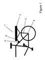
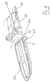
- Figure 1 demonstrates a carrier according to the present invention attached to the frame of a bicycle.
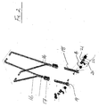
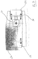
- Figure 2 details an expanded view of the mounting members and rear axle connector.
- Figure 3 shows the front connector in expanded form.
- Figure 4 is an exploded diagram of the carrier, showing the carrier top.
- Figure 5 shows a carrier top with an integrated wire frame.
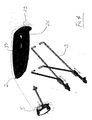
- Figure 6 details the carrier top with seat base adapter.
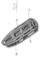
- Figure 7 illustrates the seat base with wedge securing pieces and a hand operated cam wheel.
- Figure 8 is a cross section through the seat base engaged with the carrier top.
- Figure 9 shows the seat base and cradle with suspension, in exploded form.
- With reference to figure 1, a carrier (1) for a bicycle according to the present invention is shown attached over the rear wheel of a bicycle. The bicycle carrier (1) comprises a carrier top (2), which can either be used as it appears in the figure as a simple bicycle carrier (1), or it can be integrated with further components which are described in detail below. Attached to this carrier top (2) in a removable manner, are one or more supporting members (3) which extend from the carrier top (2) to mounting points (4) provided on the cycle frame for supporting the carrier (1) and load. The mounting points (4) are positioned in the close vicinity of the rear axle of the bicycle, as is shown in figure 1, and are designed to be fixed to the bicycle and left in place when the carrier (1) is not being used.
- It is envisioned, that the mounting points (4) will be fixed to the frame of the bicycle using either a screw or a nut and bolt arrangement, utilising an eyelet in the bicycle frame provided for the connection of cycle carriers. Should no such connection point exist, it is a straightforward matter to drill a hole of suitable size in the frame of the bicycle, at the point which extends around the rear wheel axle to fix the wheel to the frame. It is further possible, that the mounting point (4) be integrated with the axle of the rear wheel, and be positioned around the axle between the hub of the rear wheel and the inner side of the frame.
- In order for the cycle carrier (1) to be readily attached and removed from the cycle frame, the rear mounting points (4) provide a pin for interacting with the lower end of the supporting members (3), this is best seen in figure 2. The lower end of the supporting members (3), are provided with slots (19) which are designed to accommodate the pin of the mounting points (4). When fitting the carrier (1) to the bicycle, all that is required to ensure a secure load bearing connection, is to slide the slots (19) at the end of the supporting members (3) over the pins provided by the mounting points (4). As a modification to the mounting points (4), and so as to stop sideways movement of the supporting members (3) from disengagement with the pin, the mounting points (4) can be provided by mushroom connectors. These mushroom connectors are cylindrical in shape, and are provided with a bore which extends through the central axis of the connector to be used for fixing to the bicycle. The outer surface of the connector varies in diameter along its length in a step wise manner, so that at either end of the connector the diameter is greater than in the middle. This, therefore, provides a connector which has an "H" profile, wherein the slots (19) at the end of the supporting members (3) are designed to fit within the region of reduced diameter and thereby be prevented from slipping off the mounting point (4).
- To further fix the carrier (1) to the frame of the cycle, there is provided a front connector (5) which is positioned at a point forward of the mounting points (4). This front fixing point is designed and provided to stop rotation of the carrier (1) around the rear axle mounting points (4). The front connector (5) can be most clearly seen in figure 3, which shows an expanded view of the key components of the connector (5). As with the rear axle mounting points (4), this front connector (5) is intended to be semi-permanently fitted to the frame of the cycle, and left in place when the rest of the carrier (1) has been removed. Shown in figure 3, are two brackets (6) which are provided to fix the front connector (5) to carrier fixing points provided on the rear wheel forks of most cycles. Shown in the diagram are L-shaped brackets, although it is to be understood that the brackets (6) are not limited to these, and can be changed for simple plate brackets depending upon the fixing points on the cycle. The fixing brackets (6) are adjustably attached to the front connector (5) to accommodate a variety of widths in the bicycle side fixing points. As can be seen in figure 3, two slots (7) are provided passing through the body of the front connector (5) through which bolts (8) are passed for engaging with the fixing brackets (6) at the desired spacing.
- As shown in figure 1, the carrier (1) is attached to the front connector (5) by means of an adjustable securing rod (9). This rod (9) is fixable at one end to the carrier top (2) in a removable and adjustable manner, so that the carrier can be used with a variety of bicycle designs and shapes. At the carrier top (2) the securing rod (9) either engages with one of a plurality of fixing points which allow it to be rotationally secured, or with a track which runs along the length of the carrier top (2) to which the rod (9) is clamped, again allowing for rotation of the rod (9) to accommodate different cycle frame designs. The securing rod (9) is engaged with the front connector (5) via a bore (10), which passes through the body of the connector (5). This bore (10) passes through the connector (5) in a direction which is substantially perpendicular to that between the carrier (1) and the front connector (5). In this manner, it is only required for the rod (9) to be bent into a configuration that will allow one end to slide into the bore (10) with the other being attached to the carrier top (2), so as to fully secure the carrier (1) and stop it from rotating around the rear axle mounting points (4).
- For increased security in the above described fixing between the rod (9) and the front connector (5), a locking mechanism is provided. As is shown in figure 3, this locking mechanism is in the form of a button (11), which is biased by means of a spring (12). The actual locking mechanism is formed by a plate (13) which has 2 right angle bends in it, wherein the two opposing faces of this plate (13) are positioned within the connector and cross the path of the bore (10). Two holes are provided in these opposing faces in appropriate positions, so that when the plate (13) is fully engaged within the front connector (5) these holes align with the bore (10). Under the influence of the spring (12), however, the plate (13) is pushed out of the connector (5) body, and the holes on the plate become misaligned with the bore (10). As is shown in the figures, if the end of the rod (9) engaging with the front connector (5) is provided with a groove (14) toward its end, the edge of one of the holes in the biased plate will slot into this groove (14), when the rod is fully within the connector. Indeed, as the bore (10) is accessible from both sides, it is necessary to provide the locking mechanism working with both orientations of the rod (9); this is achieved by use of the plate (13) crossing the bore (10) in two positions. This provides an additional security feature in that, whilst the rod (9) is being inserted into the bore (10), the groove (14) will engage with the first side of the plate (13) and will therefore be stopped from slipping out again. Pressing of the button (11), will then allow the groove (14) to be disengaged from the holes in the plate (13) and the end of the rod (9) can be fully inserted within the bore (10). Clearly, the above double locking mechanism works in reverse: should the rod (9) become dislodged from the hole in the first side of the plate (13) and slide outward of the front connector (5), the groove (14) will be engaged with the second side of the plate, and will therefore be retained. In order to facilitate sliding the rod (9) into the bore (10) for engagement, it is possible to chamfer the relevant end, or even provide it with a point.
- As can be seen in figure 3, the front connector further includes a safety strap (15). This strap (15) is attached to the front connector (5) via the bolts (8), and is designed to pass around the back of the frame of the bicycle to which the connector (5) is attached. In this way, should the fixing mechanism holding the front connector (5) to the frame fail, the front connector (5) will still remain fixed to the frame and will not allow the carrier (1) to rotate or become unattached. Whilst the diagram has shown this safety strap (15) connected through the bolts (8) used for adjusting the width of the fixing brackets (6), any other method of securing the strap (15) to the front connector (5) around the frame is believed as being considered obvious by the skilled man and falling within the scope of the design. For instance, the strap (15) could be attached to the connector (5), and when the connector (5) is fixed to the frame the strap (15) is passed around the frame and the two ends are connected together, by means of a buckle or a clip, for instance.
- As can be seen from figure 3, a modification to the design of the fixing rod (9), includes it having multiple bends. This design is particularly useful, as it further allows for the carrier (1) to be fastened to a wider range of cycles. The rod (9) in fashioned is such a manner, that the direction of the central axis at each end of the rod (9) lies perpendicular to each other, which therefore allows one end to fasten to the carrier top (2) with the other being engaged in the front connector (5). Secondly, these two axes do not lie in the same plane as each other and are separated by a chosen distance. In this manner, when the rod (9) is inserted into the bore (10) of the front connector (5), by choosing which side to insert from, the height of the rod (9) can be adjusted. This adjustment is designed to allow for different frame designs, wherein the relationship between the front connector (5) frame attachment points and the height of the carrier top (2) above the rear wheel differs.
- In order to allow the carrier (1) to be fixed to a variety of cycles, the length of the supporting members (3) attached to the carrier top (2) can be varied. This is most simply achieved by the system as shown in figure 2. Herein, two sets of rods (16) are shown which extend from the carrier top (2) to a height adjusting block (17), to be held within. Whilst the diagram shows four rods grouped in pairs, it is to be understood that this is by way of example only, and that more or fewer can be used if so required. Furthermore, whilst it is envisioned that these rods be made from aluminium for both lightness and strength, it is clearly possible to fabricate them out of a different metal or indeed a rigid plastic. The rods (16) are designed to interact with the carrier top (2) and fasten thereto in a removable manner, and are shown in the figures attached to the underside of the top (2). Other designs, however, which fulfil the same function are clearly possible, and that shown in the figure is intended as one possible solution.
- The height adjusting block (17), to which the lower end of the support rods (16) are attached, further interacts with a height plate (18), which has at its lower end the slot (19) for sliding over the rear mounting point (4). The height plate (18) comprises a rigid plate of metal which has a series of holes spaced out along its length, such that when the slot (19) is in position around the rear mounting point (4) the holes extend in an upward direction. The height adjusting block (17) is possessed of a slot which is sized to accept the height plate (18); further, the block (17) is provided with a fixing pin which engages with the desired hole, and thus positions the adjusting block (17) at the desired height.
- Whilst the engagement of the slot (19) in the height plate (18) over the rear mounting point (4) is a straightforward method of attaching the rear of the carrier (1) to the frame of the bike, it requires a locking mechanism to stop the motion of the bike from bouncing the carrier (1) out of the mount (4). This is most readily achieved by providing a clip (20) at the end of the height plate (18), for sliding underneath and around the rear mounting pin (4), and in this way securing the plate (18). Such a clip (20) would be affixed in a rotatable manner to the end of the height plate (18), on one of the arms either side of the slot (19). Once the height plate (18) is engaged with the rear mounting point (4), the clip (20) can be rotated from its open position allowing access to the slot (19) to the closed position, wherein it passes under the rear mount (4) and stops the height plate (18) from disengaging as a result of the motion of the cycle. As an additional feature, it is possible to bias this clip (20) by means of a spring (21), thereby ensuring that the clip is always engaged with the rear mounting point (4), and as such increasing the security of the locking mechanism. Moreover, to maintain this clip (20) assembly in good working order, and avoid its degradation from either physical knocks or from dirt and/or oil, a protective cap (22) can be provided to cover the clip (20) and spring (21).
- The above disclosed arrangement for attaching the carrier (1) to a cycle, means that one carrier (1) can be used with a range of cycles. This is particularly desirable when multiple users, say within a family, wish to use just one carrier (1). Provision of multiple front connectors (5) and rear axle mounts (4) attached to several cycles, in addition to the above disclosed adjustable support members (3) and securing rod (9), leads to a carrier (1) which can readily be moved from one cycle to another.
- Figure 4 is an exploded diagram detailing how the carrier top (2), the front connector (5) and the supporting members (3) are disposed to make the basis of the carrier (1). As shown in this figure, the preferred number of supporting members (3), each of which comprises a pair of rods (16), is two, that is: one either side of the rear wheel. Further provided on the carrier top (2) is one half of a dovetail joint (23), for the secure connection of further carrier elements as detailed below. Shown in figure 4, is a carrier top (2) which is fully formed as a single unit, preferably out of a rigid plastic material, in which the half dovetail joint (23) is positioned toward the outer edge of the top (2). Another possible method of providing one half of a joint for attachment of further carrier elements, is shown in figure 5, wherein a rigid wire (24) is situated above the carrier top (2) upper surface in a loop. This rigid wire loop (24) provides a fixing point which can be treated as one half of a dovetail joint, as in the case where the carrier top (2) is formulated from a single unit. The loop can also be used for attaching items to the carrier in the same way as the slots (25), which can be seen in figures 4 and 5, passing through the carrier top (2), securing the items by means of straps, rope, string or the like.
- The half dovetail joint in the carrier top (23), is specifically intended for interfacing the carrier top (2) with further elements of the carrier (1); figure 6 shows one such element in the form of a seat base (26). This seat base (26) is designed such that its underside has a half dovetail joint (27) which is the matching half of the carrier top dovetail joint (23). Attachment of the seat base (26) to the carrier (1), is by the simple sliding of the seat base (26) over the carrier top (2) such that the two halves of the joint engage. In the case that the carrier top (2) has a wire loop for the attachment of the seat base (26), the seat base (26) slides over this for attachment. Whilst the figures show the carrier top (2) being possessed of the tenon to the joint, in the case of the wire loop carrier (24) the seat base (26) has the mortise which slides over and around the loop, it is equally possible for these to be reversed. In this situation, the carrier top (2) has a dovetail shaped recess into which a tenon on the seat base (26) can slide; the wire loop carrier (24) is adapted so that the seat base tenon slides between the two sides of the loop to engage therewith.
- The dovetail joint between the carrier top (2, 24) and seat base (26) clearly stops the two elements from disengaging vertically, but there remains the possibility of the base (26) sliding off from the carrier (2). In order to obviate this problem, the seat base (26) can be fitted with at least one hand operable locking mechanism. Two solutions for this locking system are presented: a mechanism for causing the two halves of the dovetail joint to be gripped together so as to remove any play from the joint and stop the sliding disengagement; and a rotatable safety lock (28) which is connected to the seat base (26), and has projections that extend below the bottom of the seat base (26) to interact with the carrier top (2, 24). It is conceived that one or both of the above locking systems be fitted to the carrier (1) of the present invention, although with a well fitting dovetail joint (23, 27) it is possible that neither would be necessary.
- Several solutions exist for removing the play from the dovetail joint, either the two halves are forced apart vertically, so that the tenon is forced into tight engagement with the mortise, or the seat base (26) is formed such that it can be deformed slightly and act so as to grip the carrier top (2, 24), or the rods of the loop carrier (24) can be moved to grip the seat base (26). The method of forcing the two halves of the joint apart, is best achieved by providing 2 wedges (29), see figure 7, which fit within the dovetail joint in between the seat base (26) and the carrier top (2). These wedges (29) are biased, with the aid of springs (30), pulling them together toward the centre of the carrier top (26). The wedges (29) are oriented so that the narrow portions face each other, and when they are pulled together by the biasing springs (30), thicker and thicker portions are introduced into the gap between the two halves of the joint and thus it is pushed apart and more securely held. In order to remove the wedges (29) from the joint, and allow the seat base (26) to be removed from the carrier top (2), a cam wheel (31) is mounted within the seat base (26) such when it is rotated, it acts upon linear extensions of the wedges (29) and pushes them apart. This cam wheel is provided with a grip and is intended to be hand operated. Clearly, the cam wheel (31) must be in the position that forces the two wedges (29) apart for mounting or removal of the seat base (26) onto the carrier top (2). As the wedges act upon the carrier top (2), this method is particularly suited to the solid carrier top (2), rather than the wire loop top (24).
- Secure fixing of the seat base (26) by deformation, requires that this base (26) is formed from a piece of plastic in the shape of a "U"; that is, it has two extending arms which are separated by a small gap. When the seat base (26) is positioned in the carrier top dovetail joint (23), these two arms are either squeezed together or pushed apart by hand operated means and therefore secure the dovetail joint. Shown in figure 6 is a locking lever (32), which has an extension passing through one of the seat base (26) arms to be secured in the other. This design is appropriate for when the carrier top (2) has the tenon of the dovetail joint, whether provided in the moulded plastic carrier top (2) or the carrier top possessing the rod loop (24), and the seat base (26) the mortise. As the lever (32) has an eccentric mounting point at one end of the extension, when it is rotated it acts upon the side of the seat base (26) and pushes the first arm toward the second, and in so doing grips the carrier top tenon (23). Whilst in the figure a lever (32) is shown, it is clear that other systems exist, such as a hand operated screw thread, which upon rotation pushes the two arms of the seat base (26) together. Additionally, in the system which employs a wire loop carrier top (24), it is possible to bias the rods outward so as to engage more tightly with the mortise of the seat base (26) and so secure the joint. This could be achieved by means of a hand operated screw thread, which upon rotation acts to force the rods apart.
- When the converse system to that above is utilised, that is where the seat base (26) presents the tenon of the dovetail joint, to either fit within a moulded mortise in the carrier top (2), or within the rods of the carrier (24), a different locking mechanism is required. In this case, it is possible to still utilise the seat base (26) formed as a "U", as detailed above, however, instead of using a system to push the two arms together, the biasing is required to pull the two arms apart and so engage the two halves of the dovetail joint in tight connection. The simplest method of performing this task, is by providing a screw thread which passes through one of the arms and impinges upon the other. Rotation of the screw in the appropriate direction, will drive the end of the screw into the second arm of the seat base (26) and force the two apart and into tight engagement within the joint. It is also possible, to have a screw thread engaged with both arms, wherein each half has a thread of opposite thread direction, such that rotation will cause both arms to be forced apart. An additional method of gripping the tenon on the seat base (26) is possible, if the carrier top (24) has the rigid wire loop configuration. Here, when the tenon is engaged between the rods, application of a force to move the rods together will grip the seat base (26) firmly to the carrier top (24). This gripping force could most readily be achieved by means of screw thread operated clamps attached to each of the rods.
- Figure 6 shows the relative positioning of the safety lock (28), if present, within the seat base (26) for further ensuring that it does not accidentally disengage from the carrier top (2, 24). Figure 8, shows a cross section through the engaged carrier top (2) and seat base (26) taken along the line A-A in figure 6. Clearly visible is the projection from the safety lock (28) which extends below the bottom surface of the seat base (26) to engage with a resilient side of a recess (33) in the carrier top (2). This recess (33) can be more clearly seen in figure 6. As the seat base (26) is slid into engagement with the carrier top (2), the safety lock (28) rotates around the pivot point (34) and the projection end rises out of the dovetail joint region, until the recess (33) is reached. At this point, the projection drops down to engage the locking mechanism and prevents the seat base (26) from sliding back and disengaging from the carrier top (2). Whilst it is possible to allow this lock to work under the force of gravity alone, it is preferable to spring bias the rotation of the member to ensure that the lock (28) properly engages, and further prevent the motion of the cycle from bouncing it out of position.
- Figure 9 shows the seat base (26) of figure 6 with additional elements of the seat for integration with the carrier (1). As can be seen in the figure, the seat base (26) is possessed of a series of projections (35) extending upward at one end of the base (26).
- Preferably, these projections (35) are formed such that they are positioned at the front of the carrier (1) when it is fixed to the cycle, although this is not necessary. These projections (35) provide one half of a rotatable hinge for integration of further seat elements, such as the cradle (36) shown in figure 9. Through the projections (35) in the seat base (26) are a series of holes (37) which each align along a central axis in a direction perpendicular to the direction of motion of the cycle. As can be seen in figure 9, the underside of the cradle (36) is provided with a second set of projections (38) with holes (39) through. The two sets of projections (35, 38) are so designed as to interdigitate with each other such that the sets of holes (37, 39) align and with insertion of a split pin (40) form a hinge. This pin (40) can be formed in many ways, as two halves of a single pin (40) which after insertion into the holes (37, 39) are joined together; or as two shorter pins (40) which fit through half of the interdigitated projections (35, 38) only, and which form into the hinge in this manner. If the two separate pin (40) option is utilised, the inserted end is provided with a deformable section which after insertion through the holes (37, 39), stops the accidental removal of the pin (40) from the hinge.
- The provision of a hinge section between the seat base (26) and the cradle (36) is so that a suspension system can be incorporated between these two elements. It is desirable, however, that the cradle (36) cannot rotate too far forward away from the seat base (26), as this could lead to a further element attached to the cradle (36) tipping too far forward, which could prove dangerous. In order to stop this from occurring, the cradle (36) has formed shoulders (41) which match the contour of the seat base projections (35). These shoulders (41) are positioned around the seat base projections (35) and will only allow the cradle (36) to rotate so far away from the seat base (26). As can be seen in figure 9, the cradle unit (40) is provided with attachment points on its upper surface which are used for attachment of further carrier elements. Such elements could be, but are not limited to, a child's seat (42) or other carrying units, such as a box.
- In order to improve the ride comfort for a child using the child's seat (42), or for reducing the number of potentially content damaging bounces the carrier unit suffers during the use of the cycle, suspension blocks (43) can be placed between the rotateably interconnected seat base (26) and cradle (36). These suspension blocks (43) are preferably made from rubber, as this is a naturally deforming substance with long durability, however, any appropriate elastomeric substance could be used. As a further option, the positioning of these blocks (43) with respect to the hinge point, can be altered so as to adjust the suspension effect. These suspension blocks (43) are either held within specific fixing points provided on the top surface of the seat base (26) and corresponding points on the lower surface of the cradle (36), or a fixing track is provided on each of these carrier elements so as to allow the positioning of the block in a range of places to give a truly variable suspension effect.
- Further shown within figure 9, is an adjustment spindle (44), which can further be used to alter the level of travel available between the cradle (36) and the seat base (26). The spindle (44) shown, has a screw thread which is in threaded engagement with a nut (45); this nut (45) being held within the cradle (36). At one end of the spindle (44) is a hand operated grip for rotation of the thread to adjust the position of the spindle (44) with respect to the nut (45), with the other end of the spindle (44) resting on the seat base (26). Clearly, with this arrangement, rotation of the spindle (44) will drive the one end into the seat base (26) and thereby adjust the amount of rotation which is possible between the cradle (36) and the seat base (26). Whilst a nut (45) is shown in the figure, it is also possible that the cradle (36) be possessed of a threaded section for attachment of the spindle (44), thereby removing the need for a separate nut (45).
- A further requirement of the spindle (44), is to integrate with the further elements which are attached to the cradle (36), be these the child's seat (42), storage boxes or the like. The hand operated end of the spindle (44) is required to be accessible when the further elements are attached, whilst additionally not getting in the way of the functioning of the elements. A further function that the spindle can perform, is to provide another fixing point between the seat (42) or storage element, and the cradle (36). In order to achieve this, the spindle is housed within the seat (42) or storage element, such that it can be rotated to allow adjustment of the suspension, whilst still connecting the element to the cradle (36).
- While various features and embodiments of the invention are described above, they can readily be combined with each other resulting in further embodiments of the invention.
Claims (52)
- A carrier (1) for a bicycle comprising:a carrier top (2);rear axle mounts (4);wherein the carrier top (2) is connectable to one or more supporting members (3) which are attachable to the carrier top (2) and extend from the carrier top (2) toward the rear axle mounts (4), these axle mounts (4) being fixed to the frame of the bicycle and providing a pin which engages with the supporting members (3) via a slot (19) in the end of each of the members (3) the slot (19) being shaped for sliding over the pin and fixing the carrier assembly to the bicycle;a front connector (5) is provided, which is fixed to the frame of the bicycle in a position forward of the rear axle, for attaching the front of the carrier top (2) to the bicycle to give support and to stop the carrier (1) from rotating about the rear axle mount (4); wherein,the carrier top (2) and front connector (5) are interconnected by means of an adjustable securing rod (9) which is secured in a removable manner to the carrier top (2), the rod (9) extending from the carrier top (2) such that its second end can be positioned and held within a channel (10) provided in the front connector (5) to secure the carrier (1) whilst further meaning that it can be fitted to a variety of bicycle designs, the channel (10) lying in a direction which is perpendicular to the direction of motion of the bicycle.
- The carrier (1) of claim 1, wherein the front connector (5) further comprises:brackets (6) for attaching the connector (5) to the carrier connection points on the frame of the bicycle via screws or bolts, wherein the distance between the two brackets (6) can be adjusted to accommodate a variety of widths of connection points.
- The carrier (1) of claim 1, wherein the front connector (5) further comprises:a bracket for extending around one or more of the tubes of a bicycle in order to grip the tube between the bracket and the main body of the front connector (5) to attach it to the frame;the fixing bracket being attached to the connector (5) via a hinge at one side, and being connectable to the connector (5) on its other side via means of a hand operable mechanism.
- The carrier (1) of claims 1 to 3, wherein the channel (10) of the front connector (5) comprises:a bore (10) extending through the full length of the body of the connector (5) with a diameter that is large enough to accommodate the securing rod (9), whilst further allowing the end of the rod (9) to be inserted into either end of the bore (10).
- The carrier (1) of claims 1 to 4, wherein the front connector (5) further comprises:a safety lock disposed along the length of the bore (10), such that when the securing rod (9) is fully inserted within the connector (5) it is locked in place and cannot slide out.
- The carrier (1) of claim 5, wherein the safety lock comprises:a plate (13) with two right-angle bends in it to form a "U" shape, with holes of the same size as the bore (10) drilled through the opposing portions of the plate (13),slots (7) in the connector (5) which are shaped and positioned to accept the opposing portions of the locking plate (13), and which extend perpendicular to the axis of the bore (10) and cross its path, wherein,the holes in the locking plate (13) are positioned such that when the opposed portions of the plate (13) are inserted into the slots (7), the holes align with the bore (10),the plate (13) further being biased by means of a spring (12) to push the holes out of alignment with the bore (10),the end of the securing rod (9) for inserting into the connector (5), being provided with a groove (14) at the appropriate position so that it can interact with the biased plate (13) such that the inside edge of the hole will be pushed into the groove (14) and the rod (9) will be secured in place.
- The carrier (1) of claims 1 to 6, wherein the front connector (5) is further provided with a safety strap (15), this safety strap (15) being secured to the body of the connector (5) in a removable fashion, and being positioned such that it extends around the back of the connector (5) for encircling the section of frame to which the connector (5) is fixed, thereby ensuring that if the primary fastening mechanism fails, the connector (5) remains connected to the bicycle and the carrier (1) remains secure.
- The carrier (1) of claim 1 to 7, wherein the securing rod (9) is secured to the carrier top (2) either at one of a plurality of integrated fixing points, or to a fixing track which is provided with a hand operable clamping mechanism.
- The carrier (1) of claims 1 to 8, wherein one end of the securing rod (9) is provided with a fastening mechanism for removable connection to one of the integrated fixing points on the carrier top (2), wherein the fastening mechanism provides a means for allowing the rod (9) to rotate around the fixing point in a vertical direction, as defined when the carrier top (2) is attached to the bicycle, thereby allowing the carrier (1) to be secured to a variety of bicycle designs.
- The carrier (1) of claims 1 to 9, wherein the securing rod (9) is fashioned such that the central axis of the rod (9) at each of the ends lie at 90° with respect to each other, wherein the two axes do not cross each other and are separated by a preset distance.
- The carrier (1) of claims 1 to 10, wherein the securing rod (9) has a chamfered end to ease insertion into the front connector (5) and integration through the holes in the locking plate (13).
- The carrier (1) of claims 1 to 11, wherein the rear axle mount (4) comprises a mushroom connector fastened to the frame of the bicycle, this mushroom connector being cylindrical in shape and possessing an outer diameter which varies in a stepwise fashion along its length, from a larger diameter to a smaller and then back to the first diameter to resemble an "H", thereby providing a fixing means for the support members (3) of the carrier (1).
- The carrier (1) of claim 12, wherein the mushroom connector comprises a longitudinal bore running the length of the connector and along the central axis, the bore being used to secure the connector to the frame by means of a screw or bolt.
- The carrier (1) of claim 12, wherein the mushroom connector comprises a longitudinal bore running the length of the connector and along the central axis, the bore being wide enough to be positioned on the real wheel axle, between the frame of the bicycle and the hub of the rear wheel so as to secure the connector to the bicycle.
- The carrier (1) of claims 12 to 14, wherein the width of the reduced diameter region of the mushroom connector is wider than the width of the support members (3) in the slot (19) region.
- The carrier (1) of claims 1 to 15, wherein the supporting members (3) include a height plate (18) and an associated adjustment block (17) for adjusting the height of the carrier top (2) above the rear axle mount (4).
- The carrier (1) of claim 16, wherein the height plate (18) is formed from a rigid strip, at one end of which is the slot (19) for integrating with the pin of the rear axle mount (4) and along its length the plate is provided with a series of holes for adjusting the fastening point between the plate (18) and the height adjustment block (17).
- The carrier (1) of claims 16 or 17, wherein the height adjustment block (17) comprises a slot for accepting the height plate (18) and for facilitating the slide-able positioning of the block (17) at the desired point on the height plate (18), the height adjustment block (17) being kept in place by means of a pin which passes through the chosen hole of the height plate (18).
- The carrier (1) of claims 16 to 18, wherein the height adjustment block (17) is attached to one or more support rods which extend from the carrier top (2).
- The carrier (1) of claim 19, wherein the number of support rods per supporting member (3) is two.
- The carrier (1) of claims 16 to 20, wherein the height plate (18) further includes a fastening clip (20) attached in a rotatable manner to the end of the plate (18) with the slot (19), the clip (20) being positioned and shaped such that when the slot (19) in the height plate (18) is engaged with the pin, the clip (20) passes around the underside of the pin to restrain the height plate (18) and prevent accidental disengagement.
- The carrier (1) of claim 21, wherein the fastening clip (20) is spring biased into the locking position.
- The carrier (1) of claims 21 and 22, wherein the fastening clip (20) is provided with a protective cap (22) to prevent damage to the clip (20) and further to keep the mechanism and spring (21) clean.
- The carrier (1) of claims 1 to 23, wherein the carrier top (2) comprises a solid base, the underside of which is provided with means for the removable attachment of both the support members (3) and the adjustment rod (9).
- The carrier (1) of claims 1 to 24, wherein the topside of the carrier top (2) is fashioned to present either the tenon or mortise of a dovetail joint (23) for the slide-able engagement of a seat base (26) which is provided with an appropriately sized counterpart tenon or mortise (27).
- The carrier (1) of claim 25, wherein a locking mechanism is provided between the carrier top (2) and the seat base (26) to remove any play which might exist in the dovetail joint (23, 27) as a result of manufacturing tolerances.
- The carrier (1) of claim 26, wherein the locking mechanism takes the form of a pair of wedge shaped blocks (29) which are integrated with the seat base (26) in the region of the dovetail joint (23, 27), the wedge shaped blocks (29) being positioned at either end of the dovetail joint track and biased toward the centre of the seat base (26) with the narrower sections of the wedges (29) oriented in the direction of this bias; the wedge shaped blocks (29) further positioned such that the sloped face interacts with the seat base (26) body when they are biased inward, and that the wedges (29) are forced within the dovetail joint (23, 27) region to provide a means of separating the seat base (26) from the carrier top (2), thereby forcing the two parts of the dovetail joint (23, 27) together and removing any play between the two sections.
- The carrier (1) of claim 27, wherein a hand operable rotatable cam wheel (31) is provided in the seat base (26) which interacts with the wedges (29), and provides a means for moving them in the direction opposing the bias so as to remove the wedges (29) from the joint region and allow the slide-able engagement or disengagement of the seat base (26) and carrier top (2).
- The carrier (1) of claims 1 to 24, wherein the carrier top (2) comprises a series of rods, wherein two of the rods making up the carrier top (2) are positioned parallel with each other, such that a seat base (26) provided with either the mortise or tenon of a dovetail joint (27) can be slide-ably attached either around or between the parallel rods respectively, to create a dovetail joint.
- The carrier (1) of claims 25 or 29, wherein the seat base (26) is fashioned in the shape of a "U" with the two arms running parallel with dovetail track in the carrier top (2), a locking mechanism being provided which by means of a hand operable apparatus moves the two arms of the seat base (26) so as to more tightly engage the two parts of the dovetail joint (23, 27) and remove any play from the joint.
- The carrier (1) of claim 30, wherein the carrier top (2) is provided with the tenon of the dovetail joint and the seat base (26) the mortise, and the locking mechanism acts to force the two arms together so as to more tightly grip the tenon on the carrier top (2).
- The carrier (1) of claim 30, wherein the carrier top (2) is provided with the mortise of the dovetail joint and the seat base (26) the tenon, and the locking mechanism acts to force the two arms apart so that each half of the tenon of the seat base (26) is more tightly engaged with the mortise of the carrier top (2).
- The carrier (1) of claims 31 and 32, wherein the locking mechanism is provided by a screw thread and screw through the seat base (26) which, by means of a hand operable rotatable handle, moves the arms of the seat base (26).
- The carrier (1) of claim 31, wherein the locking mechanism is provided by a rotatable lever (32) which has an eccentric axle point of its rotating member, this lever (32) is mounted on a connector which passes through one arm of the seat base (26) and is fastened to the other; wherein
the locking mechanism is so designed that, upon rotation of the lever (32) and by virtue of the eccentric mounting, one arm is pulled toward the other whilst the other is pushed in the opposite direction so as to bring the two arms together to increase the grip of the seat base mortise on the tenon of the carrier top (2). - The carrier (1) of claim 29, wherein the seat base (26) is provided with the mortise of a dovetail joint and means are provided for pushing the parallel rods apart so as to more tightly engage with the seat base (26) and secure it in position.
- The carrier (1) of claim 29, wherein the seat base (26) is provided with the tenon of a dovetail joint and means are provided for forcing the parallel rods together to more tightly grip the tenon on the seat base (26), securing it in position.
- The carrier (1) of claims 25 to 36, wherein the seat base (26) is provided with a safety lock (28) which is mounted to the base (26) in a rotatable manner, the safety lock (28) being provided with extensions which pass through the seat base (26) to engage with resilient features on the carrier top (26) underneath, in such a manner that the seat base (26) is prevented from sliding off the carrier top (2) without first rotating the safety lock (28) and disengaging the extensions from the resilient features in the carrier top (2).
- The carrier (1) of claim 37, wherein the safety lock (28) engages with the carrier top (2) by means of gravity pulling it into position.
- The carrier (1) of claim 37, wherein the safety lock (28) is biased into the engagement position with the carrier top (2), by means of a spring.
- The carrier (1) of claims 25 to 39, wherein a plurality of protrusions (35) are provided extending upward from the top side of the seat base (26), these protrusions (35) being shaped and arranged at one end of the seat base (26) so as to form one half of a hinge for attachment of a cradle (36).
- The carrier (1) of claim 40, wherein each of the plurality of protrusions (35) has a hole (37) passing through it of the same size and sharing the same central axis, this hole (37) being provided for accepting a separable axle pin (40) for the removable attachment of the cradle (36).
- The carrier (1) of claims 40 and 41, wherein the underside of the cradle (36) is provided with a series of protrusions (38) which integrate and interdigitate with those provided on the top side of the seat base (26), the cradle protrusions (38) being provided with holes (39) through them of the same size and sharing the same axis such that the two sets of protrusions (35, 38) can be interlocked and the separable axle pin (40) passed through each of the holes (37, 39) to secure the cradle (36) to the seat base (26) via a rotatable hinge engagement.
- The carrier (1) of claims 40 to 42, wherein the cradle (37) is provided with a shoulder (41) which extends between the protrusions (38) and follows the same contour as the to limit the amount of opening of the hinge between the seat base (26) and the cradle (36), thereby stopping the cradle (36) from tipping too far forward.
- The carrier (1) of claims 40 to 43, wherein the top surface of the cradle (36) is provided with fittings for the attachment of further carrier elements.
- The carrier (1) of claim 44, wherein the further element is a child's seat (42).
- The carrier (1) of claim 44, wherein the further element is a carrying unit, such as a box.
- The carrier (1) of claims 25 to 46, wherein suspension blocks (43) are provided between the cradle (36) and the seat base (26), so as to dampen the motion of the cradle (36) and any further attached elements, whilst the bicycle is in motion.
- The carrier (1) of claim 47, wherein the top surface of the seat base (26) and the lower surface of the cradle (36) are further provided with features and fixing points for incorporating the suspension blocks (43).
- The carrier (1) of claim 48, wherein the features and fixing points allow for the suspension blocks (43) to be positioned in a range of positions with respect to the hinge, so that the effect and extent of the suspension can be adjusted.
- The carrier (1) of claims 47 to 49, wherein there is further provided an adjustment spindle (44) which has a hand operable grip on one end with the other end resting against the seat base (26), in such a manner that the spindle (44) passes through the cradle (36), an associated screw thread is provided in the cradle (36) with which the spindle (44) is threadably engaged, the spindle (44) being oriented such that upon rotation the spindle (44) provides a means for fixing the relative positions of the cradle (36) and seat base (26) and removing the suspension effects of the hinge and blocks, or for altering the amount of travel possible between the cradle (36) and the seat base (26) so as to adjust the suspension effect.
- The carrier (1) of claim 50, wherein the screw thread in the cradle (36) is provided by a removable nut (45) housed within the cradle (36).
- The carrier of claims 50 and 51, wherein the spindle (44) is further adapted such that it will pass through the body of a child's seat (42) if integrated with the cradle (36) in such a manner that it does not interfere with the seating position of the child, whilst providing a further method of securing the seat (42) to the cradle (36).
Priority Applications (13)
| Application Number | Priority Date | Filing Date | Title |
|---|---|---|---|
| EP05006609A EP1705109B1 (en) | 2005-03-24 | 2005-03-24 | Carrier rack for a bicycle |
| DE602005018160T DE602005018160D1 (en) | 2005-03-24 | 2005-03-24 | Luggage rack for bicycles |
| AT05006609T ATE451293T1 (en) | 2005-03-24 | 2005-03-24 | LUGGAGE RACK FOR BICYCLES |
| PL05006609T PL1705109T3 (en) | 2005-03-24 | 2005-03-24 | Carrier rack for a bicycle |
| DK05006609.1T DK1705109T3 (en) | 2005-03-24 | 2005-03-24 | Luggage carrier for a bicycle |
| AT08157573T ATE509822T1 (en) | 2005-03-24 | 2006-03-23 | ATTACHMENT FOR A LUGGAGE RACK |
| PCT/IB2006/000666 WO2006100579A1 (en) | 2005-03-24 | 2006-03-23 | Carrier rack for a bicycle |
| AT08157590T ATE513731T1 (en) | 2005-03-24 | 2006-03-23 | BUILDING PLATE |
| EP06727355A EP1877297A1 (en) | 2005-03-24 | 2006-03-23 | Carrier rack for a bicycle |
| US11/576,680 US20090159626A1 (en) | 2005-03-24 | 2006-03-23 | Carrier rack for a bicycle |
| EP08157590A EP1958857B1 (en) | 2005-03-24 | 2006-03-23 | Mounting base |
| EP08157573A EP1958856B1 (en) | 2005-03-24 | 2006-03-23 | Carrier top |
| PT08157573T PT1958856E (en) | 2005-03-24 | 2006-03-23 | Carrier top |
Applications Claiming Priority (1)
| Application Number | Priority Date | Filing Date | Title |
|---|---|---|---|
| EP05006609A EP1705109B1 (en) | 2005-03-24 | 2005-03-24 | Carrier rack for a bicycle |
Publications (2)
| Publication Number | Publication Date |
|---|---|
| EP1705109A1 true EP1705109A1 (en) | 2006-09-27 |
| EP1705109B1 EP1705109B1 (en) | 2009-12-09 |
Family
ID=35455887
Family Applications (4)
| Application Number | Title | Priority Date | Filing Date |
|---|---|---|---|
| EP05006609A Not-in-force EP1705109B1 (en) | 2005-03-24 | 2005-03-24 | Carrier rack for a bicycle |
| EP08157590A Not-in-force EP1958857B1 (en) | 2005-03-24 | 2006-03-23 | Mounting base |
| EP06727355A Withdrawn EP1877297A1 (en) | 2005-03-24 | 2006-03-23 | Carrier rack for a bicycle |
| EP08157573A Not-in-force EP1958856B1 (en) | 2005-03-24 | 2006-03-23 | Carrier top |
Family Applications After (3)
| Application Number | Title | Priority Date | Filing Date |
|---|---|---|---|
| EP08157590A Not-in-force EP1958857B1 (en) | 2005-03-24 | 2006-03-23 | Mounting base |
| EP06727355A Withdrawn EP1877297A1 (en) | 2005-03-24 | 2006-03-23 | Carrier rack for a bicycle |
| EP08157573A Not-in-force EP1958856B1 (en) | 2005-03-24 | 2006-03-23 | Carrier top |
Country Status (8)
| Country | Link |
|---|---|
| US (1) | US20090159626A1 (en) |
| EP (4) | EP1705109B1 (en) |
| AT (3) | ATE451293T1 (en) |
| DE (1) | DE602005018160D1 (en) |
| DK (1) | DK1705109T3 (en) |
| PL (1) | PL1705109T3 (en) |
| PT (1) | PT1958856E (en) |
| WO (1) | WO2006100579A1 (en) |
Cited By (3)
| Publication number | Priority date | Publication date | Assignee | Title |
|---|---|---|---|---|
| EP2275332A1 (en) * | 2009-07-16 | 2011-01-19 | Hamax As | Bag adaptor |
| US10513299B2 (en) | 2017-10-08 | 2019-12-24 | Henry Gordon MacMorran | Adjustable bicycle rack |
| EP3854666A1 (en) * | 2020-01-27 | 2021-07-28 | Curana Invest bvba | Assembly of two mutually connectable bicycle components |
Families Citing this family (8)
| Publication number | Priority date | Publication date | Assignee | Title |
|---|---|---|---|---|
| US9187142B2 (en) | 2009-08-24 | 2015-11-17 | Arkel Inc. | Cantilever bike rack |
| US9079626B2 (en) | 2011-05-25 | 2015-07-14 | Robert David Zuraski | Portable lock mounting assemblies |
| CN103958270B (en) | 2011-05-25 | 2016-05-04 | 施拉奇锁有限责任公司 | For the lock installation component of conveying arrangement |
| US9302725B2 (en) * | 2013-03-14 | 2016-04-05 | Bell Sports, Inc. | Locking rack system for bicycles |
| US9694867B2 (en) * | 2013-03-14 | 2017-07-04 | Bell Sports, Inc. | Locking rack system for bicycles |
| US11535331B2 (en) * | 2017-08-30 | 2022-12-27 | Dongguan Hong Lin Industrial Co., Ltd | Bicycle mounting mechanism and battery box assembly |
| CN112158284B (en) * | 2020-10-19 | 2021-11-02 | 无锡如森电动车有限公司 | Bearing substrate mechanism for electric vehicle |
| TWI791398B (en) * | 2022-04-14 | 2023-02-01 | 鄭寧元大 | shelf structure |
Citations (4)
| Publication number | Priority date | Publication date | Assignee | Title |
|---|---|---|---|---|
| US4350361A (en) * | 1979-12-06 | 1982-09-21 | Chiaki Fujii | Load carrying platform for a bicycle |
| US4666071A (en) * | 1986-01-24 | 1987-05-19 | Cannondale Corporation | Bicycle rear carrier rack |
| DE4339761C1 (en) * | 1993-11-22 | 1995-04-13 | Wolfgang Weger | Luggage carrier for two-wheeled or multi-wheeled vehicles, in particular bicycles |
| US5803329A (en) | 1995-04-24 | 1998-09-08 | Gebruder Pletscher Ag | Carrier rack for a two-wheeled vehicle, in particular for a bicycle |
Family Cites Families (27)
| Publication number | Priority date | Publication date | Assignee | Title |
|---|---|---|---|---|
| US1963333A (en) * | 1932-02-13 | 1934-06-19 | Mormye Inc | Carrier |
| US4053091A (en) * | 1976-05-28 | 1977-10-11 | Sears, Roebuck And Co. | Combination rear luggage carrier and child seat for bicycle |
| US4030648A (en) * | 1976-09-20 | 1977-06-21 | The Firestone Tire & Rubber Company | Carrier support apparatus |
| US4562944A (en) * | 1979-02-01 | 1986-01-07 | Eclipse, Inc. | Adjustable connections on cycle rear carrier |
| US4353490A (en) * | 1979-10-24 | 1982-10-12 | Jackson W S | Pannier mounting system for cycles |
| US4266703A (en) * | 1980-01-28 | 1981-05-12 | Reuben Litz | Slide mount for motorcycle luggage box |
| US4440331A (en) * | 1981-12-03 | 1984-04-03 | Schimmels Kristin L | Protective child carrier assembly |
| JPS58145271U (en) * | 1982-03-26 | 1983-09-30 | 川崎重工業株式会社 | Article storage box mounting device for motorcycles |
| US5299818A (en) * | 1989-09-29 | 1994-04-05 | Bell Sports, Inc. | Child's bicycle seat and rack assembly |
| US5244132A (en) * | 1991-06-06 | 1993-09-14 | Lisa Christen | Garment bag and support rack therefor for use with bicycle |
| US5411190A (en) * | 1991-09-06 | 1995-05-02 | Aug. Winkhaus Gmbh & Co. Kg | Luggage carrier for a two-wheeled vehicle |
| US5257727A (en) * | 1992-06-26 | 1993-11-02 | Chen Ming Y | Luggage carrier for bicycles |
| DE9402459U1 (en) * | 1994-02-15 | 1994-04-07 | Gerda Gmbh & Co | Container for detachable attachment to luggage racks of vehicles |
| DE9411316U1 (en) * | 1994-07-13 | 1994-09-08 | Kramer Massow Klaus | Adjustable luggage rack for bicycles with and without rear suspension |
| DE4434542A1 (en) * | 1994-09-28 | 1996-04-04 | Rixen & Kaul Gmbh | Platform for carrying accessories on bicycle luggage support |
| US5575443A (en) * | 1994-10-04 | 1996-11-19 | Honeycutt; Jay W. | Quick release accessory mount on a bicycle |
| DE9417254U1 (en) * | 1994-10-27 | 1995-02-23 | Hinterberger Norbert | Bicycle and motorcycle luggage rack rail snap lock coupling |
| US5577646A (en) * | 1995-02-06 | 1996-11-26 | White; Richard D. | Pet carrier for bicycle |
| DE19717570C2 (en) * | 1997-04-25 | 2003-01-16 | Louis Chuang | Luggage holder for bicycles |
| IT1292411B1 (en) * | 1997-06-24 | 1999-02-08 | Giuseppe Visenzi | SUPPORT FOR CONTAINERS IN GENERAL AND CASES IN PARTICULAR, SUITABLE FOR MOTORCYCLES AND SIMILAR |
| CH692498A5 (en) * | 1998-01-29 | 2002-07-15 | Pletscher Geb | Load carrying body for a porter. |
| DE29819331U1 (en) * | 1998-10-29 | 1999-01-28 | Chun Yeh Enterprise Co | Fastening device for a storage container |
| JP2001354178A (en) * | 2000-06-14 | 2001-12-25 | Ogk Co Ltd | Installation structure for basket for vehicle |
| US6659547B2 (en) * | 2000-07-28 | 2003-12-09 | David R. Petersen | Adjustable back rest and cargo carrier for a motorcycle |
| US7273221B2 (en) * | 2001-12-20 | 2007-09-25 | Transbike Systems, Inc. | Attachment system for bicycle accessories |
| AR042631A1 (en) * | 2003-12-19 | 2005-06-29 | Kuo Jen Lee | LUGGAGE HOLDER AND LOCK WITH REMOVABLE ANTI-THEFT LOCK FOR TWO-WHEELED VEHICLES |
| US20060138185A1 (en) * | 2004-12-27 | 2006-06-29 | Chien-Ping Lien | Single-piece instantly detachable locking device with a board for traveling bag on bicycle carrier |
-
2005
- 2005-03-24 EP EP05006609A patent/EP1705109B1/en not_active Not-in-force
- 2005-03-24 DK DK05006609.1T patent/DK1705109T3/en active
- 2005-03-24 AT AT05006609T patent/ATE451293T1/en active
- 2005-03-24 DE DE602005018160T patent/DE602005018160D1/en active Active
- 2005-03-24 PL PL05006609T patent/PL1705109T3/en unknown
-
2006
- 2006-03-23 PT PT08157573T patent/PT1958856E/en unknown
- 2006-03-23 AT AT08157590T patent/ATE513731T1/en not_active IP Right Cessation
- 2006-03-23 US US11/576,680 patent/US20090159626A1/en not_active Abandoned
- 2006-03-23 AT AT08157573T patent/ATE509822T1/en not_active IP Right Cessation
- 2006-03-23 EP EP08157590A patent/EP1958857B1/en not_active Not-in-force
- 2006-03-23 EP EP06727355A patent/EP1877297A1/en not_active Withdrawn
- 2006-03-23 WO PCT/IB2006/000666 patent/WO2006100579A1/en active Application Filing
- 2006-03-23 EP EP08157573A patent/EP1958856B1/en not_active Not-in-force
Patent Citations (4)
| Publication number | Priority date | Publication date | Assignee | Title |
|---|---|---|---|---|
| US4350361A (en) * | 1979-12-06 | 1982-09-21 | Chiaki Fujii | Load carrying platform for a bicycle |
| US4666071A (en) * | 1986-01-24 | 1987-05-19 | Cannondale Corporation | Bicycle rear carrier rack |
| DE4339761C1 (en) * | 1993-11-22 | 1995-04-13 | Wolfgang Weger | Luggage carrier for two-wheeled or multi-wheeled vehicles, in particular bicycles |
| US5803329A (en) | 1995-04-24 | 1998-09-08 | Gebruder Pletscher Ag | Carrier rack for a two-wheeled vehicle, in particular for a bicycle |
Cited By (4)
| Publication number | Priority date | Publication date | Assignee | Title |
|---|---|---|---|---|
| EP2275332A1 (en) * | 2009-07-16 | 2011-01-19 | Hamax As | Bag adaptor |
| US10513299B2 (en) | 2017-10-08 | 2019-12-24 | Henry Gordon MacMorran | Adjustable bicycle rack |
| EP3854666A1 (en) * | 2020-01-27 | 2021-07-28 | Curana Invest bvba | Assembly of two mutually connectable bicycle components |
| BE1028014B1 (en) * | 2020-01-27 | 2021-08-24 | Curana Invest Bv | Assembly of two connectable bicycle parts |
Also Published As
| Publication number | Publication date |
|---|---|
| EP1877297A1 (en) | 2008-01-16 |
| ATE451293T1 (en) | 2009-12-15 |
| EP1958856B1 (en) | 2011-05-18 |
| EP1958856A2 (en) | 2008-08-20 |
| EP1705109B1 (en) | 2009-12-09 |
| EP1958857A3 (en) | 2009-10-07 |
| PL1705109T3 (en) | 2010-07-30 |
| DK1705109T3 (en) | 2010-04-12 |
| EP1958857A2 (en) | 2008-08-20 |
| EP1958856A3 (en) | 2009-09-30 |
| ATE509822T1 (en) | 2011-06-15 |
| PT1958856E (en) | 2011-07-18 |
| EP1958857B1 (en) | 2011-06-22 |
| US20090159626A1 (en) | 2009-06-25 |
| WO2006100579A1 (en) | 2006-09-28 |
| DE602005018160D1 (en) | 2010-01-21 |
| ATE513731T1 (en) | 2011-07-15 |
| WO2006100579A8 (en) | 2008-04-17 |
Similar Documents
| Publication | Publication Date | Title |
|---|---|---|
| EP1705109B1 (en) | Carrier rack for a bicycle | |
| US10124740B2 (en) | Bike carrier with automatic tray position lock | |
| US10065568B2 (en) | Bike carrier tray assembly with automatic tray position lock | |
| EP0776817B1 (en) | Bicycle lock bracket | |
| US10808741B2 (en) | Quick-release clamp with secondary retention mechanism | |
| US9340247B2 (en) | Connection system for pannier and method | |
| EP2470415B1 (en) | Cantilever bike rack | |
| EA014679B1 (en) | Self-locking mechanism | |
| EP1233885B1 (en) | Vehicle-mounted load carrier | |
| CA2471149A1 (en) | Carrier for attachment to a bicycle | |
| US10967804B2 (en) | Method and system for carrying a bicycle on a vehicle | |
| EP3339150A1 (en) | Magnetic coupling device | |
| CN1829458B (en) | Device for height adjustment of a child seat and telescopically adjustable foot support | |
| US10654540B2 (en) | Cycle carrier structure | |
| WO2009050520A1 (en) | Pannier mounting system | |
| EP4124549A1 (en) | Attachable bag for bicycle | |
| US20050092798A1 (en) | Clamp and clamp attached article carrier | |
| US9561419B2 (en) | Bicycle trainer with a bicycle wheel holding fixture | |
| CN219847284U (en) | Folding walker | |
| US11312313B2 (en) | Bicycle rack |
Legal Events
| Date | Code | Title | Description |
|---|---|---|---|
| PUAI | Public reference made under article 153(3) epc to a published international application that has entered the european phase |
Free format text: ORIGINAL CODE: 0009012 |
|
| AK | Designated contracting states |
Kind code of ref document: A1 Designated state(s): AT BE BG CH CY CZ DE DK EE ES FI FR GB GR HU IE IS IT LI LT LU MC NL PL PT RO SE SI SK TR |
|
| AX | Request for extension of the european patent |
Extension state: AL BA HR LV MK YU |
|
| 17P | Request for examination filed |
Effective date: 20070302 |
|
| AKX | Designation fees paid |
Designated state(s): AT BE BG CH CY CZ DE DK EE ES FI FR GB GR HU IE IS IT LI LT LU MC NL PL PT RO SE SI SK TR |
|
| GRAP | Despatch of communication of intention to grant a patent |
Free format text: ORIGINAL CODE: EPIDOSNIGR1 |
|
| GRAS | Grant fee paid |
Free format text: ORIGINAL CODE: EPIDOSNIGR3 |
|
| GRAA | (expected) grant |
Free format text: ORIGINAL CODE: 0009210 |
|
| AK | Designated contracting states |
Kind code of ref document: B1 Designated state(s): AT BE BG CH CY CZ DE DK EE ES FI FR GB GR HU IE IS IT LI LT LU MC NL PL PT RO SE SI SK TR |
|
| REG | Reference to a national code |
Ref country code: GB Ref legal event code: FG4D |
|
| REG | Reference to a national code |
Ref country code: CH Ref legal event code: EP |
|
| REG | Reference to a national code |
Ref country code: IE Ref legal event code: FG4D |
|
| REF | Corresponds to: |
Ref document number: 602005018160 Country of ref document: DE Date of ref document: 20100121 Kind code of ref document: P |
|
| REG | Reference to a national code |
Ref country code: CH Ref legal event code: NV Representative=s name: TROESCH SCHEIDEGGER WERNER AG |
|
| REG | Reference to a national code |
Ref country code: SE Ref legal event code: TRGR |
|
| REG | Reference to a national code |
Ref country code: NL Ref legal event code: T3 |
|
| REG | Reference to a national code |
Ref country code: DK Ref legal event code: T3 |
|
| PG25 | Lapsed in a contracting state [announced via postgrant information from national office to epo] |
Ref country code: LT Free format text: LAPSE BECAUSE OF FAILURE TO SUBMIT A TRANSLATION OF THE DESCRIPTION OR TO PAY THE FEE WITHIN THE PRESCRIBED TIME-LIMIT Effective date: 20091209 Ref country code: FI Free format text: LAPSE BECAUSE OF FAILURE TO SUBMIT A TRANSLATION OF THE DESCRIPTION OR TO PAY THE FEE WITHIN THE PRESCRIBED TIME-LIMIT Effective date: 20091209 |
|
| LTIE | Lt: invalidation of european patent or patent extension |
Effective date: 20091209 |
|
| PG25 | Lapsed in a contracting state [announced via postgrant information from national office to epo] |
Ref country code: SI Free format text: LAPSE BECAUSE OF FAILURE TO SUBMIT A TRANSLATION OF THE DESCRIPTION OR TO PAY THE FEE WITHIN THE PRESCRIBED TIME-LIMIT Effective date: 20091209 |
|
| PG25 | Lapsed in a contracting state [announced via postgrant information from national office to epo] |
Ref country code: PT Free format text: LAPSE BECAUSE OF FAILURE TO SUBMIT A TRANSLATION OF THE DESCRIPTION OR TO PAY THE FEE WITHIN THE PRESCRIBED TIME-LIMIT Effective date: 20100409 Ref country code: BG Free format text: LAPSE BECAUSE OF FAILURE TO SUBMIT A TRANSLATION OF THE DESCRIPTION OR TO PAY THE FEE WITHIN THE PRESCRIBED TIME-LIMIT Effective date: 20100309 Ref country code: IS Free format text: LAPSE BECAUSE OF FAILURE TO SUBMIT A TRANSLATION OF THE DESCRIPTION OR TO PAY THE FEE WITHIN THE PRESCRIBED TIME-LIMIT Effective date: 20100409 Ref country code: ES Free format text: LAPSE BECAUSE OF FAILURE TO SUBMIT A TRANSLATION OF THE DESCRIPTION OR TO PAY THE FEE WITHIN THE PRESCRIBED TIME-LIMIT Effective date: 20100320 Ref country code: RO Free format text: LAPSE BECAUSE OF FAILURE TO SUBMIT A TRANSLATION OF THE DESCRIPTION OR TO PAY THE FEE WITHIN THE PRESCRIBED TIME-LIMIT Effective date: 20091209 Ref country code: EE Free format text: LAPSE BECAUSE OF FAILURE TO SUBMIT A TRANSLATION OF THE DESCRIPTION OR TO PAY THE FEE WITHIN THE PRESCRIBED TIME-LIMIT Effective date: 20091209 |
|
| REG | Reference to a national code |
Ref country code: PL Ref legal event code: T3 |
|
| PG25 | Lapsed in a contracting state [announced via postgrant information from national office to epo] |
Ref country code: SK Free format text: LAPSE BECAUSE OF FAILURE TO SUBMIT A TRANSLATION OF THE DESCRIPTION OR TO PAY THE FEE WITHIN THE PRESCRIBED TIME-LIMIT Effective date: 20091209 |
|
| PLBE | No opposition filed within time limit |
Free format text: ORIGINAL CODE: 0009261 |
|
| STAA | Information on the status of an ep patent application or granted ep patent |
Free format text: STATUS: NO OPPOSITION FILED WITHIN TIME LIMIT |
|
| PG25 | Lapsed in a contracting state [announced via postgrant information from national office to epo] |
Ref country code: GR Free format text: LAPSE BECAUSE OF FAILURE TO SUBMIT A TRANSLATION OF THE DESCRIPTION OR TO PAY THE FEE WITHIN THE PRESCRIBED TIME-LIMIT Effective date: 20100310 Ref country code: CY Free format text: LAPSE BECAUSE OF FAILURE TO SUBMIT A TRANSLATION OF THE DESCRIPTION OR TO PAY THE FEE WITHIN THE PRESCRIBED TIME-LIMIT Effective date: 20091209 Ref country code: MC Free format text: LAPSE BECAUSE OF NON-PAYMENT OF DUE FEES Effective date: 20100331 |
|
| 26N | No opposition filed |
Effective date: 20100910 |
|
| PG25 | Lapsed in a contracting state [announced via postgrant information from national office to epo] |
Ref country code: IE Free format text: LAPSE BECAUSE OF NON-PAYMENT OF DUE FEES Effective date: 20100324 |
|
| PGFP | Annual fee paid to national office [announced via postgrant information from national office to epo] |
Ref country code: DK Payment date: 20110325 Year of fee payment: 7 |
|
| PGFP | Annual fee paid to national office [announced via postgrant information from national office to epo] |
Ref country code: NL Payment date: 20110330 Year of fee payment: 7 Ref country code: IT Payment date: 20110323 Year of fee payment: 7 Ref country code: CZ Payment date: 20110322 Year of fee payment: 7 Ref country code: AT Payment date: 20110325 Year of fee payment: 7 Ref country code: CH Payment date: 20110330 Year of fee payment: 7 Ref country code: SE Payment date: 20110329 Year of fee payment: 7 |
|
| PGFP | Annual fee paid to national office [announced via postgrant information from national office to epo] |
Ref country code: FR Payment date: 20110414 Year of fee payment: 7 Ref country code: GB Payment date: 20110331 Year of fee payment: 7 |
|
| REG | Reference to a national code |
Ref country code: DE Ref legal event code: R231 Ref document number: 602005018160 Country of ref document: DE |
|
| PGFP | Annual fee paid to national office [announced via postgrant information from national office to epo] |
Ref country code: BE Payment date: 20110419 Year of fee payment: 7 Ref country code: PL Payment date: 20110121 Year of fee payment: 7 |
|
| PGFP | Annual fee paid to national office [announced via postgrant information from national office to epo] |
Ref country code: DE Payment date: 20110530 Year of fee payment: 7 |
|
| PG25 | Lapsed in a contracting state [announced via postgrant information from national office to epo] |
Ref country code: DE Free format text: LAPSE BECAUSE OF THE APPLICANT RENOUNCES Effective date: 20110805 |
|
| PG25 | Lapsed in a contracting state [announced via postgrant information from national office to epo] |
Ref country code: LU Free format text: LAPSE BECAUSE OF NON-PAYMENT OF DUE FEES Effective date: 20100324 Ref country code: HU Free format text: LAPSE BECAUSE OF FAILURE TO SUBMIT A TRANSLATION OF THE DESCRIPTION OR TO PAY THE FEE WITHIN THE PRESCRIBED TIME-LIMIT Effective date: 20100610 |
|
| BERE | Be: lapsed |
Owner name: HAMAX AS Effective date: 20120331 |
|
| REG | Reference to a national code |
Ref country code: NL Ref legal event code: V1 Effective date: 20121001 |
|
| REG | Reference to a national code |
Ref country code: SE Ref legal event code: EUG |
|
| PG25 | Lapsed in a contracting state [announced via postgrant information from national office to epo] |
Ref country code: TR Free format text: LAPSE BECAUSE OF FAILURE TO SUBMIT A TRANSLATION OF THE DESCRIPTION OR TO PAY THE FEE WITHIN THE PRESCRIBED TIME-LIMIT Effective date: 20091209 Ref country code: SE Free format text: LAPSE BECAUSE OF NON-PAYMENT OF DUE FEES Effective date: 20120325 |
|
| REG | Reference to a national code |
Ref country code: CH Ref legal event code: PL |
|
| REG | Reference to a national code |
Ref country code: DK Ref legal event code: EBP |
|
| GBPC | Gb: european patent ceased through non-payment of renewal fee |
Effective date: 20120324 |
|
| REG | Reference to a national code |
Ref country code: AT Ref legal event code: MM01 Ref document number: 451293 Country of ref document: AT Kind code of ref document: T Effective date: 20120324 |
|
| REG | Reference to a national code |
Ref country code: FR Ref legal event code: ST Effective date: 20121130 |
|
| PG25 | Lapsed in a contracting state [announced via postgrant information from national office to epo] |
Ref country code: FR Free format text: LAPSE BECAUSE OF NON-PAYMENT OF DUE FEES Effective date: 20120402 Ref country code: BE Free format text: LAPSE BECAUSE OF NON-PAYMENT OF DUE FEES Effective date: 20120331 Ref country code: CH Free format text: LAPSE BECAUSE OF NON-PAYMENT OF DUE FEES Effective date: 20120331 Ref country code: AT Free format text: LAPSE BECAUSE OF NON-PAYMENT OF DUE FEES Effective date: 20120324 Ref country code: LI Free format text: LAPSE BECAUSE OF NON-PAYMENT OF DUE FEES Effective date: 20120331 Ref country code: GB Free format text: LAPSE BECAUSE OF NON-PAYMENT OF DUE FEES Effective date: 20120324 Ref country code: CZ Free format text: LAPSE BECAUSE OF NON-PAYMENT OF DUE FEES Effective date: 20120324 |
|
| PG25 | Lapsed in a contracting state [announced via postgrant information from national office to epo] |
Ref country code: IT Free format text: LAPSE BECAUSE OF NON-PAYMENT OF DUE FEES Effective date: 20120324 |
|
| PG25 | Lapsed in a contracting state [announced via postgrant information from national office to epo] |
Ref country code: NL Free format text: LAPSE BECAUSE OF NON-PAYMENT OF DUE FEES Effective date: 20121001 |
|
| PG25 | Lapsed in a contracting state [announced via postgrant information from national office to epo] |
Ref country code: DK Free format text: LAPSE BECAUSE OF NON-PAYMENT OF DUE FEES Effective date: 20120331 |
|
| PG25 | Lapsed in a contracting state [announced via postgrant information from national office to epo] |
Ref country code: PL Free format text: LAPSE BECAUSE OF NON-PAYMENT OF DUE FEES Effective date: 20120324 |
|
| REG | Reference to a national code |
Ref country code: PL Ref legal event code: LAPE |