EP1705080A2 - Unit to unbolt a safety belt in a state of emergency - Google Patents
Unit to unbolt a safety belt in a state of emergency Download PDFInfo
- Publication number
- EP1705080A2 EP1705080A2 EP06075673A EP06075673A EP1705080A2 EP 1705080 A2 EP1705080 A2 EP 1705080A2 EP 06075673 A EP06075673 A EP 06075673A EP 06075673 A EP06075673 A EP 06075673A EP 1705080 A2 EP1705080 A2 EP 1705080A2
- Authority
- EP
- European Patent Office
- Prior art keywords
- safety belt
- uncoupling
- emergency
- vehicle
- seal
- Prior art date
- Legal status (The legal status is an assumption and is not a legal conclusion. Google has not performed a legal analysis and makes no representation as to the accuracy of the status listed.)
- Withdrawn
Links
- 230000007246 mechanism Effects 0.000 claims abstract description 12
- 230000001133 acceleration Effects 0.000 claims abstract description 5
- 238000010276 construction Methods 0.000 claims description 4
- 238000000034 method Methods 0.000 claims description 2
- 238000000926 separation method Methods 0.000 claims 1
- 230000000694 effects Effects 0.000 abstract description 6
- 208000003443 Unconsciousness Diseases 0.000 abstract description 4
- 238000010168 coupling process Methods 0.000 description 3
- 238000005859 coupling reaction Methods 0.000 description 3
- 239000007788 liquid Substances 0.000 description 3
- 238000007789 sealing Methods 0.000 description 3
- 206010013647 Drowning Diseases 0.000 description 1
- 206010019196 Head injury Diseases 0.000 description 1
- 210000000078 claw Anatomy 0.000 description 1
Images

Classifications
-
- B—PERFORMING OPERATIONS; TRANSPORTING
- B60—VEHICLES IN GENERAL
- B60R—VEHICLES, VEHICLE FITTINGS, OR VEHICLE PARTS, NOT OTHERWISE PROVIDED FOR
- B60R22/00—Safety belts or body harnesses in vehicles
- B60R22/32—Devices for releasing in an emergency, e.g. after an accident ; Remote or automatic unbuckling devices
- B60R22/322—Devices for releasing in an emergency, e.g. after an accident ; Remote or automatic unbuckling devices using automatic actuating means
- B60R22/324—Devices for releasing in an emergency, e.g. after an accident ; Remote or automatic unbuckling devices using automatic actuating means triggered by strong traction on the seat belt, e.g. with temporisation
-
- B—PERFORMING OPERATIONS; TRANSPORTING
- B60—VEHICLES IN GENERAL
- B60R—VEHICLES, VEHICLE FITTINGS, OR VEHICLE PARTS, NOT OTHERWISE PROVIDED FOR
- B60R21/00—Arrangements or fittings on vehicles for protecting or preventing injuries to occupants or pedestrians in case of accidents or other traffic risks
- B60R2021/0002—Type of accident
- B60R2021/0018—Roll-over
-
- B—PERFORMING OPERATIONS; TRANSPORTING
- B60—VEHICLES IN GENERAL
- B60R—VEHICLES, VEHICLE FITTINGS, OR VEHICLE PARTS, NOT OTHERWISE PROVIDED FOR
- B60R22/00—Safety belts or body harnesses in vehicles
- B60R22/28—Safety belts or body harnesses in vehicles incorporating energy-absorbing devices
- B60R2022/282—Safety belts or body harnesses in vehicles incorporating energy-absorbing devices using fluids or vico-elastic materials
Definitions
- the present invention relates to a device for quick, safe and easy uncoupling a safety belt of a vehicle in a state of emergency.
- a disadvantage of these ordinary safety belts is the fact that, after a crash, where the vehicle comes at is side or roof, the occupant(s), more likely, ends up hanging in these so called safety belts.
- the force created, on the release part of the fastening side of the safety belt, is so enormous that in many cases it is impossible to unbolt the safety belt, which of course is not the meaning of a safety belt, especially in case of fire or drowning after the crash.
- a second disadvantage of these safety belts is the fact that, after for instance a proper unbolting by the occupants or after cutting their self loose, the chance of getting a serious head injury by falling down can not be ruled out, with a possible unconsciousness as a result.
- the possible fall in a truck for instance can be down to two meters, in case of head down and body up the above mentioned unconsciousness is even more likely to happen. It is obvious that these cases are not desirable, especially in cases of emergency.
- a device for uncoupling a safety belt in a vehicle after a crash of a vehicle of any kind remarking the fact that the importance of the invention will increase by the relation between the size of the fall of the occupants and the size of the vehicle.
- the effect of the invention is based on the usage of an extra uncoupling mechanism, mounted between a standard safety belt release device and the chassis or other logic mounting part of the vehicle.
- This so called emergency release mechanism has been provided with a seal, which after breaking the seal, in case of an emergency, will start a slackening release of the safety belt.
- the above mentioned uncoupling has a predefined releasing distance, which will have the effect that occupants can free themselves from critical positions and at the end of this releasing distance there will be a perceptible acceleration in the movement as a signal for definite uncoupling.
- the distance and the time of this uncoupling moment will be variable and predetermined by the producer.
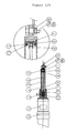
- Figure 1 shows the securing mechanism of a standard safety belt, side A (1a) and (1b) and the emergency uncoupling device as claimed, side B, existing of the following items: the seal (2), the securing mechanism (1b) with a flexible piston-rod fixed to the bottom part of the securing mechanism, provided with a take-away hook construction (8) at the end of the piston-rod (4).
- This take-away hook construction (8) fits into a claw-coupling (9) fixed to a piston (5), provided with calibrated holes (7) and a mounted sealing ring (13), surrounded by a predetermined viscous liquid (6) in a cylinder housing (3).
- the uncoupling-cone (11) and the sealing ring (12), for sealing the flexible piston-rod (4), are constructed at the end part of the cylinder housing (3) connected to side A. Grooves (14) are made along the inside of the last part of the cylinder housing (3).
- the cylinder housing (3) secured to the chassis of a vehicle (16) by means of a fastening bolt (15a) and a nut (15b).
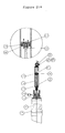
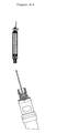
- Figures 2,3 and 4 show the working as follows: Under normal circumstances, only the standard safety belt mechanisms (1a) and (1b) will be used. The forces of the safety belt will be transferred through the safety belt mechanisms (1a) and (1b), the parts (2) and (3) of the uncoupling device, the fastening bolt (15a)and nut (15b) to the chassis of a vehicle (16).
Landscapes
- Engineering & Computer Science (AREA)
- Mechanical Engineering (AREA)
- Automotive Seat Belt Assembly (AREA)
- Fluid-Damping Devices (AREA)
Abstract
The above mentioned uncoupling has a predefined releasing distance, which will have the effect that occupants can free themselves from critical positions and at the end of this releasing distance there will be a perceptible acceleration in the movement as a signal for definite uncoupling. The distance and the time of this uncoupling moment will be variable and predetermined by the producer. The purpose of the so called perceptible acceleration will have its effect on the occupants by tighten there grip on the safety belt, preventing them from spontaneously falling down or side wards and becoming injured with possible unconsciousness.

Description
- The present invention relates to a device for quick, safe and easy uncoupling a safety belt of a vehicle in a state of emergency.
- Ordinary safety belts are commonly known and for instance placed, by regulation, in cars and busses.
- A disadvantage of these ordinary safety belts is the fact that, after a crash, where the vehicle comes at is side or roof, the occupant(s), more likely, ends up hanging in these so called safety belts. The force created, on the release part of the fastening side of the safety belt, is so enormous that in many cases it is impossible to unbolt the safety belt, which of course is not the meaning of a safety belt, especially in case of fire or drowning after the crash.
- A second disadvantage of these safety belts is the fact that, after for instance a proper unbolting by the occupants or after cutting their self loose, the chance of getting a serious head injury by falling down can not be ruled out, with a possible unconsciousness as a result. The possible fall in a truck for instance, can be down to two meters, in case of head down and body up the above mentioned unconsciousness is even more likely to happen.
It is obvious that these cases are not desirable, especially in cases of emergency. - All safety belts are capable of protecting the occupants during the crash, but none of the safety belts provides a quick and safe unbolting after the crash in different circumstances.
- According to this invention there is provided a device for uncoupling a safety belt in a vehicle after a crash of a vehicle of any kind, remarking the fact that the importance of the invention will increase by the relation between the size of the fall of the occupants and the size of the vehicle.
- The solution and all other characteristics of this invention are mentioned and described in the content of the patent claims below and its advantages are more clear from the following description, with reference to the accompanying drawings, which illustrate preferred embodiments of the invention, without restricting the scope of the inventive concept.
- The effect of the invention is based on the usage of an extra uncoupling mechanism, mounted between a standard safety belt release device and the chassis or other logic mounting part of the vehicle. This so called emergency release mechanism has been provided with a seal, which after breaking the seal, in case of an emergency, will start a slackening release of the safety belt.
The above mentioned uncoupling has a predefined releasing distance, which will have the effect that occupants can free themselves from critical positions and at the end of this releasing distance there will be a perceptible acceleration in the movement as a signal for definite uncoupling. The distance and the time of this uncoupling moment will be variable and predetermined by the producer. The purpose of the so called perceptible acceleration will have its effect on the occupants by tighten there grip on the safety belt, preventing them from spontaneously falling down or side wards and becoming injured with possible unconsciousness.
An embodiment of the invention is hereafter described and shown in the drawings.
The drawings show: - Figure 1
- a cross-section of the emergency uncoupling device in a sealed state
- Figure 2
- a cross-section of the emergency uncoupling device with a broken seal in the first stage
- Figure 3
- a cross-section of the emergency uncoupling device with a broken seal in the second stage
- Figure 4
- a cross-section of the emergency uncoupling device with a broken seal in the last and uncoupled stage
- Figure 1 shows the securing mechanism of a standard safety belt, side A (1a) and (1b) and the emergency uncoupling device as claimed, side B, existing of the following items:
the seal (2), the securing mechanism (1b) with a flexible piston-rod fixed to the bottom part of the securing mechanism, provided with a take-away hook construction (8) at the end of the piston-rod (4). This take-away hook construction (8) fits into a claw-coupling (9) fixed to a piston (5), provided with calibrated holes (7) and a mounted sealing ring (13), surrounded by a predetermined viscous liquid (6) in a cylinder housing (3). The uncoupling-cone (11) and the sealing ring (12), for sealing the flexible piston-rod (4), are constructed at the end part of the cylinder housing (3) connected to side A. Grooves (14) are made along the inside of the last part of the cylinder housing (3). The cylinder housing (3) secured to the chassis of a vehicle (16) by means of a fastening bolt (15a) and a nut (15b).
Figures 2,3 and 4 show the working as follows:
Under normal circumstances, only the standard safety belt mechanisms (1a) and (1b) will be used. The forces of the safety belt will be transferred through the safety belt mechanisms (1a) and (1b), the parts (2) and (3) of the uncoupling device, the fastening bolt (15a)and nut (15b) to the chassis of a vehicle (16). In case of an emergency, where the vehicle rolls over to its side or top, an enormous force will be present at the standard safety belt mechanisms (1a) and (1b) and as a result the securing mechanism (1b) will not open properly. After breaking the seal (2), Figure 2, the force of the belt will not be transferred to the chassis (16) any longer, but will be transferred to the flexible piston-rod (4) instead. Influenced by the force of the belt the piston (5) moves to the left in the picture, during stage 1, and the compressed viscous liquid (6) slides, through the calibrated holes (7), detail drawing Figure 2, into the compartment behind the piston (5). During the second stage, Figure 3, the viscous liquid (6) will slide even faster behind the piston (5), by means of the grooves (14)along the inside of the last part of the cylinder housing (3),which, as a result, will accelerate the speed of the movement. This is the perceptive part of the movement and it will indicate the opening of the device, which will result in a natural tight grip on the belt to prevent falling down or side wards.
The piston (5) is by means of a claw-coupling (9) hooked to a take-away hook construction (8). By coming to the end of the cylinder housing (3), the claws of the claw-coupling (9) will be forced open by the uncoupling-cone (11), detail drawing Figure 3. The attachment between the flexible piston-rod (4) and the piston (5) will be permanent separated. This will final the whole process of uncoupling in a state of emergency, Figure 4.
Claims (7)
- a Device for quick, safe and easy uncoupling a safety belt of a vehicle in a state of emergency, characterised in that the securing mechanism of the safety belt exposed to extreme forces of the belt, is still being able to uncouple and wherein it can fully integrate into the existing safety belt constructions as known in the market.
- a Device according to claim 1., characterised in that the seal (2) can be broken once.
- a Device according to any one of the preceding claims, characterised in that the calibration of the holes (7) can be variable.
- a Device according to any one of the preceding claims, characterised in that the time of uncoupling process can be variable.
- a Device according to any one of the preceding claims, characterised in that the piston-rod (4) is variable in flexibility in every direction.
- a Device according to any one of the preceding claims, wherein grooves (14) along the inside of the last part of the cylinder housing (3) are creating a acceleration of the movement at the end stage, with the purpose of creating a perceptive part of the movement resulting in a tight grip on the safety belt, during the permanent separation of the device.
- a Device according to any one of the preceding claims, characterised in that it can be uncoupled in every thinkable direction, mounted in a vehicle of any kind.
Applications Claiming Priority (1)
| Application Number | Priority Date | Filing Date | Title |
|---|---|---|---|
| NL1028610A NL1028610C1 (en) | 2005-03-23 | 2005-03-23 | Device for releasing a safety belt in an emergency situation. |
Publications (2)
| Publication Number | Publication Date |
|---|---|
| EP1705080A2 true EP1705080A2 (en) | 2006-09-27 |
| EP1705080A3 EP1705080A3 (en) | 2007-02-28 |
Family
ID=36699335
Family Applications (1)
| Application Number | Title | Priority Date | Filing Date |
|---|---|---|---|
| EP06075673A Withdrawn EP1705080A3 (en) | 2005-03-23 | 2006-03-23 | Unit to unbolt a safety belt in a state of emergency |
Country Status (2)
| Country | Link |
|---|---|
| EP (1) | EP1705080A3 (en) |
| NL (1) | NL1028610C1 (en) |
Family Cites Families (4)
| Publication number | Priority date | Publication date | Assignee | Title |
|---|---|---|---|---|
| FR2541954A1 (en) * | 1983-03-02 | 1984-09-07 | Laporte Eugene | Car safety belt locking buckle |
| ES8706315A1 (en) * | 1986-03-25 | 1987-06-16 | Arnau Fernandez Mayoralas Joaq | Safety belt arrangement |
| DE3905525A1 (en) * | 1989-02-23 | 1990-08-30 | Wilhelm Hans Juergen | Belt release system |
| DE20018091U1 (en) * | 2000-10-23 | 2001-03-08 | Trw Repa Gmbh | Vehicle occupant protection system |
-
2005
- 2005-03-23 NL NL1028610A patent/NL1028610C1/en not_active IP Right Cessation
-
2006
- 2006-03-23 EP EP06075673A patent/EP1705080A3/en not_active Withdrawn
Non-Patent Citations (1)
| Title |
|---|
| None |
Also Published As
| Publication number | Publication date |
|---|---|
| EP1705080A3 (en) | 2007-02-28 |
| NL1028610C1 (en) | 2006-09-27 |
Similar Documents
| Publication | Publication Date | Title |
|---|---|---|
| US5887897A (en) | Apparatus for pretensioning a vehicular seat belt | |
| EP2143962B1 (en) | Connecting device arranged in a motor vehicle and a method for controlling the same | |
| EP0059643B1 (en) | Dual spool pre-tensioner | |
| HU213434B (en) | Automotive vehicle including a security arrangement provided with an inflatable protective bag | |
| US7490854B2 (en) | Air bag system and method | |
| CA1038832A (en) | Vehicle safety belt systems | |
| US20070118952A1 (en) | Inflating and separating device of body protection airbags | |
| US7721837B1 (en) | Tethered separable occupational safety cage for transportation vehicles | |
| US9004531B1 (en) | Releasable tether retention system | |
| US20170106833A1 (en) | Load indicators for personal restraint systems and associated systems and methods | |
| EP1705080A2 (en) | Unit to unbolt a safety belt in a state of emergency | |
| US20030067188A1 (en) | Rescue system for a transport system | |
| US7681913B2 (en) | Air bag system | |
| US20120193899A1 (en) | Protective device for protecting an occupant of a vehicle, a seat, and an associated vehicle | |
| EP2360066A1 (en) | Retention system with belt tensioner and airbag | |
| EP3401197B1 (en) | Airbag system for a ride-on motor vehicle and method for retrofitting a ride-on motor vehicle | |
| US20180056934A1 (en) | Resettable Load-Limiting Adaptive Seatbelt Apparatus | |
| KR100882202B1 (en) | Electric buckle pretensioner for seat belt device | |
| US12145525B2 (en) | Fastening device for a vehicle interior lining, arrangement of a fastening device, airbag module and method for opening an airbag | |
| US20070085312A1 (en) | Airbag module with inflation control | |
| KR100579730B1 (en) | Pillar trim coupling structure of car curtain airbag | |
| CN201769782U (en) | Safety belt controller and safety belt device using same | |
| KR0149086B1 (en) | Energy absorbing device of a buckle anchor | |
| KR0157814B1 (en) | Energy absorbing device for a vehicle seat belt | |
| KR100239647B1 (en) | Safety seat belt device in vehicle |
Legal Events
| Date | Code | Title | Description |
|---|---|---|---|
| PUAI | Public reference made under article 153(3) epc to a published international application that has entered the european phase |
Free format text: ORIGINAL CODE: 0009012 |
|
| AK | Designated contracting states |
Kind code of ref document: A2 Designated state(s): AT BE BG CH CY CZ DE DK EE ES FI FR GB GR HU IE IS IT LI LT LU LV MC NL PL PT RO SE SI SK TR |
|
| AX | Request for extension of the european patent |
Extension state: AL BA HR MK YU |
|
| PUAL | Search report despatched |
Free format text: ORIGINAL CODE: 0009013 |
|
| AK | Designated contracting states |
Kind code of ref document: A3 Designated state(s): AT BE BG CH CY CZ DE DK EE ES FI FR GB GR HU IE IS IT LI LT LU LV MC NL PL PT RO SE SI SK TR |
|
| AX | Request for extension of the european patent |
Extension state: AL BA HR MK YU |
|
| AKX | Designation fees paid | ||
| REG | Reference to a national code |
Ref country code: DE Ref legal event code: 8566 |
|
| STAA | Information on the status of an ep patent application or granted ep patent |
Free format text: STATUS: THE APPLICATION IS DEEMED TO BE WITHDRAWN |
|
| 18D | Application deemed to be withdrawn |
Effective date: 20070829 |