EP1705035A1 - Pneumatic tire - Google Patents
Pneumatic tire Download PDFInfo
- Publication number
- EP1705035A1 EP1705035A1 EP04807952A EP04807952A EP1705035A1 EP 1705035 A1 EP1705035 A1 EP 1705035A1 EP 04807952 A EP04807952 A EP 04807952A EP 04807952 A EP04807952 A EP 04807952A EP 1705035 A1 EP1705035 A1 EP 1705035A1
- Authority
- EP
- European Patent Office
- Prior art keywords
- bead core
- fastening
- carcass layer
- fastening bead
- tire
- Prior art date
- Legal status (The legal status is an assumption and is not a legal conclusion. Google has not performed a legal analysis and makes no representation as to the accuracy of the status listed.)
- Withdrawn
Links
Images


Classifications
-
- B—PERFORMING OPERATIONS; TRANSPORTING
- B60—VEHICLES IN GENERAL
- B60C—VEHICLE TYRES; TYRE INFLATION; TYRE CHANGING; CONNECTING VALVES TO INFLATABLE ELASTIC BODIES IN GENERAL; DEVICES OR ARRANGEMENTS RELATED TO TYRES
- B60C15/00—Tyre beads, e.g. ply turn-up or overlap
- B60C15/0009—Tyre beads, e.g. ply turn-up or overlap features of the carcass terminal portion
- B60C15/0081—Tyre beads, e.g. ply turn-up or overlap features of the carcass terminal portion the carcass plies folded around or between more than one bead core
-
- B—PERFORMING OPERATIONS; TRANSPORTING
- B60—VEHICLES IN GENERAL
- B60C—VEHICLE TYRES; TYRE INFLATION; TYRE CHANGING; CONNECTING VALVES TO INFLATABLE ELASTIC BODIES IN GENERAL; DEVICES OR ARRANGEMENTS RELATED TO TYRES
- B60C15/00—Tyre beads, e.g. ply turn-up or overlap
- B60C15/04—Bead cores
- B60C15/05—Bead cores multiple, i.e. with two or more cores in each bead
-
- Y—GENERAL TAGGING OF NEW TECHNOLOGICAL DEVELOPMENTS; GENERAL TAGGING OF CROSS-SECTIONAL TECHNOLOGIES SPANNING OVER SEVERAL SECTIONS OF THE IPC; TECHNICAL SUBJECTS COVERED BY FORMER USPC CROSS-REFERENCE ART COLLECTIONS [XRACs] AND DIGESTS
- Y10—TECHNICAL SUBJECTS COVERED BY FORMER USPC
- Y10T—TECHNICAL SUBJECTS COVERED BY FORMER US CLASSIFICATION
- Y10T152/00—Resilient tires and wheels
- Y10T152/10—Tires, resilient
- Y10T152/10495—Pneumatic tire or inner tube
- Y10T152/10819—Characterized by the structure of the bead portion of the tire
-
- Y—GENERAL TAGGING OF NEW TECHNOLOGICAL DEVELOPMENTS; GENERAL TAGGING OF CROSS-SECTIONAL TECHNOLOGIES SPANNING OVER SEVERAL SECTIONS OF THE IPC; TECHNICAL SUBJECTS COVERED BY FORMER USPC CROSS-REFERENCE ART COLLECTIONS [XRACs] AND DIGESTS
- Y10—TECHNICAL SUBJECTS COVERED BY FORMER USPC
- Y10T—TECHNICAL SUBJECTS COVERED BY FORMER US CLASSIFICATION
- Y10T152/00—Resilient tires and wheels
- Y10T152/10—Tires, resilient
- Y10T152/10495—Pneumatic tire or inner tube
- Y10T152/10819—Characterized by the structure of the bead portion of the tire
- Y10T152/10846—Bead characterized by the chemical composition and or physical properties of elastomers or the like
Definitions
- the present invention relates to a pneumatic tire and, more specifically, to a pneumatic tire capable of drastically reducing an eccentric fitting amount relative to a rim.
- a carcass layer of a pneumatic tire is configured to be fastened by folding both ends respectively around a pair of left and right bead cores.
- a carcass layer of a pneumatic tire is configured to be fastened by folding both ends respectively around a pair of left and right bead cores.
- the carcass layer is formed by winding a belt-shaped carcass material in a circumferential direction of the tire and then by splicing the both ends to be overlapped. Accordingly, such spliced portions constitute highly rigid bumps on an inner circumferential surface (an inner diameter side) of each of the bead cores, which is almost formed into a completely round shape. Such bumps would increase a primary eccentric fitting component when the tire is mounted on a rim, and may sometimes cause abnormal vibration when a vehicle is running.
- Patent Documents 1 and 2 it is possible to prevent protrusion of the bumps of the spliced portions on the inner circumferential surface of the bead core by means of splitting the bead core in two and interposing the end of the carcass layer therebetween instead of folding the end around the bead core.
- an unvulcanized tire simply configured to interpose the end of the carcass layer between the split portions of the bead core is subjected to vulcanization with a bladder inflation type vulcanizer, the end of the carcass layer may sometimes be pulled out of the bead core when the unvulcanized tire is pushed upward by the bladder.
- Patent Document 1 Japanese unexamined patent publication No. 6(1994) - 171306
- Patent Document 2 Japanese unexamined patent publication No. 7(1995) - 215006
- Patent Document 3 Japanese unexamined patent publication No. 62(1987) - 270308
- An object of the present invention is to provide a pneumatic tire for solving the foregoing problem, which is capable of reducing an eccentric fitting amount relative to a rim without causing a cost increase.
- the present invention provides a pneumatic tire composed of a carcass layer crossing between a pair of left and right bead cores, in which the bead cores comprise a fastening bead core for fastening an end of the carcass layer to be turned up around the fastening bead core, and a non-fastening bead core free from the end of the carcass layer.
- an inner circumferential radius R 2 of the non-fastening bead core is set smaller than an inner circumferential radius R 1 of the end of the carcass layer to be turned up around the fastening bead core.
- the bead core is split into the fastening bead core for fastening the end of the carcass layer and the non-fastening bead core free from fastening.
- the inner circumferential radius R 2 of the non-fastening bead core is set smaller than the inner circumferential radius R 1 of the end of the carcass layer to be turned up.
- the fastening bead core is mainly used for fastening the end of the carcass layer to be turned up and does not contribute to the engagement with the rim by constriction. Therefore, the primary eccentric fitting component attributable to the spliced portions of the carcass layer is substantially eliminated, and the eccentric fitting amount relative to the rim is thereby reduced. It is possible to reduce abnormal vibration when a vehicle is running.
- the ends of the carcass layer are fastened to be turned up around the fastening bead cores. Accordingly, it is possible to vulcanize a green tire by use of the bladder inflation type of vulcanizer, and thereby to manufacture the tire without practically causing a cost increase.
- Fig. 1 is a half sectional view showing a pneumatic tire according to an embodiment of the present invention
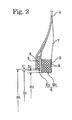
- Fig. 2 is an explanatory view showing a substantial part around a bead portion thereof.
- reference numeral 1 denotes a tread portion and sidewall portions 2 and bead portions 3 are continuously formed on both sides of this tread portion 1.
- the pneumatic tire T is mounted by fitting the bead portions 3 on a rim R.
- a carcass layer 4 is provided inside the tire, and two-layered belt layers 5 are provided on an outer circumferential side of this carcass layer 4 at the tread portion 1.
- the carcass layer 4 is arranged so as to spread over the tread portion 1, the sidewall portions 2, and the bead portions 3, and both ends of the carcass layer 4 are fastened to bead cores 6 buried in the bead portions 3.
- the bead core 6 is formed into an annular body having an almost completely round shape which extends around the tire. Moreover, as shown in Fig. 2 in detail, the bead cores 6 are composed of a fastening bead core 6a for fastening an end of the carcass layer 4 to be turned up around the fastening bead core from the inside to the outside of the tire, and a non-fastening bead core 6b which does not fasten the end of the carcass layer 4. A bead filler 7 made of hard rubber is provided on the outer circumference of the non-fastening bead core 6b.
- Each of the fastening bead core 6a and the non-fastening bead core 6b is formed by winding and overlapping bead wires 8 (steel wires), which are covered with insulation rubber 9, several times in the circumferential direction of the tire.
- the fastening bead core 6a and the non-fastening bead core 6b are formed in mutually different inner diameters.
- an inner circumferential radius R 2 of the non-fastening bead core 6b is set smaller than an inner circumferential radius R 1 ' of the fastening bead core 6a and smaller than an inner circumferential radius R 1 of the end of the carcass layer 4 to be turned up around the fastening bead core 6a.
- the fastening bead core 6a and the non-fastening bead core 6b are constituted such that the inner circumferential radius R 2 of the non-fastening bead core 6b is set smaller than the inner circumferential radius R 1 of the end of the carcass layer 4 in the fastening bead core 6a. Accordingly, the fastening bead core 6a solely contributes to action to fasten the end of the carcass layer 4. On the contrary, the non-fastening bead core 6b solely acts to perform engagement with the rim R by constriction.
- arrangement of the fastening bead core 6a and the non-fastening bead core 6b is not limited to the layout shown in Fig. 2, as long as the relation between the inner circumferential radius R 2 of the non-fastening bead core 6b and the inner circumferential radius R 1 of the end of the carcass layer 4 is retained as described above.
- the effect to suppress abnormal vibration is reduced if the difference ⁇ is smaller than 0.5 times of the thickness t.
- Dimensions of the fastening bead core solely contributing to fastening the end of the carcass layer are preferably set to the width in the axial direction of the tire in the range from 1 to 3 mm, and the width in the diametric direction of the tire in the range from 4 to 12 mm in terms of the cross section. Moreover, it is preferable to set total tension strength of the fastening bead core equal to or greater than 5 kN. It is possible to support tension of the carcass layer stably by setting the total tension strength equal to or greater than 5 kN.
- the total tension strength equal to or greater than 5 kN if the width of the fastening bead core in the axial direction of the tire is below 1 mm or the width in the diametric direction of the tire is below 4 mm.
- a region for arranging the non-fastening bead core will be reduced if the width in the axial direction of the tire exceeds 3 mm or the width in the diametric direction of the tire exceeds 12 mm.
- Such designs may reduce fitting pressure, or adversely affect rigidity of sides of the tire and deteriorate ride comfort.
- an upper limit of the total tension strength of the fastening bead core is not particularly limited, it is recommended to set the upper limit to about 10 kN in terms of usefulness.
- the total tension strength means tension strength of the bead core measured with a tension testing machine, in a state where the bead core is cut open while preserving the arrangement of the cords.
- the insulation rubber for covering the steel cords of the fastening bead core may be the same as the insulation rubber for the non-fastening bead core.
- the insulation rubber for the fastening bead core be relatively harder than the insulation rubber for the non-fastening bead core.
- the hardness of the insulation rubber for the fastening bead core is set preferably in the range from 60 to 98 in terms of JIS-A hardness, or more preferably in the range from 75 to 98. Meanwhile, the thickness thereof is preferably set in the range from 0.1 to 1.5 mm.
- the above-described present invention is suitable for application to a pneumatic radial tire. However, it is needless to say that the present invention is also applicable to a bias tire.
- Examples 1 and 2 Two types of pneumatic radial tires (Examples 1 and 2) were fabricated by setting the tire size as 205/65R15 and applying the tire structure as shown in Fig. 1 while providing one carcass layer in common. Meanwhile, the thickness t of the carcass layer, the difference (t+ ⁇ ) between the inner circumferential radius R 1 ' of the fastening bead core and the inner circumferential radius R 2 of the non-fastening bead core, and the difference ⁇ between the inner circumferential radius R 1 of the end of the carcass layer to be turned up around the fastening bead core and the inner circumferential radius R 2 of the non-fastening bead core (a radial difference after turning up) are changed between these tires as shown in Table 1.
- a radial tire having a conventional structure was fabricated by applying the same tire size as above.
- this tire was different from the above-mentioned tires in that the two types of the bead cores in the tire structure shown in Fig. 1 were incorporated and that the end of the carcass layer was folded and fastened to the incorporated bead cores from the inside to the outside.
Landscapes
- Engineering & Computer Science (AREA)
- Mechanical Engineering (AREA)
- Tires In General (AREA)
- Tyre Moulding (AREA)
Abstract
In a pneumatic tire composed of a carcass layer crossing between a pair of left and right bead cores, the bead cores comprise a fastening bead core for fastening an end of the carcass layer to be turned up around the fastening bead core, and a non-fastening bead core free from the end of the carcass layer. An inner circumferential radius R2 of the non-fastening bead core is set smaller than an inner circumferential radius R1 of the end of the carcass layer to be turned up around the fastening bead core.
Description
- The present invention relates to a pneumatic tire and, more specifically, to a pneumatic tire capable of drastically reducing an eccentric fitting amount relative to a rim.
- Generally, a carcass layer of a pneumatic tire is configured to be fastened by folding both ends respectively around a pair of left and right bead cores. In this way, by fastening the carcass layer by folding the both ends thereof around the bead cores, it is possible to avoid the ends of the carcass layer from being pulled out of the bead cores when an unvulcanized tire is pressed against an inner surface of a mold from inside by inflating a bladder during vulcanization forming, and to provide carcass cords with uniform tension in order to improve uniformity of the tire.
- However, the carcass layer is formed by winding a belt-shaped carcass material in a circumferential direction of the tire and then by splicing the both ends to be overlapped. Accordingly, such spliced portions constitute highly rigid bumps on an inner circumferential surface (an inner diameter side) of each of the bead cores, which is almost formed into a completely round shape. Such bumps would increase a primary eccentric fitting component when the tire is mounted on a rim, and may sometimes cause abnormal vibration when a vehicle is running.
- Concerning this problem, as disclosed in Patent Documents 1 and 2, it is possible to prevent protrusion of the bumps of the spliced portions on the inner circumferential surface of the bead core by means of splitting the bead core in two and interposing the end of the carcass layer therebetween instead of folding the end around the bead core. However, when an unvulcanized tire simply configured to interpose the end of the carcass layer between the split portions of the bead core is subjected to vulcanization with a bladder inflation type vulcanizer, the end of the carcass layer may sometimes be pulled out of the bead core when the unvulcanized tire is pushed upward by the bladder. For this reason, it is not possible to employ the vulcanizing method utilizing the bladder inflation for vulcanizing this pneumatic tire. Instead, it is necessary to employ a method of assembling the unvulcanized tire on a surface of a rigid core mold and subjecting the assembled unvulcanized tire directly to thermal vulcanization as disclosed in
Patent Document 3. - Nevertheless, in the vulcanizing method using the rigid core mold, it is necessary to form the unvulcanized tire so as to strictly equalize the tension among the carcass cords on the surface of the rigid core mold. Otherwise, widths of ends of the carcass cords to be interposed between the split portions of the bead core may become uneven after thermal contraction of the cords, and uniformity of the tire is thereby deteriorated. Accordingly, this method requires tremendous operations for managing the tension of the carcass cords. As a result, overall operability is substantially reduced and manufacturing costs are increased.
- (Patent Document 1)
Japanese unexamined patent publication No. 6(1994) - 171306 - (Patent Document 2)
Japanese unexamined patent publication No. 7(1995) - 215006 - (Patent Document 3)
Japanese unexamined patent publication No. 62(1987) - 270308 - An object of the present invention is to provide a pneumatic tire for solving the foregoing problem, which is capable of reducing an eccentric fitting amount relative to a rim without causing a cost increase.
- To attain the object, the present invention provides a pneumatic tire composed of a carcass layer crossing between a pair of left and right bead cores, in which the bead cores comprise a fastening bead core for fastening an end of the carcass layer to be turned up around the fastening bead core, and a non-fastening bead core free from the end of the carcass layer. Here, an inner circumferential radius R2 of the non-fastening bead core is set smaller than an inner circumferential radius R1 of the end of the carcass layer to be turned up around the fastening bead core.
- According to the present invention, the bead core is split into the fastening bead core for fastening the end of the carcass layer and the non-fastening bead core free from fastening. Moreover, the inner circumferential radius R2 of the non-fastening bead core is set smaller than the inner circumferential radius R1 of the end of the carcass layer to be turned up. Accordingly, whereas the non-fastening bead core is mainly used for engagement with the rim by constriction, the fastening bead core is mainly used for fastening the end of the carcass layer to be turned up and does not contribute to the engagement with the rim by constriction. Therefore, the primary eccentric fitting component attributable to the spliced portions of the carcass layer is substantially eliminated, and the eccentric fitting amount relative to the rim is thereby reduced. It is possible to reduce abnormal vibration when a vehicle is running.
- Moreover, the ends of the carcass layer are fastened to be turned up around the fastening bead cores. Accordingly, it is possible to vulcanize a green tire by use of the bladder inflation type of vulcanizer, and thereby to manufacture the tire without practically causing a cost increase.
-
- Fig. 1 is a half sectional view showing a pneumatic tire according to an embodiment of the present invention.
- Fig. 2 is an explanatory view showing a substantial part of a bead portion of the pneumatic tire of Fig. 1.
- Fig. 3 is an explanatory view showing a substantial part of a bead portion according to another embodiment of the present invention.
- Fig.4 is an explanatory view showing a substantial part of a bead portion according to still another embodiment of the present invention.
- Now, the present invention will be described more concretely with reference to preferred embodiments shown in the accompanying drawings.
- Fig. 1 is a half sectional view showing a pneumatic tire according to an embodiment of the present invention, and Fig. 2 is an explanatory view showing a substantial part around a bead portion thereof.
- In a pneumatic tire T shown in Fig. 1, reference numeral 1 denotes a tread portion and sidewall portions 2 and bead
portions 3 are continuously formed on both sides of this tread portion 1. The pneumatic tire T is mounted by fitting thebead portions 3 on a rim R. A carcass layer 4 is provided inside the tire, and two-layered belt layers 5 are provided on an outer circumferential side of this carcass layer 4 at the tread portion 1. The carcass layer 4 is arranged so as to spread over the tread portion 1, the sidewall portions 2, and thebead portions 3, and both ends of the carcass layer 4 are fastened to beadcores 6 buried in thebead portions 3. - The
bead core 6 is formed into an annular body having an almost completely round shape which extends around the tire. Moreover, as shown in Fig. 2 in detail, thebead cores 6 are composed of afastening bead core 6a for fastening an end of the carcass layer 4 to be turned up around the fastening bead core from the inside to the outside of the tire, and anon-fastening bead core 6b which does not fasten the end of the carcass layer 4. Abead filler 7 made of hard rubber is provided on the outer circumference of thenon-fastening bead core 6b. - Each of the fastening bead
core 6a and thenon-fastening bead core 6b is formed by winding and overlapping bead wires 8 (steel wires), which are covered withinsulation rubber 9, several times in the circumferential direction of the tire. The fastening beadcore 6a and thenon-fastening bead core 6b are formed in mutually different inner diameters. Specifically, an inner circumferential radius R2 of thenon-fastening bead core 6b is set smaller than an inner circumferential radius R1' of thefastening bead core 6a and smaller than an inner circumferential radius R1 of the end of the carcass layer 4 to be turned up around the fasteningbead core 6a. Here, assuming that the thickness of the carcass layer 4 is t, the inner circumferential radius R1 of the end of the carcass layer 4 satisfies a relation of R1= R1' ― nt (n is the number of carcass layers). - As described above, the fastening bead
core 6a and thenon-fastening bead core 6b are constituted such that the inner circumferential radius R2 of thenon-fastening bead core 6b is set smaller than the inner circumferential radius R1 of the end of the carcass layer 4 in the fasteningbead core 6a. Accordingly, thefastening bead core 6a solely contributes to action to fasten the end of the carcass layer 4. On the contrary, thenon-fastening bead core 6b solely acts to perform engagement with the rim R by constriction. Therefore, when the pneumatic tire T is mounted on the rim R, an amount that a spliced portion of the carcass layer 4 protrudes out of the inner diameter of thenon-fastening bead core 6b is reduced or even eliminated. In this way, it is possible to set a primary eccentric fitting component substantially to zero, and thereby to reduce abnormal vibration when a vehicle is running. - In the present invention, arrangement of the
fastening bead core 6a and thenon-fastening bead core 6b is not limited to the layout shown in Fig. 2, as long as the relation between the inner circumferential radius R2 of thenon-fastening bead core 6b and the inner circumferential radius R1 of the end of the carcass layer 4 is retained as described above. For example, as in an embodiment shown in Fig. 3, it is possible to place the fasteningbead core 6a in the middle while placing thenon-fastening bead cores 6b on both sides thereof in an axial direction of the tire. Alternatively, as in an embodiment shown in Fig. 4, it is also possible to place the fasteningbead core 6a outside thenon-fastening bead core 6b in terms of the axial direction of the tire. - Meanwhile, as exemplified in Figs. 2, 3, and 4, it is advantageous in light of the manufacturing process to set the folding direction of the end of the carcass layer 4 from the inside to the outside of the tire. However, it is also possible to fold the end of the carcass layer 4 from the outside to the inside when appropriate.
- In the present invention, in order to further improve the above-described effect of reducing the eccentric fitting amount, a difference δ (= R1 ― R2) between the inner circumferential radius R1 of the end of the carcass layer 4 to be folded at the fastening bead core 4a and the inner circumferential radius R2 of the
non-fastening bead core 6b is set preferably in the range from 0.5 to 1.5 times of the thickness t of the carcass layer 4, or more preferably in the range from 1.0 to 1.5 times thereof. The effect to suppress abnormal vibration is reduced if the difference δ is smaller than 0.5 times of the thickness t. On the contrary, if the difference δ is greater than 1.5 times of the thickness t, a contact area with the adjacent bead core annular body is reduced, thereby incurring deterioration of uniformity or an increase in weight attributable to an increase in a sectional width of the bead core annular body. - Dimensions of the fastening bead core solely contributing to fastening the end of the carcass layer are preferably set to the width in the axial direction of the tire in the range from 1 to 3 mm, and the width in the diametric direction of the tire in the range from 4 to 12 mm in terms of the cross section. Moreover, it is preferable to set total tension strength of the fastening bead core equal to or greater than 5 kN. It is possible to support tension of the carcass layer stably by setting the total tension strength equal to or greater than 5 kN.
- Here, it is difficult to set the total tension strength equal to or greater than 5 kN if the width of the fastening bead core in the axial direction of the tire is below 1 mm or the width in the diametric direction of the tire is below 4 mm. On the contrary, a region for arranging the non-fastening bead core will be reduced if the width in the axial direction of the tire exceeds 3 mm or the width in the diametric direction of the tire exceeds 12 mm. Such designs may reduce fitting pressure, or adversely affect rigidity of sides of the tire and deteriorate ride comfort.
- Although an upper limit of the total tension strength of the fastening bead core is not particularly limited, it is recommended to set the upper limit to about 10 kN in terms of usefulness. Here, the total tension strength means tension strength of the bead core measured with a tension testing machine, in a state where the bead core is cut open while preserving the arrangement of the cords.
- Moreover, the insulation rubber for covering the steel cords of the fastening bead core may be the same as the insulation rubber for the non-fastening bead core. However, it is preferable that the insulation rubber for the fastening bead core be relatively harder than the insulation rubber for the non-fastening bead core. By using the harder insulation rubber for the fastening bead core, it is possible to fasten the carcass layer even when a cross-sectional shape (a cross-sectional area) of the fastening bead core is smaller than that of the non-fastening bead core. The hardness of the insulation rubber for the fastening bead core is set preferably in the range from 60 to 98 in terms of JIS-A hardness, or more preferably in the range from 75 to 98. Meanwhile, the thickness thereof is preferably set in the range from 0.1 to 1.5 mm.
- The above-described present invention is suitable for application to a pneumatic radial tire. However, it is needless to say that the present invention is also applicable to a bias tire.
- Two types of pneumatic radial tires (Examples 1 and 2) were fabricated by setting the tire size as 205/65R15 and applying the tire structure as shown in Fig. 1 while providing one carcass layer in common. Meanwhile, the thickness t of the carcass layer, the difference (t+δ) between the inner circumferential radius R1' of the fastening bead core and the inner circumferential radius R2 of the non-fastening bead core, and the difference δ between the inner circumferential radius R1 of the end of the carcass layer to be turned up around the fastening bead core and the inner circumferential radius R2 of the non-fastening bead core (a radial difference after turning up) are changed between these tires as shown in Table 1.
- On the other hand, a radial tire having a conventional structure (Conventional Example) was fabricated by applying the same tire size as above. However, this tire was different from the above-mentioned tires in that the two types of the bead cores in the tire structure shown in Fig. 1 were incorporated and that the end of the carcass layer was folded and fastened to the incorporated bead cores from the inside to the outside.
- The eccentric fitting amounts of the three types of tires were measured in accordance with the following evaluation method. Results are shown in Table 1.
- Here, in terms of manufacturing costs of the tires, the tires of Examples 1 and 2 required slightly higher material costs than that of Conventional Example, because the bead cores were split in two. However, costs for vulcanization of these tires were almost equal.
- After mounting each tire for evaluation on a rim, air at regular inner pressure as defined in JATMA was filled therein. Then, differences in the distance between a rim check line and a rim flange were respectively measured in 16 positions evenly located in the circumferential direction, and a difference between the maximum value and the minimum value of the measured distances was obtained.
- The evaluation was carried out by use of inverse numbers of the measured values, and the values were expressed by index numbers while setting the inverse number of the measured value of the conventional tire as 100. Accordingly, as the index value becomes greater, the difference and the eccentric fitting amount become smaller.
Table 1 Conventional Example Example 1 Example 2 Thickness of Carcass Layer t (mm) 1.1 1.1 1.2 Difference in Inner Circumferential Radii of Bead Cores (R1' - R2) (mm) - 2.5 2.0 Difference in Inner Circumferential Radii after Turning up (R1 - R2) (mm) - 1.4 0.7 Eccentric Fitting Amount (Index) 100 150 130
Claims (6)
- A pneumatic tire composed of a carcass layer crossing between a pair of left and right bead cores, the bead cores comprising:a fastening bead core for fastening an end of the carcass layer to be turned up around the fastening bead core; anda non-fastening bead core free from the end of the carcass layer,wherein an inner circumferential radius R2 of the non-fastening bead core is set smaller than an inner circumferential radius R1 of the end of the carcass layer to be turned up around the fastening bead core.
- The pneumatic tire according to claim 1,
wherein a difference δ between the inner circumferential radius R1 of the end of the carcass layer to be turned up around the fastening bead core and the inner circumferential radius R2 of the non-fastening bead core is in the range from 0.5 to 1.5 times of the thickness t of the carcass layer. - The pneumatic tire according to any of claims 1 and 2,
wherein the width of the fastening bead core in an axial direction of the tire is in the range from 1 to 3 mm and the width of the fastening bead core in a diametric direction of the tire is in the range from 4 to 12 mm respectively in terms of a cross section of the fastening bead core, and
total tension strength of the fastening bead core is equal to or greater than 5 kN. - The pneumatic tire according to any of claims 1 to 3,
wherein insulation rubber for the fastening bead core has JIS-A hardness in the range from 60 to 98 and thickness in the range from 0.1 to 1.5 mm. - The pneumatic tire according to any of claims 1 to 4,
wherein the non-fastening bead cores are respectively placed on both sides of the fastening bead core in an axial direction of the tire. - The pneumatic tire according to any of claims 1 to 5,
wherein a bead filler is disposed only on a side of the non-fastening bead core out of the fastening bead core and the non-fastening bead core.
Applications Claiming Priority (2)
| Application Number | Priority Date | Filing Date | Title |
|---|---|---|---|
| JP2004001404A JP2005193758A (en) | 2004-01-06 | 2004-01-06 | Pneumatic tire |
| PCT/JP2004/019597 WO2005065971A1 (en) | 2004-01-06 | 2004-12-28 | Pneumatic tire |
Publications (2)
| Publication Number | Publication Date |
|---|---|
| EP1705035A1 true EP1705035A1 (en) | 2006-09-27 |
| EP1705035A4 EP1705035A4 (en) | 2008-09-03 |
Family
ID=34746986
Family Applications (1)
| Application Number | Title | Priority Date | Filing Date |
|---|---|---|---|
| EP04807952A Withdrawn EP1705035A4 (en) | 2004-01-06 | 2004-12-28 | Pneumatic tire |
Country Status (5)
| Country | Link |
|---|---|
| US (1) | US7575033B2 (en) |
| EP (1) | EP1705035A4 (en) |
| JP (1) | JP2005193758A (en) |
| CN (1) | CN100475568C (en) |
| WO (1) | WO2005065971A1 (en) |
Cited By (3)
| Publication number | Priority date | Publication date | Assignee | Title |
|---|---|---|---|---|
| DE102008004886A1 (en) | 2008-01-17 | 2009-07-23 | Continental Aktiengesellschaft | Vehicle tires |
| FR2956836A1 (en) * | 2010-02-26 | 2011-09-02 | Michelin Soc Tech | PNEUMATIC HAVING GREATER RESISTANCE TO DECOINCEMENT. |
| CN105437875A (en) * | 2014-09-23 | 2016-03-30 | 韩国轮胎株式会社 | Pneumatic tire |
Families Citing this family (6)
| Publication number | Priority date | Publication date | Assignee | Title |
|---|---|---|---|---|
| CN101979240B (en) * | 2010-09-29 | 2013-03-20 | 中国化工橡胶桂林有限公司 | Giant tire bead for oblique crossing engineering machinery tire and manufacturing method thereof |
| EP3138700B1 (en) * | 2014-04-28 | 2019-10-23 | Sumitomo Rubber Industries, Ltd. | Pneumatic tire |
| JP5932882B2 (en) * | 2014-05-14 | 2016-06-08 | 住友ゴム工業株式会社 | Pneumatic tire |
| JP2019098991A (en) * | 2017-12-05 | 2019-06-24 | Toyo Tire株式会社 | Green tire and manufacturing method of pneumatic tire |
| JP7245632B2 (en) * | 2018-10-31 | 2023-03-24 | 株式会社ブリヂストン | tire |
| JP7339503B2 (en) * | 2019-06-14 | 2023-09-06 | 横浜ゴム株式会社 | pneumatic tire |
Family Cites Families (17)
| Publication number | Priority date | Publication date | Assignee | Title |
|---|---|---|---|---|
| FR1127521A (en) | 1955-06-02 | 1956-12-18 | Mft Fr Pneumatiques Michelin | Improvement of tire beads |
| JPS58105806A (en) * | 1981-12-21 | 1983-06-23 | Yokohama Rubber Co Ltd:The | Pneumatic tire |
| FR2597783B1 (en) | 1986-04-25 | 1988-08-26 | Michelin & Cie | RIGID MOLD FOR MOLDING AND VULCANIZING TIRES |
| JPH05178033A (en) * | 1992-01-08 | 1993-07-20 | Toyo Tire & Rubber Co Ltd | Pneumatic tire |
| FR2715348A1 (en) | 1994-01-21 | 1995-07-28 | Sedepro | Anchoring the carcass of a tire. |
| FR2694521A1 (en) | 1992-08-05 | 1994-02-11 | Sedepro | Anchoring the carcass of a tire. |
| JPH06171322A (en) * | 1992-10-05 | 1994-06-21 | Bridgestone Corp | Pneumatic tire |
| JPH06191238A (en) * | 1992-12-25 | 1994-07-12 | Sumitomo Rubber Ind Ltd | Radial tires for passenger cars |
| FR2707561A1 (en) * | 1993-07-12 | 1995-01-20 | Michelin & Cie | Tire structure for heavy goods vehicles. |
| JPH08175126A (en) * | 1994-12-22 | 1996-07-09 | Yokohama Rubber Co Ltd:The | Pneumatic tire for heavy load |
| US5885387A (en) | 1995-12-08 | 1999-03-23 | Sumitomo Rubber Industries, Ltd. | Pneumatic tire having endless carcass cord ply |
| FR2763894A1 (en) * | 1997-05-30 | 1998-12-04 | Michelin & Cie | TIRE ENVELOPE WITH EACH TWO RODS IN EACH BUCKLE |
| JPH1128915A (en) * | 1997-07-14 | 1999-02-02 | Yokohama Rubber Co Ltd:The | Pneumatic tire and its forming method |
| DE19804295A1 (en) * | 1998-02-04 | 1999-08-05 | Continental Ag | Pneumatic vehicle tires with split carcass |
| JPH11301219A (en) * | 1998-04-15 | 1999-11-02 | Yokohama Rubber Co Ltd:The | Automotive peumatic tire |
| CN1226135C (en) * | 1998-10-30 | 2005-11-09 | 倍耐力轮胎公司 | Method for manufacturing a motor vehicle tire casing structure and tire casing structure obtained therefrom |
| JP2000301917A (en) * | 1999-04-19 | 2000-10-31 | Bridgestone Corp | Pneumatic radial tire for heavy load |
-
2004
- 2004-01-06 JP JP2004001404A patent/JP2005193758A/en active Pending
- 2004-12-28 WO PCT/JP2004/019597 patent/WO2005065971A1/en not_active Ceased
- 2004-12-28 EP EP04807952A patent/EP1705035A4/en not_active Withdrawn
- 2004-12-28 US US10/584,380 patent/US7575033B2/en not_active Expired - Fee Related
- 2004-12-28 CN CNB2004800399764A patent/CN100475568C/en not_active Expired - Fee Related
Cited By (5)
| Publication number | Priority date | Publication date | Assignee | Title |
|---|---|---|---|---|
| DE102008004886A1 (en) | 2008-01-17 | 2009-07-23 | Continental Aktiengesellschaft | Vehicle tires |
| FR2956836A1 (en) * | 2010-02-26 | 2011-09-02 | Michelin Soc Tech | PNEUMATIC HAVING GREATER RESISTANCE TO DECOINCEMENT. |
| US9358844B2 (en) | 2010-02-26 | 2016-06-07 | Compagnie Generale Des Etablissements Michelin | Tire with greater resistance to unseating |
| CN105437875A (en) * | 2014-09-23 | 2016-03-30 | 韩国轮胎株式会社 | Pneumatic tire |
| EP3000624A3 (en) * | 2014-09-23 | 2016-07-06 | Hankook Tire Co., Ltd. | Pneumatic tire |
Also Published As
| Publication number | Publication date |
|---|---|
| EP1705035A4 (en) | 2008-09-03 |
| CN100475568C (en) | 2009-04-08 |
| CN1902062A (en) | 2007-01-24 |
| WO2005065971A1 (en) | 2005-07-21 |
| JP2005193758A (en) | 2005-07-21 |
| US20070163696A1 (en) | 2007-07-19 |
| US7575033B2 (en) | 2009-08-18 |
Similar Documents
| Publication | Publication Date | Title |
|---|---|---|
| EP1559535B1 (en) | Pneumatic tire and method of manufacturing the same | |
| US7476285B2 (en) | Motorcycle tires and method of producing the same | |
| EP1621328A2 (en) | Method of manufacturing a pneumatic tire | |
| JP6720539B2 (en) | Pneumatic tire | |
| US7575033B2 (en) | Pneumatic tire | |
| EP1859924B1 (en) | Method for producing pneumatic tire | |
| EP4112288B1 (en) | Pneumatic tyre and method for manufacturing the same | |
| US7975741B2 (en) | Pneumatic tire and producing method of pneumatic tire | |
| US7556704B2 (en) | Pneumatic tire and manufacturing method thereof | |
| EP3366496B1 (en) | Run flat tire and method for manufacturing same | |
| EP1690666B1 (en) | Method of manufacturing radial tire for a construction vehicle | |
| EP0426389B1 (en) | A pneumatic tyre | |
| EP2865547B1 (en) | Pneumatic tire | |
| JP2012076662A (en) | Pneumatic tire | |
| EP1782971B1 (en) | Tire for motorcycle | |
| US20150336426A1 (en) | Pneumatic Tire and Method for Manufacturing Pneumatic Tire | |
| US20060185780A1 (en) | Pneumatic tire for passenger cars | |
| US20180244113A1 (en) | Run flat tire and method for manufacturing same | |
| JP6369184B2 (en) | Rehabilitation tire | |
| EP1659001B1 (en) | Pneumatic tire | |
| CN113146894B (en) | Method for manufacturing tire and green tire | |
| JPH1058913A (en) | Manufacturing method of radial tire | |
| JP2024104232A (en) | Raw tire manufacturing method, pneumatic tire manufacturing method, raw tire manufacturing apparatus, and pneumatic tire | |
| KR100554972B1 (en) | Pneumatic tire with welded belt | |
| JP2008030660A (en) | Pneumatic tire and manufacturing method thereof |
Legal Events
| Date | Code | Title | Description |
|---|---|---|---|
| PUAI | Public reference made under article 153(3) epc to a published international application that has entered the european phase |
Free format text: ORIGINAL CODE: 0009012 |
|
| 17P | Request for examination filed |
Effective date: 20060706 |
|
| AK | Designated contracting states |
Kind code of ref document: A1 Designated state(s): FR IT |
|
| DAX | Request for extension of the european patent (deleted) | ||
| RBV | Designated contracting states (corrected) |
Designated state(s): FR IT |
|
| A4 | Supplementary search report drawn up and despatched |
Effective date: 20080804 |
|
| 17Q | First examination report despatched |
Effective date: 20081104 |
|
| GRAP | Despatch of communication of intention to grant a patent |
Free format text: ORIGINAL CODE: EPIDOSNIGR1 |
|
| STAA | Information on the status of an ep patent application or granted ep patent |
Free format text: STATUS: THE APPLICATION IS DEEMED TO BE WITHDRAWN |
|
| 18D | Application deemed to be withdrawn |
Effective date: 20100624 |