EP1704050B1 - Translucent, flame resistant composite materials - Google Patents
Translucent, flame resistant composite materials Download PDFInfo
- Publication number
- EP1704050B1 EP1704050B1 EP04817829.7A EP04817829A EP1704050B1 EP 1704050 B1 EP1704050 B1 EP 1704050B1 EP 04817829 A EP04817829 A EP 04817829A EP 1704050 B1 EP1704050 B1 EP 1704050B1
- Authority
- EP
- European Patent Office
- Prior art keywords
- mold
- minutes
- per square
- square inch
- layer
- Prior art date
- Legal status (The legal status is an assumption and is not a legal conclusion. Google has not performed a legal analysis and makes no representation as to the accuracy of the status listed.)
- Expired - Lifetime
Links
- 239000002131 composite material Substances 0.000 title claims description 66
- 239000000758 substrate Substances 0.000 claims description 53
- 239000000463 material Substances 0.000 claims description 51
- 229920000491 Polyphenylsulfone Polymers 0.000 claims description 46
- 238000000034 method Methods 0.000 claims description 36
- 239000003365 glass fiber Substances 0.000 claims description 32
- 239000002657 fibrous material Substances 0.000 claims description 28
- 238000001816 cooling Methods 0.000 claims description 13
- 238000012360 testing method Methods 0.000 claims description 12
- 238000010030 laminating Methods 0.000 claims description 5
- 238000002844 melting Methods 0.000 claims description 5
- 230000008018 melting Effects 0.000 claims description 5
- 238000005192 partition Methods 0.000 claims description 5
- 238000010943 off-gassing Methods 0.000 claims description 3
- 238000012805 post-processing Methods 0.000 claims description 3
- 238000005520 cutting process Methods 0.000 claims description 2
- 238000003856 thermoforming Methods 0.000 claims description 2
- 229920001169 thermoplastic Polymers 0.000 claims 4
- 239000004416 thermosoftening plastic Substances 0.000 claims 4
- 239000000835 fiber Substances 0.000 description 21
- 238000005470 impregnation Methods 0.000 description 8
- 238000003825 pressing Methods 0.000 description 8
- 230000005540 biological transmission Effects 0.000 description 4
- 239000003517 fume Substances 0.000 description 4
- 239000000779 smoke Substances 0.000 description 4
- 231100000331 toxic Toxicity 0.000 description 4
- 230000002588 toxic effect Effects 0.000 description 4
- 230000014759 maintenance of location Effects 0.000 description 3
- 229920005989 resin Polymers 0.000 description 3
- 239000011347 resin Substances 0.000 description 3
- 239000012815 thermoplastic material Substances 0.000 description 3
- 238000009413 insulation Methods 0.000 description 2
- 238000004519 manufacturing process Methods 0.000 description 2
- 239000004033 plastic Substances 0.000 description 2
- 238000007655 standard test method Methods 0.000 description 2
- 229920003295 Radel® Polymers 0.000 description 1
- 230000002411 adverse Effects 0.000 description 1
- 238000005452 bending Methods 0.000 description 1
- 230000015572 biosynthetic process Effects 0.000 description 1
- 230000015556 catabolic process Effects 0.000 description 1
- 230000003247 decreasing effect Effects 0.000 description 1
- 238000006731 degradation reaction Methods 0.000 description 1
- 238000013461 design Methods 0.000 description 1
- 239000011152 fibreglass Substances 0.000 description 1
- 239000011521 glass Substances 0.000 description 1
- 238000010348 incorporation Methods 0.000 description 1
- 239000012212 insulator Substances 0.000 description 1
- 238000003475 lamination Methods 0.000 description 1
- 239000000203 mixture Substances 0.000 description 1
- 238000012986 modification Methods 0.000 description 1
- 230000004048 modification Effects 0.000 description 1
- 229920000642 polymer Polymers 0.000 description 1
- 239000002994 raw material Substances 0.000 description 1
- 229910001220 stainless steel Inorganic materials 0.000 description 1
- 239000010935 stainless steel Substances 0.000 description 1
- 230000000153 supplemental effect Effects 0.000 description 1
- 229920005992 thermoplastic resin Polymers 0.000 description 1
Images




Classifications
-
- B—PERFORMING OPERATIONS; TRANSPORTING
- B32—LAYERED PRODUCTS
- B32B—LAYERED PRODUCTS, i.e. PRODUCTS BUILT-UP OF STRATA OF FLAT OR NON-FLAT, e.g. CELLULAR OR HONEYCOMB, FORM
- B32B27/00—Layered products comprising a layer of synthetic resin
- B32B27/04—Layered products comprising a layer of synthetic resin as impregnant, bonding, or embedding substance
-
- B—PERFORMING OPERATIONS; TRANSPORTING
- B32—LAYERED PRODUCTS
- B32B—LAYERED PRODUCTS, i.e. PRODUCTS BUILT-UP OF STRATA OF FLAT OR NON-FLAT, e.g. CELLULAR OR HONEYCOMB, FORM
- B32B27/00—Layered products comprising a layer of synthetic resin
- B32B27/06—Layered products comprising a layer of synthetic resin as the main or only constituent of a layer, which is next to another layer of the same or of a different material
- B32B27/08—Layered products comprising a layer of synthetic resin as the main or only constituent of a layer, which is next to another layer of the same or of a different material of synthetic resin
-
- B—PERFORMING OPERATIONS; TRANSPORTING
- B32—LAYERED PRODUCTS
- B32B—LAYERED PRODUCTS, i.e. PRODUCTS BUILT-UP OF STRATA OF FLAT OR NON-FLAT, e.g. CELLULAR OR HONEYCOMB, FORM
- B32B27/00—Layered products comprising a layer of synthetic resin
- B32B27/12—Layered products comprising a layer of synthetic resin next to a fibrous or filamentary layer
-
- B—PERFORMING OPERATIONS; TRANSPORTING
- B32—LAYERED PRODUCTS
- B32B—LAYERED PRODUCTS, i.e. PRODUCTS BUILT-UP OF STRATA OF FLAT OR NON-FLAT, e.g. CELLULAR OR HONEYCOMB, FORM
- B32B27/00—Layered products comprising a layer of synthetic resin
- B32B27/28—Layered products comprising a layer of synthetic resin comprising synthetic resins not wholly covered by any one of the sub-groups B32B27/30 - B32B27/42
-
- C—CHEMISTRY; METALLURGY
- C08—ORGANIC MACROMOLECULAR COMPOUNDS; THEIR PREPARATION OR CHEMICAL WORKING-UP; COMPOSITIONS BASED THEREON
- C08J—WORKING-UP; GENERAL PROCESSES OF COMPOUNDING; AFTER-TREATMENT NOT COVERED BY SUBCLASSES C08B, C08C, C08F, C08G or C08H
- C08J5/00—Manufacture of articles or shaped materials containing macromolecular substances
- C08J5/04—Reinforcing macromolecular compounds with loose or coherent fibrous material
- C08J5/0405—Reinforcing macromolecular compounds with loose or coherent fibrous material with inorganic fibres
- C08J5/043—Reinforcing macromolecular compounds with loose or coherent fibrous material with inorganic fibres with glass fibres
-
- B—PERFORMING OPERATIONS; TRANSPORTING
- B32—LAYERED PRODUCTS
- B32B—LAYERED PRODUCTS, i.e. PRODUCTS BUILT-UP OF STRATA OF FLAT OR NON-FLAT, e.g. CELLULAR OR HONEYCOMB, FORM
- B32B2260/00—Layered product comprising an impregnated, embedded, or bonded layer wherein the layer comprises an impregnation, embedding, or binder material
- B32B2260/02—Composition of the impregnated, bonded or embedded layer
- B32B2260/021—Fibrous or filamentary layer
-
- B—PERFORMING OPERATIONS; TRANSPORTING
- B32—LAYERED PRODUCTS
- B32B—LAYERED PRODUCTS, i.e. PRODUCTS BUILT-UP OF STRATA OF FLAT OR NON-FLAT, e.g. CELLULAR OR HONEYCOMB, FORM
- B32B2260/00—Layered product comprising an impregnated, embedded, or bonded layer wherein the layer comprises an impregnation, embedding, or binder material
- B32B2260/04—Impregnation, embedding, or binder material
- B32B2260/046—Synthetic resin
-
- B—PERFORMING OPERATIONS; TRANSPORTING
- B32—LAYERED PRODUCTS
- B32B—LAYERED PRODUCTS, i.e. PRODUCTS BUILT-UP OF STRATA OF FLAT OR NON-FLAT, e.g. CELLULAR OR HONEYCOMB, FORM
- B32B2307/00—Properties of the layers or laminate
- B32B2307/30—Properties of the layers or laminate having particular thermal properties
- B32B2307/306—Resistant to heat
- B32B2307/3065—Flame resistant or retardant, fire resistant or retardant
-
- B—PERFORMING OPERATIONS; TRANSPORTING
- B32—LAYERED PRODUCTS
- B32B—LAYERED PRODUCTS, i.e. PRODUCTS BUILT-UP OF STRATA OF FLAT OR NON-FLAT, e.g. CELLULAR OR HONEYCOMB, FORM
- B32B2307/00—Properties of the layers or laminate
- B32B2307/40—Properties of the layers or laminate having particular optical properties
- B32B2307/414—Translucent
-
- B—PERFORMING OPERATIONS; TRANSPORTING
- B32—LAYERED PRODUCTS
- B32B—LAYERED PRODUCTS, i.e. PRODUCTS BUILT-UP OF STRATA OF FLAT OR NON-FLAT, e.g. CELLULAR OR HONEYCOMB, FORM
- B32B2605/00—Vehicles
- B32B2605/18—Aircraft
-
- C—CHEMISTRY; METALLURGY
- C08—ORGANIC MACROMOLECULAR COMPOUNDS; THEIR PREPARATION OR CHEMICAL WORKING-UP; COMPOSITIONS BASED THEREON
- C08J—WORKING-UP; GENERAL PROCESSES OF COMPOUNDING; AFTER-TREATMENT NOT COVERED BY SUBCLASSES C08B, C08C, C08F, C08G or C08H
- C08J2381/00—Characterised by the use of macromolecular compounds obtained by reactions forming in the main chain of the macromolecule a linkage containing sulfur with or without nitrogen, oxygen, or carbon only; Polysulfones; Derivatives of such polymers
- C08J2381/06—Polysulfones; Polyethersulfones
-
- Y—GENERAL TAGGING OF NEW TECHNOLOGICAL DEVELOPMENTS; GENERAL TAGGING OF CROSS-SECTIONAL TECHNOLOGIES SPANNING OVER SEVERAL SECTIONS OF THE IPC; TECHNICAL SUBJECTS COVERED BY FORMER USPC CROSS-REFERENCE ART COLLECTIONS [XRACs] AND DIGESTS
- Y10—TECHNICAL SUBJECTS COVERED BY FORMER USPC
- Y10T—TECHNICAL SUBJECTS COVERED BY FORMER US CLASSIFICATION
- Y10T442/00—Fabric [woven, knitted, or nonwoven textile or cloth, etc.]
- Y10T442/20—Coated or impregnated woven, knit, or nonwoven fabric which is not [a] associated with another preformed layer or fiber layer or, [b] with respect to woven and knit, characterized, respectively, by a particular or differential weave or knit, wherein the coating or impregnation is neither a foamed material nor a free metal or alloy layer
- Y10T442/2631—Coating or impregnation provides heat or fire protection
-
- Y—GENERAL TAGGING OF NEW TECHNOLOGICAL DEVELOPMENTS; GENERAL TAGGING OF CROSS-SECTIONAL TECHNOLOGIES SPANNING OVER SEVERAL SECTIONS OF THE IPC; TECHNICAL SUBJECTS COVERED BY FORMER USPC CROSS-REFERENCE ART COLLECTIONS [XRACs] AND DIGESTS
- Y10—TECHNICAL SUBJECTS COVERED BY FORMER USPC
- Y10T—TECHNICAL SUBJECTS COVERED BY FORMER US CLASSIFICATION
- Y10T442/00—Fabric [woven, knitted, or nonwoven textile or cloth, etc.]
- Y10T442/20—Coated or impregnated woven, knit, or nonwoven fabric which is not [a] associated with another preformed layer or fiber layer or, [b] with respect to woven and knit, characterized, respectively, by a particular or differential weave or knit, wherein the coating or impregnation is neither a foamed material nor a free metal or alloy layer
- Y10T442/2926—Coated or impregnated inorganic fiber fabric
- Y10T442/2992—Coated or impregnated glass fiber fabric
-
- Y—GENERAL TAGGING OF NEW TECHNOLOGICAL DEVELOPMENTS; GENERAL TAGGING OF CROSS-SECTIONAL TECHNOLOGIES SPANNING OVER SEVERAL SECTIONS OF THE IPC; TECHNICAL SUBJECTS COVERED BY FORMER USPC CROSS-REFERENCE ART COLLECTIONS [XRACs] AND DIGESTS
- Y10—TECHNICAL SUBJECTS COVERED BY FORMER USPC
- Y10T—TECHNICAL SUBJECTS COVERED BY FORMER US CLASSIFICATION
- Y10T442/00—Fabric [woven, knitted, or nonwoven textile or cloth, etc.]
- Y10T442/30—Woven fabric [i.e., woven strand or strip material]
- Y10T442/3472—Woven fabric including an additional woven fabric layer
-
- Y—GENERAL TAGGING OF NEW TECHNOLOGICAL DEVELOPMENTS; GENERAL TAGGING OF CROSS-SECTIONAL TECHNOLOGIES SPANNING OVER SEVERAL SECTIONS OF THE IPC; TECHNICAL SUBJECTS COVERED BY FORMER USPC CROSS-REFERENCE ART COLLECTIONS [XRACs] AND DIGESTS
- Y10—TECHNICAL SUBJECTS COVERED BY FORMER USPC
- Y10T—TECHNICAL SUBJECTS COVERED BY FORMER US CLASSIFICATION
- Y10T442/00—Fabric [woven, knitted, or nonwoven textile or cloth, etc.]
- Y10T442/30—Woven fabric [i.e., woven strand or strip material]
- Y10T442/3976—Including strand which is stated to have specific attributes [e.g., heat or fire resistance, chemical or solvent resistance, high absorption for aqueous composition, water solubility, heat shrinkability, etc.]
Definitions
- the present invention generally relates to composite materials and more specifically to translucent, flame resistant composite materials that may be used in aircraft interiors and other aerospace applications.
- the interiors of commercial aircraft are typically formed with a large number of components in many shapes and forms that have both practical and aesthetic functions. It is also highly desirable that certain of these components be translucent, i.e. that these panels should allow light to pass through them for various purposes (i.e. be transmissive). Examples of translucent interior components may include but are not limited to partitions, windscreens, class dividers, privacy curtains, sidewalls, ceilings, doorway linings, lighting fixtures, backlit control panels, stow bin doors, tray tables, proximity lighting, and window bezels.
- FAR 25.853 and Appendix F flammability resistance properties
- Prior art plastic materials used in commercial aircraft could not typically achieve the combination of a desired transmissivity of light while meeting FAA requirements in terms of flammability resistance properties (FAR 25.853 and Appendix F), vertical burn, smoke emissions tests, and toxic fume emissions tests.
- interior components have typically been made of non-translucent (opaque), or marginally translucent plastic materials that meet these FAA requirements.
- WO 95/22487 A discloses a liner for aircraft made from a thermoplastic material, said liner being used to separate an inside surface of the fuselage skin from a layer of thermal insulation.
- a thermoplastic material because of its outstanding heat resistance and transparency, is polyarylsulfone.
- said resin may be reinforced whereby the introduction of fibres may be made either at forming time or by supplemental application.
- the present invention discloses composite materials that meet or exceed the FAA requirements in terms of flammability resistance properties (FAR 25.853 and Appendix F), including heat release, vertical burn, smoke emissions tests, and toxic fume emissions tests.
- the composite materials are post-processed to form various translucent components used throughout the interior of a cabin on an aircraft that allow transmissivity of desirable amounts of light.
- the composite material consists of long s-type or e-type glass fibers encapsulated within a polyphenylsulfone (PPSU) substrate material.
- the long glass fibers are preferably configured within a loose weave or may alternatively be unidirectional in nature so long as the fibers meet the requirements for light transmission and flammability.
- the composite material is formed as a two-layer or three-layer system.
- the glass fibers are laminated to one side of the PPSU substrate.
- the glass fibers are sandwiched between and laminated to two layers of the PPSU substrate.
- the preferred manufacturing processes identified for forming the two-layer or three-layer panels a thermal pressing process and a continuous fiber impregnation process.
- the composite material is cut and thermoformed or bended to the shape of the final part.
- the present invention describes the formation of composite materials that are ideally suited for use as translucent components for various devices contained within cabin areas of commercial aircraft due to their light transmissivity properties and flame retardancy.
- the composite materials could find usage in other aerospace applications.
- Figures 1-14 illustrate various views of an interior, or cabin region 12, of a commercial aircraft 10.
- the aircraft 10 has a wide variety of translucent components 14 that are traditionally found within the cabin region 12 that are formed from a novel composite material 70 that is the subject of the present invention.
- the components 14 formed are light transmissive to allow for a pleasing glow or to allow for use as primary lighting within the cabin region 12.
- the materials also meet flammability standards.
- the standard test method for heat release is the Ohio State University heat release test as found in FAR 25.853, Part IV, in which the maximum allowable average heat release for interior panels contained with the cabin area of commercial airlines does not exceed 65kw/m 2 as measure at a two minute interval and for a peak rate at five minutes. This is also known in the industry as the 65/65 standard (peak heat release/total heat release).
- the translucent components 14 also meet Federal Aviation Association (FAA) certification requirements for materials used overhead in the passenger cabin area 12. These certification requirements state that the composite material 70 must not drip or dislodge from their designated flight configuration such that they inhibit egress when exposed to a temperature of 500 degrees Fahrenheit (260 degrees Celsius) for five minutes.
- FAA Federal Aviation Association
- Non-limiting examples of translucent components 14 that are formed from the composite material 70 of the present invention include, countertops 16, cabinet enclosures 18 such as wastebaskets, tray tables 20, backlit lighted signs 22 such as emergency exit signs 24, illuminating window panels 26 having light emitting diode displays 28, window bezels 30, class dividers 32, privacy partitions 34, backlit ceiling panels 36, direct lighting ceiling panels 38, lighted doors 40, lighted door latches 42, doorway linings 44, proximity lights 46, stow bin doors 48, privacy curtains 50, translucent door handles 52 (capable of changing from red to green, for example), translucent amenities cabinets 54, translucent sink decks 56 for lavatories and kitchens (with or without an appropriate undersink enclosure 58), doorway liners 60, stow bin latch handles 62, lighted phones 64, and backlit control panels 66. While these components 14 are illustrated in one preferred arrangement, it is understood that the number, type, and location of these translucent components 14 may vary greatly among various types of commercial aircraft 10 are not meant to be limited to the illustrated arrangement
- Figures 15-17 illustrate three preferred composite materials 70 that can subsequently be post-processed to form the translucent components 14 of Figures 1-14 .
- Figure 15 illustrates a two-layer composite material
- Figure 16 illustrates a three-layer composite material.
- Figure 17 illustrates another preferred two-layer composite material utilizing a unidirectional fiberglass material. Each is described below.
- a two-layer composite material 70 is formed by laminating a layer of weaved fibrous material 72 to a substrate material 74.
- a three-layer composite material 70 is formed by introducing second layer of substrate material 76 having the same composition as first layer 74 such that the fibrous material 72 is sandwiched and laminated between first and second layer 74, 76.
- a unidirectional, non-weaved fibrous material 72 is laminated to the substrate material to form another two-layer translucent composite material 70.
- one three-layer composite material 70 consists of a weaved fibrous material 72 sandwiched between and laminated to the first layer 74 and second layer 76 as in Figure 16 .
- two layers of fibrous material 72 could be introduced to a top and bottom surface of the substrate material 74 to form another composite material 70.
- the substrate material 74 is chosen based on the application for which it is utilized. In the case of airplane interior components 14, the substrate material 74 is chosen to allow adequate light transmissivity for the desired component.
- the substrate material 74 has the ability to soften to permit lamination of the fibrous material 72 as well as being able to be post processed to form a translucent component 14 having a desired shape and thickness. It is also desirable that the substrate material 74 is low cost, durable, and is available in varying thickness to provide design flexibility. Additionally, the substrate material 74 should be compatible with the fibrous material 72 and resist degradation due to light, heat, and stress.
- thermoplastic resin that meets these requirements is polyphenylsulfone, otherwise known as PPSU.
- PPSU is a translucent thermoplastic material typically that is relatively light transmissive and typically has a light brown tint.
- many grades of PPSU are commercially available, each having slightly varying transmissivity and flammability resistant properties.
- Radel PPSU available from Solvay Advanced Polymers, LLC.
- the fibrous material 72 is added to the PPSU substrate 74, 76 material to provide retention of the composite panel 60 in the event of fire.
- the fibrous material 72 laminated within the substrate or substrates 74, 76 allows compliance with the FAA certification requirement for flammability resistance properties, including heat release, vertical burn, smoke emissions tests, and toxic fume emissions tests.
- Long glass fibers 78 are preferred for use as the fibrous material 72, 70 due to their ability to act as thermal insulators, their ability to allow the substrate 70 to pass flammability tests, their ability to not overly decrease light transmissivity, and their overall appearance within the PPSU substrate 74, 76.
- the long glass fibers 78 utilized should have a thread count that is coarse enough to allow sufficient light transmission between the fibers 78 and through the substrate 74, 76. Also, there should be sufficient volume of fibers 78 in the fibrous material 72, 70 to produce a thermal insulation capacity necessary to achieve the minimum flammability properties. Further, visible fibers 78 in the composite material 70 should have a consistent appearance. Additionally, sufficient density of fibers 78 should be present to ensure article retention.
- the long glass fibers 78 have melting temperatures substantially above the melting temperature of the PPSU substrate 74.
- the glass fibers are able to support the PPSU substrate 74 once the PPSU substrate 74 is softened at 260°C (500 degrees Fahrenheit.)
- Two types of glass fibers 78 that meet these criteria are e-glass and s-glass fibers.
- the fiber 78 density, thickness, and orientation are all properties that may be optimized for a particular application.
- a higher density of fibers 78, or thicker fibers 78, within the PPSU substrate 74 will provide additional strength and will act as a heat sink when exposed to fire while adversely affecting light transmissivity and overall weight.
- a particular fiber orientation, or fiber weave may also affect weight, flammability, overhead fire retention, material strength, and light transmission.
- the fiber density, thickness, and orientation will be set to allow maximum transmissivity while maintaining the 65/65 standard.
- the density of glass fiber for example, may be increased compared to backlit light signs 22, as transmissivity of light is not necessary.
- the composite material 70 may be formed by many different and unique methods. Two preferred methods for forming the composite material 70 are the thermal pressing process and the continuous fiber impregnation process. Each is described below with respect to the two-layer composite material 70 of Figure 15 . However, as one of ordinary skill recognizes, the same preferred processes may be manipulated slightly to form the three-layer composite material 70 of Figure 16 or the two-layer composite material 70 having unidirectional fibers 78 as in Figure 17 .
- the substrate material 74 and fibrous material 72 are first introduced within a mold.
- the mold is first heated under controlled pressure to soften the substrate material 74. This is known as the preheating stage.
- higher heat and pressure are introduced to laminate the fibrous material 72 to the substrate material 74.
- the higher heat and pressure allows the impregnation of the embedded glass fibers 78 and substantially encapsulates the fibers 78 with the PPSU substrate material 74, therein forming the composite material 70.
- the composite material is cooled under controlled heat and pressure conditions to control internal stresses and warpage.
- a composite sheet 60 of 0.254 cm (0.1 inches) in thickness is formed by first introducing the PPSU substrate material 74 and fibrous material 72 to a mold. Next, in the preheating stage, the mold is heated to 279.4°C ( 535 degrees Fahrenheit) over 15 minutes.
- the mold is then held at 279.4°C ( 535 degrees) for 55 minutes at during the impregnation stage. During this time, the pressure is ratcheted upward slowly to prevent outgassing of the PPSU substrate material, therein preventing bubbles formed within the composite sheet 70.
- the pressure is maintained at 103.4 kPa ( 15 pounds per square inch) part pressure.
- the pressure is maintained at 344.7 kPa ( 50 pounds per square inch) part pressure.
- the pressure is maintained at 689.5 kPa (100 pounds per square inch) part pressure.
- the pressure is maintained at 1379.0 kPa ( 200 pounds per square inch) part pressure.
- the composite part is allowed to slowly cool down to 112.8°C (235 degrees Fahrenheit ) under constant pressure of 1379.0 kPa (200 pounds per square) part pressure.
- the cooling rate is maintained at -15°C (5 degrees Fahrenheit ) per minute, thus this portion of the cooling stage lasts approximately one hour to control internal stresses and warpage of the forming composite part.
- the temperature within the mold is slowly decreased to 65.6°C( 150 degrees Fahrenheit ) and 689.5 kPa ( 100 pounds per square inch) part pressure to further control internal stresses and warpage. Finally, the mold is opened and the composite sheet 70 is allowed to cool to room temperature.
- the thermal pressing technique has many benefits over other techniques used for forming composite materials.
- the fibers 78 are substantially encapsulated with the PPSU substrate material.
- thermal pressing at a temperature below the melting point of the PPSU substrate allows sufficient flex without yield.
- the thermal pressing technique also allows the incorporation of decorative features into the composite material. For example, a screen print may be added to the fibers 78 prior to adding the fibers 78 to the PPSU substrate material 74.
- molten PPSU resin making up the substrate material 74 is introduced from an extruder having a die set between a pair of rollers contained within a calendar roll stack.
- a sheet layer of fibrous material 72 is unrolled from a roller onto the molten layer between the first set of rollers.
- the calendar roll stack preferably containing three or more stainless steel calendar rolls stacked vertically, presses the fibrous material sheet layer and molten layer to a desired thickness, therein impregnating the PPSU resin within the fibrous material 72.
- the composite material 70 formed then is removed from the calendar rolls stack on a conveyor belt line and allowed to cool, therein forming a cooled, hardened composite sheet 70.
- the continuous impregnation technique offers slightly different benefits to the thermal pressing technique.
- the composite sheet material 70 may be formed at a quicker rate than with the thermal pressing technique. This is also cost effective.
- the thickness of the material formed may be easily modified by adjusting the clearance gap between the respective rollers of the calendar stack. Additionally, the process also automates impregnation techniques that would otherwise have to be accomplished manually.
- the composite material 70 is then available to be post-processed for the desired application.
- the type of post processing depends upon the component 14, and typically involves cutting, bending or thermoforming the part to a desired shape and size.
- a privacy curtain 50 must remain flexible, and is thus formed as a very thin composite material.
- a countertop 16 must be able to support items placed upon it, and thus is formed with a thickness much greater than the privacy curtain 50.
- the amount of light transmissivity may vary based upon the ultimate use of the component.
- an emergency exit sign 24 may be formed of a thin composite material 70 and with a lower fiber thread per unit area, therein allowing maximum light transmissivity.
- a ceiling may be formed with minimal light transmissivity having higher fiber thread count per unit area, therein providing maximum flammability resistance.
- the component 14 is then available for use within the cabin area 12.
- the composite material 70 having the desired light transmissivity and flame resistant characteristics as described above is bent, cut thermoformed or otherwise post-processed in methods well known in the art to shape and size the part to the desired configuration.
Landscapes
- Chemical & Material Sciences (AREA)
- Inorganic Chemistry (AREA)
- Engineering & Computer Science (AREA)
- Manufacturing & Machinery (AREA)
- Materials Engineering (AREA)
- Health & Medical Sciences (AREA)
- Chemical Kinetics & Catalysis (AREA)
- Medicinal Chemistry (AREA)
- Polymers & Plastics (AREA)
- Organic Chemistry (AREA)
- Laminated Bodies (AREA)
- Reinforced Plastic Materials (AREA)
Description
- The present invention generally relates to composite materials and more specifically to translucent, flame resistant composite materials that may be used in aircraft interiors and other aerospace applications.
- The interiors of commercial aircraft are typically formed with a large number of components in many shapes and forms that have both practical and aesthetic functions. It is also highly desirable that certain of these components be translucent, i.e. that these panels should allow light to pass through them for various purposes (i.e. be transmissive). Examples of translucent interior components may include but are not limited to partitions, windscreens, class dividers, privacy curtains, sidewalls, ceilings, doorway linings, lighting fixtures, backlit control panels, stow bin doors, tray tables, proximity lighting, and window bezels.
- Besides translucency, materials used in aircraft interior components must meet strict Federal Aviation Administration (FAA) requirements in terms of flammability resistance properties (FAR 25.853 and Appendix F), including heat release, vertical burn, smoke emissions tests, and toxic fume emissions tests. For example, the standard test method for heat release is the Ohio State University heat release test as found in FAR 25.853-Part IV.
- Prior art plastic materials used in commercial aircraft could not typically achieve the combination of a desired transmissivity of light while meeting FAA requirements in terms of flammability resistance properties (FAR 25.853 and Appendix F), vertical burn, smoke emissions tests, and toxic fume emissions tests. As such, interior components have typically been made of non-translucent (opaque), or marginally translucent plastic materials that meet these FAA requirements.
-
WO 95/22487 A - It is highly desirable to form a composite material that can be post-processed to form substantially translucent interior components for use in commercial aircraft cabins that meets or exceeds FAA requirements as described above. It is also desirable that such a material be low cost in terms of manufacture and raw material costs. It is also highly desirable that such a composite material be low weight and easily conformable to form a potentially limitless variety of shapes and configurations for these components.
- The present invention discloses composite materials that meet or exceed the FAA requirements in terms of flammability resistance properties (FAR 25.853 and Appendix F), including heat release, vertical burn, smoke emissions tests, and toxic fume emissions tests. The composite materials are post-processed to form various translucent components used throughout the interior of a cabin on an aircraft that allow transmissivity of desirable amounts of light.
- The composite material consists of long s-type or e-type glass fibers encapsulated within a polyphenylsulfone (PPSU) substrate material. The long glass fibers are preferably configured within a loose weave or may alternatively be unidirectional in nature so long as the fibers meet the requirements for light transmission and flammability.
- The composite material is formed as a two-layer or three-layer system. In the two-layer system, the glass fibers are laminated to one side of the PPSU substrate. In a three-layer system, the glass fibers are sandwiched between and laminated to two layers of the PPSU substrate. The preferred manufacturing processes identified for forming the two-layer or three-layer panels a thermal pressing process and a continuous fiber impregnation process. The composite material is cut and thermoformed or bended to the shape of the final part.
- Other objects and advantages of the present invention will become apparent upon considering the following detailed description and appended claims, and upon reference to the accompanying drawings.
-
-
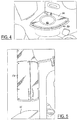
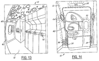
Figures 1-14 illustrate various perspective views of a cabin region of a commercial aircraft having translucent components formed according to the present invention; -
Figure 15 is a side view a two-layer composite material having weaved fibrous material used to form the translucent components ofFigures 1-14 ; -
Figure 16 a side view a three-layer composite material used to form the translucent components ofFigures 1-14 ; and -
Figure 17 a side view a two-layer composite material having unidirectional fibers used to form the translucent components ofFigures 1-14 . - The present invention describes the formation of composite materials that are ideally suited for use as translucent components for various devices contained within cabin areas of commercial aircraft due to their light transmissivity properties and flame retardancy. The composite materials could find usage in other aerospace applications.
-
Figures 1-14 illustrate various views of an interior, orcabin region 12, of acommercial aircraft 10. Theaircraft 10 has a wide variety of translucent components 14 that are traditionally found within thecabin region 12 that are formed from a novelcomposite material 70 that is the subject of the present invention. - The components 14 formed are light transmissive to allow for a pleasing glow or to allow for use as primary lighting within the
cabin region 12. - The materials also meet flammability standards. For example, the standard test method for heat release is the Ohio State University heat release test as found in FAR 25.853, Part IV, in which the maximum allowable average heat release for interior panels contained with the cabin area of commercial airlines does not exceed 65kw/m2 as measure at a two minute interval and for a peak rate at five minutes. This is also known in the industry as the 65/65 standard (peak heat release/total heat release).
- The translucent components 14 also meet Federal Aviation Association (FAA) certification requirements for materials used overhead in the
passenger cabin area 12. These certification requirements state that thecomposite material 70 must not drip or dislodge from their designated flight configuration such that they inhibit egress when exposed to a temperature of 500 degrees Fahrenheit (260 degrees Celsius) for five minutes. - Non-limiting examples of translucent components 14 that are formed from the
composite material 70 of the present invention include,countertops 16,cabinet enclosures 18 such as wastebaskets, tray tables 20, backlit lightedsigns 22 such asemergency exit signs 24,illuminating window panels 26 having light emitting diode displays 28,window bezels 30,class dividers 32,privacy partitions 34,backlit ceiling panels 36, directlighting ceiling panels 38, lighteddoors 40, lighteddoor latches 42, doorway linings 44,proximity lights 46, stow bin doors 48,privacy curtains 50, translucent door handles 52 (capable of changing from red to green, for example),translucent amenities cabinets 54,translucent sink decks 56 for lavatories and kitchens (with or without an appropriate undersink enclosure 58),doorway liners 60, stowbin latch handles 62,lighted phones 64, and backlit control panels 66. While these components 14 are illustrated in one preferred arrangement, it is understood that the number, type, and location of these translucent components 14 may vary greatly among various types ofcommercial aircraft 10 are not meant to be limited to the illustrated arrangement. -
Figures 15-17 illustrate three preferredcomposite materials 70 that can subsequently be post-processed to form the translucent components 14 ofFigures 1-14 .Figure 15 illustrates a two-layer composite material, whileFigure 16 illustrates a three-layer composite material. In addition,Figure 17 illustrates another preferred two-layer composite material utilizing a unidirectional fiberglass material. Each is described below. - Referring now to
Figure 15 , a two-layercomposite material 70 is formed by laminating a layer of weavedfibrous material 72 to asubstrate material 74. InFigure 16 , a three-layercomposite material 70 is formed by introducing second layer ofsubstrate material 76 having the same composition asfirst layer 74 such that thefibrous material 72 is sandwiched and laminated between first andsecond layer Figure 17 , a unidirectional, non-weavedfibrous material 72 is laminated to the substrate material to form another two-layer translucentcomposite material 70. - Of course, while three preferred embodiments are illustrated in
Figures 15-17 , other preferred embodiments are specifically contemplated. For instance, one three-layercomposite material 70 consists of a weavedfibrous material 72 sandwiched between and laminated to thefirst layer 74 andsecond layer 76 as inFigure 16 . Also, two layers of fibrous material 72 (weaved or unidirectional) could be introduced to a top and bottom surface of thesubstrate material 74 to form anothercomposite material 70. - The
substrate material 74 is chosen based on the application for which it is utilized. In the case of airplane interior components 14, thesubstrate material 74 is chosen to allow adequate light transmissivity for the desired component. Thesubstrate material 74 has the ability to soften to permit lamination of thefibrous material 72 as well as being able to be post processed to form a translucent component 14 having a desired shape and thickness. It is also desirable that thesubstrate material 74 is low cost, durable, and is available in varying thickness to provide design flexibility. Additionally, thesubstrate material 74 should be compatible with thefibrous material 72 and resist degradation due to light, heat, and stress. - One thermoplastic resin that meets these requirements is polyphenylsulfone, otherwise known as PPSU. PPSU is a translucent thermoplastic material typically that is relatively light transmissive and typically has a light brown tint. As one of ordinary skill appreciates, many grades of PPSU are commercially available, each having slightly varying transmissivity and flammability resistant properties. One preferred PPSU material is Radel PPSU, available from Solvay Advanced Polymers, LLC.
- The
fibrous material 72 is added to thePPSU substrate composite panel 60 in the event of fire. Thefibrous material 72 laminated within the substrate orsubstrates Long glass fibers 78 are preferred for use as thefibrous material substrate 70 to pass flammability tests, their ability to not overly decrease light transmissivity, and their overall appearance within thePPSU substrate - The
long glass fibers 78 utilized should have a thread count that is coarse enough to allow sufficient light transmission between thefibers 78 and through thesubstrate fibers 78 in thefibrous material visible fibers 78 in thecomposite material 70 should have a consistent appearance. Additionally, sufficient density offibers 78 should be present to ensure article retention. - Preferably, the
long glass fibers 78 have melting temperatures substantially above the melting temperature of thePPSU substrate 74. Preferably, the glass fibers are able to support thePPSU substrate 74 once thePPSU substrate 74 is softened at 260°C (500 degrees Fahrenheit.) Two types ofglass fibers 78 that meet these criteria are e-glass and s-glass fibers. - The
fiber 78 density, thickness, and orientation are all properties that may be optimized for a particular application. A higher density offibers 78, orthicker fibers 78, within thePPSU substrate 74 will provide additional strength and will act as a heat sink when exposed to fire while adversely affecting light transmissivity and overall weight. A particular fiber orientation, or fiber weave, may also affect weight, flammability, overhead fire retention, material strength, and light transmission. Thus, if more light transmission is desired, such as in an backlitlight sign 22 or emergency exit sign, the fiber density, thickness, and orientation will be set to allow maximum transmissivity while maintaining the 65/65 standard. With tray tables 20, the density of glass fiber, for example, may be increased compared to backlitlight signs 22, as transmissivity of light is not necessary. - The
composite material 70 may be formed by many different and unique methods. Two preferred methods for forming thecomposite material 70 are the thermal pressing process and the continuous fiber impregnation process. Each is described below with respect to the two-layer composite material 70 ofFigure 15 . However, as one of ordinary skill recognizes, the same preferred processes may be manipulated slightly to form the three-layer composite material 70 ofFigure 16 or the two-layer composite material 70 havingunidirectional fibers 78 as inFigure 17 . - In the thermal pressing process, the
substrate material 74 andfibrous material 72 are first introduced within a mold. The mold is first heated under controlled pressure to soften thesubstrate material 74. This is known as the preheating stage. Next, in the impregnation stage, higher heat and pressure are introduced to laminate thefibrous material 72 to thesubstrate material 74. The higher heat and pressure allows the impregnation of the embeddedglass fibers 78 and substantially encapsulates thefibers 78 with thePPSU substrate material 74, therein forming thecomposite material 70. Finally, in the cooling stage, the composite material is cooled under controlled heat and pressure conditions to control internal stresses and warpage. - In one preferred example of this process, a
composite sheet 60 of 0.254 cm (0.1 inches) in thickness is formed by first introducing thePPSU substrate material 74 andfibrous material 72 to a mold. Next, in the preheating stage, the mold is heated to 279.4°C ( 535 degrees Fahrenheit) over 15 minutes. - The mold is then held at 279.4°C ( 535 degrees) for 55 minutes at during the impregnation stage. During this time, the pressure is ratcheted upward slowly to prevent outgassing of the PPSU substrate material, therein preventing bubbles formed within the
composite sheet 70. Thus, between 0 and 5 minutes, the pressure is maintained at 103.4 kPa ( 15 pounds per square inch) part pressure. Between 5 and 27 minutes, the pressure is maintained at 344.7 kPa ( 50 pounds per square inch) part pressure. Between 27 and 47 minutes, the pressure is maintained at 689.5 kPa (100 pounds per square inch) part pressure. Finally, between 47 and 55 minutes, the pressure is maintained at 1379.0 kPa ( 200 pounds per square inch) part pressure. - Next, in the cooling stage, the composite part is allowed to slowly cool down to 112.8°C (235 degrees Fahrenheit ) under constant pressure of 1379.0 kPa (200 pounds per square) part pressure. The cooling rate is maintained at -15°C (5 degrees Fahrenheit ) per minute, thus this portion of the cooling stage lasts approximately one hour to control internal stresses and warpage of the forming composite part.
- Next, to further cool the composite part, the temperature within the mold is slowly decreased to 65.6°C( 150 degrees Fahrenheit ) and 689.5 kPa ( 100 pounds per square inch) part pressure to further control internal stresses and warpage. Finally, the mold is opened and the
composite sheet 70 is allowed to cool to room temperature. - The thermal pressing technique has many benefits over other techniques used for forming composite materials. First, the
fibers 78 are substantially encapsulated with the PPSU substrate material. Also, thermal pressing at a temperature below the melting point of the PPSU substrate allows sufficient flex without yield. Finally, the thermal pressing technique also allows the incorporation of decorative features into the composite material. For example, a screen print may be added to thefibers 78 prior to adding thefibers 78 to thePPSU substrate material 74. - In the continuous impregnation technique, molten PPSU resin making up the
substrate material 74 is introduced from an extruder having a die set between a pair of rollers contained within a calendar roll stack. At the same time, a sheet layer offibrous material 72 is unrolled from a roller onto the molten layer between the first set of rollers. The calendar roll stack, preferably containing three or more stainless steel calendar rolls stacked vertically, presses the fibrous material sheet layer and molten layer to a desired thickness, therein impregnating the PPSU resin within thefibrous material 72. Thecomposite material 70 formed then is removed from the calendar rolls stack on a conveyor belt line and allowed to cool, therein forming a cooled, hardenedcomposite sheet 70. - The continuous impregnation technique offers slightly different benefits to the thermal pressing technique. For example, because the process is continuous, the
composite sheet material 70 may be formed at a quicker rate than with the thermal pressing technique. This is also cost effective. Also, the thickness of the material formed may be easily modified by adjusting the clearance gap between the respective rollers of the calendar stack. Additionally, the process also automates impregnation techniques that would otherwise have to be accomplished manually. - After the
composite material 70 is formed by either of the preferred techniques described above or by any other techniques known to those of skill in the art, thecomposite material 70 is then available to be post-processed for the desired application. The type of post processing depends upon the component 14, and typically involves cutting, bending or thermoforming the part to a desired shape and size. - For example, a
privacy curtain 50 must remain flexible, and is thus formed as a very thin composite material. Conversely, acountertop 16 must be able to support items placed upon it, and thus is formed with a thickness much greater than theprivacy curtain 50. - Also, for example, the amount of light transmissivity may vary based upon the ultimate use of the component. Thus, an
emergency exit sign 24 may be formed of a thincomposite material 70 and with a lower fiber thread per unit area, therein allowing maximum light transmissivity. Conversely, a ceiling may be formed with minimal light transmissivity having higher fiber thread count per unit area, therein providing maximum flammability resistance. - The component 14 is then available for use within the
cabin area 12. To form the component, thecomposite material 70 having the desired light transmissivity and flame resistant characteristics as described above is bent, cut thermoformed or otherwise post-processed in methods well known in the art to shape and size the part to the desired configuration. - While the invention has been described in terms of preferred embodiments, it will be understood, of course, that the invention is not limited thereto since modifications may be made by those skilled in the art, particularly in light of the foregoing teachings.
Claims (19)
- A translucent, flame-resistant panel for use in the interior of an aircraft, the panel being formed of a two-layer composite material comprising:a polyphenylsulfone substrate material; anda plurality of long glass fibers substantially embedded within said polyphenylsulfone substrate material such that the composite material has an average allowable heat release not exceeding a 65/65 standard, according to the Ohio State University heat release test as found in FAR 25.853 Part IV,wherein said plurality of long glass fibers is selected from a plurality of long s-type glass fibers and a plurality of long e-type glass fibers.
- The translucent, flame-resistant panel of claim 1, wherein said plurality of long glass fibers comprises a plurality of unidirectional long glass fibers.
- The translucent, flame-resistant panel of claim 1, wherein said panel is selected from a countertop, a cabinet enclosure, a tray table, a backlit lighted sign, an illuminating window panel, a window bezel, a class divider, a privacy partition, a backlit ceiling panel, a direct lighting ceiling panel, a backlit control panel, a lighted door, a lighted door latch, a doorway lining, a proximity light, a stow bin door, a privacy curtain, a translucent door handle, a translucent amenities cabinet, a translucent sink deck, a doorway liner, a stow bin latch handle, and a lighted phone.
- The translucent, flame-resistant panel of claim 1 wherein the composite material comprises:a first layer of said polyphenylsulfone substrate material;a second layer of said polyphenylsulfone substrate material; andwherein said plurality of long glass fibers is sandwiched between and substantially embedded within said first layer and said second layer, wherein said layers form a three-layer composite material.
- The translucent, flame-resistant panel of claim 4, wherein said plurality of long glass fibers comprises a plurality of unidirectional long glass fibers.
- The translucent, flame-resistant panel of claim 4, wherein said panel is selected from a countertop, a cabinet enclosure, a tray table, a backlit lighted sign, an illuminating window panel, a window bezel, a class divider, a privacy partition, a backlit ceiling panel, a direct lighting ceiling panel, a backlit control panel, a lighted door, a lighted door latch, a doorway lining, a proximity light, a stow bin door, a privacy curtain, a translucent door handle, a translucent amenities cabinet, a translucent sink deck, a doorway liner, a stow bin latch handle, and a lighted phone.
- The translucent, flame-resistant panel of claim 1, wherein the composite material comprises:a first layer of a plurality of said long glass fibers;a second layer of a plurality of said long glass fibers; anda layer of said thermoplastic polyphenylsulfone substrate material sandwiched between and embedding said first layer and said second layer, wherein said layers form a three-layer composite material.
- A method for forming a translucent, flame-resistant panel formed of a composite material, the method comprising:introducing a layer of thermoplastic polyphenylsulfone substrate material to a mold;introducing a fibrous material onto an entire top surface of said polyphenylsulfone substrate material within said mold, said fibrous material comprising a plurality of long glass fibers, wherein said plurality of long glass fibers is selected from a plurality of long e-type glass fibers and a plurality of long s-type glass fibers, and wherein said plurality of long glass fibers has a melting temperature above the melting temperature of said polyphenylsulfone;preheating said mold to a first temperature to soften said polyphenylsulfone substrate material;laminating said fibrous material to said polyphenylsulfone substrate material such that said plurality of long glass fibers are substantially encapsulated within said polyphenylsulfone substrate material while substantially preventing said polyphenylsulfone substrate from outgassing;cooling said mold under controlled heat and pressure to form the composite material;removing said composite material from said mold; andpost processing said composite material to form a translucent, flame resistant panel.
- The method of claim 8, wherein introducing a fibrous material comprises introducing a plurality of unidirectional long glass fibers onto an entire top surface of said polyphenylsulfone substrate material within said mold.
- The method of claim 8, wherein preheating said mold comprises preheating said mold to 279.4°C (535 degrees Fahrenheit) over 15 minutes to soften said polyphenylsulfone substrate material.
- The method of claim 10, wherein laminating said fibrous material to said polyphenylsulfone substrate material comprises:holding said mold at 279.4°C (535 degrees Fahrenheit) for 0 minutes to 55 minutes;increasing said pressure of said mold at 0 minutes to 103.4kPa (103.4kPa (15 pounds per square inch)) part pressure;holding said mold at 103.4kPa (15 pounds per square inch) part pressure between about 0 minutes and 5 minutes;increasing said pressure from 103.4kPa (15 pounds per square inch) part pressure to 344.7kPa (50 pounds per square inch) part pressure at 5 minutes;holding said mold at 344.7kPa (50 pounds per square inch) part pressure between about 5 minutes and 27 minutes;increasing said pressure from 344.7kPa (50 pounds per square inch) part pressure to 689.5kPa (100 pounds per square inch) part pressure at 27 minutes;holding said mold at 689.5kPa (100 pounds per square inch) part pressure between 27 minutes and 47 minutes;increasing said pressure from 689.5kPa (100 pounds per square inch) part pressure to 1379.0kPa (200 pounds per square inch) part pressure at 47 minutes; andholding said mold at 1379.0kPa (200 pounds per square inch) part pressure between 47 minutes and 55 minutes.
- The method of claim 10, wherein cooling said mold comprises: slowly cooling said mold from 279.4°C (535 degrees Fahrenhet) to 112.8°C (235 degrees Fahrenheit) at 1379.0kPa (200 pounds per square inch) part pressure at a cooling rate of 15°C (5 degrees Fahrenheit) per minute; and further cooling said mold to 65.6°C (150 degrees Fahrenheit) at 689.5kPa (100 pounds per square inch) part pressure.
- The method of claim 8, wherein said method comprises:introducing a first layer of said thermoplastic polyphenylsulfone substrate material to said mold;introducing said fibrous material onto an entire top surface of said polyphenylsulfone substrate material within said mold;introducing a second layer of said thermoplastic polyphenylsulfone substrate material to said mold such that said fibrous material is sandwiched between said first layer and said second layer;preheating said mold to said first temperature to soften said first layer and said second layer;laminating said fibrous material to said first layer and said second layer such that said plurality of long glass fibers are substantially encapsulated within said polyphenylsulfone substrate material while substantially preventing said first layer and said second layer from outgassing.
- The method of claim 13, wherein introducing a fibrous material comprises introducing a plurality of unidirectional long glass fibers onto an entire top surface of said polyphenylsulfone substrate material within said mold.
- The method of claim 13, wherein preheating said mold comprises preheating said mold to 279.4°C (535 degrees Fahrenheit) over 15 minutes to soften said polyphenylsulfone substrate material.
- The method of claim 15, wherein laminating said fibrous material to said polyphenylsulfone substrate material comprises:holding said mold at 279.4°C (535 degrees Fahrenheit) for 0 minutes to 55 minutes;increasing said pressure of said mold at 0 minutes to 103.4kPa (15 pounds per square inch) part pressure;holding said mold at 103.4kPa (15 pounds per square inch) part pressure between about 0 minutes and 5 minutes;increasing said pressure from 103.4kPa (15 pounds per square inch) part pressure to 344.7kPa (50 pounds per square inch) part pressure at 5 minutes;holding said mold at 344.7kPa (50 pounds per square inch) part pressure between about 5 minutes and 27 minutes;increasing said pressure from 344.7kPa (50 pounds per square inch) part pressure to 689.5kPa (100 pounds per square inch) part pressure at 27 minutes;holding said mold at 689.5kPa (100 pounds per square inch) part pressure between 27 minutes and 47 minutes;increasing said pressure from 689.5kPa (100 pounds per square inch) part pressure to 1379.0kPa (200 pounds per square inch) part pressure at 47 minutes; andholding said mold at 1379.0kPa (200 pounds per square inch) part pressure between 47 minutes and 55 minutes.
- The method of claim 16, wherein cooling said mold comprises:slowly cooling said mold from 279.4°C (535 degrees Fahrenheit) to 112.8°C (235 degrees Fahrenheit) at 1379.0kPa (200pounds per square inch) part pressure at a cooling rate of 15°C (5 degrees Fahrenheit) per minute; andfurther cooling said mold to 65.6°C (150 degrees Fahrenheit) at 689.5kPa (100 pounds per square inch) part pressure.
- The method of claim 8, wherein post processing said composite material is selected from cutting said composite material to a desired shape and size, thermoforming said composite material to a desired shape and size and bonding said composite material to a desired shape and size.
- The method of claim 8, wherein said translucent, flame-resistant panel is selected from a countertop, a cabinet enclosure, a tray table, a backlit lighted sign, an illuminating window panel, a window bezel, a class divider, a privacy partition, a backlit ceiling panel, a direct lighting ceiling panel, a backlit control panel, a lighted door, a lighted door latch, a doorway lining, a proximity light, a stow bin door, a privacy curtain, a translucent door handle, a translucent amenities cabinet, a translucent sink deck a doorway liner, a stow bin latch handle, and a lighted phone.
Applications Claiming Priority (2)
| Application Number | Priority Date | Filing Date | Title |
|---|---|---|---|
| US10/707,612 US20050142968A1 (en) | 2003-12-24 | 2003-12-24 | Translucent, flame resistant composite materials |
| PCT/US2004/038242 WO2005065944A1 (en) | 2003-12-24 | 2004-11-10 | Translucent, flame resistant composite material |
Publications (2)
| Publication Number | Publication Date |
|---|---|
| EP1704050A1 EP1704050A1 (en) | 2006-09-27 |
| EP1704050B1 true EP1704050B1 (en) | 2016-05-25 |
Family
ID=34700309
Family Applications (1)
| Application Number | Title | Priority Date | Filing Date |
|---|---|---|---|
| EP04817829.7A Expired - Lifetime EP1704050B1 (en) | 2003-12-24 | 2004-11-10 | Translucent, flame resistant composite materials |
Country Status (3)
| Country | Link |
|---|---|
| US (2) | US20050142968A1 (en) |
| EP (1) | EP1704050B1 (en) |
| WO (1) | WO2005065944A1 (en) |
Families Citing this family (8)
| Publication number | Priority date | Publication date | Assignee | Title |
|---|---|---|---|---|
| DE102007001578B4 (en) * | 2007-01-10 | 2018-10-11 | Diehl Aviation Laupheim Gmbh | Backlit aircraft interior component |
| US8277070B1 (en) | 2009-11-17 | 2012-10-02 | Crafted Countertops, Inc. | Counter with border lighting |
| FR2960902B1 (en) * | 2010-06-08 | 2015-04-24 | Baumert Technologies | FIRE-CUTTING DOOR BLOCK HAS ONE OR TWO PIVOTING DOORS (S) |
| JP6535167B2 (en) * | 2015-01-21 | 2019-06-26 | 三菱航空機株式会社 | Aircraft and fuselage cooling structure |
| US10125439B2 (en) | 2017-02-02 | 2018-11-13 | Douglas J. Bailey | Flexible translucent to transparent fireproof composite material |
| DE102017215369A1 (en) * | 2017-09-01 | 2019-03-07 | Benecke-Kaliko Ag | Translucent multi-layer composite film |
| GB2569151B (en) * | 2017-12-07 | 2021-01-27 | Jaguar Land Rover Ltd | Reformable article |
| US12491981B2 (en) | 2023-03-08 | 2025-12-09 | Jetzero, Inc. | Blended wing body aircraft with transmissive panels |
Family Cites Families (14)
| Publication number | Priority date | Publication date | Assignee | Title |
|---|---|---|---|---|
| US3434914A (en) * | 1966-02-01 | 1969-03-25 | Union Carbide Corp | Glass fiber reinforced thermoplastic polyarylene polyether resin article and process for making same |
| FR2619399B1 (en) * | 1987-08-11 | 1991-10-25 | Brochier Sa | TEXTILE STRUCTURE FOR THE PRODUCTION OF LAMINATES WITH HIGH MECHANICAL PROPERTIES |
| EP0312151B1 (en) * | 1987-10-14 | 1991-03-27 | Akzo N.V. | Laminate of metal sheets and continuous glass filaments-reinforced synthetic material |
| DE3741539A1 (en) * | 1987-12-08 | 1989-06-22 | Bayer Ag | LIGHT COMPOSITE MATERIAL, COMPOSITE MATERIAL WHICH CAN TRANSFER IN THIS LIGHT COMPOSITE MATERIAL, METHOD FOR THE PRODUCTION OF THE LIGHT COMPOSITE MATERIAL AND COMPOSITE MATERIAL AND PARTS CONTAINING OR EXISTING FROM THE LIGHT COMPOSITE MATERIAL |
| GB8925193D0 (en) * | 1989-11-08 | 1991-01-02 | Royal Ordnance Plc | The protection of aircraft structures |
| US5258445A (en) * | 1990-03-08 | 1993-11-02 | The B. F. Goodrich Company | Fiber-reinforced thermoplastic molding compositions using a copolyester |
| JPH0817880B2 (en) * | 1990-11-28 | 1996-02-28 | 帝人株式会社 | Press cushion material |
| US5319003A (en) * | 1992-09-30 | 1994-06-07 | Union Carbide Chemicals & Plastics Technology Corporation | Method for improving the mechanical performance of composite articles |
| US5398889A (en) * | 1994-02-22 | 1995-03-21 | Furon Company | Aircraft fuselage lining system |
| JPH08193623A (en) * | 1994-10-25 | 1996-07-30 | Koyo Seiko Co Ltd | Retainer for rolling bearing |
| US5911932A (en) * | 1997-07-09 | 1999-06-15 | R. Charles Balmer | Method of prepregging with resin |
| US6242638B1 (en) * | 1999-03-12 | 2001-06-05 | Vantico Inc. | Cyanate esters having flame resistant properties |
| US6673872B2 (en) * | 2000-05-17 | 2004-01-06 | General Electric Company | High performance thermoplastic compositions with improved melt flow properties |
| US20040219855A1 (en) * | 2003-05-02 | 2004-11-04 | Tsotsis Thomas K. | Highly porous interlayers to toughen liquid-molded fabric-based composites |
-
2003
- 2003-12-24 US US10/707,612 patent/US20050142968A1/en not_active Abandoned
-
2004
- 2004-11-10 EP EP04817829.7A patent/EP1704050B1/en not_active Expired - Lifetime
- 2004-11-10 WO PCT/US2004/038242 patent/WO2005065944A1/en not_active Ceased
-
2009
- 2009-10-12 US US12/577,618 patent/US8007620B2/en not_active Expired - Fee Related
Also Published As
| Publication number | Publication date |
|---|---|
| US20100059900A1 (en) | 2010-03-11 |
| WO2005065944A1 (en) | 2005-07-21 |
| US8007620B2 (en) | 2011-08-30 |
| US20050142968A1 (en) | 2005-06-30 |
| EP1704050A1 (en) | 2006-09-27 |
Similar Documents
| Publication | Publication Date | Title |
|---|---|---|
| US8007620B2 (en) | Translucent, flame resistant composite materials | |
| US10180517B2 (en) | Vehicle mirror, and method for manufacturing such a mirror | |
| US7682697B2 (en) | Fiber reinforced thermoplastic sheets with surface coverings | |
| US20050272329A1 (en) | Wire mesh panel and method | |
| US20160136929A1 (en) | Composite Element and Use Thereof | |
| US20150284910A1 (en) | Fiber reinforced thermoplastic sheets with surface coverings | |
| US9650496B2 (en) | Interior aircraft components and methods of manufacture | |
| JP2000343632A (en) | Composite structure produced by using structural panel having core equipped with thermoplastic resin exterior material and decorative film bonded thereto | |
| USRE44893E1 (en) | Fiber reinforced thermoplastic sheets with surface coverings | |
| US8617715B2 (en) | Fire retardant shades | |
| EP0529980A1 (en) | Thermoformable polycarbonate/woven glass cloth composites | |
| EP1874537B1 (en) | Layered, transparent thermoplastic for flammability resistance | |
| MXPA04002337A (en) | Composite foam products and method. | |
| CN113022033A (en) | Ballistic panel and method of making a ballistic panel | |
| KR20190052691A (en) | Laminated decorative film, method of manufacturing the same, and decorative molded article and manufacturing method thereof | |
| US20120156440A1 (en) | Translucent, Flame Resistant Composite Materials | |
| CN116472255A (en) | Reinforced glass ceramic products | |
| Lyon | Materials with reduced flammability in aerospace and aviation | |
| CN108474156A (en) | Flame-retardant polycarbonate composites for semi-structural panels | |
| EP4009017B1 (en) | Systems and methods of use of uv-responsive laminates and methods of fabrication thereof | |
| JP3187473U (en) | Decorative panel | |
| CN112549707A (en) | Food-grade flame-retardant aviation plate and manufacturing method thereof | |
| JP2015116805A (en) | Polycarbonate laminate and roofing material | |
| US20200296864A1 (en) | Antenna screening composite, panel, assembly, and method of manufacturing same | |
| KR100896476B1 (en) | Decorative sheet excellent in interlayer adhesion and its manufacturing method |
Legal Events
| Date | Code | Title | Description |
|---|---|---|---|
| PUAI | Public reference made under article 153(3) epc to a published international application that has entered the european phase |
Free format text: ORIGINAL CODE: 0009012 |
|
| 17P | Request for examination filed |
Effective date: 20060706 |
|
| AK | Designated contracting states |
Kind code of ref document: A1 Designated state(s): AT BE BG CH CY CZ DE DK EE ES FI FR GB GR HU IE IS IT LI LU MC NL PL PT RO SE SI SK TR |
|
| 17Q | First examination report despatched |
Effective date: 20061026 |
|
| DAX | Request for extension of the european patent (deleted) | ||
| GRAP | Despatch of communication of intention to grant a patent |
Free format text: ORIGINAL CODE: EPIDOSNIGR1 |
|
| INTG | Intention to grant announced |
Effective date: 20151208 |
|
| GRAS | Grant fee paid |
Free format text: ORIGINAL CODE: EPIDOSNIGR3 |
|
| GRAA | (expected) grant |
Free format text: ORIGINAL CODE: 0009210 |
|
| AK | Designated contracting states |
Kind code of ref document: B1 Designated state(s): AT BE BG CH CY CZ DE DK EE ES FI FR GB GR HU IE IS IT LI LU MC NL PL PT RO SE SI SK TR |
|
| REG | Reference to a national code |
Ref country code: GB Ref legal event code: FG4D |
|
| REG | Reference to a national code |
Ref country code: CH Ref legal event code: EP |
|
| REG | Reference to a national code |
Ref country code: IE Ref legal event code: FG4D Ref country code: AT Ref legal event code: REF Ref document number: 801926 Country of ref document: AT Kind code of ref document: T Effective date: 20160615 |
|
| REG | Reference to a national code |
Ref country code: DE Ref legal event code: R096 Ref document number: 602004049377 Country of ref document: DE |
|
| REG | Reference to a national code |
Ref country code: NL Ref legal event code: MP Effective date: 20160525 |
|
| PG25 | Lapsed in a contracting state [announced via postgrant information from national office to epo] |
Ref country code: FI Free format text: LAPSE BECAUSE OF FAILURE TO SUBMIT A TRANSLATION OF THE DESCRIPTION OR TO PAY THE FEE WITHIN THE PRESCRIBED TIME-LIMIT Effective date: 20160525 Ref country code: NL Free format text: LAPSE BECAUSE OF FAILURE TO SUBMIT A TRANSLATION OF THE DESCRIPTION OR TO PAY THE FEE WITHIN THE PRESCRIBED TIME-LIMIT Effective date: 20160525 |
|
| REG | Reference to a national code |
Ref country code: AT Ref legal event code: MK05 Ref document number: 801926 Country of ref document: AT Kind code of ref document: T Effective date: 20160525 |
|
| REG | Reference to a national code |
Ref country code: FR Ref legal event code: PLFP Year of fee payment: 13 |
|
| PG25 | Lapsed in a contracting state [announced via postgrant information from national office to epo] |
Ref country code: GR Free format text: LAPSE BECAUSE OF FAILURE TO SUBMIT A TRANSLATION OF THE DESCRIPTION OR TO PAY THE FEE WITHIN THE PRESCRIBED TIME-LIMIT Effective date: 20160826 Ref country code: PT Free format text: LAPSE BECAUSE OF FAILURE TO SUBMIT A TRANSLATION OF THE DESCRIPTION OR TO PAY THE FEE WITHIN THE PRESCRIBED TIME-LIMIT Effective date: 20160926 Ref country code: SE Free format text: LAPSE BECAUSE OF FAILURE TO SUBMIT A TRANSLATION OF THE DESCRIPTION OR TO PAY THE FEE WITHIN THE PRESCRIBED TIME-LIMIT Effective date: 20160525 Ref country code: ES Free format text: LAPSE BECAUSE OF FAILURE TO SUBMIT A TRANSLATION OF THE DESCRIPTION OR TO PAY THE FEE WITHIN THE PRESCRIBED TIME-LIMIT Effective date: 20160525 |
|
| PG25 | Lapsed in a contracting state [announced via postgrant information from national office to epo] |
Ref country code: IT Free format text: LAPSE BECAUSE OF FAILURE TO SUBMIT A TRANSLATION OF THE DESCRIPTION OR TO PAY THE FEE WITHIN THE PRESCRIBED TIME-LIMIT Effective date: 20160525 |
|
| PG25 | Lapsed in a contracting state [announced via postgrant information from national office to epo] |
Ref country code: DK Free format text: LAPSE BECAUSE OF FAILURE TO SUBMIT A TRANSLATION OF THE DESCRIPTION OR TO PAY THE FEE WITHIN THE PRESCRIBED TIME-LIMIT Effective date: 20160525 Ref country code: CZ Free format text: LAPSE BECAUSE OF FAILURE TO SUBMIT A TRANSLATION OF THE DESCRIPTION OR TO PAY THE FEE WITHIN THE PRESCRIBED TIME-LIMIT Effective date: 20160525 Ref country code: RO Free format text: LAPSE BECAUSE OF FAILURE TO SUBMIT A TRANSLATION OF THE DESCRIPTION OR TO PAY THE FEE WITHIN THE PRESCRIBED TIME-LIMIT Effective date: 20160525 Ref country code: EE Free format text: LAPSE BECAUSE OF FAILURE TO SUBMIT A TRANSLATION OF THE DESCRIPTION OR TO PAY THE FEE WITHIN THE PRESCRIBED TIME-LIMIT Effective date: 20160525 Ref country code: SK Free format text: LAPSE BECAUSE OF FAILURE TO SUBMIT A TRANSLATION OF THE DESCRIPTION OR TO PAY THE FEE WITHIN THE PRESCRIBED TIME-LIMIT Effective date: 20160525 |
|
| PG25 | Lapsed in a contracting state [announced via postgrant information from national office to epo] |
Ref country code: BE Free format text: LAPSE BECAUSE OF FAILURE TO SUBMIT A TRANSLATION OF THE DESCRIPTION OR TO PAY THE FEE WITHIN THE PRESCRIBED TIME-LIMIT Effective date: 20160525 Ref country code: PL Free format text: LAPSE BECAUSE OF FAILURE TO SUBMIT A TRANSLATION OF THE DESCRIPTION OR TO PAY THE FEE WITHIN THE PRESCRIBED TIME-LIMIT Effective date: 20160525 Ref country code: AT Free format text: LAPSE BECAUSE OF FAILURE TO SUBMIT A TRANSLATION OF THE DESCRIPTION OR TO PAY THE FEE WITHIN THE PRESCRIBED TIME-LIMIT Effective date: 20160525 |
|
| REG | Reference to a national code |
Ref country code: DE Ref legal event code: R097 Ref document number: 602004049377 Country of ref document: DE |
|
| PLBE | No opposition filed within time limit |
Free format text: ORIGINAL CODE: 0009261 |
|
| STAA | Information on the status of an ep patent application or granted ep patent |
Free format text: STATUS: NO OPPOSITION FILED WITHIN TIME LIMIT |
|
| 26N | No opposition filed |
Effective date: 20170228 |
|
| PG25 | Lapsed in a contracting state [announced via postgrant information from national office to epo] |
Ref country code: SI Free format text: LAPSE BECAUSE OF FAILURE TO SUBMIT A TRANSLATION OF THE DESCRIPTION OR TO PAY THE FEE WITHIN THE PRESCRIBED TIME-LIMIT Effective date: 20160525 |
|
| REG | Reference to a national code |
Ref country code: CH Ref legal event code: PL |
|
| PG25 | Lapsed in a contracting state [announced via postgrant information from national office to epo] |
Ref country code: CH Free format text: LAPSE BECAUSE OF NON-PAYMENT OF DUE FEES Effective date: 20161130 Ref country code: LI Free format text: LAPSE BECAUSE OF NON-PAYMENT OF DUE FEES Effective date: 20161130 |
|
| REG | Reference to a national code |
Ref country code: IE Ref legal event code: MM4A |
|
| PG25 | Lapsed in a contracting state [announced via postgrant information from national office to epo] |
Ref country code: LU Free format text: LAPSE BECAUSE OF NON-PAYMENT OF DUE FEES Effective date: 20161130 |
|
| REG | Reference to a national code |
Ref country code: FR Ref legal event code: PLFP Year of fee payment: 14 |
|
| PG25 | Lapsed in a contracting state [announced via postgrant information from national office to epo] |
Ref country code: IE Free format text: LAPSE BECAUSE OF NON-PAYMENT OF DUE FEES Effective date: 20161110 |
|
| PG25 | Lapsed in a contracting state [announced via postgrant information from national office to epo] |
Ref country code: CY Free format text: LAPSE BECAUSE OF FAILURE TO SUBMIT A TRANSLATION OF THE DESCRIPTION OR TO PAY THE FEE WITHIN THE PRESCRIBED TIME-LIMIT Effective date: 20160525 Ref country code: HU Free format text: LAPSE BECAUSE OF FAILURE TO SUBMIT A TRANSLATION OF THE DESCRIPTION OR TO PAY THE FEE WITHIN THE PRESCRIBED TIME-LIMIT; INVALID AB INITIO Effective date: 20041110 |
|
| PG25 | Lapsed in a contracting state [announced via postgrant information from national office to epo] |
Ref country code: TR Free format text: LAPSE BECAUSE OF FAILURE TO SUBMIT A TRANSLATION OF THE DESCRIPTION OR TO PAY THE FEE WITHIN THE PRESCRIBED TIME-LIMIT Effective date: 20160525 Ref country code: MC Free format text: LAPSE BECAUSE OF FAILURE TO SUBMIT A TRANSLATION OF THE DESCRIPTION OR TO PAY THE FEE WITHIN THE PRESCRIBED TIME-LIMIT Effective date: 20160525 Ref country code: IS Free format text: LAPSE BECAUSE OF FAILURE TO SUBMIT A TRANSLATION OF THE DESCRIPTION OR TO PAY THE FEE WITHIN THE PRESCRIBED TIME-LIMIT Effective date: 20160525 |
|
| PG25 | Lapsed in a contracting state [announced via postgrant information from national office to epo] |
Ref country code: BG Free format text: LAPSE BECAUSE OF FAILURE TO SUBMIT A TRANSLATION OF THE DESCRIPTION OR TO PAY THE FEE WITHIN THE PRESCRIBED TIME-LIMIT Effective date: 20160525 |
|
| REG | Reference to a national code |
Ref country code: DE Ref legal event code: R082 Ref document number: 602004049377 Country of ref document: DE Representative=s name: MAIER, LL.M., MICHAEL C., DE Ref country code: DE Ref legal event code: R082 Ref document number: 602004049377 Country of ref document: DE Representative=s name: BOULT WADE TENNANT LLP, DE |
|
| REG | Reference to a national code |
Ref country code: DE Ref legal event code: R082 Ref document number: 602004049377 Country of ref document: DE Representative=s name: BOULT WADE TENNANT LLP, DE |
|
| PGFP | Annual fee paid to national office [announced via postgrant information from national office to epo] |
Ref country code: FR Payment date: 20211124 Year of fee payment: 18 Ref country code: GB Payment date: 20211129 Year of fee payment: 18 Ref country code: DE Payment date: 20211126 Year of fee payment: 18 |
|
| REG | Reference to a national code |
Ref country code: DE Ref legal event code: R119 Ref document number: 602004049377 Country of ref document: DE |
|
| GBPC | Gb: european patent ceased through non-payment of renewal fee |
Effective date: 20221110 |
|
| PG25 | Lapsed in a contracting state [announced via postgrant information from national office to epo] |
Ref country code: GB Free format text: LAPSE BECAUSE OF NON-PAYMENT OF DUE FEES Effective date: 20221110 Ref country code: DE Free format text: LAPSE BECAUSE OF NON-PAYMENT OF DUE FEES Effective date: 20230601 |
|
| PG25 | Lapsed in a contracting state [announced via postgrant information from national office to epo] |
Ref country code: FR Free format text: LAPSE BECAUSE OF NON-PAYMENT OF DUE FEES Effective date: 20221130 |