EP1703812B1 - Centring drum for filter assembly machines - Google Patents
Centring drum for filter assembly machines Download PDFInfo
- Publication number
- EP1703812B1 EP1703812B1 EP04816329A EP04816329A EP1703812B1 EP 1703812 B1 EP1703812 B1 EP 1703812B1 EP 04816329 A EP04816329 A EP 04816329A EP 04816329 A EP04816329 A EP 04816329A EP 1703812 B1 EP1703812 B1 EP 1703812B1
- Authority
- EP
- European Patent Office
- Prior art keywords
- relative
- longitudinal axis
- drum
- reference plane
- seat
- Prior art date
- Legal status (The legal status is an assumption and is not a legal conclusion. Google has not performed a legal analysis and makes no representation as to the accuracy of the status listed.)
- Expired - Lifetime
Links
- 235000019504 cigarettes Nutrition 0.000 claims description 8
- 230000008878 coupling Effects 0.000 claims description 5
- 238000010168 coupling process Methods 0.000 claims description 5
- 238000005859 coupling reaction Methods 0.000 claims description 5
- 241000208125 Nicotiana Species 0.000 description 1
- 235000002637 Nicotiana tabacum Nutrition 0.000 description 1
- 230000002093 peripheral effect Effects 0.000 description 1
- 230000002035 prolonged effect Effects 0.000 description 1
- 230000000284 resting effect Effects 0.000 description 1
Images

Classifications
-
- A—HUMAN NECESSITIES
- A24—TOBACCO; CIGARS; CIGARETTES; SIMULATED SMOKING DEVICES; SMOKERS' REQUISITES
- A24C—MACHINES FOR MAKING CIGARS OR CIGARETTES
- A24C5/00—Making cigarettes; Making tipping materials for, or attaching filters or mouthpieces to, cigars or cigarettes
- A24C5/47—Attaching filters or mouthpieces to cigars or cigarettes, e.g. inserting filters into cigarettes or their mouthpieces
- A24C5/478—Transport means for filter- or cigarette-rods in view of their assembling
Definitions
- the present invention relates to a centring drum for filter assembly machines.
- filter portions of a length equal to that of an even number of filters, normally four or six, are fed into a hopper, from which they are withdrawn by an extracting drum having a number of peripheral seats equally spaced about the extracting drum and for receiving and retaining respective filter portions by suction.
- Each of the filter portions is fed by the extracting drum through a cutting station where it is cut into a number of shorter filter portions defining respective double filters, i.e. twice the length of a cigarette filter, positioned coaxially inside the respective seat.
- the double filters in each number are then transferred to an offsetting drum, which offsets them angularly with respect to one another to form, along its periphery, a number of rows of double filters equal to the number of double filters formed from each filter portion.
- the double filters in each row are equally spaced with a first spacing, which is equal for all the rows, about the axis of the offsetting drum, and each double filter in each row is offset, with respect to a corresponding double filter in an adjacent row, by a second spacing equal to a submultiple of the first spacing.
- the offset double filters are then fed to a centring drum, which shuffles the rows, by shifting them laterally, into a single row in which the double filters are spaced with said second spacing.
- This single row is then fed in known manner to a feed line supplying cigarette portions, to form double cigarettes.
- the rows are normally shuffled by means of fixed external converging plates, which gradually engage the rows of double filters, and slide the double filters axially along the relative seats into alignment with one another and into a central position normally centred with respect to a reference plane crosswise to the rotation axis of the centring drum.
- centring drums of the type described above have drawbacks when making any change in format, which normally involves changing and/or dismantling and reassembling said plates, thus resulting in relatively prolonged downtime.
- WO03043449A1 discloses a filter placement machine comprising a main drum and a number of additional assigned drums; the elements of the filter cigarettes, namely the tobacco stock or partial stocks, filter pieces, cigarette units, and the filter cigarettes manufactured from these elements are conveyed through the main drum with the exception that partial stocks with an inserted filter piece that are displaced at a distance from one another are conveyed out of the main drum in order to apply a covering paper and are joined to one another whereupon these now one-piece cigarette units are fed back to the main drum.
- centring drum as recited in the attached Claims.
- Number 1 in the accompanying drawings indicates as a whole a substantially cylindrical centring drum mounted for rotation about a respective longitudinal axis 2, and which provides for receiving two side by side rows 3 and 4 of double filters 5 - which rows are located on opposite sides of a substantially central reference plane T crosswise to longitudinal axis 2, and are offset angularly about axis 2 - and for shuffling the two rows 3 and 4 through reference plane T to form a single row 6 centred with respect to reference plane T and comprising a succession of double filters 5 positioned parallel to axis 2 and spaced about axis 2 with a spacing equal to half the spacing of double filters 5 in rows 3 and 4.
- centring drum 1 comprises a substantially cylindrical shell 7 coaxial with longitudinal axis 2, rotating about longitudinal axis 2, and through which reference plane T extends.
- shell 7 comprises a cylindrical surface 8, a central portion of which is fitted with a larger-diameter sleeve 9 centred with respect to reference plane T, bounded axially by two annular shoulders 10, and bounded externally by a cylindrical surface 11 coaxial with longitudinal axis 2 and having a number of substantially semicylindrical-section grooves 12, each defining a seat for a relative double filter 5.
- grooves 12 are parallel to longitudinal axis 2, are equally spaced about longitudinal axis 2, extend through reference plane T, and each receive a respective double filter 5 originally located entirely on one side of reference plane T. That is, if two adjacent grooves 12 are considered in the example shown, the relative double filters 5 are originally located on opposite sides of reference plane T.
- shell 7 is open at the rear, comprises a cylindrical inner surface 13 coaxial with longitudinal axis 2, and is bounded at the front by an end wall 14 having an inner surface 15, through which is formed a cylindrical cavity 16 coaxial with longitudinal axis 2 and in turn comprising an end surface 17 having a through hole 18.
- Hole 18 is coaxial with longitudinal axis 2, and connects cavity 16 to a cavity 19 formed in an outer surface 20 of end wall 14.
- a rear portion of inner surface 13 is fitted inside in fluidtight manner with the end of a drive shaft 21 having an axial end appendix 22, the free end of which is fitted with a cylindrical head 23 resting against end surface 17 of cavity 16 and having a cylindrical centring appendix 24 shorter in length than hole 18, and the outer surface of which mates with the inner surface of hole 18.
- Drive shaft 21 is connected angularly to shell 7 by means of a cylindrical plate 25 located frontwards of end wall 14, and which is housed partly inside cavity 19, is fixed angularly with respect to drive shaft 21 by means of a pin 26, and is connected to head 23 by axial screws 27 which grip end wall 14 between head 23 and plate 25.
- the shell is associated with a centring device 28 comprising a suction circuit 29, a stop device 30, and an adjusting device 31 for adjusting stop device 30.
- Suction circuit 29 comprises a known suction pump (not shown), the inlet of which is connected to a dead conduit 32 formed along drive shaft 21 and axial appendix 22, coaxially with longitudinal axis 2; a chamber 33 defined, inside shell 7 and about axial appendix 22, between the end of drive shaft 21 and end wall 14, and connected to conduit 32 by radial holes 34; and two rings 35 and 36 of radial holes 37 formed through shell 7 and sleeve 9, and each communicating with a respective groove 12.
- the two rings 35 and 36 are located on opposite sides of reference plane T, and at a distance from reference plane T greater than the length of the longest double filter 5 that can be accommodated on centring drum 1; and holes 37 in each ring 35, 36 are spaced about longitudinal axis 2 with a spacing equal to twice the spacing of grooves 12, and are offset, with respect to holes 37 in the other ring 36, 35 and about longitudinal axis 2, by a spacing equal to the spacing of grooves 12. Consequently, if one groove 12 communicates with a hole 37 in ring 35, the two adjacent grooves 12 communicate with respective holes 37 in ring 36.
- Stop device 30 comprises two rings 38 and 39, which are fitted idly to the portions of shell 7 projecting outwards of sleeve 9, with ring 38 interposed between reference plane T and plate 25 and located on the opposite side of ring 35 to reference plane T, and have respective axial fingers 40, each of which extends from relative ring 38, 39 towards the other ring 39, 38, engages in axially sliding manner a respective groove 12, at the end of groove 12 having relative hole 37, and is less than half the length of groove 12, but long enough to cover relative hole 37 in any operating condition.
- fingers 40 of rings 38 and 39 define respective successions 41, 42 of fingers 40, located on opposite sides of reference plane T; fingers 40 in each succession 41, 42 are spaced about longitudinal axis 2 with a spacing equal to twice the spacing of grooves 12, and are offset, with respect to fingers 40 in the other succession 42, 41 and about longitudinal axis 2, by a spacing equal to the spacing of grooves 12; and, if one groove 12 is engaged by a finger 40 in succession 41, the two adjacent grooves 12 are engaged by respective fingers 40 in succession 42.
- fingers 40 are shown forming one piece with respective rings 38 and 39, but may conveniently be separate from and fixed to rings 38 and 39, for example, by screws.
- Each finger 40 has an end surface 43 facing reference plane T and defining a stop surface for a relative double filter 5 housed inside relative groove 12, and has, on the side facing shell 7, an axial groove 44 which communicates with relative hole 37 in any operating condition, and which comes out through end surface 43.
- Adjusting device 31 comprises an annular body 45 which is fixed inside an annular groove 46 formed on the periphery of plate 25 coaxially with longitudinal axis 2, and houses for rotation a ring gear 47 coaxial with longitudinal axis 2 and having external teeth meshing with a number of pinions 48 (three in the example shown, but which may be of any number) equally spaced about longitudinal axis 2 and having axes parallel to longitudinal axis 2, and with a number of pinions 49 (three in the example shown, but which may be of any number) equally spaced about longitudinal axis 2, having axes parallel to longitudinal axis 2, and alternating, along ring gear 47, with pinions 48.
- Each pinion 48 is fitted to the end of a respective screw 50 which projects from annular body 45, in a direction parallel to longitudinal axis 2, and engages a relative threaded hole 51 formed axially in ring 38, so as to define, with ring 38, a relative screw-nut screw coupling 52.
- Each pinion 49 is fitted to the end of a respective rod 53 which projects from annular body 45, in a direction parallel to longitudinal axis 2, engages a relative axial groove 54 formed in the inner surface of ring 38, engages a relative axial through hole 55 formed in the thickness of sleeve 9, and has a threaded end 56 engaging a relative threaded hole 57 formed axially in ring 39, so as to define, with ring 39, a relative screw-nut screw coupling 58.
- Each pinion 48, 49 has an Allen wrench socket 59 accessible from the outside to permit manual operation of ring gear 47.
- adjusting device 31 is set to move rings 38 and 39 so that the distance between end surfaces 43 of relative fingers 40 and reference plane T equals half the length of the double filters 5 to be fed onto centring drum 1.
- adjusting device 31 is set by manually rotating one of pinions 48, 49 in one direction or the other using an Allen wrench (not shown).
- adjusting device 31 may obviously be powered in various ways, e.g. by powering one of pinions 48, 49 or, more simply, ring gear 47. In which case, adjusting device 31 may conveniently be controlled automatically by a format-change control unit on the basis of memorized format data.
- Each double filter 5 fed onto centring drum 1 set as described above is positioned inside a relative groove 12, on the opposite side of end surface 43 of relative finger 40 to reference plane T and aligned transversely with the other double filters 5 in relative row 3, 4, and almost immediately is pushed axially, by the air sucked through groove 44 of relative finger 40, onto relative end surface 43 of relative finger 40 and into a position aligned transversely with the previous double filters 5 to form row 6.
- centring drum 1 for receiving two rows of double filters 5.
- centring device 28 must be modified.
- one of the two rings 38, 39 used, e.g. ring 38 is provided with two successions of fingers 40, and the other with only one succession of fingers 40.
- Fingers 40 in the two successions connected to ring 38 will be of different lengths, so as to keep the double filters 5 in one of the relative two rows centred with respect to reference plane T, and to enable the double filters 5 in the other of the relative two rows to move axially into a centred position with respect to reference plane T.
- both rings 38, 39 will be provided with two successions of fingers 40.
Landscapes
- Cigarettes, Filters, And Manufacturing Of Filters (AREA)
- Centrifugal Separators (AREA)
- Filtration Of Liquid (AREA)
- Fluid-Pressure Circuits (AREA)
- Control Of Throttle Valves Provided In The Intake System Or In The Exhaust System (AREA)
- Combined Means For Separation Of Solids (AREA)
Abstract
Description
- The present invention relates to a centring drum for filter assembly machines.
- On filter assembly machines, filter portions, of a length equal to that of an even number of filters, normally four or six, are fed into a hopper, from which they are withdrawn by an extracting drum having a number of peripheral seats equally spaced about the extracting drum and for receiving and retaining respective filter portions by suction. Each of the filter portions is fed by the extracting drum through a cutting station where it is cut into a number of shorter filter portions defining respective double filters, i.e. twice the length of a cigarette filter, positioned coaxially inside the respective seat.
- The double filters in each number are then transferred to an offsetting drum, which offsets them angularly with respect to one another to form, along its periphery, a number of rows of double filters equal to the number of double filters formed from each filter portion. The double filters in each row are equally spaced with a first spacing, which is equal for all the rows, about the axis of the offsetting drum, and each double filter in each row is offset, with respect to a corresponding double filter in an adjacent row, by a second spacing equal to a submultiple of the first spacing.
- The offset double filters are then fed to a centring drum, which shuffles the rows, by shifting them laterally, into a single row in which the double filters are spaced with said second spacing. This single row is then fed in known manner to a feed line supplying cigarette portions, to form double cigarettes.
- On known centring drums, the rows are normally shuffled by means of fixed external converging plates, which gradually engage the rows of double filters, and slide the double filters axially along the relative seats into alignment with one another and into a central position normally centred with respect to a reference plane crosswise to the rotation axis of the centring drum.
- Though perfectly functional, known centring drums of the type described above have drawbacks when making any change in format, which normally involves changing and/or dismantling and reassembling said plates, thus resulting in relatively prolonged downtime.
-
WO03043449A1 - It is an object of the present invention to provide an improved centring drum designed to eliminate the aforementioned drawback.
- According to the present invention, there is provided a centring drum as recited in the attached Claims.
- A non-limiting embodiment of the present invention will be described by way of example with reference to the accompanying drawings, in which:
-
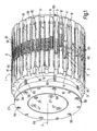
Figure 1 shows a schematic view in perspective of a preferred embodiment of the centring drum according to the present invention; -
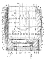
Figure 2 shows a substantially axial section of theFigure 1 centring drum; -
Figure 3 shows an exploded view in perspective of a detail inFigures 1 and2 . -
Number 1 in the accompanying drawings indicates as a whole a substantially cylindrical centring drum mounted for rotation about a respectivelongitudinal axis 2, and which provides for receiving two side byside rows 3 and 4 of double filters 5 - which rows are located on opposite sides of a substantially central reference plane T crosswise tolongitudinal axis 2, and are offset angularly about axis 2 - and for shuffling the tworows 3 and 4 through reference plane T to form a single row 6 centred with respect to reference plane T and comprising a succession ofdouble filters 5 positioned parallel toaxis 2 and spaced aboutaxis 2 with a spacing equal to half the spacing ofdouble filters 5 inrows 3 and 4. - As shown more clearly in
Figure 2 ,centring drum 1 comprises a substantially cylindrical shell 7 coaxial withlongitudinal axis 2, rotating aboutlongitudinal axis 2, and through which reference plane T extends. Externally, shell 7 comprises acylindrical surface 8, a central portion of which is fitted with a larger-diameter sleeve 9 centred with respect to reference plane T, bounded axially by twoannular shoulders 10, and bounded externally by a cylindrical surface 11 coaxial withlongitudinal axis 2 and having a number of substantially semicylindrical-section grooves 12, each defining a seat for a relativedouble filter 5. More specifically,grooves 12 are parallel tolongitudinal axis 2, are equally spaced aboutlongitudinal axis 2, extend through reference plane T, and each receive a respectivedouble filter 5 originally located entirely on one side of reference plane T. That is, if twoadjacent grooves 12 are considered in the example shown, the relativedouble filters 5 are originally located on opposite sides of reference plane T. - As shown in
Figure 2 , shell 7 is open at the rear, comprises a cylindricalinner surface 13 coaxial withlongitudinal axis 2, and is bounded at the front by anend wall 14 having aninner surface 15, through which is formed acylindrical cavity 16 coaxial withlongitudinal axis 2 and in turn comprising an end surface 17 having a through hole 18. Hole 18 is coaxial withlongitudinal axis 2, and connectscavity 16 to acavity 19 formed in anouter surface 20 ofend wall 14. - A rear portion of
inner surface 13 is fitted inside in fluidtight manner with the end of adrive shaft 21 having anaxial end appendix 22, the free end of which is fitted with acylindrical head 23 resting against end surface 17 ofcavity 16 and having acylindrical centring appendix 24 shorter in length than hole 18, and the outer surface of which mates with the inner surface of hole 18. -
Drive shaft 21 is connected angularly to shell 7 by means of acylindrical plate 25 located frontwards ofend wall 14, and which is housed partly insidecavity 19, is fixed angularly with respect to driveshaft 21 by means of apin 26, and is connected tohead 23 byaxial screws 27 whichgrip end wall 14 betweenhead 23 andplate 25. - As shown in
Figure 2 , the shell is associated with acentring device 28 comprising asuction circuit 29, astop device 30, and anadjusting device 31 for adjustingstop device 30. -
Suction circuit 29 comprises a known suction pump (not shown), the inlet of which is connected to adead conduit 32 formed alongdrive shaft 21 andaxial appendix 22, coaxially withlongitudinal axis 2; a chamber 33 defined, inside shell 7 and aboutaxial appendix 22, between the end ofdrive shaft 21 andend wall 14, and connected to conduit 32 byradial holes 34; and tworings radial holes 37 formed through shell 7 andsleeve 9, and each communicating with arespective groove 12. The tworings double filter 5 that can be accommodated oncentring drum 1; andholes 37 in eachring longitudinal axis 2 with a spacing equal to twice the spacing ofgrooves 12, and are offset, with respect toholes 37 in theother ring longitudinal axis 2, by a spacing equal to the spacing ofgrooves 12. Consequently, if onegroove 12 communicates with ahole 37 inring 35, the twoadjacent grooves 12 communicate withrespective holes 37 inring 36. -
Stop device 30 comprises tworings sleeve 9, withring 38 interposed between reference plane T andplate 25 and located on the opposite side ofring 35 to reference plane T, and have respectiveaxial fingers 40, each of which extends fromrelative ring other ring respective groove 12, at the end ofgroove 12 havingrelative hole 37, and is less than half the length ofgroove 12, but long enough to coverrelative hole 37 in any operating condition. Consequently,fingers 40 ofrings respective successions 41, 42 offingers 40, located on opposite sides of reference plane T;fingers 40 in eachsuccession 41, 42 are spaced aboutlongitudinal axis 2 with a spacing equal to twice the spacing ofgrooves 12, and are offset, with respect tofingers 40 in theother succession 42, 41 and aboutlongitudinal axis 2, by a spacing equal to the spacing ofgrooves 12; and, if onegroove 12 is engaged by afinger 40 insuccession 41, the twoadjacent grooves 12 are engaged byrespective fingers 40 in succession 42. - In the accompanying drawings,
fingers 40 are shown forming one piece withrespective rings rings - Each
finger 40 has anend surface 43 facing reference plane T and defining a stop surface for a relativedouble filter 5 housed insiderelative groove 12, and has, on the side facing shell 7, anaxial groove 44 which communicates withrelative hole 37 in any operating condition, and which comes out throughend surface 43. - Adjusting
device 31 comprises anannular body 45 which is fixed inside anannular groove 46 formed on the periphery ofplate 25 coaxially withlongitudinal axis 2, and houses for rotation aring gear 47 coaxial withlongitudinal axis 2 and having external teeth meshing with a number of pinions 48 (three in the example shown, but which may be of any number) equally spaced aboutlongitudinal axis 2 and having axes parallel tolongitudinal axis 2, and with a number of pinions 49 (three in the example shown, but which may be of any number) equally spaced aboutlongitudinal axis 2, having axes parallel tolongitudinal axis 2, and alternating, alongring gear 47, withpinions 48. - Each
pinion 48 is fitted to the end of arespective screw 50 which projects fromannular body 45, in a direction parallel tolongitudinal axis 2, and engages a relative threadedhole 51 formed axially inring 38, so as to define, withring 38, a relative screw-nut screw coupling 52. - Each
pinion 49 is fitted to the end of arespective rod 53 which projects fromannular body 45, in a direction parallel tolongitudinal axis 2, engages a relativeaxial groove 54 formed in the inner surface ofring 38, engages a relative axial through hole 55 formed in the thickness ofsleeve 9, and has a threadedend 56 engaging a relative threadedhole 57 formed axially inring 39, so as to define, withring 39, a relative screw-nut screw coupling 58. - Each
pinion wrench socket 59 accessible from the outside to permit manual operation ofring gear 47. - In actual use, before two
rows 3 and 4 ofdouble filters 5 are fed intorespective grooves 12 on opposite sides of reference plane T oncentring drum 1, adjustingdevice 31 is set to moverings end surfaces 43 ofrelative fingers 40 and reference plane T equals half the length of thedouble filters 5 to be fed ontocentring drum 1. In the case of centringdrum 1 described, adjustingdevice 31 is set by manually rotating one ofpinions pinions ring gear 47 about longitudinal axis, thus rotating all ofpinions rings end surfaces 43 ofrelative fingers 40 alongrelative grooves 12 and with respect to reference plane T. - Consequently, any change in format involving the use of
double filters 5 of different length can be made relatively quickly, and with no need to dismantle and reassemble any part ofcentring drum 1. - In variations not shown, adjusting
device 31 may obviously be powered in various ways, e.g. by powering one ofpinions ring gear 47. In which case, adjustingdevice 31 may conveniently be controlled automatically by a format-change control unit on the basis of memorized format data. - Each
double filter 5 fed ontocentring drum 1 set as described above is positioned inside arelative groove 12, on the opposite side ofend surface 43 ofrelative finger 40 to reference plane T and aligned transversely with the otherdouble filters 5 inrelative row 3, 4, and almost immediately is pushed axially, by the air sucked throughgroove 44 ofrelative finger 40, ontorelative end surface 43 ofrelative finger 40 and into a position aligned transversely with the previousdouble filters 5 to form row 6. - The embodiment described relates to a
centring drum 1 for receiving two rows ofdouble filters 5. Obviously, in the case of more than two, e.g. three or four, rows ofdouble filters 5,centring device 28 must be modified. - For example, in the case of three rows of
double filters 5, one of the tworings e.g. ring 38, is provided with two successions offingers 40, and the other with only one succession offingers 40.Fingers 40 in the two successions connected toring 38 will be of different lengths, so as to keep thedouble filters 5 in one of the relative two rows centred with respect to reference plane T, and to enable thedouble filters 5 in the other of the relative two rows to move axially into a centred position with respect to reference plane T. - In the case of four rows of
double filters 5, bothrings fingers 40.
Claims (10)
- A centring drum for filter assembly machines, the centring drum (1) comprising:a substantially cylindrical shell (7) having a longitudinal axis (2) and a transverse reference plane (T), and rotating about said longitudinal axis (2);a succession of seats (12) formed, parallel to said longitudinal axis (2), on the outside of said shell (7) and equally spaced about said longitudinal axis (2); wherein each.said seat (12) receives a respective filter portion (5), and at least some of said filter portions (5) are offset laterally, along the relative said seats (12), with respect to said reference plane (T); andcentring means (28) which act on each laterally offset filter portion (5) to centre it, along the relative seat (12), with respect to said reference plane (T); wherein the centring means (28) are fitted to said shell (7) to rotate with the shell (7) about said longitudinal axis (2), and comprise, for each said seat (12), a stop member (40) located on a respective side of said reference plane (T) to define a centred position of the relative said filter portion (5), and push means (29) for moving the relative said filter portion (5) axially onto the relative said stop member (40) ;the centring drum is characterized in that the stop members (40) define a first and a second succession (41, 42) of stop members (40), which successions (41, 42) are located on opposite sides of said reference plane (T) and are intercalated so as if one seat (12) is engaged by a stop member (40) of a succession (41; 42), the two adjacent seats (12) are engaged by two stop members (40) of the other succession (42; 41); and adjusting means (31) are provided to move said two successions (41, 42) equally and oppositely along said longitudinal axis (2).
- A drum as claimed in Claim 1, wherein said push means (29) are pneumatic means.
- A drum as claimed in Claim 1 or 2, wherein said push means (29) are suction means which come out inside the relative said seat (12), on the same side of said reference plane (T) as the relative said stop member (40).
- A drum as claimed in any one of Claims 1 to 3, wherein each said stop member (40) comprises a finger (40) housed in axially sliding manner inside the relative said seat (12), and having an end surface (43) facing said reference plane (T) and defining a stop surface for the relative said filter portion (5).
- A drum as claimed in Claim 4, wherein said push means (29) are suction means which come out inside the relative said seat (12) at said end surface (43).
- A drum as claimed in Claim 5, wherein said push means (29) comprise a suction hole (37) which comes out inside the relative said seat (12), beneath the relative said finger (40); and a groove (44) formed along said finger (40), communicating with the relative said suction hole (37), and terminating at said end surface (43).
- A drum as claimed in one of the foregoing Claims, wherein the stop members (40) in each said succession are integral with one another.
- A drum as claimed in Claims 4 and 7, wherein said first and said second succession (41, 42) respectively comprise a first and a second annular body (38, 39) which are coaxial with said longitudinal axis (2), are located axially outwards of said seats (12) and on opposite sides of said reference plane (T), and connect the relative said fingers (40) to one another; said first and said second annular body (38, 39) being movable axially with respect to said shell (7), and being fitted to said adjusting means (31).
- A drum as claimed in Claim 8, wherein said adjusting means (31) comprise at least one first screw-nut screw coupling (52), in turn comprising a screw (50) extending parallel to said longitudinal axis (2), and a nut screw (51) formed through said first annular body (38) ; at least one second screw-nut screw coupling (58) operating in the opposite direction to said first screw-nut screw coupling (52), and in turn comprising a screw (56) extending parallel to said longitudinal axis (2), and a nut screw (57) formed through said second annular body (39) ; and a ring gear (47) coaxial with said shell (7) and mounted to rotate, with respect to said shell (7), about said longitudinal axis (2); each said screw (50; 56) being fitted integrally with a relative pinion (48; 49); each said pinion (48; 49) meshing with said ring gear (47) ; and actuating means (59) being provided to impart to said ring gear (47) a given, adjustable rotation about said longitudinal axis (2).
- A drum as claimed in any one of Claims 1 to 9, wherein said filter portions (5) define a double filter (5) for cigarettes.
Applications Claiming Priority (2)
| Application Number | Priority Date | Filing Date | Title |
|---|---|---|---|
| IT000683A ITBO20030683A1 (en) | 2003-11-17 | 2003-11-17 | DRUM CENTERER FOR FILTER MACHINES |
| PCT/EP2004/052981 WO2005046366A1 (en) | 2003-11-17 | 2004-11-16 | Centring drum for filter assembly machines |
Publications (2)
| Publication Number | Publication Date |
|---|---|
| EP1703812A1 EP1703812A1 (en) | 2006-09-27 |
| EP1703812B1 true EP1703812B1 (en) | 2008-04-02 |
Family
ID=34586974
Family Applications (1)
| Application Number | Title | Priority Date | Filing Date |
|---|---|---|---|
| EP04816329A Expired - Lifetime EP1703812B1 (en) | 2003-11-17 | 2004-11-16 | Centring drum for filter assembly machines |
Country Status (8)
| Country | Link |
|---|---|
| US (1) | US7837025B2 (en) |
| EP (1) | EP1703812B1 (en) |
| JP (1) | JP4495164B2 (en) |
| CN (1) | CN100463620C (en) |
| AT (1) | ATE390858T1 (en) |
| DE (1) | DE602004012895T2 (en) |
| IT (1) | ITBO20030683A1 (en) |
| WO (1) | WO2005046366A1 (en) |
Cited By (1)
| Publication number | Priority date | Publication date | Assignee | Title |
|---|---|---|---|---|
| EP4328027A2 (en) | 2020-12-02 | 2024-02-28 | G.D Societa' Per Azioni | Operating machine for processing smoking articles with a pneumatic component made using additive manufacturing |
Families Citing this family (18)
| Publication number | Priority date | Publication date | Assignee | Title |
|---|---|---|---|---|
| DE102007024271B4 (en) * | 2007-05-23 | 2009-02-12 | Hauni Maschinenbau Aktiengesellschaft | conveyor drum |
| DE102008063847B4 (en) * | 2008-12-19 | 2010-08-05 | Hauni Maschinenbau Ag | Swash plate, conveyor drum and machine of the tobacco processing industry |
| IT1400272B1 (en) * | 2010-06-04 | 2013-05-24 | Ima Safe S R L Unipersonale | PADS DISTRIBUTION MACHINE AND ITS PROCEDURE |
| DE102012001831B4 (en) * | 2012-02-01 | 2015-03-19 | Hochland Se | Method and device for separating and stacking food slices |
| DE102013210634A1 (en) * | 2013-06-07 | 2014-12-11 | Hauni Maschinenbau Ag | Sliding drum for a machine of the tobacco processing industry |
| GB201406267D0 (en) * | 2014-04-08 | 2014-05-21 | British American Tobacco Co | A rolling drum assembly for use in smoking article manufacture |
| GB201407582D0 (en) * | 2014-04-30 | 2014-06-11 | British American Tobacco Co | A tobacco industry rod assembly apparatus |
| GB201419197D0 (en) * | 2014-10-29 | 2014-12-10 | British American Tobacco Co | A rod article distribution apparatus |
| CN104842390A (en) * | 2014-12-24 | 2015-08-19 | 王鑫 | Novel paper cutting device |
| PL412017A1 (en) * | 2015-04-21 | 2016-10-24 | International Tobacco Machinery Poland Spółka Z Ograniczoną Odpowiedzialnością | Device for centring the bar-like article or the group of bar-like products |
| DE102015113820A1 (en) * | 2015-08-20 | 2017-02-23 | Hauni Maschinenbau Gmbh | Sliding drum of the tobacco processing industry |
| PL414414A1 (en) * | 2015-10-20 | 2017-04-24 | International Tobacco Machinery Poland Spółka Z Ograniczoną Odpowiedzialnością | Device and method for axial centring of the bar-like article or the group of bar-like articles and the multi-stage unit for cutting the bar-like article or the group of bar-like articles |
| CN107114822B (en) * | 2017-06-21 | 2018-07-13 | 龙岩烟草工业有限责任公司 | Cutter drum auxiliary dismounting device, cutter drum and cigarette machine |
| WO2019116196A1 (en) * | 2017-12-13 | 2019-06-20 | G.D S.P.A. | Compacting unit and method for the tobacco industry |
| DE102018104956A1 (en) * | 2018-03-05 | 2019-09-05 | Hauni Maschinenbau Gmbh | Conveyor drum of the tobacco processing industry |
| DE102018104957A1 (en) | 2018-03-05 | 2019-09-05 | Hauni Maschinenbau Gmbh | Sliding drum of the tobacco processing industry |
| IT201900014352A1 (en) * | 2019-08-08 | 2021-02-08 | Gd Spa | Conveyor and alignment method for rod-shaped items |
| CN117281291B (en) * | 2023-11-10 | 2025-08-19 | 襄阳申冠机电技术有限公司 | Rod-shaped object positioning and separating device |
Family Cites Families (7)
| Publication number | Priority date | Publication date | Assignee | Title |
|---|---|---|---|---|
| IT1157697B (en) * | 1982-09-10 | 1987-02-18 | Sasib Spa | DEVICE FOR WRAPPING THE UNION CLAMP AROUND THE GROUP CIGARETTE FILTER ASSEMBLED IN THE MANUFACTURE OF CIGARETTES WITH FILTER |
| JP3368038B2 (en) * | 1994-03-31 | 2003-01-20 | 日本たばこ産業株式会社 | Grading device for filter plug supply device |
| JP3368054B2 (en) | 1994-07-22 | 2003-01-20 | 日本たばこ産業株式会社 | Rod-shaped member receiving device |
| IT1309989B1 (en) * | 1999-06-29 | 2002-02-05 | Gd Spa | ROLLER HANDLING DEVICE IN AUTOMATIC MACHINES. |
| IT1320967B1 (en) | 2000-03-31 | 2003-12-18 | Gd Spa | SEPARATOR DRUM FOR AXIAL SPACING OF TWO CIGARETTE BITS BETWEEN THEIR COAXIALS IN A FILTER FEEDER MACHINE. |
| DE10146019A1 (en) * | 2001-09-18 | 2003-04-03 | Hauni Maschinenbau Ag | Production machine for multi-segmented filters, has various operating units, conveyor elements as drums |
| DE10156303A1 (en) | 2001-11-19 | 2003-06-26 | Focke & Co | Method and device for producing filter cigarettes |
-
2003
- 2003-11-17 IT IT000683A patent/ITBO20030683A1/en unknown
-
2004
- 2004-11-16 CN CNB2004800339087A patent/CN100463620C/en not_active Expired - Fee Related
- 2004-11-16 AT AT04816329T patent/ATE390858T1/en not_active IP Right Cessation
- 2004-11-16 WO PCT/EP2004/052981 patent/WO2005046366A1/en not_active Ceased
- 2004-11-16 EP EP04816329A patent/EP1703812B1/en not_active Expired - Lifetime
- 2004-11-16 US US10/579,589 patent/US7837025B2/en not_active Expired - Fee Related
- 2004-11-16 DE DE602004012895T patent/DE602004012895T2/en not_active Expired - Lifetime
- 2004-11-16 JP JP2006540448A patent/JP4495164B2/en not_active Expired - Fee Related
Cited By (1)
| Publication number | Priority date | Publication date | Assignee | Title |
|---|---|---|---|---|
| EP4328027A2 (en) | 2020-12-02 | 2024-02-28 | G.D Societa' Per Azioni | Operating machine for processing smoking articles with a pneumatic component made using additive manufacturing |
Also Published As
| Publication number | Publication date |
|---|---|
| WO2005046366A1 (en) | 2005-05-26 |
| CN1882257A (en) | 2006-12-20 |
| CN100463620C (en) | 2009-02-25 |
| EP1703812A1 (en) | 2006-09-27 |
| DE602004012895D1 (en) | 2008-05-15 |
| JP4495164B2 (en) | 2010-06-30 |
| ITBO20030683A1 (en) | 2005-05-18 |
| US7837025B2 (en) | 2010-11-23 |
| ATE390858T1 (en) | 2008-04-15 |
| US20070251533A1 (en) | 2007-11-01 |
| DE602004012895T2 (en) | 2009-04-02 |
| JP2007511234A (en) | 2007-05-10 |
Similar Documents
| Publication | Publication Date | Title |
|---|---|---|
| US7837025B2 (en) | Centring drum for filter assembly machines | |
| CN102112013B (en) | Conveying drum in tobacco-processing industry | |
| US5984851A (en) | Grading device, used in manufacture of filter plugs for cigarettes | |
| JPH01132367A (en) | Apparatus for manufacturing cigarette filter | |
| EP0674853B1 (en) | Filter plug feeding apparatus for a filter cigarette manufacturing machine | |
| CN105533801B (en) | Rotatable filter rod automatic processing device | |
| EP0679344B1 (en) | Aligning device used in manufacturing filter plugs for cigarettes | |
| US5031643A (en) | Pneumatic conveyor for rod-shaped articles of the tobacco processing industry and their components | |
| JPH0614760A (en) | Apparatus for moving cigarette in axial direction of machine for producing tobacco | |
| EP1421864B1 (en) | A unit for transferring cigarette sticks from a cigarette maker to a filter tip attachment | |
| US4746006A (en) | Filter cigarette manufacture | |
| EP1532879B1 (en) | Perfected drum for filter-tipped cigarette manufacturing machines | |
| US4913170A (en) | Axial cigarette displacing device | |
| US4438774A (en) | Cigarette conveying drums | |
| EP3544451B1 (en) | Method and drum for moving rod-shaped articles of the tobacco industry | |
| US4519405A (en) | Spacer device for filter fitting machine | |
| GB2090572A (en) | Cigarette conveying drums | |
| EP1800552A1 (en) | A unit for conveying tobacco products | |
| CN100443003C (en) | Step roller | |
| GB1565206A (en) | Suction conveyor drums for cigarettes and similar rodlike articles | |
| JP2004073150A (en) | Jiaozi preparation apparatus | |
| EP1883319B1 (en) | A unit for transferring sticks of rod material used to manufacture tobacco products | |
| US20070028933A1 (en) | Device for feeding filter rods in a filter tip attachment machine | |
| EP0722672B1 (en) | Rolling unit for producing filter-tipped cigarettes | |
| JP2013107220A (en) | Material supply device for injection molding machine |
Legal Events
| Date | Code | Title | Description |
|---|---|---|---|
| PUAI | Public reference made under article 153(3) epc to a published international application that has entered the european phase |
Free format text: ORIGINAL CODE: 0009012 |
|
| 17P | Request for examination filed |
Effective date: 20060606 |
|
| AK | Designated contracting states |
Kind code of ref document: A1 Designated state(s): AT BE BG CH CY CZ DE DK EE ES FI FR GB GR HU IE IS IT LI LU MC NL PL PT RO SE SI SK TR |
|
| DAX | Request for extension of the european patent (deleted) | ||
| GRAP | Despatch of communication of intention to grant a patent |
Free format text: ORIGINAL CODE: EPIDOSNIGR1 |
|
| GRAS | Grant fee paid |
Free format text: ORIGINAL CODE: EPIDOSNIGR3 |
|
| GRAA | (expected) grant |
Free format text: ORIGINAL CODE: 0009210 |
|
| RIN1 | Information on inventor provided before grant (corrected) |
Inventor name: DRAGHETTI, FIORENZO Inventor name: GOBBI, ALESSANDRO Inventor name: BERTINELLI, GIANLUCA Inventor name: ZANETTI, UMBERTO |
|
| AK | Designated contracting states |
Kind code of ref document: B1 Designated state(s): AT BE BG CH CY CZ DE DK EE ES FI FR GB GR HU IE IS IT LI LU MC NL PL PT RO SE SI SK TR |
|
| REG | Reference to a national code |
Ref country code: GB Ref legal event code: FG4D |
|
| REG | Reference to a national code |
Ref country code: CH Ref legal event code: EP Ref country code: IE Ref legal event code: FG4D |
|
| REF | Corresponds to: |
Ref document number: 602004012895 Country of ref document: DE Date of ref document: 20080515 Kind code of ref document: P |
|
| REG | Reference to a national code |
Ref country code: CH Ref legal event code: NV Representative=s name: HEPP, WENGER & RYFFEL AG |
|
| PG25 | Lapsed in a contracting state [announced via postgrant information from national office to epo] |
Ref country code: SI Free format text: LAPSE BECAUSE OF FAILURE TO SUBMIT A TRANSLATION OF THE DESCRIPTION OR TO PAY THE FEE WITHIN THE PRESCRIBED TIME-LIMIT Effective date: 20080402 |
|
| NLV1 | Nl: lapsed or annulled due to failure to fulfill the requirements of art. 29p and 29m of the patents act | ||
| PG25 | Lapsed in a contracting state [announced via postgrant information from national office to epo] |
Ref country code: NL Free format text: LAPSE BECAUSE OF FAILURE TO SUBMIT A TRANSLATION OF THE DESCRIPTION OR TO PAY THE FEE WITHIN THE PRESCRIBED TIME-LIMIT Effective date: 20080402 Ref country code: BG Free format text: LAPSE BECAUSE OF FAILURE TO SUBMIT A TRANSLATION OF THE DESCRIPTION OR TO PAY THE FEE WITHIN THE PRESCRIBED TIME-LIMIT Effective date: 20080702 Ref country code: PT Free format text: LAPSE BECAUSE OF FAILURE TO SUBMIT A TRANSLATION OF THE DESCRIPTION OR TO PAY THE FEE WITHIN THE PRESCRIBED TIME-LIMIT Effective date: 20080903 Ref country code: FI Free format text: LAPSE BECAUSE OF FAILURE TO SUBMIT A TRANSLATION OF THE DESCRIPTION OR TO PAY THE FEE WITHIN THE PRESCRIBED TIME-LIMIT Effective date: 20080402 Ref country code: ES Free format text: LAPSE BECAUSE OF FAILURE TO SUBMIT A TRANSLATION OF THE DESCRIPTION OR TO PAY THE FEE WITHIN THE PRESCRIBED TIME-LIMIT Effective date: 20080713 |
|
| PG25 | Lapsed in a contracting state [announced via postgrant information from national office to epo] |
Ref country code: PL Free format text: LAPSE BECAUSE OF FAILURE TO SUBMIT A TRANSLATION OF THE DESCRIPTION OR TO PAY THE FEE WITHIN THE PRESCRIBED TIME-LIMIT Effective date: 20080402 Ref country code: AT Free format text: LAPSE BECAUSE OF FAILURE TO SUBMIT A TRANSLATION OF THE DESCRIPTION OR TO PAY THE FEE WITHIN THE PRESCRIBED TIME-LIMIT Effective date: 20080402 |
|
| PG25 | Lapsed in a contracting state [announced via postgrant information from national office to epo] |
Ref country code: IS Free format text: LAPSE BECAUSE OF FAILURE TO SUBMIT A TRANSLATION OF THE DESCRIPTION OR TO PAY THE FEE WITHIN THE PRESCRIBED TIME-LIMIT Effective date: 20080802 |
|
| EN | Fr: translation not filed | ||
| PG25 | Lapsed in a contracting state [announced via postgrant information from national office to epo] |
Ref country code: SE Free format text: LAPSE BECAUSE OF FAILURE TO SUBMIT A TRANSLATION OF THE DESCRIPTION OR TO PAY THE FEE WITHIN THE PRESCRIBED TIME-LIMIT Effective date: 20080702 Ref country code: DK Free format text: LAPSE BECAUSE OF FAILURE TO SUBMIT A TRANSLATION OF THE DESCRIPTION OR TO PAY THE FEE WITHIN THE PRESCRIBED TIME-LIMIT Effective date: 20080402 Ref country code: CZ Free format text: LAPSE BECAUSE OF FAILURE TO SUBMIT A TRANSLATION OF THE DESCRIPTION OR TO PAY THE FEE WITHIN THE PRESCRIBED TIME-LIMIT Effective date: 20080402 |
|
| PLBE | No opposition filed within time limit |
Free format text: ORIGINAL CODE: 0009261 |
|
| STAA | Information on the status of an ep patent application or granted ep patent |
Free format text: STATUS: NO OPPOSITION FILED WITHIN TIME LIMIT |
|
| PG25 | Lapsed in a contracting state [announced via postgrant information from national office to epo] |
Ref country code: RO Free format text: LAPSE BECAUSE OF FAILURE TO SUBMIT A TRANSLATION OF THE DESCRIPTION OR TO PAY THE FEE WITHIN THE PRESCRIBED TIME-LIMIT Effective date: 20080402 Ref country code: BE Free format text: LAPSE BECAUSE OF FAILURE TO SUBMIT A TRANSLATION OF THE DESCRIPTION OR TO PAY THE FEE WITHIN THE PRESCRIBED TIME-LIMIT Effective date: 20080402 Ref country code: SK Free format text: LAPSE BECAUSE OF FAILURE TO SUBMIT A TRANSLATION OF THE DESCRIPTION OR TO PAY THE FEE WITHIN THE PRESCRIBED TIME-LIMIT Effective date: 20080402 |
|
| 26N | No opposition filed |
Effective date: 20090106 |
|
| PG25 | Lapsed in a contracting state [announced via postgrant information from national office to epo] |
Ref country code: FR Free format text: LAPSE BECAUSE OF FAILURE TO SUBMIT A TRANSLATION OF THE DESCRIPTION OR TO PAY THE FEE WITHIN THE PRESCRIBED TIME-LIMIT Effective date: 20090123 Ref country code: EE Free format text: LAPSE BECAUSE OF FAILURE TO SUBMIT A TRANSLATION OF THE DESCRIPTION OR TO PAY THE FEE WITHIN THE PRESCRIBED TIME-LIMIT Effective date: 20080402 |
|
| PG25 | Lapsed in a contracting state [announced via postgrant information from national office to epo] |
Ref country code: MC Free format text: LAPSE BECAUSE OF NON-PAYMENT OF DUE FEES Effective date: 20081130 |
|
| PG25 | Lapsed in a contracting state [announced via postgrant information from national office to epo] |
Ref country code: IT Free format text: LAPSE BECAUSE OF FAILURE TO SUBMIT A TRANSLATION OF THE DESCRIPTION OR TO PAY THE FEE WITHIN THE PRESCRIBED TIME-LIMIT Effective date: 20080402 |
|
| PG25 | Lapsed in a contracting state [announced via postgrant information from national office to epo] |
Ref country code: CY Free format text: LAPSE BECAUSE OF FAILURE TO SUBMIT A TRANSLATION OF THE DESCRIPTION OR TO PAY THE FEE WITHIN THE PRESCRIBED TIME-LIMIT Effective date: 20080402 |
|
| PG25 | Lapsed in a contracting state [announced via postgrant information from national office to epo] |
Ref country code: IE Free format text: LAPSE BECAUSE OF NON-PAYMENT OF DUE FEES Effective date: 20081117 |
|
| PGFP | Annual fee paid to national office [announced via postgrant information from national office to epo] |
Ref country code: CH Payment date: 20091124 Year of fee payment: 6 |
|
| PG25 | Lapsed in a contracting state [announced via postgrant information from national office to epo] |
Ref country code: LU Free format text: LAPSE BECAUSE OF NON-PAYMENT OF DUE FEES Effective date: 20081116 Ref country code: HU Free format text: LAPSE BECAUSE OF FAILURE TO SUBMIT A TRANSLATION OF THE DESCRIPTION OR TO PAY THE FEE WITHIN THE PRESCRIBED TIME-LIMIT Effective date: 20081003 |
|
| PG25 | Lapsed in a contracting state [announced via postgrant information from national office to epo] |
Ref country code: TR Free format text: LAPSE BECAUSE OF FAILURE TO SUBMIT A TRANSLATION OF THE DESCRIPTION OR TO PAY THE FEE WITHIN THE PRESCRIBED TIME-LIMIT Effective date: 20080402 |
|
| PG25 | Lapsed in a contracting state [announced via postgrant information from national office to epo] |
Ref country code: GR Free format text: LAPSE BECAUSE OF FAILURE TO SUBMIT A TRANSLATION OF THE DESCRIPTION OR TO PAY THE FEE WITHIN THE PRESCRIBED TIME-LIMIT Effective date: 20080703 |
|
| REG | Reference to a national code |
Ref country code: CH Ref legal event code: PL |
|
| PG25 | Lapsed in a contracting state [announced via postgrant information from national office to epo] |
Ref country code: LI Free format text: LAPSE BECAUSE OF NON-PAYMENT OF DUE FEES Effective date: 20101130 Ref country code: CH Free format text: LAPSE BECAUSE OF NON-PAYMENT OF DUE FEES Effective date: 20101130 |
|
| PGFP | Annual fee paid to national office [announced via postgrant information from national office to epo] |
Ref country code: GB Payment date: 20121126 Year of fee payment: 9 |
|
| GBPC | Gb: european patent ceased through non-payment of renewal fee |
Effective date: 20131116 |
|
| PG25 | Lapsed in a contracting state [announced via postgrant information from national office to epo] |
Ref country code: GB Free format text: LAPSE BECAUSE OF NON-PAYMENT OF DUE FEES Effective date: 20131116 |
|
| PGFP | Annual fee paid to national office [announced via postgrant information from national office to epo] |
Ref country code: DE Payment date: 20231129 Year of fee payment: 20 |
|
| REG | Reference to a national code |
Ref country code: DE Ref legal event code: R071 Ref document number: 602004012895 Country of ref document: DE |