EP1703534A2 - High total transmittance alumina discharge vessels having submicron grain size - Google Patents
High total transmittance alumina discharge vessels having submicron grain size Download PDFInfo
- Publication number
- EP1703534A2 EP1703534A2 EP06002661A EP06002661A EP1703534A2 EP 1703534 A2 EP1703534 A2 EP 1703534A2 EP 06002661 A EP06002661 A EP 06002661A EP 06002661 A EP06002661 A EP 06002661A EP 1703534 A2 EP1703534 A2 EP 1703534A2
- Authority
- EP
- European Patent Office
- Prior art keywords
- discharge vessel
- submicron
- total transmittance
- mgo
- transmittance
- Prior art date
- Legal status (The legal status is an assumption and is not a legal conclusion. Google has not performed a legal analysis and makes no representation as to the accuracy of the status listed.)
- Withdrawn
Links
Images

Classifications
-
- C—CHEMISTRY; METALLURGY
- C04—CEMENTS; CONCRETE; ARTIFICIAL STONE; CERAMICS; REFRACTORIES
- C04B—LIME, MAGNESIA; SLAG; CEMENTS; COMPOSITIONS THEREOF, e.g. MORTARS, CONCRETE OR LIKE BUILDING MATERIALS; ARTIFICIAL STONE; CERAMICS; REFRACTORIES; TREATMENT OF NATURAL STONE
- C04B35/00—Shaped ceramic products characterised by their composition; Ceramics compositions; Processing powders of inorganic compounds preparatory to the manufacturing of ceramic products
- C04B35/622—Forming processes; Processing powders of inorganic compounds preparatory to the manufacturing of ceramic products
- C04B35/64—Burning or sintering processes
- C04B35/645—Pressure sintering
- C04B35/6455—Hot isostatic pressing
-
- C—CHEMISTRY; METALLURGY
- C04—CEMENTS; CONCRETE; ARTIFICIAL STONE; CERAMICS; REFRACTORIES
- C04B—LIME, MAGNESIA; SLAG; CEMENTS; COMPOSITIONS THEREOF, e.g. MORTARS, CONCRETE OR LIKE BUILDING MATERIALS; ARTIFICIAL STONE; CERAMICS; REFRACTORIES; TREATMENT OF NATURAL STONE
- C04B35/00—Shaped ceramic products characterised by their composition; Ceramics compositions; Processing powders of inorganic compounds preparatory to the manufacturing of ceramic products
- C04B35/01—Shaped ceramic products characterised by their composition; Ceramics compositions; Processing powders of inorganic compounds preparatory to the manufacturing of ceramic products based on oxide ceramics
- C04B35/10—Shaped ceramic products characterised by their composition; Ceramics compositions; Processing powders of inorganic compounds preparatory to the manufacturing of ceramic products based on oxide ceramics based on aluminium oxide
- C04B35/111—Fine ceramics
- C04B35/115—Translucent or transparent products
-
- H—ELECTRICITY
- H01—ELECTRIC ELEMENTS
- H01J—ELECTRIC DISCHARGE TUBES OR DISCHARGE LAMPS
- H01J61/00—Gas-discharge or vapour-discharge lamps
- H01J61/02—Details
- H01J61/30—Vessels; Containers
- H01J61/302—Vessels; Containers characterised by the material of the vessel
-
- H—ELECTRICITY
- H01—ELECTRIC ELEMENTS
- H01J—ELECTRIC DISCHARGE TUBES OR DISCHARGE LAMPS
- H01J9/00—Apparatus or processes specially adapted for the manufacture, installation, removal, maintenance of electric discharge tubes, discharge lamps, or parts thereof; Recovery of material from discharge tubes or lamps
- H01J9/24—Manufacture or joining of vessels, leading-in conductors or bases
- H01J9/245—Manufacture or joining of vessels, leading-in conductors or bases specially adapted for gas discharge tubes or lamps
- H01J9/247—Manufacture or joining of vessels, leading-in conductors or bases specially adapted for gas discharge tubes or lamps specially adapted for gas-discharge lamps
-
- C—CHEMISTRY; METALLURGY
- C04—CEMENTS; CONCRETE; ARTIFICIAL STONE; CERAMICS; REFRACTORIES
- C04B—LIME, MAGNESIA; SLAG; CEMENTS; COMPOSITIONS THEREOF, e.g. MORTARS, CONCRETE OR LIKE BUILDING MATERIALS; ARTIFICIAL STONE; CERAMICS; REFRACTORIES; TREATMENT OF NATURAL STONE
- C04B2235/00—Aspects relating to ceramic starting mixtures or sintered ceramic products
- C04B2235/02—Composition of constituents of the starting material or of secondary phases of the final product
- C04B2235/30—Constituents and secondary phases not being of a fibrous nature
- C04B2235/32—Metal oxides, mixed metal oxides, or oxide-forming salts thereof, e.g. carbonates, nitrates, (oxy)hydroxides, chlorides
- C04B2235/3205—Alkaline earth oxides or oxide forming salts thereof, e.g. beryllium oxide
- C04B2235/3206—Magnesium oxides or oxide-forming salts thereof
-
- C—CHEMISTRY; METALLURGY
- C04—CEMENTS; CONCRETE; ARTIFICIAL STONE; CERAMICS; REFRACTORIES
- C04B—LIME, MAGNESIA; SLAG; CEMENTS; COMPOSITIONS THEREOF, e.g. MORTARS, CONCRETE OR LIKE BUILDING MATERIALS; ARTIFICIAL STONE; CERAMICS; REFRACTORIES; TREATMENT OF NATURAL STONE
- C04B2235/00—Aspects relating to ceramic starting mixtures or sintered ceramic products
- C04B2235/02—Composition of constituents of the starting material or of secondary phases of the final product
- C04B2235/50—Constituents or additives of the starting mixture chosen for their shape or used because of their shape or their physical appearance
- C04B2235/54—Particle size related information
- C04B2235/5418—Particle size related information expressed by the size of the particles or aggregates thereof
- C04B2235/5445—Particle size related information expressed by the size of the particles or aggregates thereof submicron sized, i.e. from 0,1 to 1 micron
-
- C—CHEMISTRY; METALLURGY
- C04—CEMENTS; CONCRETE; ARTIFICIAL STONE; CERAMICS; REFRACTORIES
- C04B—LIME, MAGNESIA; SLAG; CEMENTS; COMPOSITIONS THEREOF, e.g. MORTARS, CONCRETE OR LIKE BUILDING MATERIALS; ARTIFICIAL STONE; CERAMICS; REFRACTORIES; TREATMENT OF NATURAL STONE
- C04B2235/00—Aspects relating to ceramic starting mixtures or sintered ceramic products
- C04B2235/65—Aspects relating to heat treatments of ceramic bodies such as green ceramics or pre-sintered ceramics, e.g. burning, sintering or melting processes
- C04B2235/652—Reduction treatment
-
- C—CHEMISTRY; METALLURGY
- C04—CEMENTS; CONCRETE; ARTIFICIAL STONE; CERAMICS; REFRACTORIES
- C04B—LIME, MAGNESIA; SLAG; CEMENTS; COMPOSITIONS THEREOF, e.g. MORTARS, CONCRETE OR LIKE BUILDING MATERIALS; ARTIFICIAL STONE; CERAMICS; REFRACTORIES; TREATMENT OF NATURAL STONE
- C04B2235/00—Aspects relating to ceramic starting mixtures or sintered ceramic products
- C04B2235/65—Aspects relating to heat treatments of ceramic bodies such as green ceramics or pre-sintered ceramics, e.g. burning, sintering or melting processes
- C04B2235/656—Aspects relating to heat treatments of ceramic bodies such as green ceramics or pre-sintered ceramics, e.g. burning, sintering or melting processes characterised by specific heating conditions during heat treatment
-
- C—CHEMISTRY; METALLURGY
- C04—CEMENTS; CONCRETE; ARTIFICIAL STONE; CERAMICS; REFRACTORIES
- C04B—LIME, MAGNESIA; SLAG; CEMENTS; COMPOSITIONS THEREOF, e.g. MORTARS, CONCRETE OR LIKE BUILDING MATERIALS; ARTIFICIAL STONE; CERAMICS; REFRACTORIES; TREATMENT OF NATURAL STONE
- C04B2235/00—Aspects relating to ceramic starting mixtures or sintered ceramic products
- C04B2235/65—Aspects relating to heat treatments of ceramic bodies such as green ceramics or pre-sintered ceramics, e.g. burning, sintering or melting processes
- C04B2235/656—Aspects relating to heat treatments of ceramic bodies such as green ceramics or pre-sintered ceramics, e.g. burning, sintering or melting processes characterised by specific heating conditions during heat treatment
- C04B2235/6562—Heating rate
-
- C—CHEMISTRY; METALLURGY
- C04—CEMENTS; CONCRETE; ARTIFICIAL STONE; CERAMICS; REFRACTORIES
- C04B—LIME, MAGNESIA; SLAG; CEMENTS; COMPOSITIONS THEREOF, e.g. MORTARS, CONCRETE OR LIKE BUILDING MATERIALS; ARTIFICIAL STONE; CERAMICS; REFRACTORIES; TREATMENT OF NATURAL STONE
- C04B2235/00—Aspects relating to ceramic starting mixtures or sintered ceramic products
- C04B2235/65—Aspects relating to heat treatments of ceramic bodies such as green ceramics or pre-sintered ceramics, e.g. burning, sintering or melting processes
- C04B2235/656—Aspects relating to heat treatments of ceramic bodies such as green ceramics or pre-sintered ceramics, e.g. burning, sintering or melting processes characterised by specific heating conditions during heat treatment
- C04B2235/6567—Treatment time
-
- C—CHEMISTRY; METALLURGY
- C04—CEMENTS; CONCRETE; ARTIFICIAL STONE; CERAMICS; REFRACTORIES
- C04B—LIME, MAGNESIA; SLAG; CEMENTS; COMPOSITIONS THEREOF, e.g. MORTARS, CONCRETE OR LIKE BUILDING MATERIALS; ARTIFICIAL STONE; CERAMICS; REFRACTORIES; TREATMENT OF NATURAL STONE
- C04B2235/00—Aspects relating to ceramic starting mixtures or sintered ceramic products
- C04B2235/65—Aspects relating to heat treatments of ceramic bodies such as green ceramics or pre-sintered ceramics, e.g. burning, sintering or melting processes
- C04B2235/658—Atmosphere during thermal treatment
-
- C—CHEMISTRY; METALLURGY
- C04—CEMENTS; CONCRETE; ARTIFICIAL STONE; CERAMICS; REFRACTORIES
- C04B—LIME, MAGNESIA; SLAG; CEMENTS; COMPOSITIONS THEREOF, e.g. MORTARS, CONCRETE OR LIKE BUILDING MATERIALS; ARTIFICIAL STONE; CERAMICS; REFRACTORIES; TREATMENT OF NATURAL STONE
- C04B2235/00—Aspects relating to ceramic starting mixtures or sintered ceramic products
- C04B2235/65—Aspects relating to heat treatments of ceramic bodies such as green ceramics or pre-sintered ceramics, e.g. burning, sintering or melting processes
- C04B2235/658—Atmosphere during thermal treatment
- C04B2235/6582—Hydrogen containing atmosphere
-
- C—CHEMISTRY; METALLURGY
- C04—CEMENTS; CONCRETE; ARTIFICIAL STONE; CERAMICS; REFRACTORIES
- C04B—LIME, MAGNESIA; SLAG; CEMENTS; COMPOSITIONS THEREOF, e.g. MORTARS, CONCRETE OR LIKE BUILDING MATERIALS; ARTIFICIAL STONE; CERAMICS; REFRACTORIES; TREATMENT OF NATURAL STONE
- C04B2235/00—Aspects relating to ceramic starting mixtures or sintered ceramic products
- C04B2235/65—Aspects relating to heat treatments of ceramic bodies such as green ceramics or pre-sintered ceramics, e.g. burning, sintering or melting processes
- C04B2235/658—Atmosphere during thermal treatment
- C04B2235/6583—Oxygen containing atmosphere, e.g. with changing oxygen pressures
- C04B2235/6584—Oxygen containing atmosphere, e.g. with changing oxygen pressures at an oxygen percentage below that of air
-
- C—CHEMISTRY; METALLURGY
- C04—CEMENTS; CONCRETE; ARTIFICIAL STONE; CERAMICS; REFRACTORIES
- C04B—LIME, MAGNESIA; SLAG; CEMENTS; COMPOSITIONS THEREOF, e.g. MORTARS, CONCRETE OR LIKE BUILDING MATERIALS; ARTIFICIAL STONE; CERAMICS; REFRACTORIES; TREATMENT OF NATURAL STONE
- C04B2235/00—Aspects relating to ceramic starting mixtures or sintered ceramic products
- C04B2235/65—Aspects relating to heat treatments of ceramic bodies such as green ceramics or pre-sintered ceramics, e.g. burning, sintering or melting processes
- C04B2235/658—Atmosphere during thermal treatment
- C04B2235/6588—Water vapor containing atmospheres
-
- C—CHEMISTRY; METALLURGY
- C04—CEMENTS; CONCRETE; ARTIFICIAL STONE; CERAMICS; REFRACTORIES
- C04B—LIME, MAGNESIA; SLAG; CEMENTS; COMPOSITIONS THEREOF, e.g. MORTARS, CONCRETE OR LIKE BUILDING MATERIALS; ARTIFICIAL STONE; CERAMICS; REFRACTORIES; TREATMENT OF NATURAL STONE
- C04B2235/00—Aspects relating to ceramic starting mixtures or sintered ceramic products
- C04B2235/65—Aspects relating to heat treatments of ceramic bodies such as green ceramics or pre-sintered ceramics, e.g. burning, sintering or melting processes
- C04B2235/66—Specific sintering techniques, e.g. centrifugal sintering
- C04B2235/661—Multi-step sintering
- C04B2235/662—Annealing after sintering
- C04B2235/663—Oxidative annealing
-
- C—CHEMISTRY; METALLURGY
- C04—CEMENTS; CONCRETE; ARTIFICIAL STONE; CERAMICS; REFRACTORIES
- C04B—LIME, MAGNESIA; SLAG; CEMENTS; COMPOSITIONS THEREOF, e.g. MORTARS, CONCRETE OR LIKE BUILDING MATERIALS; ARTIFICIAL STONE; CERAMICS; REFRACTORIES; TREATMENT OF NATURAL STONE
- C04B2235/00—Aspects relating to ceramic starting mixtures or sintered ceramic products
- C04B2235/65—Aspects relating to heat treatments of ceramic bodies such as green ceramics or pre-sintered ceramics, e.g. burning, sintering or melting processes
- C04B2235/66—Specific sintering techniques, e.g. centrifugal sintering
- C04B2235/661—Multi-step sintering
- C04B2235/662—Annealing after sintering
- C04B2235/664—Reductive annealing
-
- C—CHEMISTRY; METALLURGY
- C04—CEMENTS; CONCRETE; ARTIFICIAL STONE; CERAMICS; REFRACTORIES
- C04B—LIME, MAGNESIA; SLAG; CEMENTS; COMPOSITIONS THEREOF, e.g. MORTARS, CONCRETE OR LIKE BUILDING MATERIALS; ARTIFICIAL STONE; CERAMICS; REFRACTORIES; TREATMENT OF NATURAL STONE
- C04B2235/00—Aspects relating to ceramic starting mixtures or sintered ceramic products
- C04B2235/70—Aspects relating to sintered or melt-casted ceramic products
- C04B2235/74—Physical characteristics
- C04B2235/78—Grain sizes and shapes, product microstructures, e.g. acicular grains, equiaxed grains, platelet-structures
- C04B2235/785—Submicron sized grains, i.e. from 0,1 to 1 micron
-
- C—CHEMISTRY; METALLURGY
- C04—CEMENTS; CONCRETE; ARTIFICIAL STONE; CERAMICS; REFRACTORIES
- C04B—LIME, MAGNESIA; SLAG; CEMENTS; COMPOSITIONS THEREOF, e.g. MORTARS, CONCRETE OR LIKE BUILDING MATERIALS; ARTIFICIAL STONE; CERAMICS; REFRACTORIES; TREATMENT OF NATURAL STONE
- C04B2235/00—Aspects relating to ceramic starting mixtures or sintered ceramic products
- C04B2235/70—Aspects relating to sintered or melt-casted ceramic products
- C04B2235/96—Properties of ceramic products, e.g. mechanical properties such as strength, toughness, wear resistance
- C04B2235/9646—Optical properties
-
- C—CHEMISTRY; METALLURGY
- C04—CEMENTS; CONCRETE; ARTIFICIAL STONE; CERAMICS; REFRACTORIES
- C04B—LIME, MAGNESIA; SLAG; CEMENTS; COMPOSITIONS THEREOF, e.g. MORTARS, CONCRETE OR LIKE BUILDING MATERIALS; ARTIFICIAL STONE; CERAMICS; REFRACTORIES; TREATMENT OF NATURAL STONE
- C04B2235/00—Aspects relating to ceramic starting mixtures or sintered ceramic products
- C04B2235/70—Aspects relating to sintered or melt-casted ceramic products
- C04B2235/96—Properties of ceramic products, e.g. mechanical properties such as strength, toughness, wear resistance
- C04B2235/9646—Optical properties
- C04B2235/9661—Colour
Definitions
- Translucent polycrystalline alumina (PCA) ceramic has made possible present-day high-pressure sodium (HPS) and ceramic metal halide lamps.
- HPS high-pressure sodium
- the arc discharge vessels in these applications must be capable of withstanding the high temperatures and pressures generated in an operating lamp as well be resistant to chemical attack by the fill materials.
- the discharge vessels are typically required to have >92% total transmittance in the visible wavelength region from about 400nm to about 700nm in order to be useable in commercial lighting applications.
- the discharge vessels are tubular, whereas for ceramic metal-halide lamps discharge vessels can range from a cylindrical shape to an approximately spherical shape (bulgy). Examples of these types of arc discharge vessels are given in European Patent Application No. 0 587 238 A1 and U.S. Patent No. 5,936,351 , respectively.
- the bulgy shape with its hemispherical ends yields a more uniform temperature distribution, resulting in reduced corrosion of the PCA by the lamp fills.
- PCA is translucent and not transparent, the use of PCA is limited to non-focused-beam lamp applications. Birefringent grain scattering is a major source of in-line transmittance loss in regular, sintered PCA, and in-line transmittance generally increases with increasing grain size. Reducing the grain size of sinter-HIPed PCA to the submicron range ( ⁇ 1 micrometer) shifts the scattering mechanism thereby decreasing grain birefringent scattering. In the submicron region, the in-line transmittance actually increases with decreasing grain size.
- the high in-line transmittance and mechanical strength of submicron-grained PCA are of interest for focused-beam, short-arc lamps, that offer improved luminance, efficacy, and color rendition.
- Magnesia is typically required as a sintering aid in the manufacture of alumina discharge vessels in order to retard grain growth and facilitate grain boundary diffusion while pinning grain boundaries.
- Submicron alumina ceramics based on nano-sized starting powders generally require a higher level MgO to reach full density than larger-grained (10-30 microns) alumina based on micron-sized starting powders. This is because nano-sized powder requires a higher level of MgO dopant to cover the surface of the finer particles.
- the MgO-based dopants e.g. ⁇ 200-300ppm
- the present invention overcomes the problem of low total transmittance in MgO-doped, submicron-grained alumina discharge vessels by a post-sinter-HIP anneal.
- the anneal is believed to alter the ionization and association states of the color centers, but not significantly change the total population of oxygen vacancies.
- the temperature, time, and partial pressure of oxygen of the annealing atmosphere are controlled so that significant portions of light-absorbing oxygen vacancies are converted to non-light-absorbing oxygen vacancies while at the same time a stable microstructure is maintained (no significant grain growth or precipitation of magnesium aluminate spinel second phase particles).
- the post-sinter HIP anneal effectively brings the total transmittance up to >92% in the range from about 400 nm to about 700 nm, a level suitable for commercial lamp applications.
- a method of making a ceramic discharge vessel comprising: (a) forming the discharge vessel with a submicron-grained alumina powder doped with MgO; (b) sinter-HIPing the discharge vessel; and (c) annealing the discharge vessel to increase the total transmittance of the discharge vessel to >92% in a wavelength range from about 400 nm to about 700 nm.
- a ceramic discharge vessel comprising a ceramic body comprised of a submicron-grained alumina doped with MgO, the discharge vessel having a total transmittance of greater than 92% in a wavelength range from about 400 nm to about 700 nm.
- Fig. 1 is a cross-sectional illustration of a bulgy-shaped discharge vessel according to this invention.
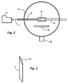
- Fig. 2 is a schematic illustration of an apparatus for measuring the total transmittance of a discharge vessel.
- Fig. 3 is a magnified view of the tapered end of the optical fiber used in the apparatus shown in Fig. 2.
- Fig. 1 is a cross-sectional illustration of an arc discharge vessel according to this invention.
- the arc discharge vessel 21 has a ceramic body 23 which is comprised of submicron-grained polycrystalline alumina doped with MgO.
- the ceramic body 23 has a total transmittance of greater than 92% in the wavelength range from about 400 nm to about 700 nm. More preferably, the total transmittance is greater than 95% over the same wavelength range.
- the body 23 defines an arc discharge cavity 25 and has two capillaries 27 extending outwardly in opposite directions from the discharge cavity 25.
- the thickness of the discharge cavity wall is about 0.8 mm.
- the capillaries are suitable for receiving, and sealing therein, electrode assemblies (not shown) which provide a conductive path for supplying electric power to the discharge vessel in order to strike and sustain an arc within the discharge cavity.
- electrode assemblies not shown
- FIG. 1 is a bulgy-shaped arc discharge vessel
- other suitable shapes for the arc discharge vessel of this invention include tubular arc discharge vessels similar to HPS arc tubes.
- Ceramic discharge vessels formed from a high-purity, finely divided aluminum oxide (alumina) powder may be consolidated by isopressing, slip casting, gel casting, or injection molding.
- the MgO dopant is generally added to the alumina powder prior to consolidation.
- the MgO dopant in the alumina powder ranges from about 200 ppm to about 800 ppm and the alumina powder has a mean particle size of about 150 nm.
- European Patent No. 0 650 184 B1 slip casting
- U.S. Patent No. 6,399,528 gel casting
- International Patent Application No. WO2004/007397 A1 (slip casting)
- European Patent Application No. EP 1 053 983 A2 isopressing.
- a fugitive core may be used in conjunction with a shaping (e.g., gel-casting) method to form the discharge vessel.
- a shaping e.g., gel-casting
- the green body containing the fugitive core such as wax
- the melting point of the core ⁇ 50°C for wax
- the binder materials are removed by slow heating in flowing air to 800°C. Too fast a heating rate may cause binder entrapment inside the densified powder compact, which causes the final sinter-HIPed sample to have a gray hue.
- Presintering is conducted at 1250-1270°C for 2h in air to reach a state of closed porosity.
- the presintered parts are hot isostatically pressed (HIPed) and sintered at 1270°C under ⁇ 10ksi argon.
- the total transmittance of the discharge vessels can be measured by illuminating one end of a small light pipe with a tungsten halogen lamp, placing the other end inside the hollow body, and measuring the total integrated flux of light passing out of the discharge vessel over the wavelength range from about 400 nm to about 700 nm.
- a schematic illustration of an apparatus for measuring the total transmittance is shown in Fig. 2.
- the sample 11 (in this case a tubular vessel) is mounted in a center region of integrating sphere 3 by supports 9 which hold the sample at opposite ends.
- a baffle 13 is positioned between the sample 1 and light detector 15.
- Optical fiber 7 is inserted through one of the supports 9 and into a center portion of the sample 11. Light is conducted from tungsten-halogen lamp 5 through the optical fiber 7.
- the light-emitting end 17 of the optical fiber 7, which is placed inside the sample, has a 20° taper with respect to the cylindrical axis of the fiber in order to scatter the emitted light to produce a nearly point source.
- the light emitted from the end of the optical fiber passes through the sample wall, is collected by the integrating sphere, and the total integrated flux is measured by the light detector, preferably an unfiltered silicon detector.
- the percentage of the total integrated flux transmitted through the sample represents the total transmittance of the sample.
- the total transmittance is effectively measured in the wavelength range from about 400nm to about 700nm.
- Suitable components for the apparatus are available from Labsphere, Inc. of North Sutton, NH.
- Both disks ( ⁇ 25mm diameter by 0.8mm thick) and 70W bulgy-shaped discharge vessels were made by sinter-HIPing.
- the starting submicron-grained alumina powder had a 150 nm mean particle size and was doped with 220 ppm MgO.
- the measured in-line transmittance was typically quite uniform within the same disk, and from disk to disk.
- the as-made, sinter-HiPed bodies had very few residual pores.
- the average grain size was about 0.5 microns. Grain size was determined by multiplying a factor of 1.5 to the intercept size measured using images acquired via scanning electron microscopy (SEM).
- the total transmittance values measured for the sinter-HIPed discharge vessels were relatively low, ranging from 69-87% with an average of about 77%.
- the spectrophotometer in-line transmittance of polished 0.8mm-thick disks at 600nm was measured as 50-55%. After annealing at 1025-11 50°C in air for various durations (2-4h), the total transmittance of sinter-HIPed, submicron-grained alumina vessels increased to 87-98% (Table 1).
- the scatter in the total transmittance may be attributed to the different levels of point defects, brought about by a location-specific, partial pressure of oxygen in the hot isostatic press.
- the total transmittance remained unchanged even after re-firing the vessels in wet hydrogen at 1100°C for 2h. Since wet hydrogen firing typically increases the transmittance of dry-hydrogen (very low P O2 )-sintered PCA, the fact that the total transmittance remained unchanged in this case indicates that the partial pressure of oxygen during HIPing was probably even more reducing than a dry H 2 environment (P O2 ⁇ 1 x1 0 -12 atm) .
- the annealing atmosphere is an inert gas, e.g., nitrogen or argon, that has a partial pressure of oxygen from about 1x10 -3 atm to about 1x10 -9 atm, and more preferably about 1x10 -5 atm to about 1x10 -7 atm.
- the annealing temperature may range preferably from about 1000°C to about 1150°C and the annealing time preferably may range from about 1 hour to about 20 hours. In a more preferred embodiment, the annealing temperature is about 1100°C and the annealing time is about 2 hours.
- Table 2 shows that after annealing at 1100°C for 2h in nitrogen, the total transmittance increased to >92%.
- a direct anneal for 20 hours at 1150°C in UHP-grade N 2 of an as-sinter-HIPed, submicron-grained discharge vessel increased total transmittance from 74.5% to 97.2%.
Landscapes
- Engineering & Computer Science (AREA)
- Chemical & Material Sciences (AREA)
- Manufacturing & Machinery (AREA)
- Ceramic Engineering (AREA)
- Materials Engineering (AREA)
- Structural Engineering (AREA)
- Organic Chemistry (AREA)
- Inorganic Chemistry (AREA)
- Compositions Of Oxide Ceramics (AREA)
- Vessels And Coating Films For Discharge Lamps (AREA)
- Manufacture Of Electron Tubes, Discharge Lamp Vessels, Lead-In Wires, And The Like (AREA)
Abstract
Description
- Translucent polycrystalline alumina (PCA) ceramic has made possible present-day high-pressure sodium (HPS) and ceramic metal halide lamps. The arc discharge vessels in these applications must be capable of withstanding the high temperatures and pressures generated in an operating lamp as well be resistant to chemical attack by the fill materials. In addition, the discharge vessels are typically required to have >92% total transmittance in the visible wavelength region from about 400nm to about 700nm in order to be useable in commercial lighting applications.
- In HPS lamps, the discharge vessels are tubular, whereas for ceramic metal-halide lamps discharge vessels can range from a cylindrical shape to an approximately spherical shape (bulgy). Examples of these types of arc discharge vessels are given in
European Patent Application No. 0 587 238 A1 andU.S. Patent No. 5,936,351 , respectively. The bulgy shape with its hemispherical ends yields a more uniform temperature distribution, resulting in reduced corrosion of the PCA by the lamp fills. - Because PCA is translucent and not transparent, the use of PCA is limited to non-focused-beam lamp applications. Birefringent grain scattering is a major source of in-line transmittance loss in regular, sintered PCA, and in-line transmittance generally increases with increasing grain size. Reducing the grain size of sinter-HIPed PCA to the submicron range (< 1 micrometer) shifts the scattering mechanism thereby decreasing grain birefringent scattering. In the submicron region, the in-line transmittance actually increases with decreasing grain size. The high in-line transmittance and mechanical strength of submicron-grained PCA are of interest for focused-beam, short-arc lamps, that offer improved luminance, efficacy, and color rendition.
- Magnesia (MgO) is typically required as a sintering aid in the manufacture of alumina discharge vessels in order to retard grain growth and facilitate grain boundary diffusion while pinning grain boundaries. Submicron alumina ceramics based on nano-sized starting powders generally require a higher level MgO to reach full density than larger-grained (10-30 microns) alumina based on micron-sized starting powders. This is because nano-sized powder requires a higher level of MgO dopant to cover the surface of the finer particles. Moreover, unlike the larger-grained alumina, the MgO-based dopants (e.g. ~200-300ppm) become completely dissolved in lattice and grain boundary region. As a result, high levels of color centers can form including a variety of single and double oxygen vacancies with one or two electrons. These color centers absorb light which result in a low total transmittance (~78%) for MgO-doped, submicron-grained alumina discharge vessels despite their high in-line transmittance.
- The present invention overcomes the problem of low total transmittance in MgO-doped, submicron-grained alumina discharge vessels by a post-sinter-HIP anneal. The anneal is believed to alter the ionization and association states of the color centers, but not significantly change the total population of oxygen vacancies. The temperature, time, and partial pressure of oxygen of the annealing atmosphere are controlled so that significant portions of light-absorbing oxygen vacancies are converted to non-light-absorbing oxygen vacancies while at the same time a stable microstructure is maintained (no significant grain growth or precipitation of magnesium aluminate spinel second phase particles). As a result, the post-sinter HIP anneal effectively brings the total transmittance up to >92% in the range from about 400 nm to about 700 nm, a level suitable for commercial lamp applications.
- In accordance with an aspect of the invention, there is provided a method of making a ceramic discharge vessel comprising: (a) forming the discharge vessel with a submicron-grained alumina powder doped with MgO; (b) sinter-HIPing the discharge vessel; and (c) annealing the discharge vessel to increase the total transmittance of the discharge vessel to >92% in a wavelength range from about 400 nm to about 700 nm.
- In accordance with another aspect of the invention, there is provided a ceramic discharge vessel comprising a ceramic body comprised of a submicron-grained alumina doped with MgO, the discharge vessel having a total transmittance of greater than 92% in a wavelength range from about 400 nm to about 700 nm.
- It is expected that additional co-doping of the PCA with ZrO2, Y2O3, Er2O3, Yb2O3, Sc2O3, etc., may alter the relative population of the point defects, but the problem of low total transmittance is expected to still exist because of the presence of MgO. Thus, the method of this invention should be useful to increase the total transmittance of such co-doped alumina ceramics.
- Fig. 1 is a cross-sectional illustration of a bulgy-shaped discharge vessel according to this invention.
- Fig. 2 is a schematic illustration of an apparatus for measuring the total transmittance of a discharge vessel.
- Fig. 3 is a magnified view of the tapered end of the optical fiber used in the apparatus shown in Fig. 2.
- For a better understanding of the present invention, together with other and further objects, advantages and capabilities thereof, reference is made to the following disclosure and appended claims taken in conjunction with the above-described drawings.
- Fig. 1 is a cross-sectional illustration of an arc discharge vessel according to this invention. The
arc discharge vessel 21 has aceramic body 23 which is comprised of submicron-grained polycrystalline alumina doped with MgO. Theceramic body 23 has a total transmittance of greater than 92% in the wavelength range from about 400 nm to about 700 nm. More preferably, the total transmittance is greater than 95% over the same wavelength range. Thebody 23 defines anarc discharge cavity 25 and has twocapillaries 27 extending outwardly in opposite directions from thedischarge cavity 25. Preferably, the thickness of the discharge cavity wall is about 0.8 mm. The capillaries are suitable for receiving, and sealing therein, electrode assemblies (not shown) which provide a conductive path for supplying electric power to the discharge vessel in order to strike and sustain an arc within the discharge cavity. Although the embodiment shown in Fig. 1 is a bulgy-shaped arc discharge vessel, other suitable shapes for the arc discharge vessel of this invention include tubular arc discharge vessels similar to HPS arc tubes. - Ceramic discharge vessels formed from a high-purity, finely divided aluminum oxide (alumina) powder may be consolidated by isopressing, slip casting, gel casting, or injection molding. The MgO dopant is generally added to the alumina powder prior to consolidation. Preferably, the MgO dopant in the alumina powder ranges from about 200 ppm to about 800 ppm and the alumina powder has a mean particle size of about 150 nm. The details of various methods of manufacturing green ceramic bodies for discharge vessels are described in, for example,
European Patent No. 0 650 184 B1 (slip casting),U.S. Patent No. 6,399,528 (gel casting), International Patent Application No.WO2004/007397 A1 (slip casting) andEuropean Patent Application No. EP 1 053 983 A2 (isopressing). - In the case of single-piece, hollow-core vessels, such as the bulgy-shaped discharge vessel, a fugitive core may be used in conjunction with a shaping (e.g., gel-casting) method to form the discharge vessel. To remove the core after shaping, the green body containing the fugitive core (such as wax) is heated slowly to the melting point of the core (~50°C for wax), allowing the molten core material to drip and flow out of the inside cavity. In a preferred method, the binder materials are removed by slow heating in flowing air to 800°C. Too fast a heating rate may cause binder entrapment inside the densified powder compact, which causes the final sinter-HIPed sample to have a gray hue. Presintering is conducted at 1250-1270°C for 2h in air to reach a state of closed porosity. The presintered parts are hot isostatically pressed (HIPed) and sintered at 1270°C under ~10ksi argon.
- The total transmittance of the discharge vessels can be measured by illuminating one end of a small light pipe with a tungsten halogen lamp, placing the other end inside the hollow body, and measuring the total integrated flux of light passing out of the discharge vessel over the wavelength range from about 400 nm to about 700 nm. A schematic illustration of an apparatus for measuring the total transmittance is shown in Fig. 2. The sample 11 (in this case a tubular vessel) is mounted in a center region of integrating
sphere 3 by supports 9 which hold the sample at opposite ends. Abaffle 13 is positioned between the sample 1 andlight detector 15.Optical fiber 7 is inserted through one of the supports 9 and into a center portion of thesample 11. Light is conducted from tungsten-halogen lamp 5 through theoptical fiber 7. As shown in Fig. 3, the light-emittingend 17 of theoptical fiber 7, which is placed inside the sample, has a 20° taper with respect to the cylindrical axis of the fiber in order to scatter the emitted light to produce a nearly point source. The light emitted from the end of the optical fiber passes through the sample wall, is collected by the integrating sphere, and the total integrated flux is measured by the light detector, preferably an unfiltered silicon detector. The percentage of the total integrated flux transmitted through the sample (compared to the total integrated flux emitted by the optical fiber alone) represents the total transmittance of the sample. Since the transmittance of the plastic optical fiber falls off at either end of the visible spectrum, i.e., less than about 400nm and greater than about 700nm, the total transmittance is effectively measured in the wavelength range from about 400nm to about 700nm. Suitable components for the apparatus are available from Labsphere, Inc. of North Sutton, NH. - Both disks (~25mm diameter by 0.8mm thick) and 70W bulgy-shaped discharge vessels were made by sinter-HIPing. The starting submicron-grained alumina powder had a 150 nm mean particle size and was doped with 220 ppm MgO. For the disks, the measured in-line transmittance was typically quite uniform within the same disk, and from disk to disk. The as-made, sinter-HiPed bodies had very few residual pores. The average grain size was about 0.5 microns. Grain size was determined by multiplying a factor of 1.5 to the intercept size measured using images acquired via scanning electron microscopy (SEM).
- The total transmittance values measured for the sinter-HIPed discharge vessels (polished or non-polished with a 0.8-mm wall thickness) were relatively low, ranging from 69-87% with an average of about 77%. The spectrophotometer in-line transmittance of polished 0.8mm-thick disks at 600nm was measured as 50-55%. After annealing at 1025-11 50°C in air for various durations (2-4h), the total transmittance of sinter-HIPed, submicron-grained alumina vessels increased to 87-98% (Table 1). The scatter in the total transmittance may be attributed to the different levels of point defects, brought about by a location-specific, partial pressure of oxygen in the hot isostatic press. Only about 10 out of 30 annealed vessels were fairly colorless, while most of them were brownish. This undesirable brown color is believed to be related to point defects. The brown color was one reason that air anneal could not increase the total transmittance to >92% for a number of vessels.
- The total transmittance remained unchanged even after re-firing the vessels in wet hydrogen at 1100°C for 2h. Since wet hydrogen firing typically increases the transmittance of dry-hydrogen (very low PO2)-sintered PCA, the fact that the total transmittance remained unchanged in this case indicates that the partial pressure of oxygen during HIPing was probably even more reducing than a dry H2 environment (PO2 < 1 x1 0-12 atm) .
- Annealing several of the air-annealed samples under a Ar-5ppm O2 atmosphere (PO2 = 5x10⁻⁶ atm) at 1100°C for 2 hours increased the total transmittance of the submicron-grained discharge vessels from 87-96% to 91-97% as shown in Table 1 (in-line transmittance is given in parentheses). These samples also became visually less colored. This means that, in terms of minimizing light-absorbing color centers, a PO2 of 5x10⁻⁶ atm in the anneal atmosphere is much better than that of air (PO2 ~ 0.2 atm) or wet hydrogen ((PO2 < 1X10-12 atm).
- The PO2 and temperature ranges in the post-sinter-HIP anneal are dictated by the thermodynamics of the point defects and their diffusion rates, whereas the annealing time and MgO levels depend on the thickness of the final part and the particle size of the starting powder. Preferably, the annealing atmosphere is an inert gas, e.g., nitrogen or argon, that has a partial pressure of oxygen from about 1x10⁻³ atm to about 1x10⁻⁹ atm, and more preferably about 1x10⁻⁵ atm to about 1x10⁻⁷ atm.
- If the anneal temperature is too high, spinel precipitates will form, in-line transmission loss occurs, and grains/residual pores grow to make the parts opaque. The annealing temperature may range preferably from about 1000°C to about 1150°C and the annealing time preferably may range from about 1 hour to about 20 hours. In a more preferred embodiment, the annealing temperature is about 1100°C and the annealing time is about 2 hours.
- Table 1 - Total Transmittance (%) (and In-line Transmittance (%)) Before and After Anneals
Samples As-made After Air Anneal Ar-5ppm O2 Anneal As-HIPed and polished 89.5 (2.03) 95.6 (1.85) 97.4 (2.02) As-HIPed and polished 81.3 (3.68) 93.4 (3.22) 96.1 (3.60) As-HIPed 73.1 (2.32) 90.6 (2.22) 93 (2.04) As-HIPed 73.6 (3.5) 88.8 (2.90) 94.3 (3.01) As-HIPed 71.4 (2.94) 89.9 (2.87) 94.1 (2.96) As-HIPed 69.1 (3.35) 89.2 (3.38) 94.8 (3.42) As-HIPed 74.4 (2.39) 89.4 (2.49) 96 (2.27) As-HIPed 69.5 (2.16) 88.9 (2.39) 94 (2.09) As-HIPed 76.1 (3.88) 90.3 (2.31) 96.4 (3.39) As-HIPed 77.6 (2.49) 89 (2.52) 93.2 (2.40) As-HIPed 72.6 (3.34) 88.5 (3.39) 94.4 (4.09) As-HIPed and polished 84.2 (3.82) 91.5 (3.83) 96.5 (3.66) As-HIPed 72.5 (2.24) 87 (3.10) 92.3 (3.72) As-HIPed 72.7(3.46) 89.6 (3.41) 95.5 (3.05) As-HIPed 78.7 (3.54) 87.6 (2.71) 91.4 (2.67) As-HIPed and polished 88 (4.23) 93 (3.90) 96.9 (4.6) As-HIPed and polished 85.8 (4.34) 92.7 (4.43) 97.2 (5.06) As-HIPed and polished 88.4 (6.52) 92.6 (5.00) 96.7 (5.60) - UHP-grade N2 gas typically contains 0.1-1ppm oxygen (PO2 = 0.1-1 x10⁻⁶ atm), and as such should be a favorable gas for anneal. Table 2 shows that after annealing at 1100°C for 2h in nitrogen, the total transmittance increased to >92%. Moreover, it was shown in another experiment that a direct anneal for 20 hours at 1150°C in UHP-grade N2 of an as-sinter-HIPed, submicron-grained discharge vessel increased total transmittance from 74.5% to 97.2%.
-
Table 2 - Total Transmittance (%) (and In-line Transmittance (%)) Before and After Various Anneals Samples As sinter-HIPed After Air Anneal After Ar-5ppm O2 Anneal After UHP-grade N2 Anneal As-HIPed 73.1 (2.32) 90.6 (2.22) 93 (2.04) 93.9 (4.40) As-HIPed 78.7 (3.54) 87.6 (2.71) 91.4 (2.67) 92.2 (2.56) As-HIPed and polished 82.9 (3.74) 92.5 (3.65) 96.7 (4.05) 98.1 (4.16) As-HIPed and polished 87.5 (4.23) 92.3 (4.47) 96.1 (4.30) 97.5 (4.40) As-HIPed 65.9 (1.61) 97.3 (1.98) --- 97.4 (2.24) - The data clearly show the benefits of post-sinter-HIP anneal in increasing the total transmittance to >92%, the level required for commercial lighting applications. The anneal temperature and time conform to the temperature limit required for microstructural and transparency (in-line transmittance) stability.
- While there have been shown and described what are present considered to be the preferred embodiments of the invention, it will be apparent to those skilled in the art that various changes and modifications can be made herein without departing from the scope of the invention as defined by the appended claims.
Claims (18)
- A method of making a ceramic discharge vessel comprising:(a) forming the discharge vessel with a submicron-grained alumina powder doped with MgO;(b) sinter-HiPing the discharge vessel; and(c) annealing the discharge vessel to increase the total transmittance of the discharge vessel to >92% in a wavelength range from about 400 nm to about 700 nm.
- The method of claim 1 wherein the discharge vessel is annealed at about 1000°C to about 1150°C.
- The method of claim 2 where the discharge vessel is annealed for about 1 hour to about 20 hours.
- The method of claim 1 wherein the discharge vessel is annealed at about 1 100°C for about 2 hours.
- The method of claim 1 wherein the discharge vessel is annealed in an atmosphere containing a partial pressure of oxygen of about 1 x10⁻³ atm to about 1 x10⁻⁹ atm.
- The method of claim 5 wherein the partial pressure of oxygen is about 1x10⁻⁵ atm to about 1x10⁻⁷ atm.
- The method of claim 5 wherein the discharge vessel is annealed at about 1000°C to about 1150°C.
- The method of claim 7 where the discharge vessel is annealed for about 1 hour to about 20 hours.
- The method of claim 1 wherein the discharge vessel is formed with a submicron-grained alumina powder doped with about 200 ppm to about 800 ppm MgO.
- The method of claim 8 wherein the discharge vessel is formed with a submicron-grained alumina powder doped with about 200 ppm to about 800 ppm MgO.
- The method of claim 9 wherein the submicron-grained alumina powder has a mean particle size of about 150 nm.
- The method of claim 5 wherein the annealing atmosphere is comprised of nitrogen or argon.
- The method of claim 10 wherein the annealing atmosphere is comprised of nitrogen or argon.
- A ceramic discharge vessel comprising: a ceramic body comprised of a submicron-grained alumina doped with MgO, the discharge vessel having a total transmittance of greater than 92% in a wavelength range from about 400 nm to about 700 nm.
- The discharge vessel of claim 14 wherein the total transmittance is greater than 95%.
- The discharge vessel of claim 14 wherein the ceramic body contains about 200 ppm to about 800 ppm MgO.
- The discharge vessel of claim 14 wherein the ceramic body has a discharge cavity with a wall thickness of about 0.8 mm.
- The discharge vessel of claim 14 wherein submicron-grained alumina has an average grain size of about 0.5 microns.
Applications Claiming Priority (1)
| Application Number | Priority Date | Filing Date | Title |
|---|---|---|---|
| US10/907,014 US20060211568A1 (en) | 2005-03-16 | 2005-03-16 | High Total Transmittance Alumina Discharge Vessels Having Submicron Grain Size |
Publications (2)
| Publication Number | Publication Date |
|---|---|
| EP1703534A2 true EP1703534A2 (en) | 2006-09-20 |
| EP1703534A3 EP1703534A3 (en) | 2009-07-15 |
Family
ID=36127458
Family Applications (1)
| Application Number | Title | Priority Date | Filing Date |
|---|---|---|---|
| EP06002661A Withdrawn EP1703534A3 (en) | 2005-03-16 | 2006-02-09 | High total transmittance alumina discharge vessels having submicron grain size |
Country Status (5)
| Country | Link |
|---|---|
| US (2) | US20060211568A1 (en) |
| EP (1) | EP1703534A3 (en) |
| JP (1) | JP2006310272A (en) |
| CN (1) | CN1835173A (en) |
| CA (1) | CA2531635A1 (en) |
Families Citing this family (5)
| Publication number | Priority date | Publication date | Assignee | Title |
|---|---|---|---|---|
| US20060202627A1 (en) * | 2005-03-09 | 2006-09-14 | General Electric Company | Ceramic arctubes for discharge lamps |
| JP5084546B2 (en) * | 2007-02-27 | 2012-11-28 | Juki株式会社 | Method for manufacturing sleeve for hydrodynamic bearing and sleeve for hydrodynamic bearing |
| EP2188371B1 (en) * | 2007-08-09 | 2017-12-20 | Wyeth LLC | Use of perfusion to enhance production of fed-batch cell culture in bioreactors |
| JP4983545B2 (en) * | 2007-10-30 | 2012-07-25 | 東ソー株式会社 | High-toughness translucent alumina sintered body, manufacturing method and use thereof |
| KR102560837B1 (en) * | 2015-05-13 | 2023-07-27 | 엔지케이 인슐레이터 엘티디 | Alumina sintered body and base substrate for optical elements |
Family Cites Families (27)
| Publication number | Priority date | Publication date | Assignee | Title |
|---|---|---|---|---|
| US3243635A (en) * | 1962-12-27 | 1966-03-29 | Gen Electric | Ceramic lamp construction |
| GB1107764A (en) * | 1965-01-07 | 1968-03-27 | Gen Electric Co Ltd | Improvements in or relating to the closure of tubes of refractory oxide material |
| US4031178A (en) * | 1976-04-09 | 1977-06-21 | General Electric Company | Strength improvement in machined SiC bodies |
| US4423353A (en) * | 1980-06-17 | 1983-12-27 | Matsushita Electronics Corporation | High-pressure sodium lamp |
| DE69331991T2 (en) | 1992-07-09 | 2002-09-19 | Toto Ltd., Kita-Kyushu | STRUCTURE OF SEALING PART OF AN ARC TUBE AND METHOD FOR PRODUCING THE SAME |
| EP0587238B1 (en) | 1992-09-08 | 2000-07-19 | Koninklijke Philips Electronics N.V. | High-pressure discharge lamp |
| JPH06211569A (en) | 1993-01-19 | 1994-08-02 | Mitsubishi Materials Corp | Translucent alumina sintered body and method for producing the same |
| DE19645960A1 (en) * | 1996-11-07 | 1998-05-14 | Patent Treuhand Ges Fuer Elektrische Gluehlampen Mbh | Ceramic discharge tube |
| US5861714A (en) * | 1997-06-27 | 1999-01-19 | Osram Sylvania Inc. | Ceramic envelope device, lamp with such a device, and method of manufacture of such devices |
| CA2255983C (en) | 1997-12-16 | 2007-10-23 | Konoshima Chemical Co., Ltd. | A corrosion resistant ceramic and a production method thereof |
| ATE294451T1 (en) * | 1999-04-29 | 2005-05-15 | Koninkl Philips Electronics Nv | METAL HALIDE LAMP |
| CA2308933C (en) * | 1999-05-19 | 2008-07-22 | Ngk Spark Plug Co., Ltd. | Translucent polycrystalline ceramic and method for making same |
| JP2001199761A (en) | 2000-01-13 | 2001-07-24 | Konoshima Chemical Co Ltd | High purity alumina ceramics and method for producing the same |
| US6536918B1 (en) | 2000-08-23 | 2003-03-25 | General Electric Company | Lighting system for generating pre-determined beam-pattern |
| US6399528B1 (en) * | 2000-09-01 | 2002-06-04 | Fraunhofer-Gesellschaft Zur Forderung Der Angewandten Forschung E.V. | Porous aluminum oxide structures and processes for their production |
| JP4144176B2 (en) * | 2000-11-22 | 2008-09-03 | 日本碍子株式会社 | Luminescent container for high pressure discharge lamp |
| US6796869B1 (en) * | 2000-12-28 | 2004-09-28 | General Electric Company | Ceramic arc tube by annealing |
| JP2002293609A (en) * | 2001-03-29 | 2002-10-09 | Ngk Insulators Ltd | Ceramic polycrystal body and method of producing the same |
| US6791267B2 (en) | 2001-10-02 | 2004-09-14 | Ngk Insulators, Ltd. | High pressure discharge lamps, lighting systems, head lamps for automobiles and light emitting vessels for high pressure discharge lamps |
| US6878456B2 (en) | 2001-12-28 | 2005-04-12 | 3M Innovative Properties Co. | Polycrystalline translucent alumina-based ceramic material, uses, and methods |
| WO2004007397A1 (en) | 2002-07-10 | 2004-01-22 | Koninklijke Philips Electronics N.V. | Transparent polycrystalline aluminium oxide |
| US7253129B2 (en) * | 2003-01-27 | 2007-08-07 | Konoshima Chemical Co., Ltd. | Rare earth garmet sintered compact |
| JP2004315313A (en) * | 2003-04-17 | 2004-11-11 | Kagawa Prefecture | Method of manufacturing alumina arc tube and alumina arc tube manufactured by the method |
| US6844285B1 (en) * | 2003-09-03 | 2005-01-18 | Osram Sylvania Inc. | Transparent polycrystalline yttrium aluminum garnet |
| JP2007538355A (en) | 2004-03-02 | 2007-12-27 | コーニンクレッカ フィリップス エレクトロニクス エヌ ヴィ | Method for manufacturing a high intensity discharge lamp |
| JP2006160595A (en) * | 2004-06-10 | 2006-06-22 | Ngk Insulators Ltd | Translucent ceramic, method of producing the same and discharge vessels |
| US7456122B2 (en) * | 2004-10-01 | 2008-11-25 | Ceranova Corporation | Polycrystalline alumina articles |
-
2005
- 2005-03-16 US US10/907,014 patent/US20060211568A1/en not_active Abandoned
- 2005-12-29 CA CA002531635A patent/CA2531635A1/en not_active Abandoned
-
2006
- 2006-02-09 EP EP06002661A patent/EP1703534A3/en not_active Withdrawn
- 2006-03-10 JP JP2006066325A patent/JP2006310272A/en active Pending
- 2006-03-16 CN CNA2006100679535A patent/CN1835173A/en active Pending
-
2007
- 2007-09-07 US US11/851,659 patent/US7897098B2/en not_active Expired - Fee Related
Also Published As
| Publication number | Publication date |
|---|---|
| US7897098B2 (en) | 2011-03-01 |
| CA2531635A1 (en) | 2006-09-16 |
| CN1835173A (en) | 2006-09-20 |
| EP1703534A3 (en) | 2009-07-15 |
| JP2006310272A (en) | 2006-11-09 |
| US20080042326A1 (en) | 2008-02-21 |
| US20060211568A1 (en) | 2006-09-21 |
Similar Documents
| Publication | Publication Date | Title |
|---|---|---|
| Krell et al. | Transparent sintered corundum with high hardness and strength | |
| US20070194503A1 (en) | Translucent pca ceramic, ceramic discharge vessel, and method of making | |
| US6844285B1 (en) | Transparent polycrystalline yttrium aluminum garnet | |
| JP4910750B2 (en) | Translucent alumina sintered body and method for producing the same | |
| CN109095921B (en) | Zirconia ceramic bone implantation prosthesis and preparation method thereof | |
| US20070278960A1 (en) | Transparent polycrystalline aluminum oxide | |
| US7897098B2 (en) | High total transmittance alumina discharge vessels having submicron grain size | |
| CN104968633B (en) | Method for producing translucent metal oxide sintered body and translucent metal oxide sintered body | |
| EP0667322B1 (en) | Light-permeable ceramic material and method of manufacturing the same | |
| WO2008144118A2 (en) | Translucent polycrystalline alumina ceramic | |
| US20080108496A1 (en) | Composition Used to Make a Transparent Ceramic Material and Method of Manufacturing the Same | |
| CN101528631A (en) | Method for manufacturing transparent polycrystalline aluminum oxynitride | |
| Braun et al. | Transparent Polycrystalline Alumina Ceramic with Sub‐Micrometre Microstructure by Means of Electrophoretic Deposition | |
| US5780377A (en) | Light-transmissive ceramics and method of manufacturing same | |
| US7678725B2 (en) | Translucent polycrystalline alumina ceramic | |
| JP2007277079A (en) | Aluminum nitride sintered body and method for producing the same | |
| US7884550B2 (en) | Arc tube composed of yttrium aluminum garnet ceramic material | |
| EP1601002A2 (en) | Aluminium nitride arc discharge vessel having high total transmittance and method of making same | |
| US20120306365A1 (en) | Polycrystalline transluscent alumina for high intensity discharge lamps | |
| US20080106010A1 (en) | Transparent Ceramic Material and Method of Manufacturing the Same | |
| JP5983525B2 (en) | Method for producing translucent metal oxide sintered body | |
| US6796869B1 (en) | Ceramic arc tube by annealing | |
| JP2001199761A (en) | High purity alumina ceramics and method for producing the same | |
| KR102722062B1 (en) | Method For Producing Light Transmitting High Density Alumina Sintered Body | |
| US20080106203A1 (en) | Arc Tube for a High Intensity Discharge Lamp |
Legal Events
| Date | Code | Title | Description |
|---|---|---|---|
| PUAI | Public reference made under article 153(3) epc to a published international application that has entered the european phase |
Free format text: ORIGINAL CODE: 0009012 |
|
| AK | Designated contracting states |
Kind code of ref document: A2 Designated state(s): AT BE BG CH CY CZ DE DK EE ES FI FR GB GR HU IE IS IT LI LT LU LV MC NL PL PT RO SE SI SK TR |
|
| AX | Request for extension of the european patent |
Extension state: AL BA HR MK YU |
|
| PUAL | Search report despatched |
Free format text: ORIGINAL CODE: 0009013 |
|
| AK | Designated contracting states |
Kind code of ref document: A3 Designated state(s): AT BE BG CH CY CZ DE DK EE ES FI FR GB GR HU IE IS IT LI LT LU LV MC NL PL PT RO SE SI SK TR |
|
| AX | Request for extension of the european patent |
Extension state: AL BA HR MK YU |
|
| AKX | Designation fees paid | ||
| STAA | Information on the status of an ep patent application or granted ep patent |
Free format text: STATUS: THE APPLICATION IS DEEMED TO BE WITHDRAWN |
|
| 18D | Application deemed to be withdrawn |
Effective date: 20100116 |
|
| REG | Reference to a national code |
Ref country code: DE Ref legal event code: 8566 |