EP1703335A1 - Operation panel, manufacturing method thereof, and electronic control apparatus - Google Patents
Operation panel, manufacturing method thereof, and electronic control apparatus Download PDFInfo
- Publication number
- EP1703335A1 EP1703335A1 EP06005184A EP06005184A EP1703335A1 EP 1703335 A1 EP1703335 A1 EP 1703335A1 EP 06005184 A EP06005184 A EP 06005184A EP 06005184 A EP06005184 A EP 06005184A EP 1703335 A1 EP1703335 A1 EP 1703335A1
- Authority
- EP
- European Patent Office
- Prior art keywords
- components
- holes
- plate member
- mounting holes
- base member
- Prior art date
- Legal status (The legal status is an assumption and is not a legal conclusion. Google has not performed a legal analysis and makes no representation as to the accuracy of the status listed.)
- Withdrawn
Links
- 238000004519 manufacturing process Methods 0.000 title claims description 32
- 230000002093 peripheral effect Effects 0.000 claims description 5
- 230000006870 function Effects 0.000 description 51
- 230000000994 depressogenic effect Effects 0.000 description 11
- 239000002184 metal Substances 0.000 description 6
- 238000000034 method Methods 0.000 description 3
- 238000010276 construction Methods 0.000 description 2
- 230000010354 integration Effects 0.000 description 2
- 238000000465 moulding Methods 0.000 description 2
- 230000004075 alteration Effects 0.000 description 1
- 239000003086 colorant Substances 0.000 description 1
- 239000000463 material Substances 0.000 description 1
- 238000012986 modification Methods 0.000 description 1
- 230000004048 modification Effects 0.000 description 1
- 239000011148 porous material Substances 0.000 description 1
Images


Classifications
-
- H—ELECTRICITY
- H04—ELECTRIC COMMUNICATION TECHNIQUE
- H04N—PICTORIAL COMMUNICATION, e.g. TELEVISION
- H04N1/00—Scanning, transmission or reproduction of documents or the like, e.g. facsimile transmission; Details thereof
- H04N1/0035—User-machine interface; Control console
- H04N1/00352—Input means
- H04N1/00384—Key input means, e.g. buttons or keypads
-
- G—PHYSICS
- G03—PHOTOGRAPHY; CINEMATOGRAPHY; ANALOGOUS TECHNIQUES USING WAVES OTHER THAN OPTICAL WAVES; ELECTROGRAPHY; HOLOGRAPHY
- G03G—ELECTROGRAPHY; ELECTROPHOTOGRAPHY; MAGNETOGRAPHY
- G03G15/00—Apparatus for electrographic processes using a charge pattern
- G03G15/50—Machine control of apparatus for electrographic processes using a charge pattern, e.g. regulating differents parts of the machine, multimode copiers, microprocessor control
- G03G15/5016—User-machine interface; Display panels; Control console
-
- H—ELECTRICITY
- H04—ELECTRIC COMMUNICATION TECHNIQUE
- H04N—PICTORIAL COMMUNICATION, e.g. TELEVISION
- H04N1/00—Scanning, transmission or reproduction of documents or the like, e.g. facsimile transmission; Details thereof
- H04N1/0035—User-machine interface; Control console
- H04N1/00496—Constructional details of the interface or console not otherwise provided for, e.g. rotating or tilting means
-
- H—ELECTRICITY
- H05—ELECTRIC TECHNIQUES NOT OTHERWISE PROVIDED FOR
- H05K—PRINTED CIRCUITS; CASINGS OR CONSTRUCTIONAL DETAILS OF ELECTRIC APPARATUS; MANUFACTURE OF ASSEMBLAGES OF ELECTRICAL COMPONENTS
- H05K5/00—Casings, cabinets or drawers for electric apparatus
- H05K5/0017—Casings, cabinets or drawers for electric apparatus with operator interface units
-
- H—ELECTRICITY
- H04—ELECTRIC COMMUNICATION TECHNIQUE
- H04N—PICTORIAL COMMUNICATION, e.g. TELEVISION
- H04N2201/00—Indexing scheme relating to scanning, transmission or reproduction of documents or the like, and to details thereof
- H04N2201/0077—Types of the still picture apparatus
- H04N2201/0094—Multifunctional device, i.e. a device capable of all of reading, reproducing, copying, facsimile transception, file transception
Definitions
- the present invention relates to an operation panel fitted to an electronic control apparatus, a manufacturing method of the same, and an electronic control apparatus.
- the present invention has been made to solve such a problem, and an object thereof is to provide an operation panel that allows manufacturing multiple types at a low cost and a manufacturing method thereof. Moreover, an object is to provide an electronic control apparatus having such an operation panel.
- the present invention has employed the following means.
- the present invention is directed to a first operation panel that is used when operating an electronic control apparatus, and includes: a base member that has first component mounting holes capable of mounting components to be exposed on an outer surface of the panel out of components used for a setting or operation of a basic function and second component mounting holes capable of mounting components to be exposed on the outer surface of the panel out of components used for a setting or operation of an optional function added to the basic function; and a plate member that is integrated with the base member so as to cover an operating surface side of the base member and is provided with exposing holes at least at positions opposed to the first component mounting holes.
- thebasemember has the first component mounting holes capable of mounting components to be exposed on an outer surface of the panel out of components used for a setting or operation of a basic function and the second component mounting holes capable of mounting components to be exposed on the outer surface of the panel out of components used for a setting or operation of an optional function added to the basic function. It is possible to mount components in both the first and second component mounting holes as well as to mount components in only the first component mounting holes.
- the base member can be integrated with the plate member that is provided with exposing holes both at positions opposed to the first component mounting holes and at positions opposed to the second component mounting holes.
- the base member can be integrated with the plate member that is provided with exposing holes only at positions opposed to the first component mounting holes with the base member. As such, it is sufficient to exchange only the plate member while using the base member in common when manufacturing multiple types of operation panels, and thus manufacturing costs can be kept low.
- the basic function and the “optional function, it may be possible to provide the basic function as a print function, and the optional function as at least one of a copy function, a scanner function, and a facsimile function, otherwise to provide the basic function as a print function, a copy function, and a scanner function, and the optional function as a facsimile function, or provide the basic function as a monochrome printing function, and the optional function as a color printing function.
- the plate member may be selected from a basic function-compliant plate member having exposing holes only at positions opposed to the first component mounting holes and an optional function-compliant plate member having exposing holes both at positions opposed to the first component mounting holes and at positions opposed to the second component mounting holes.
- the selection either the basic function-compliant plate or the optional function-compliant plate allows for manufacture of multiple types of operation panels.
- the present invention is also directed to a second operation panel that is used when operating an electronic control apparatus, and includes: a base member that has a component mounting surface provided with a plurality of mounting holes for mounting all types of components, where components have been mounted in some of the plurality of mounting holes; and a plate member that is integrated with the base member so as to cover the component mounting surface and is provided with exposing holes to expose the components outside at positions opposed to mounting holes in which the components have been mounted.
- the base member has the plurality of mounting holes for mounting all types of components are. It is possible to mount all types of components as well as tomount only some of all types of components.
- the base member is integrated with the plate member that is provided with exposingholes atpositions opposed to all mounting holes.
- the base member is integrated with the plate member that is provided with exposing holes at positions opposed to some of the component mounting holes. As such, it is sufficient to exchange only the plate member while using the base member in common when manufacturing multiple types of operation panels, and thus manufacturing costs can be kept low.
- the "all types of components” mean all types of components that are used to realize a plurality of predetermined functions and exposed on the outer surface of the panel.
- the “component mounting surface” means a surface of the base member where a plurality of mounting holes for mounting components are opened.
- the plate member may be selected from an all component-compliant plate provided with the exposing holes at positions opposed to each of the mounting holes andapartial component-compliant plate provided with the exposing holes at positions opposed to some of the plurality of mounting holes.
- the selection either the basic function-compliant plate or the optional function-compliant plate allows for manufacture of multiple types of operation panels.
- the plate member may be formed in a plate-like shape, and the base member may be thicker than the plate member.
- the plate member has a plate-like shape, whereas since the base member is thick, it is highly significant to provide it as a common component as the cost easily rises when multiple types are prepared. This is more prominent in the case of molding by a metal mold.
- the base member may have cutout grooves at peripheral portions, and the plate member may have fitting projections that are fitted into the cutout grooves when being integrated with the base member. This structure prevents the plate member from coming off from the base member by holding down the plate member by holding members from the upside of the fitting projections when the operation panel of invention is fitted to an electronic control apparatus.
- information concerning components exposed from the exposing holes may be printed in the vicinity of the exposing holes of the plate member.
- the information concerning components is information that represents, for example, names and functions of components, and it may be letters as well as symbols/graphics that mean something. In the case of letters, it may be carried out in various languages.
- the present invention is also directed to an electronic control apparatus including any of theabove-describedoperationpanels of the invention.
- the operation panel of the invention it is sufficient to exchange only the plate member while using the base member in common, so as to manufacture multiple types of operation panels, keeping manufacturing costs low.
- the electronic control apparatus employing the operation panel it is accordingly possible to keep manufacturing cost low, and thus the cost of the electronic control apparatus as a whole can be lowered.
- the electronic control apparatus though not particularly limited, may be a printer, a fax, a copier, a scanner, and a multifunction device provided with functions of two or more of these.
- the present invention is further directed to a first manufacturing method for an operation panel to be fitted to a chassis of an electronic control apparatus.
- the first manufacturing method includes the steps of: (a) preparing a base member that has first component mounting holes capable of mounting components to be exposed on an outer surface of the panel out of components used for a setting or operation of a basic function and second component mounting holes capable of mounting components to be exposed on the outer surface of the panel out of components used for a setting or operation of an optional function added to the basic function, and mounting components in only the first component mounting holes or mounting components in both the first and second component mounting holes; and (b) selecting either plate member according to the components mounted in the step (a) of a basic function-compliant plate member having exposing holes only at positions opposed to the first component mounting holes and an optional function-compliant plate member having exposing holes both at positions opposed to the first component mounting holes and at the positions opposed to the second component mounting holes, and covering an operating surface side of the base member with the selected plate member so as to integrate the plate member with the base member.
- the first manufacturing method for an operation panel of the invention prepares the base member that has the first component mounting holes capable of mounting components to be exposed on an outer surface of the panel out of components used for a setting or operation of a basic function and the second component mounting holes capable of mounting components to be exposed on the outer surface of the panel out of components used for a setting or operation of an optional function added to the basic function. It is possible to mount components in both the first and second component mounting holes as well as to mount components in only the first component mounting holes. In case where components have been mounted in both first and second component mounting holes of the base member, the base member can be integrated with the plate member that is provided with exposing holes both at positions opposed to the first component mounting holes and at positions opposed to the second component mounting holes.
- the base member can be integrated with the plate member that is provided with exposing holes only at positions opposed to the first component mounting holes with the base member. As such, it is sufficient to exchange only the plate member while using the base member in common when manufacturing multiple types of operation panels, and thus manufacturing costs can be kept low.
- the present invention is further directed to a second manufacturing method for an operation panel to be fitted to a chassis of an electronic control apparatus.
- the second manufacturing method includes the steps of: (a) preparing a base member that has a component mounting surf ace provided wi th a plural ity of mounting holes f or mounting all types of components, and mounting components in all or some of the plurality of mounting holes; and (b) preparing a plate member that is provided with exposing holes to expose the components outside at positions opposed to mounting holes in which the components have been mounted and is provided with no exposing holes at positions opposed to vacant mounting holes, and covering the component mounting surface with the plate member so as to integrate the plate member with the base member.
- the second manufacturing method for an operation panel of the invention prepares the base member that has the plurality of mounting holes for mounting all types of components are. It is possible to mount all types of components as well as to mount only some of all types of components.
- the base member is integrated with the plate member that is provided with exposing holes at positions opposed to all mounting holes.
- the base member is integrated with the plate member that is provided with exposing holes at positions opposed to some of the component , mounting holes. As such, it is sufficient to exchange only the plate member while using the base member in common when manufacturing multiple types of operation panels, and thus manufacturing costs can be kept low.
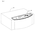
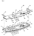
- Fig. 1 is a schematic perspective view of the multifunction device 30, and Fig. 2 is a perspective assembly drawing of an operation panel 10 for the multifunction device 30.
- the operation panel 10 is, as shown in Fig. 1, to be fitted to the multifunction device 30 provided with a plurality of predetermined functions as a scanner, a printer, a copier, and a fax.
- the operation panel 10 is formed by integrating a resin-made thick base member 12 molded by a metal mold with a resin-made plate-like thin-walled plate member 20 similarly molded by a metal mold, as shown in Fig. 2.
- the base member 12 is provided with a plurality of holes 14a to 14q for mounting all types of components used to realize the functions described above and exposed on the outer surface of the panel.
- a component mounting surface 14 of the base member 12 is a surface where the respective mounting holes 14a to 14q are opened and a surface on the side to be operated by a user.
- the component mounting surface 14 includes, on the left side of the surface, a copy button mounting hole 14a for mounting a copy button that is depressed to execute copying, a fax button mounting hole 14b for mounting a faxbutton that is depressed to send a fax, a scanner button mounting hole 14c for mounting a scanner button that is depressed to scan an image with a scanner, and a setting button mounting hole 14d for mounting a various setting button which is depressed to perform various setting operations, as well as lamp mounting holes 14e for mounting various indicator lamps, dial mounting holes 14f for mounting one-touch dials, and a speaker mounting hole 14g for mounting a speaker.
- a copy button mounting hole 14a for mounting a copy button that is depressed to execute copying
- a fax button mounting hole 14b for mounting a faxbutton that is depressed to send a fax
- a scanner button mounting hole 14c for mounting a scanner button that is depressed to scan an image with a scanner
- a setting button mounting hole 14d for mounting
- the component mounting surface 14 also includes, at about the center of the surface, a display mounting hole 14h for mounting a display that is capable of displaying various types of information.
- the component mounting surface 14 further includes, on the right side of the surface, an up, down, left, right key mounting hole 14i for mounting up, down, left, and right keys for selecting contents displayed on the display, an extension button mounting hole 14j for mounting an extension button that is depressed to extend a menu displayed on the display, a reset button mounting hole 14k for mounting a reset button that is depressed to reset set contents, a monochrome start button mounting hole 141 for mounting a monochrome start button that is depressed to instruct to start operation in monochrome, a color start button mounting hole 14m for mounting a color start button that is depressed to instruct to start operation in color, and a stop button mounting hole 14n for mounting a stop button that is depressed to instruct to stop operation, as well as a numeric keypad mounting hole 14o for mounting a numeric keypad, an abbreviation button mounting
- the component mounting surface 14 has a plurality of hook latching holes 16 that are formed along the circumference of the surface.
- components are mounted in all of the respective mounting holes 14a to 14q. Although not illustrated, these components are fixed to the rear side of the component mounting surface 14 and are exposed from the respective mounting holes 14a to 14q.
- a peripheral wall portion 18 is built so as to surround the circumference.
- the peripheral wall portion 18 plays not only a role to protect the components mounted in the respective mounting holes 14a to 14q and enhance strength of the operation panel 10 but also a role as a base when fitted to a chassis of the multifunction device 30.
- cutout grooves 19 cut out in rectangular forms are formed.
- Theplatemember 20 is formed ina size to cover the component mounting surface 14 of the base member 12, and has exposing holes 20a to 20q to expose the respective components outside at positions opposed to all mounting holes 14a to 14q. of these exposing holes 20a to 20q, the exposing holes 20f provided atpositions opposed to the lamp mounting holes 14e have lenses fitted therein, though not illustrated, and the exposing hole 20g provided at a position corresponding to the speaker mounting hole 14g is formed as a group of pores.
- the plate member 20 has fitting projections 22 to be fitted with the cutout grooves 19 on the component mounting surface 14 at both left and right sides.
- the plate member 20 also has a plurality of hooks 24 along the circumference of the rear surface, and when the plate member 20 is integrated with the base member 12, these hooks 24 are latched and held on hook latching holes 16 formed on the component mounting surface 14, Conditions before and after the hooks 24 are inserted into the hook latching holes 16 are shown in Figs. 3.
- the base member 12 is first prepared, and components are mounted in all mounting holes 14a to 14q of this base member 12.
- the plate member 20 provided with the exposing holes 20a to 20q to expose components outside at positions opposed to the mounting holes 14a to 14q in which the components have been mounted is prepared, and the plate member 20 is integrated with the base member 12 by covering the component mounting surface 14 with the plate member 20 and fitting the respective hooks 24 into the respective hook latching holes 16.
- the fitting projections 22 and 22 of the plate member 20 are fitted into the cutout grooves 19 of the component mounting surface 14. In this condition, when the fitting projections 22 and 22 are held down by holding members 28 from the upside, it becomes possible to fix the plate member 20 so as not to come off the base member 12.
- Fig. 4 is a schematic perspective view of the multifunction device 60
- Fig. 5 is a perspective assembly drawing of an operation panel 40 for the multifunction device 60.
- the operation panel 40 is, as shown in Fig. 4, to be fitted to the multifunction device 60 provided with respective functions as a scanner, a printer, and a copier, that is, the multifunction device 60 in which a facsimile function has been omitted.
- the operation panel 40 is formed by integrating a resin-made thick base member 12 molded by a metal mold with a resin-made plate-like thin-walled plate member 26 similarly molded by a metal mold, as shown in Fig. 4.
- the base member 12 is a member common to that used in the foregoing operation panel 10, here the same symbols are used for the same elements and description thereof will be omitted. However, instead of mounting components in all fitting holes 14a to 14q, components related to the facsimile function are not mounted. In other words, one-touch dial buttons, a fax button, a speaker, an abbreviation button, and a redial button are not mounted in the dial mounting holes 14f, fax button mounting hole 14b, speaker mounting hole 14g, abbreviation button mounting hole 14p, and redial button mounting hole 14q, respectively.
- the plate member 26 is the same in construction as the foregoing plate member 20 except for that the number of exposing holes is different, the same symbols are used for the same elements and description thereof will be omitted.
- the exposing holes 20a, 20c to 20e, and 20h to 20o to expose respective components outside are provided at positions opposed to the mounting holes 14a, 14c to 14e, and 14g to 14o in which the components have been mounted.
- integration of the plate member 26 with the base member 12 is the same as the integration of the plate member 20 with the base member 12, description thereof will be omitted.
- the base member 12 is first prepared, components are mounted in mounting holes 14a, 14c to 14e, and 14g to 14o of the base member 12, and other mounting holes 14b, 14f, 14p, and 14q are left vacant without mounting components therein.
- the plate member 26 provided with the exposing holes 20a, 20c to 20e, 20g to 20o to expose components outside at positions opposed to the mounting holes 14a, 14c to 14e, and 14g to 14o in which the components have been mounted is prepared, and the plate member 26 is integrated with the base member 12 by covering the component mounting surface 14 with the plate member 26 and fitting the respective hooks 24 into the respective hook latching holes 16.
- the plate member 20 provided with the exposing holes 20a to 20q at positions opposed to all mounting holes 14a to 14q is integrated with the base member 12 as in the operation panel 10
- the plate member 26 provided with the exposing holes 20a, 20c to 20e, and 20g to 20o at positions opposed to 14a, 14c to 14e, and 14g to 14o is integrated with the base member 12 as in the operation panel 40.
- the above constructions of the operation panel 10 and the operation panel 40 have the base member 12 in common, and it requires exchange of only the plate member provides to prepare the operation panel 10 and the operation panel 40. Thus, manufacturing costs of the operation panel can be kept low.
- the plate member 20 is an all component-compliant plate (optional function-compliant plate) provided with the exposing holes 20a to 20q at positions opposed to each of the mounting holes 14a and 14q, while the plate member 26 is a partial component-compliant plate (basic function-compliant plate) provided with exposing holes at positions opposed to some of the plurality of mounting holes 14a to 14q. It becomes possible to manufacture multiple types of operation panels 10 and 40 by only selecting either of these.
- the base material 12 has the cutout grooves 19 at its peripheral edges and the plate members 20 and 26 have fitting projections 22 that are fitted into the cutout grooves 19 when being integrated with the base member 12.
- the plate members 20 and 26 can be prevented from coming off from the base member 12 by holding down the plate members 20 and 26 by the holding members 28 from the upside of the fitting projections 22.
- the basic function as at least one of the functions as a scanner, a copier, and a fax, or to provide the basic function as a monochrome printing function, and the optional function, as a color printing function.
Landscapes
- Engineering & Computer Science (AREA)
- Multimedia (AREA)
- Signal Processing (AREA)
- Microelectronics & Electronic Packaging (AREA)
- Physics & Mathematics (AREA)
- General Physics & Mathematics (AREA)
- Casings For Electric Apparatus (AREA)
- Facsimiles In General (AREA)
- Accessory Devices And Overall Control Thereof (AREA)
- Electrophotography Configuration And Component (AREA)
Abstract
An operation panel 40 is prepared in the following manner. First, components are mounted in mounting holes 14a, 14c to 14e, and 14g to 14o of a base member 12, and other mounting holes 14b, 14f, 14p, and 14q are left vacant without mounting components therein. Next, a plate member 26 that is provided with exposing holes 20a, 20c to 20e, 20g to 20o to expose components outside at positions opposed to the mounting holes 14a, 14c to 14e, and 14g to 14o in which the components have been mounted and is provided with no expos'ing holes at positions opposed to vacant mounting holes 14b, 14f, 14p, and 14q is prepared. The plate member 26 is integrated with the base member 12 by covering a component mounting surface 14 with the plate member 26 and fitting respective hooks 24 into respective hook latching holes 16.
Description
- The present invention relates to an operation panel fitted to an electronic control apparatus, a manufacturing method of the same, and an electronic control apparatus.
- Conventionally, operation panels fitted to electronic control apparatuses such as printers and faxes have been known. Although such operation panels are often provided with a large number of switches, some users may use only specific switches of these. Therefore, in
Japanese Published Unexamined Patent Application No. 2003-298791 - The technique disclosed in
Japanese Published unexamined PatentApplicationNo. 2003-298791 - The present invention has been made to solve such a problem, and an object thereof is to provide an operation panel that allows manufacturing multiple types at a low cost and a manufacturing method thereof. Moreover, an object is to provide an electronic control apparatus having such an operation panel.
- In order to achieve the above-described objects, the present invention has employed the following means.
- The present invention is directed to a first operation panel that is used when operating an electronic control apparatus, and includes: a base member that has first component mounting holes capable of mounting components to be exposed on an outer surface of the panel out of components used for a setting or operation of a basic function and second component mounting holes capable of mounting components to be exposed on the outer surface of the panel out of components used for a setting or operation of an optional function added to the basic function; and a plate member that is integrated with the base member so as to cover an operating surface side of the base member and is provided with exposing holes at least at positions opposed to the first component mounting holes.
- In the first operation panel according to the present invention, thebasememberhas the first component mounting holes capable of mounting components to be exposed on an outer surface of the panel out of components used for a setting or operation of a basic function and the second component mounting holes capable of mounting components to be exposed on the outer surface of the panel out of components used for a setting or operation of an optional function added to the basic function. It is possible to mount components in both the first and second component mounting holes as well as to mount components in only the first component mounting holes. In case where components have been mounted in both first and second component mounting holes of the base member, the base member can be integrated with the plate member that is provided with exposing holes both at positions opposed to the first component mounting holes and at positions opposed to the second component mounting holes. In case where components have been mounted in only the first component mounting holes of the base member, on the other hand, the base member can be integrated with the plate member that is provided with exposing holes only at positions opposed to the first component mounting holes with the base member. As such, it is sufficient to exchange only the plate member while using the base member in common when manufacturing multiple types of operation panels, and thus manufacturing costs can be kept low.
- Here, as the "basic function" and the "optional function, it may be possible to provide the basic function as a print function, and the optional function as at least one of a copy function, a scanner function, and a facsimile function, otherwise to provide the basic function as a print function, a copy function, and a scanner function, and the optional function as a facsimile function, or provide the basic function as a monochrome printing function, and the optional function as a color printing function.
- In the first operation panel of the invention, the plate member may be selected from a basic function-compliant plate member having exposing holes only at positions opposed to the first component mounting holes and an optional function-compliant plate member having exposing holes both at positions opposed to the first component mounting holes and at positions opposed to the second component mounting holes. The selection either the basic function-compliant plate or the optional function-compliant plate allows for manufacture of multiple types of operation panels.
- The present invention is also directed to a second operation panel that is used when operating an electronic control apparatus, and includes: a base member that has a component mounting surface provided with a plurality of mounting holes for mounting all types of components, where components have been mounted in some of the plurality of mounting holes; and a plate member that is integrated with the base member so as to cover the component mounting surface and is provided with exposing holes to expose the components outside at positions opposed to mounting holes in which the components have been mounted.
- In the second operation panel according to the present invention, the base member has the plurality of mounting holes for mounting all types of components are. It is possible to mount all types of components as well as tomount only some of all types of components. In case where components have been mounted in all mounting holes of the base member, the base member is integrated with the plate member that is provided with exposingholes atpositions opposed to all mounting holes. In case where components have been mounted in some of the mounting holes of the base member, on the other hand, the base member is integrated with the plate member that is provided with exposing holes at positions opposed to some of the component mounting holes. As such, it is sufficient to exchange only the plate member while using the base member in common when manufacturing multiple types of operation panels, and thus manufacturing costs can be kept low.
- Here, the "all types of components" mean all types of components that are used to realize a plurality of predetermined functions and exposed on the outer surface of the panel. Moreover, the "component mounting surface" means a surface of the base member where a plurality of mounting holes for mounting components are opened.
- In the second operation panel of the invention, the plate member may be selected from an all component-compliant plate provided with the exposing holes at positions opposed to each of the mounting holes andapartial component-compliant plate provided with the exposing holes at positions opposed to some of the plurality of mounting holes. The selection either the basic function-compliant plate or the optional function-compliant plate allows for manufacture of multiple types of operation panels.
- In the first and second operation panels of the invention, the plate member may be formed in a plate-like shape, and the base member may be thicker than the plate member. In this case, it is relatively easy even to prepare multiple types since the plate member has a plate-like shape, whereas since the base member is thick, it is highly significant to provide it as a common component as the cost easily rises when multiple types are prepared. This is more prominent in the case of molding by a metal mold.
- In the first and second operation panels of the invention, the base member may have cutout grooves at peripheral portions, and the plate member may have fitting projections that are fitted into the cutout grooves when being integrated with the base member. This structure prevents the plate member from coming off from the base member by holding down the plate member by holding members from the upside of the fitting projections when the operation panel of invention is fitted to an electronic control apparatus.
- In the first and second operation panels of the invention, information concerning components exposed from the exposing holes may be printed in the vicinity of the exposing holes of the plate member. Thus, a user is allowed to easily know the information concerning the exposed components without depending on an instruction manual or the like. When the plate member is formed in a plate-like shape, such printing of information can be easily carried out. Here, the information concerning components is information that represents, for example, names and functions of components, and it may be letters as well as symbols/graphics that mean something. In the case of letters, it may be carried out in various languages.
- The present invention is also directed to an electronic control apparatus including any of theabove-describedoperationpanels of the invention. As for the operation panel of the invention, it is sufficient to exchange only the plate member while using the base member in common, so as to manufacture multiple types of operation panels, keeping manufacturing costs low. As for the electronic control apparatus employing the operation panel, it is accordingly possible to keep manufacturing cost low, and thus the cost of the electronic control apparatus as a whole can be lowered. The electronic control apparatus, though not particularly limited, may be a printer, a fax, a copier, a scanner, and a multifunction device provided with functions of two or more of these.
- The present invention is further directed to a first manufacturing method for an operation panel to be fitted to a chassis of an electronic control apparatus. The first manufacturing method includes the steps of: (a) preparing a base member that has first component mounting holes capable of mounting components to be exposed on an outer surface of the panel out of components used for a setting or operation of a basic function and second component mounting holes capable of mounting components to be exposed on the outer surface of the panel out of components used for a setting or operation of an optional function added to the basic function, and mounting components in only the first component mounting holes or mounting components in both the first and second component mounting holes; and (b) selecting either plate member according to the components mounted in the step (a) of a basic function-compliant plate member having exposing holes only at positions opposed to the first component mounting holes and an optional functian-compliant plate member having exposing holes both at positions opposed to the first component mounting holes and at the positions opposed to the second component mounting holes, and covering an operating surface side of the base member with the selected plate member so as to integrate the plate member with the base member.
- The first manufacturing method for an operation panel of the invention prepares the base member that has the first component mounting holes capable of mounting components to be exposed on an outer surface of the panel out of components used for a setting or operation of a basic function and the second component mounting holes capable of mounting components to be exposed on the outer surface of the panel out of components used for a setting or operation of an optional function added to the basic function. It is possible to mount components in both the first and second component mounting holes as well as to mount components in only the first component mounting holes. In case where components have been mounted in both first and second component mounting holes of the base member, the base member can be integrated with the plate member that is provided with exposing holes both at positions opposed to the first component mounting holes and at positions opposed to the second component mounting holes. In case where components have been mounted in only the first component mounting holes of the base member, on the other hand, the base member can be integrated with the plate member that is provided with exposing holes only at positions opposed to the first component mounting holes with the base member. As such, it is sufficient to exchange only the plate member while using the base member in common when manufacturing multiple types of operation panels, and thus manufacturing costs can be kept low.
- The present invention is further directed to a second manufacturing method for an operation panel to be fitted to a chassis of an electronic control apparatus. The second manufacturing method includes the steps of: (a) preparing a base member that has a component mounting surf ace provided wi th a plural ity of mounting holes f or mounting all types of components, and mounting components in all or some of the plurality of mounting holes; and (b) preparing a plate member that is provided with exposing holes to expose the components outside at positions opposed to mounting holes in which the components have been mounted and is provided with no exposing holes at positions opposed to vacant mounting holes, and covering the component mounting surface with the plate member so as to integrate the plate member with the base member.
- The second manufacturing method for an operation panel of the invention prepares the base member that has the plurality of mounting holes for mounting all types of components are. It is possible to mount all types of components as well as to mount only some of all types of components. In case where components have been mounted in all mounting holes of the base member, the base member is integrated with the plate member that is provided with exposing holes at positions opposed to all mounting holes. In case where components have been mounted in some of the mounting holes of the base member, on the other hand, the base member is integrated with the plate member that is provided with exposing holes at positions opposed to some of the component , mounting holes. As such, it is sufficient to exchange only the plate member while using the base member in common when manufacturing multiple types of operation panels, and thus manufacturing costs can be kept low.
-
- Fig. 1 is a schematic perspective view of a full-featured multifunction device.
- Fig. 2 is a perspective assembly drawing of an operation panel for a full-featured multifunction device.
- Figs. 3 are sectional views showing conditions before and after hooks are inserted into hook latching holes.
- Fig. 4 is a schematic perspective view of a multifunction device with a simplified function.
- Fig. 5 is a perspective assembly drawing of an operation panel for a multifunction device with a simplified function.
- First, a full-featured
multifunction device 30 will be described. Fig. 1 is a schematic perspective view of themultifunction device 30, and Fig. 2 is a perspective assembly drawing of anoperation panel 10 for themultifunction device 30. Theoperation panel 10 is, as shown in Fig. 1, to be fitted to themultifunction device 30 provided with a plurality of predetermined functions as a scanner, a printer, a copier, and a fax. Theoperation panel 10 is formed by integrating a resin-madethick base member 12 molded by a metal mold with a resin-made plate-like thin-walled plate member 20 similarly molded by a metal mold, as shown in Fig. 2. - The
base member 12 is provided with a plurality ofholes 14a to 14q for mounting all types of components used to realize the functions described above and exposed on the outer surface of the panel. Acomponent mounting surface 14 of thebase member 12 is a surface where the respective mountingholes 14a to 14q are opened and a surface on the side to be operated by a user. Thecomponent mounting surface 14 includes, on the left side of the surface, a copybutton mounting hole 14a for mounting a copy button that is depressed to execute copying, a faxbutton mounting hole 14b for mounting a faxbutton that is depressed to send a fax, a scannerbutton mounting hole 14c for mounting a scanner button that is depressed to scan an image with a scanner, and a settingbutton mounting hole 14d for mounting a various setting button which is depressed to perform various setting operations, as well aslamp mounting holes 14e for mounting various indicator lamps, dial mountingholes 14f for mounting one-touch dials, and aspeaker mounting hole 14g for mounting a speaker. Thecomponent mounting surface 14 also includes, at about the center of the surface, adisplay mounting hole 14h for mounting a display that is capable of displaying various types of information. Thecomponent mounting surface 14 further includes, on the right side of the surface, an up, down, left, rightkey mounting hole 14i for mounting up, down, left, and right keys for selecting contents displayed on the display, an extensionbutton mounting hole 14j for mounting an extension button that is depressed to extend a menu displayed on the display, a resetbutton mounting hole 14k for mounting a reset button that is depressed to reset set contents, a monochrome startbutton mounting hole 141 for mounting a monochrome start button that is depressed to instruct to start operation in monochrome, a color startbutton mounting hole 14m for mounting a color start button that is depressed to instruct to start operation in color, and a stop button mounting hole 14n for mounting a stop button that is depressed to instruct to stop operation, as well as a numeric keypad mounting hole 14o for mounting a numeric keypad, an abbreviationbutton mounting hole 14p for mounting an abbreviation button that is depressed to call up abbreviated dialing numbers of the fax, and a redialbutton mounting hole 14q for mounting a redial button that is depressed to instruct the fax to redial. Thecomponent mounting surface 14 has a plurality ofhook latching holes 16 that are formed along the circumference of the surface. Here, components are mounted in all of the respective mountingholes 14a to 14q. Although not illustrated, these components are fixed to the rear side of thecomponent mounting surface 14 and are exposed from the respective mountingholes 14a to 14q. - On the rear side of the component mounting surface of the
base member 12, aperipheral wall portion 18 is built so as to surround the circumference. Theperipheral wall portion 18 plays not only a role to protect the components mounted in the respective mountingholes 14a to 14q and enhance strength of theoperation panel 10 but also a role as a base when fitted to a chassis of themultifunction device 30. In addition, at both left and right sides of thecomponent mounting surface 14,cutout grooves 19 cut out in rectangular forms are formed. -
Theplatemember 20 is formed ina size to cover thecomponent mounting surface 14 of thebase member 12, and has exposingholes 20a to 20q to expose the respective components outside at positions opposed to all mountingholes 14a to 14q. of these exposingholes 20a to 20q, the exposingholes 20f provided atpositions opposed to thelamp mounting holes 14e have lenses fitted therein, though not illustrated, and the exposinghole 20g provided at a position corresponding to thespeaker mounting hole 14g is formed as a group of pores. Theplate member 20 hasfitting projections 22 to be fitted with thecutout grooves 19 on thecomponent mounting surface 14 at both left and right sides. Theplate member 20 also has a plurality ofhooks 24 along the circumference of the rear surface, and when theplate member 20 is integrated with thebase member 12, thesehooks 24 are latched and held onhook latching holes 16 formed on thecomponent mounting surface 14, Conditions before and after thehooks 24 are inserted into thehook latching holes 16 are shown in Figs. 3. - Next, procedures for assembling the
operation panel 10 will be described. Thebase member 12 is first prepared, and components are mounted in all mountingholes 14a to 14q of thisbase member 12. Next, theplate member 20 provided with the exposingholes 20a to 20q to expose components outside at positions opposed to the mountingholes 14a to 14q in which the components have been mounted is prepared, and theplate member 20 is integrated with thebase member 12 by covering thecomponent mounting surface 14 with theplate member 20 and fitting therespective hooks 24 into the respective hook latching holes 16. When theplate member 20 is integrated with thebase member 12, thefitting projections plate member 20 are fitted into thecutout grooves 19 of thecomponent mounting surface 14. In this condition, when thefitting projections members 28 from the upside, it becomes possible to fix theplate member 20 so as not to come off thebase member 12. - Next, a
multifunction device 60 with a simplified function will be described. Fig. 4 is a schematic perspective view of themultifunction device 60, and Fig. 5 is a perspective assembly drawing of anoperation panel 40 for themultifunction device 60. Theoperation panel 40 is, as shown in Fig. 4, to be fitted to themultifunction device 60 provided with respective functions as a scanner, a printer, and a copier, that is, themultifunction device 60 in which a facsimile function has been omitted. Theoperation panel 40 is formed by integrating a resin-madethick base member 12 molded by a metal mold with a resin-made plate-like thin-walled plate member 26 similarly molded by a metal mold, as shown in Fig. 4. - Since the
base member 12 is a member common to that used in the foregoingoperation panel 10, here the same symbols are used for the same elements and description thereof will be omitted. However, instead of mounting components in allfitting holes 14a to 14q, components related to the facsimile function are not mounted. In other words, one-touch dial buttons, a fax button, a speaker, an abbreviation button, and a redial button are not mounted in thedial mounting holes 14f, faxbutton mounting hole 14b,speaker mounting hole 14g, abbreviationbutton mounting hole 14p, and redialbutton mounting hole 14q, respectively. - Since the
plate member 26 is the same in construction as the foregoingplate member 20 except for that the number of exposing holes is different, the same symbols are used for the same elements and description thereof will be omitted. In theplate member 26, the exposingholes holes plate member 26 with thebase member 12 is the same as the integration of theplate member 20 with thebase member 12, description thereof will be omitted. - Next, procedures for assembling the
operation panel 40 will be described. Thebase member 12 is first prepared, components are mounted in mountingholes base member 12, and other mountingholes plate member 26 provided with the exposingholes holes plate member 26 is integrated with thebase member 12 by covering thecomponent mounting surface 14 with theplate member 26 and fitting therespective hooks 24 into the respective hook latching holes 16. When theplate member 26 is integrated with thebase member 12, thefitting projections plate member 20 are fitted into thecutout grooves component mounting surface 14. In this condition, when thefitting projections members 28 from the upside, it becomes possible to fix theplate member 26 so as not to come off the base member 12: - According to the embodiment described above in detail, when components have been mounted in all mounting
holes 14a to 14q of thebase member 12, theplate member 20 provided with the exposingholes 20a to 20q at positions opposed to all mountingholes 14a to 14q is integrated with thebase member 12 as in theoperation panel 10, and when components have been mounted in some mountingholes base member 12, theplate member 26 provided with the exposingholes base member 12 as in theoperation panel 40. The above constructions of theoperation panel 10 and theoperation panel 40 have thebase member 12 in common, and it requires exchange of only the plate member provides to prepare theoperation panel 10 and theoperation panel 40. Thus, manufacturing costs of the operation panel can be kept low. - The
plate member 20 is an all component-compliant plate (optional function-compliant plate) provided with the exposingholes 20a to 20q at positions opposed to each of the mountingholes plate member 26 is a partial component-compliant plate (basic function-compliant plate) provided with exposing holes at positions opposed to some of the plurality of mountingholes 14a to 14q. It becomes possible to manufacture multiple types ofoperation panels - It is relatively easy to manufacture multiple types of plate members since the
plate members base member 12, which is thick. It is significant to provide thebase member 12 as a common component. This is more prominent in the case of molding by a metal mold. - The
base material 12 has thecutout grooves 19 at its peripheral edges and theplate members fitting projections 22 that are fitted into thecutout grooves 19 when being integrated with thebase member 12. When theoperation panels multifunction devices plate members base member 12 by holding down theplate members members 28 from the upside of thefitting projections 22. - The above embodiment is be considered in all aspects as illustrative and not restrictive. There may be many modifications, changes, and alterations without departing from the scope or spirit of the main characteristics of the present invention.
- In the above embodiment, a description has been given of the
operation panel 10 used for themultifunction device 30 and theoperation panel 40 used for themultifunction device 60. It may also be possible to manufacture of operation panels of single-function printers, faxes, and scanners by using thebase member 12 as a common component and plate members as different components, and integrating both. - It may be possible to print names or icons of buttons and the like exposed from the respective exposing holes, in the vicinity of the exposing holes of the
plate members plate members base member 12. Here, a language suitable for the country in which the device is soled may be employed for the names. - With respect to the
plate members - In the above embodiment, a description has been given on the assumption that the three functions as a scanner, a printer, and a copier on the
multifunction device 60 are equivalent to the basic function and the facsimile function on themultifunction device 30 is equivalent to the optional function. It may be possible to provide the basic function as at least one of the functions as a scanner, a copier, and a fax, or to provide the basic function as a monochrome printing function, and the optional function, as a color printing function. - The present invention claims the benefit of priority from
Japanese Patent Application No. 2005-071973 filed on March 14, 2005 Japanese Patent Application No. 2006-000812 filed on January 5, 2006
Claims (11)
- An operation panel that is used when operating an electronic control apparatus, comprising:a base member that has first component mounting holes capable of mounting components to be exposed on an outer surface of the panel out of components used for a setting or operation of a basic function and second component mounting holes capable of mounting components to be exposed on the outer surface of the panel out of components used for a setting or operation of an optional function added to the basic function; anda plate member that is integrated with the base member so as to cover an operating surface side of the base member and is provided with exposing holes at least at positions opposed to the first component mounting holes.
- The operation panel according to Claim 1, wherein the plate member is selected from a basic function-compliant plate member having exposing holes only at positions opposed to the first component mounting holes and an optional function-compliant plate member having exposing holes both at positions opposed to the first component mounting holes and at positions opposed to the second component mounting holes.
- An operation panel that is used when operating an electronic control apparatus, comprising:a base member that has a component mounting surface provided with a plurality of mounting holes for mounting all types of components, where components have been mounted in some of the plurality of mounting holes; anda plate member that is integrated with the base member so as to cover the component mounting surface and is provided with exposing holes to expose the components outside at positions opposed to mounting holes in which the components have been mounted.
- The operation panel according to Claim 3, wherein the plate member is selected from an all component-compliant plate provided with the exposing holes at positions opposed to each of the mounting holes and a partial component-compliant plate provided with the exposing holes at positions opposed to some of the plurality of mounting holes.
- The operation panel according to any of Claims 1 to 4, wherein the plate member is formed in a plate-like shape, and the base member is thicker than the plate member.
- The operation panel according to any of Claims 1 to 5, wherein the plate member and the base member are mold products.
- The operation panel according to any of Claims 1 to 6, wherein the base member has cutout grooves at peripheral portion, and the plate member has fitting projections that are fitted into the cutout grooves when being integrated with the base member.
- The operation panel according to any of Claims 1 to 7, wherein information concerning components exposed from the exposing holes is printed in the vicinity of the exposing holes of the plate member.
- An electronic control apparatus comprising the operation panel according to any of Claims 1 to 8.
- A manufacturing method for an operation panel to be fitted to a chassis of an electronic control apparatus, comprising the steps of:(a) preparing a base member that has first component mounting holes capable of mounting components to be exposed on an outer surface of the panel out of components used for a setting or operation of a basic function and second component mounting holes capable of mounting components to be exposed on the outer surface of the panel out of components used for a setting or operation of an optional function added to the basic function, and mounting components in only the first component mounting holes or mounting components in both the first and second component mounting holes; and(b) selecting either plate member according to the components mounted in the step (a) of a basic function-compliant plate member having exposing holes only at positions opposed to the first component mounting holes and an optional function-compliant plate member having exposing holes both at positions opposed to the first component mounting holes and at the positions opposed to the second component mounting holes, and covering an operating surface side of the base member with the selected plate member so as to integrate the plate member with the base member.
- A manufacturing method for an operation panel to be fitted to a chassis of an electronic control apparatus, comprising the steps of:(a) preparing a base member that has a component mounting surface provided with a plurality of mounting holes for mounting all types of components, and mounting components in all or some of the plurality of mounting holes; and(b) preparing a plate member that is provided with exposing holes to expose the components outside at positions opposed to mounting holes in which the components have been mounted and is provided with no exposing holes at positions opposed to vacant mounting holes, and covering the component mounting surface with the plate member so as to integrate the plate member with the base member.
Applications Claiming Priority (2)
| Application Number | Priority Date | Filing Date | Title |
|---|---|---|---|
| JP2005071793 | 2005-03-14 | ||
| JP2006000812A JP2006295885A (en) | 2005-03-14 | 2006-01-05 | Operation panel, manufacturing method thereof, and electronic control device |
Publications (1)
| Publication Number | Publication Date |
|---|---|
| EP1703335A1 true EP1703335A1 (en) | 2006-09-20 |
Family
ID=36424058
Family Applications (1)
| Application Number | Title | Priority Date | Filing Date |
|---|---|---|---|
| EP06005184A Withdrawn EP1703335A1 (en) | 2005-03-14 | 2006-03-14 | Operation panel, manufacturing method thereof, and electronic control apparatus |
Country Status (3)
| Country | Link |
|---|---|
| US (1) | US20060226745A1 (en) |
| EP (1) | EP1703335A1 (en) |
| JP (1) | JP2006295885A (en) |
Cited By (1)
| Publication number | Priority date | Publication date | Assignee | Title |
|---|---|---|---|---|
| DE102014116397A1 (en) * | 2014-11-11 | 2016-05-12 | Jungheinrich Aktiengesellschaft | System with switch unit and switch panel |
Families Citing this family (7)
| Publication number | Priority date | Publication date | Assignee | Title |
|---|---|---|---|---|
| WO2008053906A1 (en) | 2006-10-31 | 2008-05-08 | Canon Kabushiki Kaisha | Electrophotographic photosensitive body, method for producing electrophotographic photosensitive body, process cartridge, and electrophotographic device |
| JP5544347B2 (en) * | 2011-10-27 | 2014-07-09 | 京セラドキュメントソリューションズ株式会社 | Operation unit mounting structure and image forming apparatus |
| JP2015161914A (en) * | 2014-02-28 | 2015-09-07 | 株式会社リコー | image forming apparatus |
| KR101830372B1 (en) * | 2015-09-01 | 2018-02-20 | 삼성전자주식회사 | Refrigerator |
| JP6042016B2 (en) * | 2016-06-10 | 2016-12-14 | シャープ株式会社 | Image forming apparatus |
| US10666823B2 (en) | 2016-07-01 | 2020-05-26 | Hewlett-Packard Development Company, L.P. | Modular dashboard of a printing device with cut-outs for user controls |
| JP7281878B2 (en) * | 2018-07-13 | 2023-05-26 | 能美防災株式会社 | Decorative panel and method for manufacturing decorative panel |
Citations (5)
| Publication number | Priority date | Publication date | Assignee | Title |
|---|---|---|---|---|
| US4092527A (en) * | 1977-01-31 | 1978-05-30 | Texas Instruments Incorporated | Calculator with interchangeable keyset |
| DE4024523A1 (en) * | 1990-08-02 | 1992-02-13 | Slc Informationssysteme Gmbh | Control panel for office copier - has respective switch function keys selectively removed from respective panel plate opening |
| JPH11306903A (en) * | 1998-04-23 | 1999-11-05 | Canon Inc | control panel |
| US6111207A (en) * | 1999-06-30 | 2000-08-29 | Hewlett-Packard Company | Kit for multi-configurable control panel design for office equipment |
| JP2003298791A (en) * | 2002-03-29 | 2003-10-17 | Murata Mach Ltd | Mask cover for console panel and communication terminal device having it |
Family Cites Families (4)
| Publication number | Priority date | Publication date | Assignee | Title |
|---|---|---|---|---|
| US4119839A (en) * | 1976-11-30 | 1978-10-10 | W & G Instruments, Inc. | Keyboard mask for general-purpose calculator |
| US6130389A (en) * | 1999-05-26 | 2000-10-10 | Tower Manufacturing Corporation | Housing for an electric switch |
| JP2004522309A (en) * | 2001-06-22 | 2004-07-22 | エルジー エレクトロニクス インコーポレイティド | Control panel assembly for home appliance and method of manufacturing the same |
| US6770824B1 (en) * | 2003-10-22 | 2004-08-03 | Hewlett-Packard Development Company, L.P. | Buckling key caps and method |
-
2006
- 2006-01-05 JP JP2006000812A patent/JP2006295885A/en not_active Withdrawn
- 2006-03-14 EP EP06005184A patent/EP1703335A1/en not_active Withdrawn
- 2006-03-14 US US11/374,081 patent/US20060226745A1/en not_active Abandoned
Patent Citations (5)
| Publication number | Priority date | Publication date | Assignee | Title |
|---|---|---|---|---|
| US4092527A (en) * | 1977-01-31 | 1978-05-30 | Texas Instruments Incorporated | Calculator with interchangeable keyset |
| DE4024523A1 (en) * | 1990-08-02 | 1992-02-13 | Slc Informationssysteme Gmbh | Control panel for office copier - has respective switch function keys selectively removed from respective panel plate opening |
| JPH11306903A (en) * | 1998-04-23 | 1999-11-05 | Canon Inc | control panel |
| US6111207A (en) * | 1999-06-30 | 2000-08-29 | Hewlett-Packard Company | Kit for multi-configurable control panel design for office equipment |
| JP2003298791A (en) * | 2002-03-29 | 2003-10-17 | Murata Mach Ltd | Mask cover for console panel and communication terminal device having it |
Non-Patent Citations (2)
| Title |
|---|
| PATENT ABSTRACTS OF JAPAN vol. 2000, no. 02 29 February 2000 (2000-02-29) * |
| PATENT ABSTRACTS OF JAPAN vol. 2003, no. 12 5 December 2003 (2003-12-05) * |
Cited By (1)
| Publication number | Priority date | Publication date | Assignee | Title |
|---|---|---|---|---|
| DE102014116397A1 (en) * | 2014-11-11 | 2016-05-12 | Jungheinrich Aktiengesellschaft | System with switch unit and switch panel |
Also Published As
| Publication number | Publication date |
|---|---|
| JP2006295885A (en) | 2006-10-26 |
| US20060226745A1 (en) | 2006-10-12 |
Similar Documents
| Publication | Publication Date | Title |
|---|---|---|
| EP1703335A1 (en) | Operation panel, manufacturing method thereof, and electronic control apparatus | |
| US20040145764A1 (en) | Image displaying device and image forming device | |
| US8869067B2 (en) | Operating device, control panel, and image forming apparatus including same | |
| JP2005101796A (en) | Communication terminal device | |
| JPH09321923A (en) | Multi-function image forming device | |
| JP3832370B2 (en) | Mask cover for operation panel and communication terminal device having the same | |
| JP3726798B2 (en) | Communication terminal device | |
| KR20050074810A (en) | Apparatus for scanning a document having excessive scan size and method thereof for use in an office machine | |
| JP4251162B2 (en) | Image forming apparatus | |
| JP4650621B2 (en) | Image processing apparatus and image processing program | |
| JP4026523B2 (en) | Facsimile device | |
| JP2007006287A (en) | Image forming apparatus | |
| US20050072659A1 (en) | Mutiple-function products with user-friendly operation interface | |
| JP2001238029A (en) | Image forming device | |
| JP2004297325A (en) | Information transmission device | |
| JP2000151790A (en) | Communication terminal with single operation dial key | |
| JPH09204256A (en) | Facsimile multifunction device | |
| EP0316883A2 (en) | Facsimile device | |
| JP2007180962A (en) | Portable terminal device, cover panel, and function control method and program | |
| JP2006245900A (en) | Facsimile machine | |
| KR100222975B1 (en) | Multi Division / Copy Printing Method | |
| KR100599140B1 (en) | How to change and register link relationship between one-touch key and memory in multifunction device | |
| JP2008155373A (en) | Image processing apparatus and image processing method | |
| JPH09282966A (en) | Operation panel | |
| JPH0528166U (en) | Facsimile device with one-touch function key |
Legal Events
| Date | Code | Title | Description |
|---|---|---|---|
| PUAI | Public reference made under article 153(3) epc to a published international application that has entered the european phase |
Free format text: ORIGINAL CODE: 0009012 |
|
| AK | Designated contracting states |
Kind code of ref document: A1 Designated state(s): AT BE BG CH CY CZ DE DK EE ES FI FR GB GR HU IE IS IT LI LT LU LV MC NL PL PT RO SE SI SK TR |
|
| AX | Request for extension of the european patent |
Extension state: AL BA HR MK YU |
|
| STAA | Information on the status of an ep patent application or granted ep patent |
Free format text: STATUS: THE APPLICATION HAS BEEN WITHDRAWN |
|
| 18W | Application withdrawn |
Effective date: 20070416 |