EP1703250A1 - Collision detection apparatus for vehicle - Google Patents
Collision detection apparatus for vehicle Download PDFInfo
- Publication number
- EP1703250A1 EP1703250A1 EP06004873A EP06004873A EP1703250A1 EP 1703250 A1 EP1703250 A1 EP 1703250A1 EP 06004873 A EP06004873 A EP 06004873A EP 06004873 A EP06004873 A EP 06004873A EP 1703250 A1 EP1703250 A1 EP 1703250A1
- Authority
- EP
- European Patent Office
- Prior art keywords
- optical fiber
- light
- end portion
- light emitting
- disposed
- Prior art date
- Legal status (The legal status is an assumption and is not a legal conclusion. Google has not performed a legal analysis and makes no representation as to the accuracy of the status listed.)
- Granted
Links
- 238000001514 detection method Methods 0.000 title claims abstract description 31
- 239000013307 optical fiber Substances 0.000 claims abstract description 129
- 230000004048 modification Effects 0.000 description 10
- 238000012986 modification Methods 0.000 description 10
- 238000009434 installation Methods 0.000 description 4
- 239000006096 absorbing agent Substances 0.000 description 3
- 230000001133 acceleration Effects 0.000 description 3
- 230000003287 optical effect Effects 0.000 description 2
- 230000002787 reinforcement Effects 0.000 description 2
- 239000000969 carrier Substances 0.000 description 1
- 239000011521 glass Substances 0.000 description 1
- 239000003365 glass fiber Substances 0.000 description 1
- 238000004519 manufacturing process Methods 0.000 description 1
- 239000004033 plastic Substances 0.000 description 1
Images


Classifications
-
- B—PERFORMING OPERATIONS; TRANSPORTING
- B60—VEHICLES IN GENERAL
- B60R—VEHICLES, VEHICLE FITTINGS, OR VEHICLE PARTS, NOT OTHERWISE PROVIDED FOR
- B60R21/00—Arrangements or fittings on vehicles for protecting or preventing injuries to occupants or pedestrians in case of accidents or other traffic risks
- B60R21/01—Electrical circuits for triggering passive safety arrangements, e.g. airbags, safety belt tighteners, in case of vehicle accidents or impending vehicle accidents
- B60R21/013—Electrical circuits for triggering passive safety arrangements, e.g. airbags, safety belt tighteners, in case of vehicle accidents or impending vehicle accidents including means for detecting collisions, impending collisions or roll-over
- B60R21/0136—Electrical circuits for triggering passive safety arrangements, e.g. airbags, safety belt tighteners, in case of vehicle accidents or impending vehicle accidents including means for detecting collisions, impending collisions or roll-over responsive to actual contact with an obstacle, e.g. to vehicle deformation, bumper displacement or bumper velocity relative to the vehicle
-
- B—PERFORMING OPERATIONS; TRANSPORTING
- B60—VEHICLES IN GENERAL
- B60R—VEHICLES, VEHICLE FITTINGS, OR VEHICLE PARTS, NOT OTHERWISE PROVIDED FOR
- B60R19/00—Wheel guards; Radiator guards, e.g. grilles; Obstruction removers; Fittings damping bouncing force in collisions
- B60R19/02—Bumpers, i.e. impact receiving or absorbing members for protecting vehicles or fending off blows from other vehicles or objects
- B60R19/48—Bumpers, i.e. impact receiving or absorbing members for protecting vehicles or fending off blows from other vehicles or objects combined with, or convertible into, other devices or objects, e.g. bumpers combined with road brushes, bumpers convertible into beds
- B60R19/483—Bumpers, i.e. impact receiving or absorbing members for protecting vehicles or fending off blows from other vehicles or objects combined with, or convertible into, other devices or objects, e.g. bumpers combined with road brushes, bumpers convertible into beds with obstacle sensors of electric or electronic type
-
- B—PERFORMING OPERATIONS; TRANSPORTING
- B60—VEHICLES IN GENERAL
- B60R—VEHICLES, VEHICLE FITTINGS, OR VEHICLE PARTS, NOT OTHERWISE PROVIDED FOR
- B60R21/00—Arrangements or fittings on vehicles for protecting or preventing injuries to occupants or pedestrians in case of accidents or other traffic risks
- B60R21/01—Electrical circuits for triggering passive safety arrangements, e.g. airbags, safety belt tighteners, in case of vehicle accidents or impending vehicle accidents
- B60R2021/0104—Communication circuits for data transmission
- B60R2021/01081—Transmission medium
- B60R2021/01095—Transmission medium optical
Definitions
- An air bag apparatus inflates an airbag at the time of collision of a vehicle, thereby preventing the occupant from being hit against, for example, an instrument panel.
- various types of collision detection apparatus having, for example, an acceleration sensor or an optical fiber sensor have been developed.
- the acceleration sensor detects a collision based on a sudden drop in acceleration at the time of the collision
- the optical fiber sensor detects the collision based on a sudden drop in the amount of received light at the time of the collision.
- an optical fiber 102 is installed along a front bumper 100 of a vehicle.
- the optical fiber 102 has one end portion provided with a light emitting element 104 and the other end portion provided with a light receiving element 106.
- the optical fiber 102 corresponding to the collided portion is damaged so that light leaks out.
- the collision is detected based on a fact that the amount of light received by the light receiving element 106 is reduced with respect to the amount of light emitted by the light emitting element 104.
- the light emitting element 104 and the light receiving element 106 are disposed on one end and the other end of the optical fiber 102, respectively. Therefore, a wire and a connector (not shown) for the light emitting element 104 need to be arranged separately from those for the light receiving element 106, thereby increasing cost. Further, such a wiring layout restricts layouts of other devices and components.
- a collision detection apparatus having a light emitting element for emitting light into an optical fiber and a light receiving element for receiving light emitted out of the optical fiber.
- the light emitting element and the light receiving element are made as compact as possible.
- a collision detection apparatus includes an optical fiber installed along a predetermined portion of a vehicle, a light emitting element disposed on a side of a first end portion of the optical fiber to emit light into the first end portion, a reversing member disposed on a side of a second end portion of the optical fiber to reverse direction of travel of light exiting from the second end portion to introduce the exiting light into the second end portion, and a light receiving element disposed on the side of the first end portion of the optical fiber to receive light emitted out of the first end portion.
- one optical fiber is installed, and the light emitting element and the light receiving element are disposed on the one end portion of the optical fiber, i.e., together on a predetermined portion of the vehicle. Consequently, the number of parts such as a wire and a connector are significantly reduced compared to the conventional collision detection apparatus. Accordingly, width and length of an installation area for the collision detection apparatus can be reduced. Further, by the way of emission of light and an adoption of a light path switching member, light is smoothly transferred between the light emitting element and the optical fiber, and between the light receiving element and the optical fiber, in spite of the fact that one optical fiber is installed.
- the light emitting element emits light in a light emitting direction perpendicular to a length direction of the optical fiber, and the light receiving element receives light in a light receiving direction that is parallel to the length direction of the optical fiber.
- a light path switching member can be provided for changing a light path between when the light emitting element emits the light and when the light emitting element emits no light.
- the switching member can be disposed between the light emitting element and the right receiving element.
- the light path switching member is a one-way mirror for reflecting the light emitted by the light emitting element and for passing the light emitted out of the first end portion of the optical fiber into the light receiving element.
- the light emitting element can emit intermittent light or continuous light.
- the optical fiber can be provided with a collision absorbing member disposed around the optical fiber to absorb a load applied to the optical fiber.
- the collision detection apparatus can include first and second optical fibers arranged side by side along a predetermined portion of the vehicle, a light emitting element disposed on a side of a first end portion of the first optical fiber to emit light into the first end portion of the first optical fiber, a reversing member for reversing direction of light exiting from a second end portion of the first optical fiber to introduce the exiting light into a second end portion of the second optical fiber, and a light receiving element disposed on a side of a first end portion of the second optical fiber to receive light emitted out of the first end portion of the second optical fiber.
- the light emitting element and the light receiving element are disposed on the same side of the first and second optical fibers, i.e., together on a predetermined portion of the vehicle. Consequently, the number of the parts such as the wire and the connector is reduced about by half compared to the conventional collision detection apparatus. Accordingly, the width and length of the installation area for the collision detection apparatus can be reduced. Light travels in fixed directions inside the first optical fiber and the second optical fiber, respectively. Therefore, the light path switching member is unnecessary.
- reversing member may be a reflection mirror, arranged approximately in a V-shape, between the second end portion of the first optical fiber and the second end portion of the second optical fiber.
- the reversing member may be a light conductive member disposed from the second end portion of the first optical fiber to the second end portion of the second optical fiber.
- a collision detection apparatus of an embodiment will now be described with reference to FIGS. 1 to 4B.
- a bumper absorber 12 is disposed on a front edge side of a front portion 10 of a vehicle to extend in a width direction of the vehicle (top-bottom direction of FIG. 1).
- a bumper reinforcement 14 is disposed behind the bumper absorber 12.
- An optical fiber cable 20 is installed in a space between the bumper absorber 12 and the bumper reinforcement 14 to extend in the width direction of the vehicle.
- the optical fiber cable 20 is installed along a predetermined portion, i.e., the front portion 10 of the vehicle.
- the predetermined portion may be a side portion or an edge portion (corner portion) that is easy to be damaged by collision.
- the optical fiber cable 20 be installed along the predetermined portion to be straightened, the optical fiber may be bent.
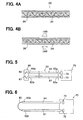
- the optical fiber cable 20 includes a flexible cylindrical casing (bendable member) 24 having therein a hollow portion and an optical fiber 26 disposed in the hollow portion.
- the optical fiber 26 may be made of glass fiber and have an optical fiber core and a clad (not shown).
- a circuit box 30 is disposed at one end portion 21 (bottom end of FIG. 1) of the optical fiber cable 20 and arranged on the front left side of the vehicle. As shown in FIGS. 2 to 3B, the circuit box 30 contains a light emitting element 32, a light receiving element 34, and a one-way mirror 36.
- the light emitting element 32 may be, for example, a light emitting diode (LED) and emits intermittent (pulsed) light in a direction perpendicular to the length direction of the optical fiber 26. When a forward bias is applied, an electron and a positive hole cross a depletion zone so that light is emitted. Alternatively, a laser may be used as the light emitting element 32.
- LED light emitting diode
- a laser may be used as the light emitting element 32.
- the light receiving element 34 may be, for example, a photodiode and receives light in a direction aligned with the length direction of the optical fiber 26. Photons absorbed by the photodiode excite electrons so that the electrons can move. Consequently, electron-hole pairs are generated. These carriers move inside the photodiode due to a bias voltage and flow through an external circuit as an electric current.
- an axis of a light emitting direction of the light emitting element 32 is perpendicular to that of a light receiving direction of the light receiving element 34.
- the one-way mirror 36 is disposed diagonally between the light emitting element 32 and the light receiving element 34.
- the one-way mirror 36 has one end portion 37a positioned near one end portion 21 of the optical fiber cable 20, i.e., one end portion 27 of the optical fiber 26, and the other end portion 37b extending between the light emitting element 32 and the light receiving element 34.
- the one-way mirror 36 is constructed such that people on the brightly lit side see their own reflection on it and people on the dark side see through it. In FIG. 3A, therefore, the one-way mirror 36 reflects a large portion of light emitted by the light emitting element 32 in a direction parallel to the optical fiber 26. In FIG. 3B, the one-way mirror 36 passes light emitted out of the other end portion 27 into the light receiving element 34.
- the one-way mirror 36 is disposed so as to prevent light from reaching the light receiving element 34 when the light emitting element 32 emits light and to prevent light from reaching the light emitting element 32 when the light receiving element 34 receives light.
- the circuit box 30 further contains a drive circuit (not shown) for converting an electrical signal to an optical signal and an output circuit (not shown) for converting the optical signal to the electrical signal and amplifying the electrical signal as needed.
- a light emitting device is constructed with the light emitting element 32 and the drive circuit, and a light receiving device is constructed with the light receiving element 34 and the output circuit.
- the circuit box 30 is connected to a collision determination device 45.
- a reflection box 40 is disposed at the other end portion (top end portion of FIG. 1) 22 of the optical fiber cable 20 and arranged on the front right side of the vehicle.
- the reflection box 40 contains a flat reflection mirror 42 arranged parallel to an end face of the other end portion 28 of the optical fiber 26.
- the light emitting element 32 emits light intermittently (in a pulsed way). A large portion of the emitted light is reflected by a surface of a middle portion 37c of the one-way mirror 36, enters the one end portion 27 of the optical fiber 26, and travels inside the optical fiber 26 to the other end portion 28.
- the reflection mirror 42 arranged in the reflection box 40 reflects light exiting from the other end portion 28 of the optical fiber 26, and consequently direction of travel of the light is reversed by 180 degrees.
- the vehicle collides with an obstacle when light travels inside the optical fiber 26 from the one end portion 27 to the other end portion 28.
- the casing 24 of the optical fiber cable 20 is pressed, bent, or deformed by a diametral load applied to the casing 24. Accordingly, the optical fiber 26 is deformed and damaged so that some light leaks out.
- the amount of light received by the light receiving element 34 is reduced with respect to the amount of light emitted by the light emitting element 32.
- the collision determination device 45 determines whether collision occurs based on the reduction, and an airbag is inflated
- the light emitting element 32 and the light receiving element 34 are arranged in the circuit box 30 that is disposed on the one end portion 21 of the optical fiber cable 20.
- structure of the circuit box 30 and the periphery thereof is simplified so that the width and length of the front portion 10 can be reduced.
- the light emitting device 32 emits intermittent (pulsed) light into the one end portion 27 of the optical fiber 26, and the reflection mirror 42 reflects light exiting from the other end portion 28 of the optical fiber 26.
- the reflection mirror 42 acts as a reversing member for reversing direction of travel of light.
- the one-way mirror 36 reflects light emitted by the light emitting device 32 and passes light emitted out of the one end portion 27 of the optical fiber 26 into the light receiving element 34.
- the one-way mirror 36 acts as a light path switching member for changing a light path between when the light emitting element 32 emits light and when the light emitting element 32 emits no light. Therefore, the collision detection apparatus needs only the single optical fiber 26, i.e., the single optical fiber cable 20 so that manufacturing cost and installation area can be reduced.
- an optical fiber cable 60 has a first optical fiber 61 and a second optical fiber 64 arranged side by side (e.g., in parallel to each other).
- a circuit box 70 is disposed on a side of one end portion 62a of the first optical fiber 61 and a side of one end portion 65a of the second optical fiber 64.
- the circuit box 70 contains a light emitting element 72 arranged close to the one end portion 62a of the first optical fiber 61 and a light receiving element 74 arranged close to the one end portion 65a of the second optical fiber 61.
- a reflection box 66 is disposed on a side of the other end portion 62b of the first optical fiber 61 and a side of the other end portion 65b of the second optical fiber 64.
- the reflection box 66 contains a pair of reflection mirrors 67, 68 arranged together in a V-shape.
- the reflection mirror 67 faces the other end portion 62b of the first optical fiber 61
- the reflection mirror 68 faces the other end portion 65b of the second optical fiber 64.
- the light emitting element 72 emits continuous or intermittent light into the one end portion 62a of the first optical fiber 61.
- the emitted light travels inside the first optical fiber 61 from the one end portion 62a to the other end portion 62b, and then is reflected by the reflection mirrors 67, 68.
- the reflection mirrors 67, 68 act as the reversing member for reversing direction of travel of light.
- the reflected light travels inside the second optical fiber 64 from the other end portion 65b to the one end portion 65a, and then exits from the one end portion 65a.
- the exiting light enters the light receiving element 74.
- the light emitting element 72 and the light receiving element 74 are disposed on one side of the optical fiber 60 so that the advantage of the embodiment can be obtained. Further, there are installed the first optical fiber 61 for allowing light to travel from the one end portion 62a to the other end portion 62b and the second optical fiber 62 for allowing light from the other end portion 65b to the one end portion 65a. Therefore, the one-way mirror 36 of the embodiment is unnecessary. Accordingly, the number of parts can be reduced and installation area for the one-way mirror 36 can be eliminated.
- a light conductive cable 80 connects the other end portion 62b of the first optical fiber 61 and the other end portion 65b of the second optical fiber 64, instead of the reflection mirrors 67, 68.
- light conductive cable 80 acts as the reversing member for reversing direction of travel of light.
- the light conductive cable 80 may be, for example, made of glass or plastic and bent in a, half circle shape.
- the first optical fiber 61 and the second optical fiber 64 may be provided as a single optical fiber.
- an optical fiber cable 90 includes the optical fiber 26, a rubber member 92 having a rectangular shape in cross-section or a hollow cylindrical shape, and a bendable member 94.
- the optical fiber cable 90 is, for example, pressed and bent at the time of collision of the vehicle. In this case, load of the collision is applied to the optical fiber 26 after being distributed by the rubber member 92. Therefore, the optical fiber 26 of the optical fiber cable 90 is prevented from being damaged compared to that of the optical fiber cable 20 of the embodiment.
- the collision detection apparatus can detect a collision.
- the collision detection apparatus detects a collision with a pedestrian, thereby driving a pedestrian protection system such as an over-the-hood air bag system, or an active hood system when the collision occurs.
Landscapes
- Engineering & Computer Science (AREA)
- Mechanical Engineering (AREA)
- Air Bags (AREA)
- Optical Transform (AREA)
- Geophysics And Detection Of Objects (AREA)
Abstract
Description
- Recently, there has been an increase in the number of vehicles having occupant protection apparatus (an airbag, a seatbelt pretensioner) for protecting an occupant from a serious accident, for example, collision. An air bag apparatus inflates an airbag at the time of collision of a vehicle, thereby preventing the occupant from being hit against, for example, an instrument panel. Because accurate detection of the collision is essential in order to surely inflate the airbag at the time of the collision, various types of collision detection apparatus having, for example, an acceleration sensor or an optical fiber sensor have been developed. The acceleration sensor detects a collision based on a sudden drop in acceleration at the time of the collision, and the optical fiber sensor detects the collision based on a sudden drop in the amount of received light at the time of the collision.
- For example, in a conventional collision detection apparatus disclosed in
JP-A-H7-190732 optical fiber 102 is installed along afront bumper 100 of a vehicle. Theoptical fiber 102 has one end portion provided with alight emitting element 104 and the other end portion provided with alight receiving element 106. When a front portion of the vehicle collides with an object, theoptical fiber 102 corresponding to the collided portion is damaged so that light leaks out. The collision is detected based on a fact that the amount of light received by thelight receiving element 106 is reduced with respect to the amount of light emitted by thelight emitting element 104. - In the conventional optical-fiber-type collision detection apparatus, there is room for improvement that makes the
light emitting element 104 and thelight receiving element 106 more compact. In fact, thelight emitting element 104 and thelight receiving element 106 are disposed on one end and the other end of theoptical fiber 102, respectively. Therefore, a wire and a connector (not shown) for thelight emitting element 104 need to be arranged separately from those for the light receivingelement 106, thereby increasing cost. Further, such a wiring layout restricts layouts of other devices and components. - In view of the above-described problem, it is an object of the present invention to provide a collision detection apparatus having a light emitting element for emitting light into an optical fiber and a light receiving element for receiving light emitted out of the optical fiber. In the collision detection apparatus, the light emitting element and the light receiving element are made as compact as possible.
- A collision detection apparatus includes an optical fiber installed along a predetermined portion of a vehicle, a light emitting element disposed on a side of a first end portion of the optical fiber to emit light into the first end portion, a reversing member disposed on a side of a second end portion of the optical fiber to reverse direction of travel of light exiting from the second end portion to introduce the exiting light into the second end portion, and a light receiving element disposed on the side of the first end portion of the optical fiber to receive light emitted out of the first end portion.
- In the collision detection apparatus, one optical fiber is installed, and the light emitting element and the light receiving element are disposed on the one end portion of the optical fiber, i.e., together on a predetermined portion of the vehicle. Consequently, the number of parts such as a wire and a connector are significantly reduced compared to the conventional collision detection apparatus. Accordingly, width and length of an installation area for the collision detection apparatus can be reduced. Further, by the way of emission of light and an adoption of a light path switching member, light is smoothly transferred between the light emitting element and the optical fiber, and between the light receiving element and the optical fiber, in spite of the fact that one optical fiber is installed.
- For example, the light emitting element emits light in a light emitting direction perpendicular to a length direction of the optical fiber, and the light receiving element receives light in a light receiving direction that is parallel to the length direction of the optical fiber. Furthermore, a light path switching member can be provided for changing a light path between when the light emitting element emits the light and when the light emitting element emits no light. In this case, the switching member can be disposed between the light emitting element and the right receiving element. As an example, the light path switching member is a one-way mirror for reflecting the light emitted by the light emitting element and for passing the light emitted out of the first end portion of the optical fiber into the light receiving element. The light emitting element can emit intermittent light or continuous light.
- The optical fiber can be provided with a collision absorbing member disposed around the optical fiber to absorb a load applied to the optical fiber.
- Alternatively, the collision detection apparatus can include first and second optical fibers arranged side by side along a predetermined portion of the vehicle, a light emitting element disposed on a side of a first end portion of the first optical fiber to emit light into the first end portion of the first optical fiber, a reversing member for reversing direction of light exiting from a second end portion of the first optical fiber to introduce the exiting light into a second end portion of the second optical fiber, and a light receiving element disposed on a side of a first end portion of the second optical fiber to receive light emitted out of the first end portion of the second optical fiber.
- Thus, the light emitting element and the light receiving element are disposed on the same side of the first and second optical fibers, i.e., together on a predetermined portion of the vehicle. Consequently, the number of the parts such as the wire and the connector is reduced about by half compared to the conventional collision detection apparatus. Accordingly, the width and length of the installation area for the collision detection apparatus can be reduced. Light travels in fixed directions inside the first optical fiber and the second optical fiber, respectively. Therefore, the light path switching member is unnecessary.
- In this case, reversing member may be a reflection mirror, arranged approximately in a V-shape, between the second end portion of the first optical fiber and the second end portion of the second optical fiber. Alternatively, the reversing member may be a light conductive member disposed from the second end portion of the first optical fiber to the second end portion of the second optical fiber.
- The above and other objectives, features and advantages of the present invention will become more apparent from the following detailed description made with reference to the accompanying drawings. In the drawings:
- FIG. 1 is a general schematic view showing a vehicle collision detection apparatus according to an embodiment of the present invention;
- FIG. 2 is a view showing an optical fiber cable of FIG. 1;
- FIG. 3A and FIG. 3B are views for explaining operation of the embodiment;
- FIG. 4A is an enlarged vertical cross-sectional view showing the optical fiber cable of FIG. 2, and FIG. 4B is an enlarged vertical cross-sectional view showing a deformation caused by collision;
- FIG. 5 is a view corresponding to FIG. 2, according to a first modification of the embodiment;
- FIG. 6 is a view corresponding to FIG. 2, according to a second modification of the embodiment;
- FIG. 7A and FIG. 7B are views corresponding to FIG. 4A and FIG. 4B, according to a third modification of the embodiment; and
- FIG. 8 is a perspective view showing a prior art.
- A collision detection apparatus of an embodiment will now be described with reference to FIGS. 1 to 4B.
- As shown in FIG. 1, a
bumper absorber 12 is disposed on a front edge side of a front portion 10 of a vehicle to extend in a width direction of the vehicle (top-bottom direction of FIG. 1). Abumper reinforcement 14 is disposed behind thebumper absorber 12. - An
optical fiber cable 20 is installed in a space between the bumper absorber 12 and thebumper reinforcement 14 to extend in the width direction of the vehicle. Thus, theoptical fiber cable 20 is installed along a predetermined portion, i.e., the front portion 10 of the vehicle. Alternatively, the predetermined portion may be a side portion or an edge portion (corner portion) that is easy to be damaged by collision. Although it is preferable that theoptical fiber cable 20 be installed along the predetermined portion to be straightened, the optical fiber may be bent. - As shown in FIG. 4A, the
optical fiber cable 20 includes a flexible cylindrical casing (bendable member) 24 having therein a hollow portion and anoptical fiber 26 disposed in the hollow portion. For example, theoptical fiber 26 may be made of glass fiber and have an optical fiber core and a clad (not shown). - In FIGS. 1 and 2, a
circuit box 30 is disposed at one end portion 21 (bottom end of FIG. 1) of theoptical fiber cable 20 and arranged on the front left side of the vehicle. As shown in FIGS. 2 to 3B, thecircuit box 30 contains alight emitting element 32, alight receiving element 34, and a one-way mirror 36. - The
light emitting element 32 may be, for example, a light emitting diode (LED) and emits intermittent (pulsed) light in a direction perpendicular to the length direction of theoptical fiber 26. When a forward bias is applied, an electron and a positive hole cross a depletion zone so that light is emitted. Alternatively, a laser may be used as thelight emitting element 32. - The
light receiving element 34 may be, for example, a photodiode and receives light in a direction aligned with the length direction of theoptical fiber 26. Photons absorbed by the photodiode excite electrons so that the electrons can move. Consequently, electron-hole pairs are generated. These carriers move inside the photodiode due to a bias voltage and flow through an external circuit as an electric current. - Thus, an axis of a light emitting direction of the
light emitting element 32 is perpendicular to that of a light receiving direction of thelight receiving element 34. - The one-
way mirror 36 is disposed diagonally between the light emittingelement 32 and thelight receiving element 34. The one-way mirror 36 has oneend portion 37a positioned near oneend portion 21 of theoptical fiber cable 20, i.e., oneend portion 27 of theoptical fiber 26, and theother end portion 37b extending between the light emittingelement 32 and thelight receiving element 34. - The one-
way mirror 36 is constructed such that people on the brightly lit side see their own reflection on it and people on the dark side see through it. In FIG. 3A, therefore, the one-way mirror 36 reflects a large portion of light emitted by thelight emitting element 32 in a direction parallel to theoptical fiber 26. In FIG. 3B, the one-way mirror 36 passes light emitted out of theother end portion 27 into thelight receiving element 34. - Thus, the one-
way mirror 36 is disposed so as to prevent light from reaching thelight receiving element 34 when thelight emitting element 32 emits light and to prevent light from reaching thelight emitting element 32 when thelight receiving element 34 receives light. - The
circuit box 30 further contains a drive circuit (not shown) for converting an electrical signal to an optical signal and an output circuit (not shown) for converting the optical signal to the electrical signal and amplifying the electrical signal as needed. A light emitting device is constructed with thelight emitting element 32 and the drive circuit, and a light receiving device is constructed with thelight receiving element 34 and the output circuit. Thecircuit box 30 is connected to acollision determination device 45. - Retuning to FIG. 1, a
reflection box 40 is disposed at the other end portion (top end portion of FIG. 1) 22 of theoptical fiber cable 20 and arranged on the front right side of the vehicle. Thereflection box 40 contains aflat reflection mirror 42 arranged parallel to an end face of theother end portion 28 of theoptical fiber 26. - Operations of the collision detection apparatus of the vehicle will now be described. In FIG. 3A, the
light emitting element 32 emits light intermittently (in a pulsed way). A large portion of the emitted light is reflected by a surface of amiddle portion 37c of the one-way mirror 36, enters the oneend portion 27 of theoptical fiber 26, and travels inside theoptical fiber 26 to theother end portion 28. In FIG. 3B, thereflection mirror 42 arranged in thereflection box 40 reflects light exiting from theother end portion 28 of theoptical fiber 26, and consequently direction of travel of the light is reversed by 180 degrees. During a period of time between previous and next light emissions, i.e., during a period of time when thelight emitting element 32 emits no light, light travels inside theoptical fiber 26 from theother end portion 28 to the oneend portion 27. Thus, light travels inside theoptical fiber 26 from the oneend portion 27 to theother end portion 28 at a moment and from theother end portion 28 to the oneend portion 27 at another moment. Both are repeated alternately. A large portion of light emitted out of the oneend portion 27 passes through themiddle portion 37c of the one-way mirror 36 and reaches thelight receiving element 34. - Here, for example, it is assumed that the vehicle collides with an obstacle when light travels inside the
optical fiber 26 from the oneend portion 27 to theother end portion 28. In this case, as shown in FIG. 4B, thecasing 24 of theoptical fiber cable 20 is pressed, bent, or deformed by a diametral load applied to thecasing 24. Accordingly, theoptical fiber 26 is deformed and damaged so that some light leaks out. As a result of the leakage of light, the amount of light received by thelight receiving element 34 is reduced with respect to the amount of light emitted by thelight emitting element 32. Thecollision determination device 45 determines whether collision occurs based on the reduction, and an airbag is inflated - In the collision detection apparatus of the embodiment, the
light emitting element 32 and thelight receiving element 34 are arranged in thecircuit box 30 that is disposed on the oneend portion 21 of theoptical fiber cable 20. Thus, structure of thecircuit box 30 and the periphery thereof is simplified so that the width and length of the front portion 10 can be reduced. - The
light emitting device 32 emits intermittent (pulsed) light into the oneend portion 27 of theoptical fiber 26, and thereflection mirror 42 reflects light exiting from theother end portion 28 of theoptical fiber 26. Thus, thereflection mirror 42 acts as a reversing member for reversing direction of travel of light. The one-way mirror 36 reflects light emitted by thelight emitting device 32 and passes light emitted out of the oneend portion 27 of theoptical fiber 26 into thelight receiving element 34. Thus, the one-way mirror 36 acts as a light path switching member for changing a light path between when thelight emitting element 32 emits light and when thelight emitting element 32 emits no light. Therefore, the collision detection apparatus needs only the singleoptical fiber 26, i.e., the singleoptical fiber cable 20 so that manufacturing cost and installation area can be reduced. - A first modification of the embodiment will now be described with reference to FIG. 5. In the first modification, an
optical fiber cable 60 has a firstoptical fiber 61 and a secondoptical fiber 64 arranged side by side (e.g., in parallel to each other). Acircuit box 70 is disposed on a side of oneend portion 62a of the firstoptical fiber 61 and a side of oneend portion 65a of the secondoptical fiber 64. Thecircuit box 70 contains alight emitting element 72 arranged close to the oneend portion 62a of the firstoptical fiber 61 and alight receiving element 74 arranged close to the oneend portion 65a of the secondoptical fiber 61. Areflection box 66 is disposed on a side of theother end portion 62b of the firstoptical fiber 61 and a side of theother end portion 65b of the secondoptical fiber 64. Thereflection box 66 contains a pair of reflection mirrors 67, 68 arranged together in a V-shape. Thereflection mirror 67 faces theother end portion 62b of the firstoptical fiber 61, and thereflection mirror 68 faces theother end portion 65b of the secondoptical fiber 64. - The
light emitting element 72 emits continuous or intermittent light into the oneend portion 62a of the firstoptical fiber 61. The emitted light travels inside the firstoptical fiber 61 from the oneend portion 62a to theother end portion 62b, and then is reflected by the reflection mirrors 67, 68. Thus, the reflection mirrors 67, 68 act as the reversing member for reversing direction of travel of light. The reflected light travels inside the secondoptical fiber 64 from theother end portion 65b to the oneend portion 65a, and then exits from the oneend portion 65a. The exiting light enters thelight receiving element 74. - In the first modification, the
light emitting element 72 and thelight receiving element 74 are disposed on one side of theoptical fiber 60 so that the advantage of the embodiment can be obtained. Further, there are installed the firstoptical fiber 61 for allowing light to travel from the oneend portion 62a to theother end portion 62b and the second optical fiber 62 for allowing light from theother end portion 65b to the oneend portion 65a. Therefore, the one-way mirror 36 of the embodiment is unnecessary. Accordingly, the number of parts can be reduced and installation area for the one-way mirror 36 can be eliminated. - A second modification of the embodiment will now be described with reference to FIG. 6. In the second modification, a light
conductive cable 80 connects theother end portion 62b of the firstoptical fiber 61 and theother end portion 65b of the secondoptical fiber 64, instead of the reflection mirrors 67, 68. Thus, lightconductive cable 80 acts as the reversing member for reversing direction of travel of light. The lightconductive cable 80 may be, for example, made of glass or plastic and bent in a, half circle shape. Alternatively, the firstoptical fiber 61 and the secondoptical fiber 64 may be provided as a single optical fiber. - A third modification of the embodiment will now be described with reference to FIGS. 7A and 7B. In the third embodiment, an
optical fiber cable 90 includes theoptical fiber 26, arubber member 92 having a rectangular shape in cross-section or a hollow cylindrical shape, and abendable member 94. As shown in FIG. 7B, theoptical fiber cable 90 is, for example, pressed and bent at the time of collision of the vehicle. In this case, load of the collision is applied to theoptical fiber 26 after being distributed by therubber member 92. Therefore, theoptical fiber 26 of theoptical fiber cable 90 is prevented from being damaged compared to that of theoptical fiber cable 20 of the embodiment. - Thus, the collision detection apparatus according to the present invention can detect a collision. For example, the collision detection apparatus detects a collision with a pedestrian, thereby driving a pedestrian protection system such as an over-the-hood air bag system, or an active hood system when the collision occurs.
- Such changes and modifications are to be understood as being within the scope of the present invention as defined by the append portioned claims.
Claims (9)
- A collision detection apparatus for a vehicle, comprising:an optical fiber (26) disposed along a predetermined portion (10) of the vehicle;a light emitting element (32) disposed on a side of a first end portion (27) of the optical fiber (26) to emit light into the first end portion (27) of the optical fiber (26);a reversing member (42) disposed on a side of a second end portion (28) of the optical fiber (26) to reverse a direction of light exiting from the second end portion (28) to introduce the exiting light into the second end portion (28); anda light receiving element (34) disposed on the side of the first end portion (27) of the optical fiber (26) to receive light emitted out of the first end portion (27) of the optical fiber (26).
- The collision detection apparatus according to claim 1, wherein
the light emitting element (32) emits light in a light emitting direction perpendicular to a length direction of the optical fiber (26), and
the light receiving element (34) receives light in a light receiving direction that is parallel to the length direction of the optical fiber (26). - The collision detection apparatus according to claim 2, further comprising:a light path switching member (36) for changing a light path between when the light emitting element (32) emits the light and when the light emitting element (32) emits no light, the switching member (36) being disposed between the light emitting element (32) and the right receiving element (34).
- The collision detection apparatus according to claim 3, wherein
the light path switching member (36) is a one-way mirror (36) for reflecting the light emitted by the light emitting element (32) and for passing the light emitted out of the first end portion (27) of the optical fiber (26) into the light receiving element (34). - The collision detection apparatus according to any one of claims 1-4, wherein
the light emitting element (32) emits intermittent light. - The collision detection apparatus according to any one of claims 1-5, wherein
the optical fiber (26) has a collision absorbing member (92, 94) disposed around the optical fiber (26) to absorb a load applied to the optical fiber (26). - A collision detection apparatus for a vehicle, comprising:a first optical fiber (61) disposed along a predetermined portion (10) of the vehicle;a second optical fiber (64) disposed along the predetermined portion of the vehicle, the first optical fiber (61) and the second optical fiber (64) being arranged in parallel;a light emitting element (72) disposed on a side of a first end portion (62a) of the first optical fiber (61) to emit light into the first end portion (62a) of the first optical fiber (61);a reversing member (67, 68, 80) for reversing a direction of light exiting from a second end portion (62b) of the first optical fiber (61) and introducing the exiting light into a second end portion (65b) of the second optical fiber (64); anda light receiving element (74) disposed on a side of a first end portion (65a) of the second optical fiber (64) to receive light emitted out of the first end portion (65a) of the second optical fiber (64).
- The collision detection apparatus according to claim 7, wherein
the reversing member (67, 68, 80) is a reflection mirror (67, 68), arranged approximately in a V-shape, between the second end portion (62b) of the first optical fiber (61) and the second end portion (65b) of the second optical fiber (64). - The collision detection apparatus according to claim 7, wherein
the reversing member (67, 68, 80) is a light conductive member (80) disposed from the second end portion (62b) of the first optical fiber (61) to the second end portion (65b) of the second optical fiber (64).
Applications Claiming Priority (1)
| Application Number | Priority Date | Filing Date | Title |
|---|---|---|---|
| JP2005074114A JP4327116B2 (en) | 2005-03-15 | 2005-03-15 | Vehicle collision detection device |
Publications (2)
| Publication Number | Publication Date |
|---|---|
| EP1703250A1 true EP1703250A1 (en) | 2006-09-20 |
| EP1703250B1 EP1703250B1 (en) | 2008-07-23 |
Family
ID=36498937
Family Applications (1)
| Application Number | Title | Priority Date | Filing Date |
|---|---|---|---|
| EP20060004873 Expired - Lifetime EP1703250B1 (en) | 2005-03-15 | 2006-03-09 | Collision detection apparatus for vehicle |
Country Status (3)
| Country | Link |
|---|---|
| EP (1) | EP1703250B1 (en) |
| JP (1) | JP4327116B2 (en) |
| DE (1) | DE602006001884D1 (en) |
Cited By (2)
| Publication number | Priority date | Publication date | Assignee | Title |
|---|---|---|---|---|
| WO2008031836A1 (en) * | 2006-09-15 | 2008-03-20 | Continental Automotive Gmbh | Sensor strip |
| EP1923274A4 (en) * | 2005-09-06 | 2009-04-08 | Toyota Motor Co Ltd | FRONT BUMPER STRUCTURE OF VEHICLE |
Citations (6)
| Publication number | Priority date | Publication date | Assignee | Title |
|---|---|---|---|---|
| GB2145517A (en) * | 1983-08-20 | 1985-03-27 | Nmi Ltd | Crack or strain monitors |
| US4735212A (en) * | 1986-07-01 | 1988-04-05 | Cordis Corporation | Multiple site fiber optic pressure transducer |
| DE4445999A1 (en) * | 1993-12-22 | 1995-06-29 | Amadeus Lopatta | Opto-electronic network for release of vehicle airbag |
| JPH07190732A (en) | 1993-12-27 | 1995-07-28 | Sumitomo Wiring Syst Ltd | Collision sensor for vehicle |
| DE19537383A1 (en) * | 1995-10-07 | 1997-04-10 | Bosch Gmbh Robert | Safety device for vehicle passengers |
| US20030164755A1 (en) * | 2000-05-13 | 2003-09-04 | Rainer Moritz | Vehicle intrusion detector for detecting the severity of an accident |
-
2005
- 2005-03-15 JP JP2005074114A patent/JP4327116B2/en not_active Expired - Fee Related
-
2006
- 2006-03-09 EP EP20060004873 patent/EP1703250B1/en not_active Expired - Lifetime
- 2006-03-09 DE DE200660001884 patent/DE602006001884D1/en not_active Expired - Lifetime
Patent Citations (6)
| Publication number | Priority date | Publication date | Assignee | Title |
|---|---|---|---|---|
| GB2145517A (en) * | 1983-08-20 | 1985-03-27 | Nmi Ltd | Crack or strain monitors |
| US4735212A (en) * | 1986-07-01 | 1988-04-05 | Cordis Corporation | Multiple site fiber optic pressure transducer |
| DE4445999A1 (en) * | 1993-12-22 | 1995-06-29 | Amadeus Lopatta | Opto-electronic network for release of vehicle airbag |
| JPH07190732A (en) | 1993-12-27 | 1995-07-28 | Sumitomo Wiring Syst Ltd | Collision sensor for vehicle |
| DE19537383A1 (en) * | 1995-10-07 | 1997-04-10 | Bosch Gmbh Robert | Safety device for vehicle passengers |
| US20030164755A1 (en) * | 2000-05-13 | 2003-09-04 | Rainer Moritz | Vehicle intrusion detector for detecting the severity of an accident |
Cited By (3)
| Publication number | Priority date | Publication date | Assignee | Title |
|---|---|---|---|---|
| EP1923274A4 (en) * | 2005-09-06 | 2009-04-08 | Toyota Motor Co Ltd | FRONT BUMPER STRUCTURE OF VEHICLE |
| US8075029B2 (en) | 2005-09-06 | 2011-12-13 | Toyota Jidosha Kabushiki Kaisha | Vehicular front bumper structure |
| WO2008031836A1 (en) * | 2006-09-15 | 2008-03-20 | Continental Automotive Gmbh | Sensor strip |
Also Published As
| Publication number | Publication date |
|---|---|
| EP1703250B1 (en) | 2008-07-23 |
| DE602006001884D1 (en) | 2008-09-04 |
| JP2006258509A (en) | 2006-09-28 |
| JP4327116B2 (en) | 2009-09-09 |
Similar Documents
| Publication | Publication Date | Title |
|---|---|---|
| US5335749A (en) | Crash sensor | |
| US4988862A (en) | Optical occupant restraint activation sensor | |
| JP2856058B2 (en) | Vehicle collision sensor | |
| EP1805066B1 (en) | Collision detection device and method of manufacturing the same | |
| EP1350682B1 (en) | Collision detecting device and passive safety system | |
| US5419407A (en) | Triggering mechanism for a safety device in a vehicle, particularly for a side airbag | |
| KR100888497B1 (en) | Colliding object determination device and collision information detector for vehicle | |
| US6960992B2 (en) | Vehicle intrusion detector for detecting the severity of an accident | |
| PT1574399E (en) | Impact sensing device for automobiles | |
| KR20080068002A (en) | Collision Detection System and Protection System Using the Same | |
| JP2001508730A (en) | Accident sensor | |
| EP1703250B1 (en) | Collision detection apparatus for vehicle | |
| US20100097597A1 (en) | Apparatus and method for detecting deformations on a vehicle component | |
| JPH05116592A (en) | Vehicle body collision detection device | |
| US20060021815A1 (en) | Occupant protecting system | |
| JPH05330401A (en) | Collision detecting sensor | |
| EP0995638A1 (en) | Air bag deployment trigger sensor with sacrificial waveguide | |
| EP1717109B1 (en) | Vehicle collision detection system | |
| JP6577297B2 (en) | Pedestrian protection device | |
| KR20110018051A (en) | External airbag device | |
| JP2985544B2 (en) | Automotive shock detector | |
| US6437461B1 (en) | Device and method for sensing an object or a person in the interior of a vehicle | |
| KR0135445Y1 (en) | Vehicle side mirror automatic control device | |
| KR20190097758A (en) | Impact sensing device for vehicle and active hood system using the same | |
| JPH10157563A (en) | Vehicle control device |
Legal Events
| Date | Code | Title | Description |
|---|---|---|---|
| PUAI | Public reference made under article 153(3) epc to a published international application that has entered the european phase |
Free format text: ORIGINAL CODE: 0009012 |
|
| AK | Designated contracting states |
Kind code of ref document: A1 Designated state(s): AT BE BG CH CY CZ DE DK EE ES FI FR GB GR HU IE IS IT LI LT LU LV MC NL PL PT RO SE SI SK TR |
|
| AX | Request for extension of the european patent |
Extension state: AL BA HR MK YU |
|
| 17P | Request for examination filed |
Effective date: 20060825 |
|
| RAP1 | Party data changed (applicant data changed or rights of an application transferred) |
Owner name: HITACHI CABLE, LTD. Owner name: DENSO CORPORATION |
|
| AKX | Designation fees paid |
Designated state(s): DE FR GB IT SE |
|
| GRAP | Despatch of communication of intention to grant a patent |
Free format text: ORIGINAL CODE: EPIDOSNIGR1 |
|
| GRAS | Grant fee paid |
Free format text: ORIGINAL CODE: EPIDOSNIGR3 |
|
| GRAA | (expected) grant |
Free format text: ORIGINAL CODE: 0009210 |
|
| AK | Designated contracting states |
Kind code of ref document: B1 Designated state(s): DE FR GB IT SE |
|
| REG | Reference to a national code |
Ref country code: GB Ref legal event code: FG4D |
|
| REF | Corresponds to: |
Ref document number: 602006001884 Country of ref document: DE Date of ref document: 20080904 Kind code of ref document: P |
|
| REG | Reference to a national code |
Ref country code: SE Ref legal event code: TRGR |
|
| PLBE | No opposition filed within time limit |
Free format text: ORIGINAL CODE: 0009261 |
|
| STAA | Information on the status of an ep patent application or granted ep patent |
Free format text: STATUS: NO OPPOSITION FILED WITHIN TIME LIMIT |
|
| 26N | No opposition filed |
Effective date: 20090424 |
|
| PGFP | Annual fee paid to national office [announced via postgrant information from national office to epo] |
Ref country code: FR Payment date: 20120319 Year of fee payment: 7 |
|
| PGFP | Annual fee paid to national office [announced via postgrant information from national office to epo] |
Ref country code: GB Payment date: 20120307 Year of fee payment: 7 Ref country code: IT Payment date: 20120323 Year of fee payment: 7 Ref country code: SE Payment date: 20120313 Year of fee payment: 7 |
|
| PGFP | Annual fee paid to national office [announced via postgrant information from national office to epo] |
Ref country code: DE Payment date: 20120411 Year of fee payment: 7 |
|
| REG | Reference to a national code |
Ref country code: SE Ref legal event code: EUG |
|
| PG25 | Lapsed in a contracting state [announced via postgrant information from national office to epo] |
Ref country code: SE Free format text: LAPSE BECAUSE OF NON-PAYMENT OF DUE FEES Effective date: 20130310 |
|
| GBPC | Gb: european patent ceased through non-payment of renewal fee |
Effective date: 20130309 |
|
| REG | Reference to a national code |
Ref country code: FR Ref legal event code: ST Effective date: 20131129 |
|
| REG | Reference to a national code |
Ref country code: DE Ref legal event code: R119 Ref document number: 602006001884 Country of ref document: DE Effective date: 20131001 |
|
| PG25 | Lapsed in a contracting state [announced via postgrant information from national office to epo] |
Ref country code: DE Free format text: LAPSE BECAUSE OF NON-PAYMENT OF DUE FEES Effective date: 20131001 Ref country code: GB Free format text: LAPSE BECAUSE OF NON-PAYMENT OF DUE FEES Effective date: 20130309 Ref country code: FR Free format text: LAPSE BECAUSE OF NON-PAYMENT OF DUE FEES Effective date: 20130402 |
|
| PG25 | Lapsed in a contracting state [announced via postgrant information from national office to epo] |
Ref country code: IT Free format text: LAPSE BECAUSE OF NON-PAYMENT OF DUE FEES Effective date: 20130309 |