EP1703181B1 - Sealing - Google Patents
Sealing Download PDFInfo
- Publication number
- EP1703181B1 EP1703181B1 EP05011814A EP05011814A EP1703181B1 EP 1703181 B1 EP1703181 B1 EP 1703181B1 EP 05011814 A EP05011814 A EP 05011814A EP 05011814 A EP05011814 A EP 05011814A EP 1703181 B1 EP1703181 B1 EP 1703181B1
- Authority
- EP
- European Patent Office
- Prior art keywords
- seal
- section
- sealing
- seal according
- binding surface
- Prior art date
- Legal status (The legal status is an assumption and is not a legal conclusion. Google has not performed a legal analysis and makes no representation as to the accuracy of the status listed.)
- Active
Links
Images


Classifications
-
- F—MECHANICAL ENGINEERING; LIGHTING; HEATING; WEAPONS; BLASTING
- F16—ENGINEERING ELEMENTS AND UNITS; GENERAL MEASURES FOR PRODUCING AND MAINTAINING EFFECTIVE FUNCTIONING OF MACHINES OR INSTALLATIONS; THERMAL INSULATION IN GENERAL
- F16J—PISTONS; CYLINDERS; SEALINGS
- F16J15/00—Sealings
- F16J15/16—Sealings between relatively-moving surfaces
- F16J15/166—Sealings between relatively-moving surfaces with means to prevent the extrusion of the packing
Definitions
- the invention relates to a seal, comprising at least one sealing portion and at least one support portion which are formed from divergent materials and a method for its production.
- seals are from the US 5,032,335 known.
- the previously known seal has a support body on which a sealing disc is arranged, which is formed from two cohesively interconnected PTFE compounds.
- To produce the sealing disc discs are tapped from a tubular PTFE semi-finished.
- the production of the semifinished product is carried out by pressing and sintering initially individual tubes made of different powdered PTFE compounds. These tubes are arranged in a next step into each other and then pressed together and sintered. It is disadvantageous that the production of the seal requires a plurality of process steps.
- the invention has for its object to provide a seal whose functional areas have adapted to the application material, the seal is simple and inexpensive to produce
- the seal comprises at least one sealing section made of a first material suitable for injection molding and at least one support section made of a second material suitable for injection molding, which are materially connected to each other along a bonding surface, wherein the sealing section and the support section are formed from mutually differing materials, wherein the bonding surface is at least partially penetrated by the materials of sealing portion and support portion.
- the seal can be made by injection molding. To produce the seal, only a few process steps are required and a high degree of automation is achieved.
- Each of the sections can be equipped with a material optimized for its application, wherein the materials are firmly connected to each other by the material connection. Due to the penetration of the bonding surface by the materials of the sections no binders such as adhesives are required.
- the seal is particularly advantageous for internal and / or external sealing hydraulic seals or pneumatic seals.
- the binding surface can be viewed in cross-section, at least partially inclined relative to the orthogonal of the axis of symmetry. In this case, the binding surface is formed inclined in sections. Occurring shear stresses by acting on the seal pressures, the occur especially when using the seal as a piston and / or rod seal are reduced by the design of the seal.
- the binding surface can be viewed in cross-section, formed inclined relative to the axis of symmetry. In this embodiment, the binding surface is formed inclined over the entire length.
- the binding surface can be viewed in cross section, wavy.
- the peaks and valleys can be executed zigzag or rounded.
- the sealing portion may be received in a groove formed by the support portion. In this embodiment also results in addition to the material connection between sealing portion and support portion a positive connection.
- the first material may have a lower hardness than the second material. This results from the softer first material, which comes into contact with a relative to this moving sealed machine element, a higher density of the machine element and the seal. The harder second material increases the stability of the support section.
- the first material may be more elastic than the second material. This results in a seal with a flexible sealing portion and a stiffer support portion. Thereby, the seal can be designed such that the sealing portion is always applied even with eccentric movements of the machine element to be sealed, while the support portion is harder formed stiffens the seal.
- first material can have a higher low-temperature elasticity than the second material. This allows the seal to be designed such that the sealing portion reliably seals even at lower temperatures. A greater flexibility of the support section is not required.
- the first and second materials may be formed of different thermoplastic elastomers.
- the molding of thermoplastic elastomers can be done by injection molding.
- the first and the second material may be formed of different thermoplastic polyurethanes.
- Thermoplastic polyurethanes are inexpensive and have good abrasion resistance and good friction values.
- the object is also achieved by a method for producing a seal in which in a first step, a first polymeric material is introduced by injection molding in a mold and in a second step, a second material is introduced by injection molding in the mold.
- a first polymeric material is introduced by injection molding in a mold
- a second material is introduced by injection molding in the mold.
- the production can be continuous, since the first material remains in the mold and the second material is sprayed onto the first material.
- the mold is finally removed from the completely manufactured seal.
- the sections are materially interconnected, whereby the materials partially penetrate each other. The penetration takes place without pressure by local melting in the area of the bonding surfaces, for example by the injection molding process or by friction welding.
- no binders are required for the connection of sealing section and support section.
- the first material may have a lower melting point than the second material.
- the first material is melted on the surface.
- the materials penetrate and a cohesive connection results.
- the use of binders is not required. The penetration of the materials takes place in the same process step as the injection of the second materials, which simplifies the manufacture of the seal.
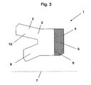
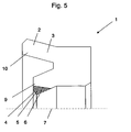
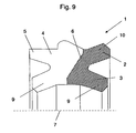
- the figures show a seal 1 with a sealing portion 2 of the inner peripheral side of a dynamic sealing lip 9 and the outer peripheral side is associated with a static sealing lip 10.
- the seal 1 is thus formed outside sealing and is preferably used as a piston seal in fluid technology (hydraulic / pneumatic) its use see also GB-A-1 142 265 ,
- the static sealing lip 10 may be arranged on the inner peripheral side and the dynamic sealing lip on the outer peripheral side.
- Such seals are formed inside tight and are preferably used as a rod seal in fluid technology (hydraulics / pneumatics) their use.
- the sealing section 2 is formed from a first material 3 suitable for injection molding.
- the first material 3 consists of a thermoplastic polyurethane, for example based on MDI, TDI, TODI or HDI.
- the sealing portion 2 is integrally connected along a binding surface 6 with a support portion 4.
- the support section 4 is formed from a second material 5 suitable for injection molding.
- the second material 5 is made of a harder thermoplastic polyurethane.
- the binding portion 6 is penetrated by the materials 3, 5 of sealing portion 2 and support portion 4 and thereby form a material connection.
- the first material 3 has a lower hardness in this embodiment than the second material 5 and is formed elastic.
- the first material 3 in this embodiment has a higher low-temperature elasticity than the second material 5. In other embodiments, more than two materials and more than two functional areas can be performed.
- the first material 3 is introduced into a mold by means of injection molding in a first step, and in a second step the second material 5 is injection-molded into the mold brought in.
- the first material 3 has a lower melting point than the second material 5, which leads to a local melting of the first material 3 and thus to a cohesive connection.
- FIG. 1 shows a seal 1 in which the sealing portion 2 is received in a groove 8 formed by the support portion 4.
- FIG. 2 shows a seal 1 in which the binding surface 6, viewed in cross-section, is formed inclined relative to the orthogonal of the axis of symmetry 7.
- the inclination in this embodiment, in which the seal 1 is externally sealing designed such that the support portion 4 is formed along the binding surface 6 conical.
- the support portion along the binding surface 6 is correspondingly funnel-shaped.
- FIG. 3 shows a seal 1 in which the binding surface 6 is formed orthogonal to the axis of symmetry 7.
- FIG. 4 shows a seal 1 in which the binding surface 6, viewed in cross section, is wavy.
- the wave troughs and wave tips can be rounded or serrated.
- FIG. 5 shows a seal 1 in which the support portion 4 is formed as a static sealing lip 9.
- FIG. 6 shows a seal 1 in which the support portion 4 is arranged on the outer peripheral side of the sealing portion 2 and surrounds this in a partial area.
- FIG. 7 shows a seal 1 in which the support portion 4 is arranged on the outer peripheral side of the sealing portion 2 and this circumferentially completely surrounds.
- FIG. 8 shows a seal 1 which is particularly suitable for sealing translationally moving machine elements and which is effective in both directions.
- the sealing section 2 is surrounded on the outer peripheral side in a partial region of the support section 4.
- the sealing section additionally has on the outer peripheral side a further groove 11, which receives the support section 4.
- FIG. 9 also shows a seal 1 which is particularly suitable for sealing translationally moving machine elements and which is effective in both directions.
- the binding surface 6 is executed in this embodiment partially inclined to the orthogonal of the axis of symmetry 7.
Abstract
Description
Die Erfindung betrifft eine Dichtung, umfassend zumindest einen Dichtabschnitt und zumindest einen Stützabschnitt die aus voneinander abweichenden Werkstoffen gebildet sind sowie ein Verfahren zu dessen Herstellung.The invention relates to a seal, comprising at least one sealing portion and at least one support portion which are formed from divergent materials and a method for its production.
Derartige Dichtungen sind aus der
Der Erfindung liegt die Aufgabe zugrunde, eine Dichtung bereitzustellen, deren Funktionsbereiche einen auf den Anwendungsfall angepassten Werkstoff aufweisen, wobei die Dichtung einfach und kostengünstig herstellbar istThe invention has for its object to provide a seal whose functional areas have adapted to the application material, the seal is simple and inexpensive to produce
Diese Aufgabe wird mit den Merkmalen von Anspruch 1 und 11 gelöst. Auf vorteilhafte Ausgestaltungen nehmen die Unteransprüche Bezug.This object is achieved with the features of
Zur Lösung der Aufgabe umfasst die Dichtung zumindest einen Dichtabschnitt aus einem ersten zum Spritzguss geeigneten Werkstoff und zumindest einen Stützabschnitt aus einem zweiten zum Spritzguss geeigneten Werkstoff die entlang einer Bindefläche stoffschlüssig miteinander verbunden sind, wobei der Dichtabschnitt und der Stützabschnitt aus voneinander abweichenden Werkstoffen gebildet sind, wobei die Bindefläche von den Werkstoffen von Dichtabschnitt und Stützabschnitt zumindest teilweise durchdrungen ist. Die Dichtung kann dabei im Spritzguss-Verfahren gefertigt sein. Zur Herstellung der Dichtung sind nur wenig Verfahrensschritte erforderlich und es wird ein hoher Automatisierungsgrad erreicht. Jeder der Abschnitte kann mit einem für seinen Anwendungsfall optimierten Werkstoff ausgerüstet sein, wobei die Werkstoffe durch die stoffschlüssige Verbindung fest miteinander verbunden sind. Durch die Durchdringung der Bindefläche durch die Werkstoffe der Abschnitte sind dazu keine Bindemittel wie beispielsweise Klebstoffe erforderlich. Die Dichtung ist besonders bei innen- und/oder außendichtenden Hydraulikdichtungen oder Pneumatikdichtungen vorteilhaft.To achieve the object, the seal comprises at least one sealing section made of a first material suitable for injection molding and at least one support section made of a second material suitable for injection molding, which are materially connected to each other along a bonding surface, wherein the sealing section and the support section are formed from mutually differing materials, wherein the bonding surface is at least partially penetrated by the materials of sealing portion and support portion. The seal can be made by injection molding. To produce the seal, only a few process steps are required and a high degree of automation is achieved. Each of the sections can be equipped with a material optimized for its application, wherein the materials are firmly connected to each other by the material connection. Due to the penetration of the bonding surface by the materials of the sections no binders such as adhesives are required. The seal is particularly advantageous for internal and / or external sealing hydraulic seals or pneumatic seals.
Die Bindefläche kann im Querschnitt betrachtet, zumindest teilweise gegen die Orthogonale der Symmetrieachse geneigt ausgebildet sein. Dabei ist die Bindefläche in Teilabschnitten geneigt ausgebildet. Auftretende Scherspannungen durch auf die Dichtung einwirkende Drücke, die insbesondere bei der Verwendung der Dichtung als Kolben- und/oder Stangendichtung auftreten, werden durch die Ausgestaltung der Dichtung gemindert.The binding surface can be viewed in cross-section, at least partially inclined relative to the orthogonal of the axis of symmetry. In this case, the binding surface is formed inclined in sections. Occurring shear stresses by acting on the seal pressures, the occur especially when using the seal as a piston and / or rod seal are reduced by the design of the seal.
Die Bindefläche kann im Querschnitt betrachtet, gegen die Symmetrieachse geneigt ausgebildet sein. Bei dieser Ausgestaltung ist die Bindefläche über die gesamte Länge geneigt ausgebildet.The binding surface can be viewed in cross-section, formed inclined relative to the axis of symmetry. In this embodiment, the binding surface is formed inclined over the entire length.
Die Bindefläche kann im Querschnitt betrachtet, wellenförmig ausgebildet sein. Die Spitzen und Täler können dabei zickzackförmig oder verrundet ausgeführt sein. Durch diese Ausgestaltung ergibt sich neben dem Stoffschluss zusätzlich ein Formschluss von Dichtabschnitt und Stützabschnitt.The binding surface can be viewed in cross section, wavy. The peaks and valleys can be executed zigzag or rounded. By this configuration, in addition to the material connection additionally results in a positive connection of sealing section and support section.
Der Dichtabschnitt kann in einer vom Stützabschnitt ausgebildeten Nut aufgenommen sein. Bei dieser Ausgestaltung ergibt sich ebenfalls ergänzend zum Stoffschluss zwischen Dichtabschnitt und Stützabschnitt ein Formschluss.The sealing portion may be received in a groove formed by the support portion. In this embodiment also results in addition to the material connection between sealing portion and support portion a positive connection.
Der erste Werkstoff kann eine geringere Härte aufweisen als der zweite Werkstoff. Dadurch ergibt sich durch den weicheren ersten Werkstoff, der mit einem relativ zu diesem bewegten abzudichtenden Maschinenelement in Berührung kommt, eine höhere Dichtheit des Maschinenelements und der Dichtung. Durch den härteren zweite Werkstoff erhöht sich die Stabilität des Stützabschnittes.The first material may have a lower hardness than the second material. This results from the softer first material, which comes into contact with a relative to this moving sealed machine element, a higher density of the machine element and the seal. The harder second material increases the stability of the support section.
Der erste Werkstoff kann elastischer sein als der zweite Werkstoff. Dadurch ergibt sich eine Dichtung mit einem flexiblen Dichtabschnitt und einen steiferen Stützabschnitt. Dadurch kann die Dichtung derart gestaltet werden, dass der Dichtabschnitt auch bei exzentrischen Bewegungen immer an dem abzudichtenden Maschinenelement anliegt, während der Stützabschnitt härter ausgebildet ist die Dichtung versteift.The first material may be more elastic than the second material. This results in a seal with a flexible sealing portion and a stiffer support portion. Thereby, the seal can be designed such that the sealing portion is always applied even with eccentric movements of the machine element to be sealed, while the support portion is harder formed stiffens the seal.
Dass der erste Werkstoff kann eine höhere Tieftemperaturelastizität aufweisen als der zweite Werkstoff. Dadurch kann die Dichtung derart gestaltet sein, dass der Dichtabschnitt auch bei tieferen Temperaturen zuverlässig abdichtet. Eine größere Flexibilität des Stützabschnittes ist dabei nicht erforderlich.That the first material can have a higher low-temperature elasticity than the second material. This allows the seal to be designed such that the sealing portion reliably seals even at lower temperatures. A greater flexibility of the support section is not required.
Der erste und der zweite Werkstoff können aus unterschiedlichen thermoplastischen Elastomeren gebildet sein. Die Formgebung von thermoplastischen Elastomeren kann im Spritzgussverfahren erfolgen.The first and second materials may be formed of different thermoplastic elastomers. The molding of thermoplastic elastomers can be done by injection molding.
Der erste und der zweite Werkstoff können aus unterschiedlichen thermoplastischen Polyurethanen gebildet sein. Thermoplastische Polyurethane sind kostengünstig und weisen gute Abriebfestigkeiten und gute Reibungswerte auf.The first and the second material may be formed of different thermoplastic polyurethanes. Thermoplastic polyurethanes are inexpensive and have good abrasion resistance and good friction values.
Die Aufgabe wird auch durch ein Verfahren zur Herstellung einer Dichtung gelöst bei dem in einem ersten Schritt ein erster polymerer Werkstoff mittels Spritzguss in ein Formwerkzeug eingebracht wird und in einem zweiten Schritt ein zweiter Werkstoff mittels Spritzguss in das Formwerkzeug eingebracht wird. Zur Herstellung der Dichtung ist dabei nur ein Formgebungswerkzeug erforderlich. Die Fertigung kann kontinuierlich erfolgen, da der erste Werkstoff im Formwerkzeug verbleibt und der zweite Werkstoff auf den ersten Werkstoff aufgespritzt wird. Dem Formwerkzeug wird abschließend die komplett hergestellte Dichtung entnommen. Die Abschnitte sind stoffschlüssig miteinander verbunden, wobei sich die Werkstoffe teilweise gegenseitig durchdringen. Die Durchdringung erfolgt drucklos durch lokales Aufschmelzen im Bereich der Bindeflächen beispielsweise durch den Spritzgussprozess oder durch Reibschweißen. Für die Verbindung von Dichtabschnitt und Stützabschnitt sind keine Bindemittel erforderlich.The object is also achieved by a method for producing a seal in which in a first step, a first polymeric material is introduced by injection molding in a mold and in a second step, a second material is introduced by injection molding in the mold. For the preparation of the seal while only a shaping tool is required. The production can be continuous, since the first material remains in the mold and the second material is sprayed onto the first material. The mold is finally removed from the completely manufactured seal. The sections are materially interconnected, whereby the materials partially penetrate each other. The penetration takes place without pressure by local melting in the area of the bonding surfaces, for example by the injection molding process or by friction welding. For the connection of sealing section and support section no binders are required.
Der erste Werkstoff kann einen niedrigeren Schmelzpunkt aufweisen als der zweite Werkstoff. Dadurch wird beim Einspritzen des zweiten Werkstoffes in das Formwerkzeug der erste Werkstoff oberflächlich aufgeschmolzen. Dabei durchdringen sich die Werkstoffe und es ergibt sich eine stoffschlüssige Verbindung. Der Einsatz von Bindemitteln ist dabei nicht erforderlich. Die Durchdringung der Werkstoffe erfolgt im gleichen Verfahrensschritt wie das Einspritzen des zweiten Werkstoffen, wodurch sich die Herstellung der Dichtung vereinfacht.The first material may have a lower melting point than the second material. As a result, during the injection of the second material into the mold, the first material is melted on the surface. The materials penetrate and a cohesive connection results. The use of binders is not required. The penetration of the materials takes place in the same process step as the injection of the second materials, which simplifies the manufacture of the seal.
Einige Ausführungsbeispiele der erfindungsgemäßen Dichtung werden nachfolgend anhand der Figuren näher erläutert. Diese zeigen, jeweils schematisch:
- Fig. 1
- eine Dichtung mit einer in den Stützkörper eingebrachten Nut;
- Fig. 2
- eine Dichtung mit einer gegen die Orthogonale der Symmetrieachse geneigten Bindefläche;
- Fig. 3
- eine erfindungsgemäße Dichtung;
- Fig. 4
- eine Dichtung mit einer wellenförmigen Dichtung;
- Fig. 5
- eine Dichtung mit einem Stützabschnitt im Bereich der statischen Dichtung;
- Fig. 6
- eine Dichtung mit einem außenumfangsseitig verlaufenden Stützabschnitt;
- Fig. 7
- eine Dichtung mit einem außenumfangsseitig verlaufenden Stützabschnitt;
- Fig. 8
- eine zweiseitig wirkende Dichtung;
- Fig. 9
- eine zweiseitig wirkende Dichtung.
- Fig. 1
- a seal with a groove introduced into the support body;
- Fig. 2
- a gasket having a binding surface inclined against the orthogonal of the axis of symmetry;
- Fig. 3
- a seal according to the invention;
- Fig. 4
- a seal with a wave-shaped seal;
- Fig. 5
- a seal having a support portion in the region of the static seal;
- Fig. 6
- a seal with an outer peripheral side extending support portion;
- Fig. 7
- a seal with an outer peripheral side extending support portion;
- Fig. 8
- a double-acting seal;
- Fig. 9
- a two-sided seal.
Die Figuren zeigen eine Dichtung 1 mit einen Dichtabschnitt 2 der innenumfangsseitig eine dynamisch Dichtlippe 9 und außenumfangsseitig eine statische Dichtlippe 10 zugeordnet ist. Die Dichtung 1 ist damit außendichtend ausgebildet und findet vorzugsweise als Kolbendichtung in der Fluidtechnik (Hydraulik/Pneumatik) ihre Verwendung siehe auch
Zur Herstellung der Dichtung 1 wird in einem ersten Schritt der erster Werkstoff 3 mittels Spritzguss in ein Formwerkzeug eingebracht wird und in einem zweiten Schritt der zweiter Werkstoff 5 mittels Spritzguss in das Formwerkzeug eingebracht. Dabei weist der erste Werkstoff 3 einen niedrigeren Schmelzpunkt auf als der zweite Werkstoff 5, was zu einem lokalen Aufschmelzen des ersten Werkstoffes 3 und damit zu einer stoffschlüssigen Verbindung führt.To produce the
Claims (12)
- Piston or rod seal (1), comprising at least one sealing section (2), the seal being assigned a dynamic sealing lip (9) and a static sealing lip (10) and being composed of a first material (3) suitable for injection moulding, the seal also comprising at least one supporting section (4) made of a second material (5) suitable for injection moulding, wherein the sealing section (2) and the supporting section (4) are formed from different materials (3, 5), characterized in that the sections (2, 4) are connected to each other along a binding surface (6) with a cohesive material joint, with the binding surface (6) being at least partially penetrated by the materials (3, 5) of the sealing section (2) and supporting section (4).
- Seal according to Claim 1, characterized in that the binding surface (6), as viewed in cross section, is designed such that it is at least partially inclined towards the orthogonal of the axis of symmetry (7).
- Seal according to Claim 1 or 2, characterized in that the binding surface (6), as viewed in cross section, is designed such that it is inclined towards the orthogonal of the axis of symmetry (7).
- Seal according to one of Claims 1 to 3,
characterized in that the binding surface (6), as viewed in cross section, is of corrugated design. - Seal according to one of Claims 1 to 4, characterized in that the sealing section (2) is accommodated in a groove (8) formed by the supporting section (4).
- Seal according to one of Claims 1 to 5, characterized in that the first material (3) is less hard than the second material (5).
- Seal according to one of Claims 1 to 6, characterized in that the first material (3) is more elastic than the second material (5).
- Seal according to one of Claims 1 to 7, characterized in that the first material (3) has a higher low-temperature elasticity than the second material (5).
- Seal according to one of Claims 1 to 8, characterized in that the first and the second material (3, 5) are formed from different thermoplastic elastomers.
- Seal according to Claim 9, characterized in that the first and the second material (3, 5) are formed from different thermoplastic polyurethanes.
- Method for producing a seal (1) according to one of the preceding claims, in which, in a first step, a first material (3) is placed into a die by means of injection moulding and, in a second step, a second material (5) is placed into the die by means of injection moulding.
- Method according to Claim 11, characterized in that the first material (3) has a lower melting point than the second material (5).
Applications Claiming Priority (1)
| Application Number | Priority Date | Filing Date | Title |
|---|---|---|---|
| DE102005012800 | 2005-03-19 |
Publications (2)
| Publication Number | Publication Date |
|---|---|
| EP1703181A1 EP1703181A1 (en) | 2006-09-20 |
| EP1703181B1 true EP1703181B1 (en) | 2009-03-11 |
Family
ID=36589181
Family Applications (1)
| Application Number | Title | Priority Date | Filing Date |
|---|---|---|---|
| EP05011814A Active EP1703181B1 (en) | 2005-03-19 | 2005-06-01 | Sealing |
Country Status (3)
| Country | Link |
|---|---|
| EP (1) | EP1703181B1 (en) |
| AT (1) | ATE425390T1 (en) |
| DE (1) | DE502005006802D1 (en) |
Cited By (1)
| Publication number | Priority date | Publication date | Assignee | Title |
|---|---|---|---|---|
| DE102013006587A1 (en) | 2013-04-08 | 2014-11-06 | Wendel Frick | Housing with molded, elastic seal (functional housing) |
Families Citing this family (6)
| Publication number | Priority date | Publication date | Assignee | Title |
|---|---|---|---|---|
| US7604243B2 (en) * | 2006-03-14 | 2009-10-20 | Macrotech Polyseal, Inc. | Composite seals, seal structures and related methods |
| DE202007012050U1 (en) * | 2007-08-29 | 2007-10-25 | Burgmann Industries Gmbh & Co. Kg | Sealing element, in particular secondary sealing element of a mechanical seal |
| DE102012022465B4 (en) * | 2012-11-15 | 2014-09-25 | Eagleburgmann Germany Gmbh & Co. Kg | Mechanical seal assembly with improved secondary seal |
| EP3032135A1 (en) | 2014-12-12 | 2016-06-15 | Carl Freudenberg KG | Shock absorber and its use |
| DE102015008987B4 (en) | 2014-12-12 | 2016-08-11 | Carl Freudenberg Kg | Shock absorber and its use |
| WO2017195770A1 (en) | 2016-05-13 | 2017-11-16 | イーグル工業株式会社 | Sealing structure |
Citations (1)
| Publication number | Priority date | Publication date | Assignee | Title |
|---|---|---|---|---|
| GB1142265A (en) * | 1967-02-14 | 1969-02-05 | Trist Mouldings & Seals Ltd | Improvements relating to sealing rings |
Family Cites Families (6)
| Publication number | Priority date | Publication date | Assignee | Title |
|---|---|---|---|---|
| US3918726A (en) * | 1974-01-28 | 1975-11-11 | Jack M Kramer | Flexible seal ring |
| GB2028439A (en) * | 1977-12-13 | 1980-03-05 | Sealol | High Pressure Seal |
| US4630833A (en) * | 1983-01-19 | 1986-12-23 | Otis Engineering Corporation | Molded ring seal with end support rings |
| US5032335A (en) | 1989-07-12 | 1991-07-16 | Mather Seal Company | Manufacture of sealing elements of composite sintered polymeric material |
| EP1087157A3 (en) * | 1999-09-27 | 2003-01-08 | Greene, Tweed Of Delaware, Inc. | Seal and protective shield |
| US20050098963A1 (en) * | 2003-11-06 | 2005-05-12 | Omax Corporation | One-piece extrusion-resistant seal |
-
2005
- 2005-06-01 AT AT05011814T patent/ATE425390T1/en not_active IP Right Cessation
- 2005-06-01 EP EP05011814A patent/EP1703181B1/en active Active
- 2005-06-01 DE DE502005006802T patent/DE502005006802D1/en active Active
Patent Citations (1)
| Publication number | Priority date | Publication date | Assignee | Title |
|---|---|---|---|---|
| GB1142265A (en) * | 1967-02-14 | 1969-02-05 | Trist Mouldings & Seals Ltd | Improvements relating to sealing rings |
Cited By (1)
| Publication number | Priority date | Publication date | Assignee | Title |
|---|---|---|---|---|
| DE102013006587A1 (en) | 2013-04-08 | 2014-11-06 | Wendel Frick | Housing with molded, elastic seal (functional housing) |
Also Published As
| Publication number | Publication date |
|---|---|
| DE502005006802D1 (en) | 2009-04-23 |
| EP1703181A1 (en) | 2006-09-20 |
| ATE425390T1 (en) | 2009-03-15 |
Similar Documents
| Publication | Publication Date | Title |
|---|---|---|
| EP1703181B1 (en) | Sealing | |
| DE2503807C2 (en) | Flexible sealing ring | |
| DE3509923C2 (en) | Spring element | |
| DE102005014128B4 (en) | Composite hose and method for its manufacture | |
| EP1041318B1 (en) | Sealing ring | |
| EP1612066A1 (en) | Disc ring for a sliding-contact bearing | |
| DE10315333B4 (en) | poetry | |
| EP0627582A1 (en) | Seal arrangement | |
| WO2007012528A2 (en) | Sleeve in particular outer sleeve for an elastomeric bearing and elastomeric bearing with such a sleeve | |
| EP2554878B1 (en) | Seal | |
| EP2226544B1 (en) | Sealing ring with serrated profile | |
| DE4004052A1 (en) | SEALING RING AND METHOD FOR THE PRODUCTION THEREOF | |
| DE4312629C1 (en) | Elastomeric gasket | |
| EP2163794B1 (en) | Seal ring with a ring-shaped metallic holder and method for producing a seal ring | |
| EP1136734A1 (en) | Seal, especially for flanged connections | |
| DE19638321C2 (en) | Mechanical seal with support ring | |
| EP0058211B1 (en) | Self-sealing washer | |
| EP1715221B1 (en) | Fixing of the end part of a bellow to a connecting part | |
| DE3442807A1 (en) | GASKET UNITS FOR HIGH PRESSURES | |
| EP0861999B1 (en) | Sealing ring | |
| DE19927619B4 (en) | Sealing device for a swivel motor | |
| EP1818589B1 (en) | Sealing ring and sealing device with the sealing ring | |
| DE102009026711A1 (en) | Shaft seal | |
| EP3464963A1 (en) | Groove ring seal and method for production thereof | |
| EP2522791A1 (en) | Rubber profile for connecting gutter sections |
Legal Events
| Date | Code | Title | Description |
|---|---|---|---|
| PUAI | Public reference made under article 153(3) epc to a published international application that has entered the european phase |
Free format text: ORIGINAL CODE: 0009012 |
|
| 17P | Request for examination filed |
Effective date: 20060714 |
|
| AK | Designated contracting states |
Kind code of ref document: A1 Designated state(s): AT BE BG CH CY CZ DE DK EE ES FI FR GB GR HU IE IS IT LI LT LU MC NL PL PT RO SE SI SK TR |
|
| AX | Request for extension of the european patent |
Extension state: AL BA HR LV MK YU |
|
| 17Q | First examination report despatched |
Effective date: 20061116 |
|
| AKX | Designation fees paid |
Designated state(s): AT BE BG CH CY CZ DE DK EE ES FI FR GB GR HU IE IS IT LI LT LU MC NL PL PT RO SE SI SK TR |
|
| GRAP | Despatch of communication of intention to grant a patent |
Free format text: ORIGINAL CODE: EPIDOSNIGR1 |
|
| GRAS | Grant fee paid |
Free format text: ORIGINAL CODE: EPIDOSNIGR3 |
|
| GRAA | (expected) grant |
Free format text: ORIGINAL CODE: 0009210 |
|
| RIN1 | Information on inventor provided before grant (corrected) |
Inventor name: DABISCH, THOMAS Inventor name: FREITAG, WERNER Inventor name: HIEBER, JUERGEN Inventor name: JAECKEL, JUERGEN Inventor name: KNAPP, WERNER Inventor name: BRAUN, OTMAR |
|
| AK | Designated contracting states |
Kind code of ref document: B1 Designated state(s): AT BE BG CH CY CZ DE DK EE ES FI FR GB GR HU IE IS IT LI LT LU MC NL PL PT RO SE SI SK TR |
|
| REG | Reference to a national code |
Ref country code: GB Ref legal event code: FG4D Free format text: NOT ENGLISH |
|
| REG | Reference to a national code |
Ref country code: CH Ref legal event code: EP |
|
| REG | Reference to a national code |
Ref country code: IE Ref legal event code: FG4D Free format text: LANGUAGE OF EP DOCUMENT: GERMAN |
|
| REF | Corresponds to: |
Ref document number: 502005006802 Country of ref document: DE Date of ref document: 20090423 Kind code of ref document: P |
|
| REG | Reference to a national code |
Ref country code: SE Ref legal event code: TRGR |
|
| PG25 | Lapsed in a contracting state [announced via postgrant information from national office to epo] |
Ref country code: LT Free format text: LAPSE BECAUSE OF FAILURE TO SUBMIT A TRANSLATION OF THE DESCRIPTION OR TO PAY THE FEE WITHIN THE PRESCRIBED TIME-LIMIT Effective date: 20090311 Ref country code: SI Free format text: LAPSE BECAUSE OF FAILURE TO SUBMIT A TRANSLATION OF THE DESCRIPTION OR TO PAY THE FEE WITHIN THE PRESCRIBED TIME-LIMIT Effective date: 20090311 Ref country code: NL Free format text: LAPSE BECAUSE OF FAILURE TO SUBMIT A TRANSLATION OF THE DESCRIPTION OR TO PAY THE FEE WITHIN THE PRESCRIBED TIME-LIMIT Effective date: 20090311 |
|
| NLV1 | Nl: lapsed or annulled due to failure to fulfill the requirements of art. 29p and 29m of the patents act | ||
| PG25 | Lapsed in a contracting state [announced via postgrant information from national office to epo] |
Ref country code: PL Free format text: LAPSE BECAUSE OF FAILURE TO SUBMIT A TRANSLATION OF THE DESCRIPTION OR TO PAY THE FEE WITHIN THE PRESCRIBED TIME-LIMIT Effective date: 20090311 |
|
| REG | Reference to a national code |
Ref country code: IE Ref legal event code: FD4D |
|
| PG25 | Lapsed in a contracting state [announced via postgrant information from national office to epo] |
Ref country code: ES Free format text: LAPSE BECAUSE OF FAILURE TO SUBMIT A TRANSLATION OF THE DESCRIPTION OR TO PAY THE FEE WITHIN THE PRESCRIBED TIME-LIMIT Effective date: 20090622 Ref country code: EE Free format text: LAPSE BECAUSE OF FAILURE TO SUBMIT A TRANSLATION OF THE DESCRIPTION OR TO PAY THE FEE WITHIN THE PRESCRIBED TIME-LIMIT Effective date: 20090311 Ref country code: IE Free format text: LAPSE BECAUSE OF FAILURE TO SUBMIT A TRANSLATION OF THE DESCRIPTION OR TO PAY THE FEE WITHIN THE PRESCRIBED TIME-LIMIT Effective date: 20090311 Ref country code: PT Free format text: LAPSE BECAUSE OF FAILURE TO SUBMIT A TRANSLATION OF THE DESCRIPTION OR TO PAY THE FEE WITHIN THE PRESCRIBED TIME-LIMIT Effective date: 20090824 |
|
| PG25 | Lapsed in a contracting state [announced via postgrant information from national office to epo] |
Ref country code: SK Free format text: LAPSE BECAUSE OF FAILURE TO SUBMIT A TRANSLATION OF THE DESCRIPTION OR TO PAY THE FEE WITHIN THE PRESCRIBED TIME-LIMIT Effective date: 20090311 Ref country code: IS Free format text: LAPSE BECAUSE OF FAILURE TO SUBMIT A TRANSLATION OF THE DESCRIPTION OR TO PAY THE FEE WITHIN THE PRESCRIBED TIME-LIMIT Effective date: 20090711 Ref country code: RO Free format text: LAPSE BECAUSE OF FAILURE TO SUBMIT A TRANSLATION OF THE DESCRIPTION OR TO PAY THE FEE WITHIN THE PRESCRIBED TIME-LIMIT Effective date: 20090311 |
|
| BERE | Be: lapsed |
Owner name: CARL FREUDENBERG K.G. Effective date: 20090630 |
|
| PLBE | No opposition filed within time limit |
Free format text: ORIGINAL CODE: 0009261 |
|
| STAA | Information on the status of an ep patent application or granted ep patent |
Free format text: STATUS: NO OPPOSITION FILED WITHIN TIME LIMIT |
|
| PG25 | Lapsed in a contracting state [announced via postgrant information from national office to epo] |
Ref country code: BG Free format text: LAPSE BECAUSE OF FAILURE TO SUBMIT A TRANSLATION OF THE DESCRIPTION OR TO PAY THE FEE WITHIN THE PRESCRIBED TIME-LIMIT Effective date: 20090611 Ref country code: MC Free format text: LAPSE BECAUSE OF NON-PAYMENT OF DUE FEES Effective date: 20090630 Ref country code: DK Free format text: LAPSE BECAUSE OF FAILURE TO SUBMIT A TRANSLATION OF THE DESCRIPTION OR TO PAY THE FEE WITHIN THE PRESCRIBED TIME-LIMIT Effective date: 20090311 |
|
| REG | Reference to a national code |
Ref country code: CH Ref legal event code: PL |
|
| 26N | No opposition filed |
Effective date: 20091214 |
|
| PG25 | Lapsed in a contracting state [announced via postgrant information from national office to epo] |
Ref country code: LI Free format text: LAPSE BECAUSE OF NON-PAYMENT OF DUE FEES Effective date: 20090630 Ref country code: CH Free format text: LAPSE BECAUSE OF NON-PAYMENT OF DUE FEES Effective date: 20090630 |
|
| PG25 | Lapsed in a contracting state [announced via postgrant information from national office to epo] |
Ref country code: BE Free format text: LAPSE BECAUSE OF NON-PAYMENT OF DUE FEES Effective date: 20090630 |
|
| PG25 | Lapsed in a contracting state [announced via postgrant information from national office to epo] |
Ref country code: AT Free format text: LAPSE BECAUSE OF NON-PAYMENT OF DUE FEES Effective date: 20090601 |
|
| PG25 | Lapsed in a contracting state [announced via postgrant information from national office to epo] |
Ref country code: GR Free format text: LAPSE BECAUSE OF FAILURE TO SUBMIT A TRANSLATION OF THE DESCRIPTION OR TO PAY THE FEE WITHIN THE PRESCRIBED TIME-LIMIT Effective date: 20090612 |
|
| PG25 | Lapsed in a contracting state [announced via postgrant information from national office to epo] |
Ref country code: LU Free format text: LAPSE BECAUSE OF NON-PAYMENT OF DUE FEES Effective date: 20090601 |
|
| PG25 | Lapsed in a contracting state [announced via postgrant information from national office to epo] |
Ref country code: HU Free format text: LAPSE BECAUSE OF FAILURE TO SUBMIT A TRANSLATION OF THE DESCRIPTION OR TO PAY THE FEE WITHIN THE PRESCRIBED TIME-LIMIT Effective date: 20090912 |
|
| PG25 | Lapsed in a contracting state [announced via postgrant information from national office to epo] |
Ref country code: TR Free format text: LAPSE BECAUSE OF FAILURE TO SUBMIT A TRANSLATION OF THE DESCRIPTION OR TO PAY THE FEE WITHIN THE PRESCRIBED TIME-LIMIT Effective date: 20090311 |
|
| PG25 | Lapsed in a contracting state [announced via postgrant information from national office to epo] |
Ref country code: CY Free format text: LAPSE BECAUSE OF FAILURE TO SUBMIT A TRANSLATION OF THE DESCRIPTION OR TO PAY THE FEE WITHIN THE PRESCRIBED TIME-LIMIT Effective date: 20090311 |
|
| REG | Reference to a national code |
Ref country code: FR Ref legal event code: PLFP Year of fee payment: 11 |
|
| REG | Reference to a national code |
Ref country code: FR Ref legal event code: PLFP Year of fee payment: 12 |
|
| REG | Reference to a national code |
Ref country code: FR Ref legal event code: PLFP Year of fee payment: 13 |
|
| REG | Reference to a national code |
Ref country code: FR Ref legal event code: PLFP Year of fee payment: 14 |
|
| PGFP | Annual fee paid to national office [announced via postgrant information from national office to epo] |
Ref country code: FR Payment date: 20230623 Year of fee payment: 19 Ref country code: DE Payment date: 20230627 Year of fee payment: 19 Ref country code: CZ Payment date: 20230524 Year of fee payment: 19 |
|
| PGFP | Annual fee paid to national office [announced via postgrant information from national office to epo] |
Ref country code: SE Payment date: 20230622 Year of fee payment: 19 Ref country code: FI Payment date: 20230620 Year of fee payment: 19 |
|
| PGFP | Annual fee paid to national office [announced via postgrant information from national office to epo] |
Ref country code: IT Payment date: 20230629 Year of fee payment: 19 Ref country code: GB Payment date: 20230622 Year of fee payment: 19 |