EP1703171A1 - A ball screw - Google Patents
A ball screw Download PDFInfo
- Publication number
- EP1703171A1 EP1703171A1 EP06111182A EP06111182A EP1703171A1 EP 1703171 A1 EP1703171 A1 EP 1703171A1 EP 06111182 A EP06111182 A EP 06111182A EP 06111182 A EP06111182 A EP 06111182A EP 1703171 A1 EP1703171 A1 EP 1703171A1
- Authority
- EP
- European Patent Office
- Prior art keywords
- nut
- bridge member
- screw
- ball screw
- bridge
- Prior art date
- Legal status (The legal status is an assumption and is not a legal conclusion. Google has not performed a legal analysis and makes no representation as to the accuracy of the status listed.)
- Granted
Links
Images


Classifications
-
- F—MECHANICAL ENGINEERING; LIGHTING; HEATING; WEAPONS; BLASTING
- F16—ENGINEERING ELEMENTS AND UNITS; GENERAL MEASURES FOR PRODUCING AND MAINTAINING EFFECTIVE FUNCTIONING OF MACHINES OR INSTALLATIONS; THERMAL INSULATION IN GENERAL
- F16H—GEARING
- F16H25/00—Gearings comprising primarily only cams, cam-followers and screw-and-nut mechanisms
- F16H25/18—Gearings comprising primarily only cams, cam-followers and screw-and-nut mechanisms for conveying or interconverting oscillating or reciprocating motions
- F16H25/20—Screw mechanisms
- F16H25/22—Screw mechanisms with balls, rollers, or similar members between the co-operating parts; Elements essential to the use of such members
- F16H25/2204—Screw mechanisms with balls, rollers, or similar members between the co-operating parts; Elements essential to the use of such members with balls
- F16H25/2214—Screw mechanisms with balls, rollers, or similar members between the co-operating parts; Elements essential to the use of such members with balls with elements for guiding the circulating balls
- F16H25/2223—Cross over deflectors between adjacent thread turns, e.g. S-form deflectors connecting neighbouring threads
-
- F—MECHANICAL ENGINEERING; LIGHTING; HEATING; WEAPONS; BLASTING
- F16—ENGINEERING ELEMENTS AND UNITS; GENERAL MEASURES FOR PRODUCING AND MAINTAINING EFFECTIVE FUNCTIONING OF MACHINES OR INSTALLATIONS; THERMAL INSULATION IN GENERAL
- F16H—GEARING
- F16H25/00—Gearings comprising primarily only cams, cam-followers and screw-and-nut mechanisms
- F16H25/18—Gearings comprising primarily only cams, cam-followers and screw-and-nut mechanisms for conveying or interconverting oscillating or reciprocating motions
- F16H25/20—Screw mechanisms
- F16H25/24—Elements essential to such mechanisms, e.g. screws, nuts
-
- F—MECHANICAL ENGINEERING; LIGHTING; HEATING; WEAPONS; BLASTING
- F16—ENGINEERING ELEMENTS AND UNITS; GENERAL MEASURES FOR PRODUCING AND MAINTAINING EFFECTIVE FUNCTIONING OF MACHINES OR INSTALLATIONS; THERMAL INSULATION IN GENERAL
- F16H—GEARING
- F16H25/00—Gearings comprising primarily only cams, cam-followers and screw-and-nut mechanisms
- F16H25/18—Gearings comprising primarily only cams, cam-followers and screw-and-nut mechanisms for conveying or interconverting oscillating or reciprocating motions
- F16H25/20—Screw mechanisms
- F16H25/24—Elements essential to such mechanisms, e.g. screws, nuts
- F16H2025/2481—Special features for facilitating the manufacturing of spindles, nuts, or sleeves of screw devices
-
- Y—GENERAL TAGGING OF NEW TECHNOLOGICAL DEVELOPMENTS; GENERAL TAGGING OF CROSS-SECTIONAL TECHNOLOGIES SPANNING OVER SEVERAL SECTIONS OF THE IPC; TECHNICAL SUBJECTS COVERED BY FORMER USPC CROSS-REFERENCE ART COLLECTIONS [XRACs] AND DIGESTS
- Y10—TECHNICAL SUBJECTS COVERED BY FORMER USPC
- Y10T—TECHNICAL SUBJECTS COVERED BY FORMER US CLASSIFICATION
- Y10T74/00—Machine element or mechanism
- Y10T74/18—Mechanical movements
- Y10T74/18568—Reciprocating or oscillating to or from alternating rotary
- Y10T74/18576—Reciprocating or oscillating to or from alternating rotary including screw and nut
- Y10T74/18744—Lubrication
Definitions
- the present invention relates to a ball screw used for an electric-powered actuator of vehicle etc, and more particularly to a ball screw used under agitated oil lubrication.
- the ball screw comprises a screw shaft formed with a helical ball rolling groove on its outer circumferential surface, a nut adapted to be fitted on the screw shaft and formed with a helical screw groove on its inner circumferential surface, a large number of balls contained in a rolling passage formed by oppositely arranged screw grooves, and a circulating mechanism for bypassing the rolling passage to a radially outward circumferential passage, and used as a motion converting mechanism e.g. for converting a rotational motion of the nut to a linear motion of the screw shaft.
- the ball screw 50 comprises a screw shaft 51 formed with a helical screw groove 51a on its outer circumferential surface; a nut 52 adapted to be fitted on the screw shaft 51 and formed with a helical screw groove 52a on its inner circumferential surface; a large number of balls 53 contained in a rolling passage formed by oppositely arranged screw grooves 51a and 52a; and a bridge member (not shown) formed with a connecting groove for connecting mutually adjacent rolling grooves 52a of the nut 52 by one round.
- the nut 52 is formed on its cylindrical wall with two oil introducing apertures 54 communicating with the inside of the nut 52 in an axially spaced manner. Oil introducing portion of each aperture 54 is countersunk enabling oil to be easily introduced. Oil introduced into the inside of the nut 52 through the apertures 54 is discharged at ends of the nut 52 though gap between the nut 52 and the screw shaft 51.
- an object of the present invention to provide a ball screw which can sufficiently circulate oil within a nut to improve the life of the ball screw without increase of manufacturing cost.
- a ball screw used under agitated oil lubrication comprising: a screw shaft formed with a helical screw groove on its outer circumferential surface; a nut adapted to be fitted on the screw shaft and formed with a helical screw groove on its inner circumferential surface; a plurality of balls contained in a rolling passage formed by oppositely arranged screw grooves; and a bridge member adapted to be fitted in a bridge window formed through a barrel wall of the nut and formed with a connecting groove bypassing the rolling passage to a radially outward circumferential passage; characterized in that a notch is formed in the bridge member so as to intercommunicate the outer and inner circumferential portions of the nut.
- the notch is formed in the bridge member so as to intercommunicate the outer and inner circumferential portions of the nut, it is unnecessary to specially provide any oil introducing aperture in the nut as a conventional manner. In addition, it is possible to circulate oil without resistance without providing any oil discharging aperture although the ball screw is used in an application in which one open end of the nut is blocked.
- the bridge member is integrally formed with an arm engaging the screw groove of the nut for positioning the bridge member relative to the nut and with guide walls adapted to be caulked to side edges of the bridge window, it is possible to firmly prevent the bridge member from being radially outwardly fallen out from the bridge window.
- the bridge member is made of sintered alloy formed by MIM, it is possible to easily and exactly form the bridge member to a desired configuration and dimension although it requires high difficulty in work and has a complicated configuration.
- the guide wall of the bridge member is plastically deformable and has toughness ensuring strength of the caulked portion, and the surface of the connecting groove is hardened at least more than 30 HRC or more by heat treatment, the connecting groove in which large stress is generated has sufficient resistance to impression and wear, and the guide wall has a desirable toughness.
- the connecting groove in which large stress is generated has sufficient resistance to impression and wear, and the guide wall has a desirable toughness.
- a bridge type ball screw provided with a bridge member having properties such as strength resistance and toughness which are contrary to each other.
- the bridge member is made of carburized steel and its surface is hardened by carburizing hardening treatment, and the surface hardness of the guide wall is set at a range 15 - 23 HRC by annealing as defined in claim 5. This makes it possible to ensure strength in the caulked portion and to prevent generation of clacks during caulking.
- the ball screw of the present invention comprises a screw shaft formed with a helical screw groove on its outer circumferential surface; a nut adapted to be fitted on the screw shaft and formed with a helical screw groove on its inner circumferential surface; a plurality of balls contained in a rolling passage formed by oppositely arranged screw grooves; and a bridge member adapted to be fitted in a bridge window formed through a barrel wall of the nut and formed with a connecting groove bypassing the rolling passage to a radially outward circumferential passage; and is characterized in that a notch is formed in the bridge member so as to intercommunicate the outer and inner circumferential portions of the nut.
- Best mode for carrying out the present invention is a ball screw used under agitated oil lubrication comprising: a screw shaft formed with a helical screw groove on its outer circumferential surface; a nut adapted to be fitted on the screw shaft and formed with a helical screw groove on its inner circumferential surface; a plurality of balls contained in a rolling passage formed by oppositely arranged screw grooves; and a bridge member adapted to be fitted in a bridge window formed through a barrel wall of the nut and formed with a connecting groove bypassing the rolling passage to a radially outward circumferential passage; characterized in that the bridge member is made of sintered alloy formed by MIM, in that the bridge member is integrally formed with an arm engaging the screw groove of the nut for positioning the bridge member relative to the nut and with guide walls adapted to be caulked to side edges of the bridge window, and in that a notch is formed in the bridge member so as to intercommunicate the outer and inner circumferential portions of the nut.
- Fig. 1(a) is a plan view of one embodiment of the ball screw of the present invention
- Fig. 1(b) is a longitudinal section view of a ball screw of Fig. 1(a)
- Fig. 2(a) is a longitudinal section view of a nut of the present invention
- Fig. 2(b) is s partially broken end view of Fig. 2(a).
- the ball screw 1 comprises a screw shaft 2 formed with a helical screw groove 2a on its outer circumferential surface; a nut 3 adapted to be fitted on the screw shaft 2 and formed with a helical screw groove 3a on its inner circumferential surface; a large number of balls 4 contained in a rolling passage formed by oppositely arranged screw grooves 2a and 3a; and a bridge member 5 formed with a connecting groove 5a for connecting mutually adjacent rolling grooves 3a of the nut 3 by one round.
- each of the screw grooves 2a and 3a may be circular arc or Gothic arc configuration.
- the Gothic arc configuration is adopted from reasons that a large contacting angle with the ball 4 and a small axial gap can be ensured. This makes it possible to increase rigidity resisting against an axial load and to suppress vibration of the ball screw.
- a circular bridge window 6 to which the circular bridge member 5 is fitted is formed in a barrel of the cylindrical nut 3 so that it passes through the wall of the barrel and cuts a portion of the screw groove 3a.
- a connecting groove 5a for connecting mutually adjacent rolling grooves 3a of the nut 3 by one round is formed in the bridge member 5.
- This connecting groove 5a and a substantially one round portion of the screw groove 3a forms a rolling passage of the balls 4.
- a large number of balls 4 contained between the inner and outer screw grooves 2a and 3a forming the rolling passage roll along the screw grooves 2a and 3a, then are guided to the connecting groove 5a of the bridge member 5, climb over the ridge of the screw shaft 1, then return to the adjacent screw groove 3a, and continue to roll along the screw grooves 2a and 3a.
- the connecting groove 5a of the bridge member 5 has a "S" configuration as shown in Fig. 2(a) so as to be able to smoothly connect the adjacent screw grooves 3a of the nut 3. Accordingly, the connecting groove 5a is adapted to be connected to the screw groove 3a so that opposite opened edges 7 of the connecting groove 5a correspond to opened edges 8 of the screw groove 3a as shown in Fig. 2(b).
- the depth of the connecting groove 5a is set so that balls 4 can climb over the ridge of the screw groove 2a of the screw shaft 1 within the connecting groove 5a.
- the bridge member 5 is formed with arms 9 each having a substantially semi-cylindrical configuration at either ends of the bridge member 5 as shown in Fig. 2(a). Each arm 9 are adapted to engage the screw groove 3a of the nut 3 via a predetermined radial gap in order to axially position the bridge member 5 relative to the nut 3 and to prevent the bridge member 5 from being radially outwardly fallen out from the bridge window 6.
- the bridge member 5 is formed with recesses 10 on its radially outward surface at circumferentially opposite edges of the bridge member 5 so that a pair of guide walls 11 radially outwardly upstanding from the recesses 10. The bridge member 5 can be secured to the nut 3 by caulking the guide walls 11 to the edges of the bridge window 6.
- the incorporation of the balls 4 is carried out by applying the nut 3 to the end of the screw shaft 1, and by introducing balls 4 one by one into the space between the screw grooves 2a and 3a with rotating the nut 3 to move it along the screw shaft 1.
- the balls 4 can be also introduced into the rolling passage by using a temporary shaft.
- the bridge member 5 is made by injection molding sintered ally obtained by plastically refining metallic powder.
- plastic and binder comprising wax are mixed and then granulated to pellets from the mixed material.
- the granulated pellets are fed to a hopper of injection molding machine and injected into a mold under a melted condition to form the sintered alloy by the so-called "MIM" (Metal Injection Molding) method.
- MIM Metal Injection Molding
- metallic powder used in this embodiment is carburizing hardenable material such as precipitation hardening stainless steel SUS 630 comprising C (0.13 wt%), Ni (0.21 wt%), Cr (1.1 wt%), Cu (0.04 wt%), Mn (0.76 %), Mo (0.19 wt%), Si (0.20 wt%), and Fe (the rest).
- SUS 630 is able to increase its surface hardness by solution treatment and to obtain strong toughness and high hardness.
- the bridge member 5 When the bridge member 5 is made of carburized material such as SCM 415, it is hardened by carburizing hardening to have its surface hardness 30 - 40 HRC and the caulking portion i.e. guide wall 11 is annealed by an induction tempering apparatus to have its surface hardness 15 - 23 HRC.
- the bridge member 5 is made of precipitation hardening stainless steel such as SUS 630, it is preferable to set its surface hardness more than 30 HRC or more by solution treatment.
- SUS 630 has a characteristic feature that its alloy elements can be easily solubilized by heating the material SUS 630 to a predetermined temperature and then by quenching it.
- the connecting groove 5a in which a large stress is caused has a sufficiently high impression resistance and wear resistance.
- the toughness of the guide wall 11 forming caulking portion is also sufficiently high, it is possible to prevent generation of clacks etc. when the bridge member 5 is caulked to the nut 3.
- the ball screw of the present invention is not limited to such an example and thus it is possible to use a bridge member made by forging and cutting and adapted to be secured to the bridge window by adhesion.
- a notch 12 (shown by hatching in Fig. 2(a)) is formed in the bridge member 5. Accordingly, when the bridge member 5 is secured in the bridge window 6, the notch 12 intercommunicates the outer and inner circumferential portions of the nut 3 and thus has a function of oil introducing aperture.
- the ball screw of the present invention can be applied to a ball screw used under agitated oil lubrication such as an electric-powered actuator of vehicle.
Landscapes
- Engineering & Computer Science (AREA)
- General Engineering & Computer Science (AREA)
- Mechanical Engineering (AREA)
- Transmission Devices (AREA)
Abstract
Description
- The present invention relates to a ball screw used for an electric-powered actuator of vehicle etc, and more particularly to a ball screw used under agitated oil lubrication.
- The ball screw comprises a screw shaft formed with a helical ball rolling groove on its outer circumferential surface, a nut adapted to be fitted on the screw shaft and formed with a helical screw groove on its inner circumferential surface, a large number of balls contained in a rolling passage formed by oppositely arranged screw grooves, and a circulating mechanism for bypassing the rolling passage to a radially outward circumferential passage, and used as a motion converting mechanism e.g. for converting a rotational motion of the nut to a linear motion of the screw shaft.
- In general, there are several kinds of ball screws having different ball circulating mechanism and one of which is a bridge type. In this bridge type ball screw, the nut is fitted with a bridge member having a connecting passage for bypassing balls from their rolling passage on the screw shaft to a radially outward circumferential passage (i.e. the connecting passage formed in the bridge member). This bridge type ball screw is advantageous in its relatively simple and compact structure.
- One representative example of this bridge type ball screw is shown in Fig. 3. The
ball screw 50 comprises ascrew shaft 51 formed with ahelical screw groove 51a on its outer circumferential surface; anut 52 adapted to be fitted on thescrew shaft 51 and formed with ahelical screw groove 52a on its inner circumferential surface; a large number ofballs 53 contained in a rolling passage formed by oppositely arrangedscrew grooves rolling grooves 52a of thenut 52 by one round. In this conventional ball screw, thenut 52 is formed on its cylindrical wall with twooil introducing apertures 54 communicating with the inside of thenut 52 in an axially spaced manner. Oil introducing portion of eachaperture 54 is countersunk enabling oil to be easily introduced. Oil introduced into the inside of thenut 52 through theapertures 54 is discharged at ends of thenut 52 though gap between thenut 52 and thescrew shaft 51. - Because of provision of the
oil introducing apertures 54 communicating with a space between thescrew grooves nut 52 although it is a ball screw used under agitated oil lubrication liable to be lack of oil inside thenut 52 due to its short stroke of motion (seeJapanese Laid-open Patent Publication No. 108477/2004 - However, in this
conventional ball screw 50 it increases a manufacturing cost of theball screw 50 to specially form theoil introducing apertures 54. In addition, lack of oil would be caused when a flange for transmitting driving force to any driven element is provided on one end of thenut 52 because of blockage of oil circulation within theball screw 50 due to presence of the flange. In such a case it is necessary to provide an oil discharging apertures oppositely to the oil introducing apertures (not shown) to smoothly circulating oil through thenut 52. However this would further increase the manufacturing cost of the ball screw. - It is, therefore, an object of the present invention to provide a ball screw which can sufficiently circulate oil within a nut to improve the life of the ball screw without increase of manufacturing cost.
- For achieving the object of the present invention there is provided, according to the present invention, a ball screw used under agitated oil lubrication comprising: a screw shaft formed with a helical screw groove on its outer circumferential surface; a nut adapted to be fitted on the screw shaft and formed with a helical screw groove on its inner circumferential surface; a plurality of balls contained in a rolling passage formed by oppositely arranged screw grooves; and a bridge member adapted to be fitted in a bridge window formed through a barrel wall of the nut and formed with a connecting groove bypassing the rolling passage to a radially outward circumferential passage; characterized in that a notch is formed in the bridge member so as to intercommunicate the outer and inner circumferential portions of the nut.
- According to the ball screw nut of the present invention, since the notch is formed in the bridge member so as to intercommunicate the outer and inner circumferential portions of the nut, it is unnecessary to specially provide any oil introducing aperture in the nut as a conventional manner. In addition, it is possible to circulate oil without resistance without providing any oil discharging aperture although the ball screw is used in an application in which one open end of the nut is blocked.
- According to the present invention, since the bridge member is integrally formed with an arm engaging the screw groove of the nut for positioning the bridge member relative to the nut and with guide walls adapted to be caulked to side edges of the bridge window, it is possible to firmly prevent the bridge member from being radially outwardly fallen out from the bridge window.
- According to the present invention, the bridge member is made of sintered alloy formed by MIM, it is possible to easily and exactly form the bridge member to a desired configuration and dimension although it requires high difficulty in work and has a complicated configuration.
- According to the present invention, since the guide wall of the bridge member is plastically deformable and has toughness ensuring strength of the caulked portion, and the surface of the connecting groove is hardened at least more than 30 HRC or more by heat treatment, the connecting groove in which large stress is generated has sufficient resistance to impression and wear, and the guide wall has a desirable toughness. Thus, it is possible to prevent generation of clacks in the nut when the bridge member is fitted therein. Accordingly it is possible to provide a bridge type ball screw provided with a bridge member having properties such as strength resistance and toughness which are contrary to each other.
- Preferably the bridge member is made of carburized steel and its surface is hardened by carburizing hardening treatment, and the surface hardness of the guide wall is set at a range 15 - 23 HRC by annealing as defined in
claim 5. This makes it possible to ensure strength in the caulked portion and to prevent generation of clacks during caulking. - According to the ball screw of the present invention, it comprises a screw shaft formed with a helical screw groove on its outer circumferential surface; a nut adapted to be fitted on the screw shaft and formed with a helical screw groove on its inner circumferential surface; a plurality of balls contained in a rolling passage formed by oppositely arranged screw grooves; and a bridge member adapted to be fitted in a bridge window formed through a barrel wall of the nut and formed with a connecting groove bypassing the rolling passage to a radially outward circumferential passage; and is characterized in that a notch is formed in the bridge member so as to intercommunicate the outer and inner circumferential portions of the nut. Accordingly, it is unnecessary to specially provide any oil introducing aperture in the nut as a conventional manner. In addition, it is possible to circulate oil without resistance without providing any oil discharging aperture although the ball screw is used in an application in which one open end of the nut is blocked.
- Best mode for carrying out the present invention is a ball screw used under agitated oil lubrication comprising: a screw shaft formed with a helical screw groove on its outer circumferential surface; a nut adapted to be fitted on the screw shaft and formed with a helical screw groove on its inner circumferential surface; a plurality of balls contained in a rolling passage formed by oppositely arranged screw grooves; and a bridge member adapted to be fitted in a bridge window formed through a barrel wall of the nut and formed with a connecting groove bypassing the rolling passage to a radially outward circumferential passage; characterized in that the bridge member is made of sintered alloy formed by MIM, in that the bridge member is integrally formed with an arm engaging the screw groove of the nut for positioning the bridge member relative to the nut and with guide walls adapted to be caulked to side edges of the bridge window, and in that a notch is formed in the bridge member so as to intercommunicate the outer and inner circumferential portions of the nut.
- Additional advantages and features of the present invention will become apparent from the subsequent description and the appended claims, taken in conjunction with the accompanying drawings, wherein:
- Fig. 1(a) is a plan view of one embodiment of the ball screw of the present invention, and Fig. 1(b) is a longitudinal section view of a ball screw of Fig. 1(a);
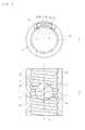
- Fig. 2(a) is a longitudinal section view of a nut of the present invention, and Fig. 2(b) is s partially broken end view of Fig. 2(a); and
- Fig. 3 is a longitudinal section view of a ball screw of the prior art.
- Embodiments of the present invention will be described with reference to accompanying drawings.
Fig. 1(a) is a plan view of one embodiment of the ball screw of the present invention, and Fig. 1(b) is a longitudinal section view of a ball screw of Fig. 1(a); and Fig. 2(a) is a longitudinal section view of a nut of the present invention, and Fig. 2(b) is s partially broken end view of Fig. 2(a). - The
ball screw 1 comprises ascrew shaft 2 formed with ahelical screw groove 2a on its outer circumferential surface; anut 3 adapted to be fitted on thescrew shaft 2 and formed with ahelical screw groove 3a on its inner circumferential surface; a large number ofballs 4 contained in a rolling passage formed by oppositely arrangedscrew grooves bridge member 5 formed with a connectinggroove 5a for connecting mutually adjacentrolling grooves 3a of thenut 3 by one round. - The longitudinal section configuration of each of the
screw grooves ball 4 and a small axial gap can be ensured. This makes it possible to increase rigidity resisting against an axial load and to suppress vibration of the ball screw. - A
circular bridge window 6 to which thecircular bridge member 5 is fitted is formed in a barrel of thecylindrical nut 3 so that it passes through the wall of the barrel and cuts a portion of thescrew groove 3a. A connectinggroove 5a for connecting mutually adjacentrolling grooves 3a of thenut 3 by one round is formed in thebridge member 5. This connectinggroove 5a and a substantially one round portion of thescrew groove 3a forms a rolling passage of theballs 4. A large number ofballs 4 contained between the inner andouter screw grooves screw grooves groove 5a of thebridge member 5, climb over the ridge of thescrew shaft 1, then return to theadjacent screw groove 3a, and continue to roll along thescrew grooves - The connecting
groove 5a of thebridge member 5 has a "S" configuration as shown in Fig. 2(a) so as to be able to smoothly connect theadjacent screw grooves 3a of thenut 3. Accordingly, the connectinggroove 5a is adapted to be connected to thescrew groove 3a so that opposite openededges 7 of the connectinggroove 5a correspond to openededges 8 of thescrew groove 3a as shown in Fig. 2(b). The depth of the connectinggroove 5a is set so thatballs 4 can climb over the ridge of thescrew groove 2a of thescrew shaft 1 within the connectinggroove 5a. - The
bridge member 5 is formed witharms 9 each having a substantially semi-cylindrical configuration at either ends of thebridge member 5 as shown in Fig. 2(a). Eacharm 9 are adapted to engage thescrew groove 3a of thenut 3 via a predetermined radial gap in order to axially position thebridge member 5 relative to thenut 3 and to prevent thebridge member 5 from being radially outwardly fallen out from thebridge window 6. In addition, as shown in Fig. 2(b), thebridge member 5 is formed withrecesses 10 on its radially outward surface at circumferentially opposite edges of thebridge member 5 so that a pair ofguide walls 11 radially outwardly upstanding from therecesses 10. Thebridge member 5 can be secured to thenut 3 by caulking theguide walls 11 to the edges of thebridge window 6. - After having mounted the
bridge member 5 in thebridge window 6 from radially inside of thenut 3, the incorporation of theballs 4 is carried out by applying thenut 3 to the end of thescrew shaft 1, and by introducingballs 4 one by one into the space between thescrew grooves nut 3 to move it along thescrew shaft 1. Theballs 4 can be also introduced into the rolling passage by using a temporary shaft. - The
bridge member 5 is made by injection molding sintered ally obtained by plastically refining metallic powder. For preparation of the injection molding, firstly, plastic and binder comprising wax are mixed and then granulated to pellets from the mixed material. The granulated pellets are fed to a hopper of injection molding machine and injected into a mold under a melted condition to form the sintered alloy by the so-called "MIM" (Metal Injection Molding) method. The sintered alloy formed by MIM can be easily and exactly formed to the bridge member of desired configuration and dimension although the bridge member requires high difficulty in work and has a complicated configuration. - One example of metallic powder used in this embodiment is carburizing hardenable material such as precipitation hardening stainless steel SUS 630 comprising C (0.13 wt%), Ni (0.21 wt%), Cr (1.1 wt%), Cu (0.04 wt%), Mn (0.76 %), Mo (0.19 wt%), Si (0.20 wt%), and Fe (the rest). SUS 630 is able to increase its surface hardness by solution treatment and to obtain strong toughness and high hardness.
- When the
bridge member 5 is made of carburized material such as SCM 415, it is hardened by carburizing hardening to have its surface hardness 30 - 40 HRC and the caulking portion i.e.guide wall 11 is annealed by an induction tempering apparatus to have its surface hardness 15 - 23 HRC. - When the surface hardness of hardened layer by carburizing hardening is less than 30 HRC, the impression resistance and wear resistance is insufficient, on the contrary, when it exceeds 40 HRC, deformation due to heat treatment of the
bridge member 5 is excessive. When the surface hardness of theguide wall 11 by annealing is less than 15 HRC, the strength of the caulking portion is insufficient, on the contrary, when it exceeds 23 HRC, clacks etc. would be caused during caulking. - When the
bridge member 5 is made of precipitation hardening stainless steel such as SUS 630, it is preferable to set its surface hardness more than 30 HRC or more by solution treatment. SUS 630 has a characteristic feature that its alloy elements can be easily solubilized by heating the material SUS 630 to a predetermined temperature and then by quenching it. - Since the
bridge member 5 is made of these carburized materials or sintered material formed of precipitation hardening stainless steel by MIM, the connectinggroove 5a in which a large stress is caused has a sufficiently high impression resistance and wear resistance. In addition, since the toughness of theguide wall 11 forming caulking portion is also sufficiently high, it is possible to prevent generation of clacks etc. when thebridge member 5 is caulked to thenut 3. Although it is shown an example in which thebridge member 5 is made of sintered alloy formed by MIM and caulked to thenut 3, the ball screw of the present invention is not limited to such an example and thus it is possible to use a bridge member made by forging and cutting and adapted to be secured to the bridge window by adhesion. - According to the present invention, a notch 12 (shown by hatching in Fig. 2(a)) is formed in the
bridge member 5. Accordingly, when thebridge member 5 is secured in thebridge window 6, thenotch 12 intercommunicates the outer and inner circumferential portions of thenut 3 and thus has a function of oil introducing aperture. - In the illustrated embodiment, it is shown a
circular bridge member 5 and a correspondingcircular bridge window 6, however other configuration e.g. an oval bridge member and a corresponding oval bridge window may be adopted. - According to the present invention, it is unnecessary to specially provide any oil introducing aperture in the nut as a conventional manner. In addition, it is possible to circulate oil without resistance without providing any oil discharging aperture although the ball screw is used in an application in which one open end of the nut is blocked.
- The ball screw of the present invention can be applied to a ball screw used under agitated oil lubrication such as an electric-powered actuator of vehicle.
- The present invention has been described with reference to the preferred embodiments. Obviously, modifications and alternations will occur to those of ordinary skill in the art upon reading and understanding the preceding detailed description. It is intended that the present invention be construed as including all such alternations and modifications insofar as they come within the scope of the appended claims or the equivalents thereof.
Claims (5)
- A ball screw (1) used under agitated oil lubrication comprising:a screw shaft (2) formed with a helical screw groove (2a) on its outer circumferential surface;a nut (3) adapted to be fitted on the screw shaft (2) and formed with a helical screw groove (3a) on its inner circumferential surface;a plurality of balls (4) contained in a rolling passage formed by oppositely arranged screw grooves (2a and 3a); anda bridge member (5) adapted to be fitted in a bridge window (6) formed through a barrel wall of the nut (3) and formed with a connecting groove (5a) bypassing the rolling passage to a radially outward circumferential passage; characterized in that a notch is formed in the bridge member (5) so as to intercommunicate the outer and inner circumferential portions of the nut (3).
- A ball screw of claim 1 wherein the bridge member (5) is integrally formed with an arm (9) engaging the screw groove (3a) of the nut (3) for positioning the bridge member (5) relative to the nut (3) and with guide walls (11) adapted to be caulked to side edges of the bridge window (6).
- A ball screw of claim 1 or 2 wherein the bridge member (5) is made of sintered alloy formed by MIM.
- A ball screw of any one of claims 1 - 3 wherein the guide wall (11) of the bridge member (5) is plastically deformable and has toughness ensuring strength of the caulked portion, and the surface of the connecting groove (5a) is hardened at least more than 30 HRC or more by heat treatment.
- A ball screw of claim 4 wherein the bridge member (5) is made of carburized steel and its surface is hardened by carburizing hardening treatment, and the surface hardness of the guide wall (11) is set at a range 15 - 23 HRC by annealing.
Applications Claiming Priority (1)
| Application Number | Priority Date | Filing Date | Title |
|---|---|---|---|
| JP2005073559A JP4730940B2 (en) | 2005-03-15 | 2005-03-15 | Ball screw |
Publications (2)
| Publication Number | Publication Date |
|---|---|
| EP1703171A1 true EP1703171A1 (en) | 2006-09-20 |
| EP1703171B1 EP1703171B1 (en) | 2009-07-22 |
Family
ID=36218184
Family Applications (1)
| Application Number | Title | Priority Date | Filing Date |
|---|---|---|---|
| EP06111182A Expired - Lifetime EP1703171B1 (en) | 2005-03-15 | 2006-03-15 | A ball screw |
Country Status (4)
| Country | Link |
|---|---|
| US (1) | US20060207361A1 (en) |
| EP (1) | EP1703171B1 (en) |
| JP (1) | JP4730940B2 (en) |
| DE (1) | DE602006007895D1 (en) |
Cited By (1)
| Publication number | Priority date | Publication date | Assignee | Title |
|---|---|---|---|---|
| EP2136105A1 (en) * | 2008-06-20 | 2009-12-23 | NTN Corporation | A ball screw spindle comprising a metallic deflector member |
Families Citing this family (10)
| Publication number | Priority date | Publication date | Assignee | Title |
|---|---|---|---|---|
| JP5076887B2 (en) * | 2006-12-29 | 2012-11-21 | 日本精工株式会社 | Screw device |
| JP5112746B2 (en) * | 2007-05-21 | 2013-01-09 | Ntn株式会社 | Koma-type ball screw manufacturing method |
| JP5112954B2 (en) * | 2008-05-30 | 2013-01-09 | Ntn株式会社 | Koma type ball screw |
| TWI525273B (en) * | 2012-09-10 | 2016-03-11 | 財團法人工業技術研究院 | Ball screw |
| JP6577195B2 (en) * | 2015-02-04 | 2019-09-18 | Ntn株式会社 | Koma-type ball screw manufacturing method |
| DE102016120248A1 (en) * | 2016-10-24 | 2018-04-26 | Sfs Intec Holding Ag | BALL SCREW DRIVE |
| WO2019082457A1 (en) * | 2017-10-26 | 2019-05-02 | 日本精工株式会社 | Axial gap measurement device and measurement method for ball screw device, and method for producing ball screw device, vehicle and mechanical device |
| PL3499089T3 (en) * | 2017-12-14 | 2023-05-22 | SFS Group International AG | Ball deflection of a ball drive mechanism |
| US12066080B2 (en) | 2017-12-29 | 2024-08-20 | ZF Active Safety US Inc. | Ball nut assembly |
| JP2025040655A (en) * | 2023-09-12 | 2025-03-25 | Ntn株式会社 | Ball screw |
Citations (4)
| Publication number | Priority date | Publication date | Assignee | Title |
|---|---|---|---|---|
| EP0957294A1 (en) | 1998-05-12 | 1999-11-17 | Thomson Saginaw Ball Screw Company, Llc | Externally installable ball return crossover systems for ball nut and screw assemblies and methods of constructing and installing them |
| US20020063014A1 (en) | 2000-11-29 | 2002-05-30 | Ntn Corporation | Powered steering device and ball screw mechanism therefor |
| EP1375966A2 (en) | 2002-06-26 | 2004-01-02 | Toyoda Koki Kabushiki Kaisha | Ball screw device and method of manufacturing the same |
| JP2004108477A (en) | 2002-09-18 | 2004-04-08 | Nsk Ltd | Ball screw device |
Family Cites Families (8)
| Publication number | Priority date | Publication date | Assignee | Title |
|---|---|---|---|---|
| US2833156A (en) * | 1954-08-23 | 1958-05-06 | Cleveland Pneumatic Tool Co | Ball screw |
| IT1159049B (en) * | 1983-08-02 | 1987-02-25 | Roltra Spa | BALL SCREW COUPLING WITH BALL CIRCULATION AND METHOD FOR ASSEMBLING ITSELF |
| US4887480A (en) * | 1987-12-14 | 1989-12-19 | American Ball Screw | Externally serviceable ball screw having internal return means |
| US6698301B2 (en) * | 1998-12-29 | 2004-03-02 | Rexroth Star Gmbh | Screw drive with rolling elements, and method of assembly |
| NL1014561C2 (en) * | 2000-03-03 | 2001-09-04 | Skf Eng & Res Centre Bv | Screw actuator. |
| JP3844943B2 (en) * | 2000-04-03 | 2006-11-15 | Ntn株式会社 | Ball screw and electric power steering apparatus including the same |
| JP2002021858A (en) * | 2000-07-06 | 2002-01-23 | Ntn Corp | Wheel bearing device |
| JP2004340220A (en) * | 2003-05-14 | 2004-12-02 | Nsk Ltd | Ball screw device |
-
2005
- 2005-03-15 JP JP2005073559A patent/JP4730940B2/en not_active Expired - Lifetime
-
2006
- 2006-03-15 US US11/376,664 patent/US20060207361A1/en not_active Abandoned
- 2006-03-15 EP EP06111182A patent/EP1703171B1/en not_active Expired - Lifetime
- 2006-03-15 DE DE602006007895T patent/DE602006007895D1/en not_active Expired - Lifetime
Patent Citations (4)
| Publication number | Priority date | Publication date | Assignee | Title |
|---|---|---|---|---|
| EP0957294A1 (en) | 1998-05-12 | 1999-11-17 | Thomson Saginaw Ball Screw Company, Llc | Externally installable ball return crossover systems for ball nut and screw assemblies and methods of constructing and installing them |
| US20020063014A1 (en) | 2000-11-29 | 2002-05-30 | Ntn Corporation | Powered steering device and ball screw mechanism therefor |
| EP1375966A2 (en) | 2002-06-26 | 2004-01-02 | Toyoda Koki Kabushiki Kaisha | Ball screw device and method of manufacturing the same |
| JP2004108477A (en) | 2002-09-18 | 2004-04-08 | Nsk Ltd | Ball screw device |
Cited By (1)
| Publication number | Priority date | Publication date | Assignee | Title |
|---|---|---|---|---|
| EP2136105A1 (en) * | 2008-06-20 | 2009-12-23 | NTN Corporation | A ball screw spindle comprising a metallic deflector member |
Also Published As
| Publication number | Publication date |
|---|---|
| US20060207361A1 (en) | 2006-09-21 |
| JP4730940B2 (en) | 2011-07-20 |
| JP2006258136A (en) | 2006-09-28 |
| DE602006007895D1 (en) | 2009-09-03 |
| EP1703171B1 (en) | 2009-07-22 |
Similar Documents
| Publication | Publication Date | Title |
|---|---|---|
| US9476489B2 (en) | Electric linear actuator | |
| DE60007190T2 (en) | Electrically powered steering device | |
| US8146340B2 (en) | Link chain | |
| US20140352466A1 (en) | Electric Linear Actuator | |
| EP1703171B1 (en) | A ball screw | |
| US10274062B2 (en) | Ball screw | |
| EP2128493B1 (en) | A bridge type ball screw | |
| JP6302301B2 (en) | Ball screw and manufacturing method thereof | |
| EP3354932B1 (en) | Ball screw | |
| JP2017032064A (en) | Ball screw and its manufacturing method | |
| EP1523628B1 (en) | Clutch disengagement bearing | |
| EP2136105B1 (en) | A ball screw spindle comprising a metallic deflector member | |
| EP1705403A2 (en) | Electrically driven linear actuator | |
| EP3255307B1 (en) | Bridge-type ball screw and method for manufacturing same | |
| JP6444760B2 (en) | Koma type ball screw | |
| DE102006055300A1 (en) | Ball screw spindle of deflector type for electrically operated steering system or actuator, has deflector window shaped in circular configuration and also corresponds with circular cross-sectional configuration | |
| JP2006090437A (en) | Piece type ball screw | |
| JP2010078060A (en) | Roller type ball screw | |
| JP2006118683A (en) | Roller type ball screw | |
| JP2010112430A (en) | Piece type ball screw and method for manufacturing piece type ball screw and nut | |
| JP4822514B2 (en) | Koma type ball screw | |
| JP2007205475A (en) | Piece type ball screw | |
| JP5170796B2 (en) | Automotive ball screw | |
| JP2005240970A (en) | Screw device |
Legal Events
| Date | Code | Title | Description |
|---|---|---|---|
| PUAI | Public reference made under article 153(3) epc to a published international application that has entered the european phase |
Free format text: ORIGINAL CODE: 0009012 |
|
| AK | Designated contracting states |
Kind code of ref document: A1 Designated state(s): AT BE BG CH CY CZ DE DK EE ES FI FR GB GR HU IE IS IT LI LT LU LV MC NL PL PT RO SE SI SK TR |
|
| AX | Request for extension of the european patent |
Extension state: AL BA HR MK YU |
|
| 17P | Request for examination filed |
Effective date: 20070116 |
|
| 17Q | First examination report despatched |
Effective date: 20070216 |
|
| AKX | Designation fees paid |
Designated state(s): DE |
|
| GRAP | Despatch of communication of intention to grant a patent |
Free format text: ORIGINAL CODE: EPIDOSNIGR1 |
|
| GRAS | Grant fee paid |
Free format text: ORIGINAL CODE: EPIDOSNIGR3 |
|
| GRAA | (expected) grant |
Free format text: ORIGINAL CODE: 0009210 |
|
| AK | Designated contracting states |
Kind code of ref document: B1 Designated state(s): DE |
|
| REF | Corresponds to: |
Ref document number: 602006007895 Country of ref document: DE Date of ref document: 20090903 Kind code of ref document: P |
|
| PLBE | No opposition filed within time limit |
Free format text: ORIGINAL CODE: 0009261 |
|
| STAA | Information on the status of an ep patent application or granted ep patent |
Free format text: STATUS: NO OPPOSITION FILED WITHIN TIME LIMIT |
|
| 26N | No opposition filed |
Effective date: 20100423 |
|
| PGFP | Annual fee paid to national office [announced via postgrant information from national office to epo] |
Ref country code: DE Payment date: 20250128 Year of fee payment: 20 |
|
| REG | Reference to a national code |
Ref country code: DE Ref legal event code: R071 Ref document number: 602006007895 Country of ref document: DE |