EP1703120A1 - Electromagnetic controlled fuel injection apparatus with poppet valve - Google Patents
Electromagnetic controlled fuel injection apparatus with poppet valve Download PDFInfo
- Publication number
- EP1703120A1 EP1703120A1 EP20060110374 EP06110374A EP1703120A1 EP 1703120 A1 EP1703120 A1 EP 1703120A1 EP 20060110374 EP20060110374 EP 20060110374 EP 06110374 A EP06110374 A EP 06110374A EP 1703120 A1 EP1703120 A1 EP 1703120A1
- Authority
- EP
- European Patent Office
- Prior art keywords
- poppet valve
- inside space
- fuel
- fuel injection
- valve
- Prior art date
- Legal status (The legal status is an assumption and is not a legal conclusion. Google has not performed a legal analysis and makes no representation as to the accuracy of the status listed.)
- Granted
Links
Images



Classifications
-
- F—MECHANICAL ENGINEERING; LIGHTING; HEATING; WEAPONS; BLASTING
- F02—COMBUSTION ENGINES; HOT-GAS OR COMBUSTION-PRODUCT ENGINE PLANTS
- F02M—SUPPLYING COMBUSTION ENGINES IN GENERAL WITH COMBUSTIBLE MIXTURES OR CONSTITUENTS THEREOF
- F02M59/00—Pumps specially adapted for fuel-injection and not provided for in groups F02M39/00 -F02M57/00, e.g. rotary cylinder-block type of pumps
- F02M59/20—Varying fuel delivery in quantity or timing
- F02M59/36—Varying fuel delivery in quantity or timing by variably-timed valves controlling fuel passages to pumping elements or overflow passages
- F02M59/366—Valves being actuated electrically
- F02M59/368—Pump inlet valves being closed when actuated
-
- F—MECHANICAL ENGINEERING; LIGHTING; HEATING; WEAPONS; BLASTING
- F02—COMBUSTION ENGINES; HOT-GAS OR COMBUSTION-PRODUCT ENGINE PLANTS
- F02M—SUPPLYING COMBUSTION ENGINES IN GENERAL WITH COMBUSTIBLE MIXTURES OR CONSTITUENTS THEREOF
- F02M63/00—Other fuel-injection apparatus having pertinent characteristics not provided for in groups F02M39/00 - F02M57/00 or F02M67/00; Details, component parts, or accessories of fuel-injection apparatus, not provided for in, or of interest apart from, the apparatus of groups F02M39/00 - F02M61/00 or F02M67/00; Combination of fuel pump with other devices, e.g. lubricating oil pump
- F02M63/0012—Valves
- F02M63/0031—Valves characterized by the type of valves, e.g. special valve member details, valve seat details, valve housing details
- F02M63/004—Sliding valves, e.g. spool valves, i.e. whereby the closing member has a sliding movement along a seat for opening and closing
-
- F—MECHANICAL ENGINEERING; LIGHTING; HEATING; WEAPONS; BLASTING
- F02—COMBUSTION ENGINES; HOT-GAS OR COMBUSTION-PRODUCT ENGINE PLANTS
- F02M—SUPPLYING COMBUSTION ENGINES IN GENERAL WITH COMBUSTIBLE MIXTURES OR CONSTITUENTS THEREOF
- F02M2200/00—Details of fuel-injection apparatus, not otherwise provided for
- F02M2200/30—Fuel-injection apparatus having mechanical parts, the movement of which is damped
- F02M2200/304—Fuel-injection apparatus having mechanical parts, the movement of which is damped using hydraulic means
-
- F—MECHANICAL ENGINEERING; LIGHTING; HEATING; WEAPONS; BLASTING
- F02—COMBUSTION ENGINES; HOT-GAS OR COMBUSTION-PRODUCT ENGINE PLANTS
- F02M—SUPPLYING COMBUSTION ENGINES IN GENERAL WITH COMBUSTIBLE MIXTURES OR CONSTITUENTS THEREOF
- F02M2200/00—Details of fuel-injection apparatus, not otherwise provided for
- F02M2200/30—Fuel-injection apparatus having mechanical parts, the movement of which is damped
- F02M2200/306—Fuel-injection apparatus having mechanical parts, the movement of which is damped using mechanical means
-
- Y—GENERAL TAGGING OF NEW TECHNOLOGICAL DEVELOPMENTS; GENERAL TAGGING OF CROSS-SECTIONAL TECHNOLOGIES SPANNING OVER SEVERAL SECTIONS OF THE IPC; TECHNICAL SUBJECTS COVERED BY FORMER USPC CROSS-REFERENCE ART COLLECTIONS [XRACs] AND DIGESTS
- Y10—TECHNICAL SUBJECTS COVERED BY FORMER USPC
- Y10T—TECHNICAL SUBJECTS COVERED BY FORMER US CLASSIFICATION
- Y10T137/00—Fluid handling
- Y10T137/7722—Line condition change responsive valves
- Y10T137/7837—Direct response valves [i.e., check valve type]
- Y10T137/785—With retarder or dashpot
Definitions
- the present invention relates to an electromagnetic controlled fuel injection apparatus applied to an electromagnetic controlled unit injector, etc. for a diesel engine and composed such that fuel injection timing thereof is controlled by means of a poppet valve which is reciprocated by means of a solenoid device to open or close the passage between the fuel passage to the plunger room where fuel is received and compressed to high pressure and the spill passage to the fuel return line.
- An electromagnetic controlled unit injector applied to a diesel engine is composed such that fuel injection timing is controlled through shutting-off/allowing communication of a fuel passage, which connects to a plunger room where fuel is introduced and compressed to high pressure, with a spill passage connecting to a fuel return line by closing/opening a poppet valve reciprocated by a solenoid device and a poppet valve spring. Injection of fuel begins when the poppet valve sits on the seat portion of the valve seat and ends when the poppet valve leaves the seat portion.
- a magnetic powder of a specified mass is received in a sealed inside space formed inside the needle valve axially movably therein.
- the magnetic powder which is an inertial collision element moves in the inside space by inertia force generated by the move of the needle valve and collide against the undersurface of a plug screwed in the upper part of the inside space of the needle valve or against the bottom face of the inside space, and the occurrence of bounce of the needle valve when needle valve sits on the stopper plate in the upper part or on the valve seat portion in the lower part is restrained, and the durability of the electromagnetic fuel injection valve is improved.
- the magnetic powder is received in an enclosed space inside the needle valve and the magnetic powder is allowed to move in the enclosed space by the inertia force to collide against the undersurface of a plug screwed in the upper part of the inside space of the needle valve, so there is a risk that the magnetic powder leaks out of the inside space when enclosing it in the inside space or the magnetic powder leaks through the gap in the screwed part of the screw plug and mixes in the fuel resulting in jeopardizing safe and stable operation of the engine.
- the object of the present invention is to provide an electromagnetic controlled fuel injection apparatus with a poppet valve of which the beginning and end of fuel injection is controlled by the reciprocation of the poppet valve, in which inertia force and friction force due to the reciprocating motion of the poppet valve are utilized effectively to suppress the bounce of the poppet valve.
- the present invention proposes an electromagnetic controlled fuel injection apparatus with a poppet valve composed such that the beginning and end of fuel injection is controlled by opening and closing a passage connecting to a fuel passage communicating to a plunger room where fuel is compressed to high pressure by a plunger and to a spill passage communicating to a fuel return line by means of a poppet valve reciprocated by a solenoid device and a poppet valve spring, wherein the poppet valve has a sealed inside space, and a plurality of mass objects are received in the inside space so that the mass objects can move while contacting with each other in the inside space due to inertia force generated by the reciprocating motion of the poppet valve.
- the mass objects are received in the inside space of the poppet valve together with liquid such as fuel or lubrication oil.
- the mass objects are spherical bodies made of material including metal.
- the spherical bodies exert inertia force to the poppet valve in the direction opposite to bouncing direction of the poppet valve by colliding against an end of the inside space of the poppet valve when the poppet valve sits on the seat portion of the valve seat member or sits on the seat face of the injector body and begins rebounding.
- the mass objects received in the inside space of the poppet valve are solid bodies such as spherical bodies, they can be inserted easily into the inside space, fear of spilling of them from the inside space when inserting them or during operation of the engine is eliminated, handling is easy, and safety is increased.
- the distance (Ls) of movement of the mass objects in the inside space in the axial direction of the poppet valve is defined to be equal to or smaller than the stroke(Lp) of reciprocation of the poppet valve, i.e. (Ls ⁇ Lp).
- the mass objects contact without fail an opposite side end of the inside space opposite to the moving direction of the poppet valve and moves together with the poppet valve, and the mass objects can be allowed to collide against the other side end of the inside space to exert inertia force in the direction in which it restrains the rebounding of the poppet valve when it sits on the seat face of the injector body. Further, when the rebound is not completely prevented and repetition of bounces i.e. bounce vibration occurs, the bounce vibration can be attenuated by reciprocation of the mass objects in the inside space.
- the mass objects are needle-like bodies made of material including metal.
- the electromagnetic controlled fuel injection apparatus is composed such that the poppet valve has an inside space, and a small hole is provided at an end or at each of both ends of the inside space to communicate the inside space to an outside fuel passage, whereby fuel is allowed to flow in or out of the inside space through the small hole by the reciprocating motion of the poppet valve.
- dash pot function is performed by the flowing of fuel into or out of the inside space of the poppet valve through the small hole in correspondence with the reciprocation of the poppet valve, bouncing of the poppet valve from the seat after it sits on the seat can be restrained by the dash pot function.
- effect of restraining bouncing is further increased by being doubly effected by the damping effect of the dash pot function and the bounce restraining effect of the inertia force of the mass objects.
- the distance(Ls) of movement of the mass objects in the inside space, where fuel oil can flow into or out from through the small hole, in the axial direction of the poppet valve is defined to be equal to or smaller than the stroke (Lp) of reciprocation of the poppet valve, i.e. (Ls ⁇ Lp).
- inertia force of several of a plurality of the mass objects can be exerted in the direction contrary to the bouncing direction at optimal timing to prevent or restrain the bouncing of the poppet valve irrespective or regardless of the positions of the mass objects in the inside space. Therefore, bouncing of the poppet valve can be effectively prevented or restrained in a wide range of operation compared to the prior art with which bouncing is restrained under a definite condition, and the occurrence of irregular injection at the beginning and end of the injection, variation of injection quantity, and irregular injection resulting from the bouncing of the poppet valve can be prevented.
- the mass objects received in the inside space of the poppet valve are solid bodies such as spherical bodies, they can be inserted easily into the inside space, fear of spilling of them from the inside space when inserting them or during operation of the engine is eliminated, handling is easy, and safety is increased.
- the apparatus is composed such that a dash pot function is performed by the flowing of fuel into or out of the inside space of the poppet valve through the small hole in correspondence with the reciprocation of the poppet valve, bouncing of the poppet valve from the seat after it sits on the seat can be restrained by the dash pot function.
- FIG.7 is a longitudinal sectional view of an electromagnetic controlled unit injector for a diesel engine to which the present invention is applied.
- reference numeral 50 is an electromagnetic controlled unit injector.
- Reference numeral 51 is an injector body
- 7 is a plunger provided reciprocatably in the injector body 51
- 56 and 55 is respectively a tappet and a tappet spring for reciprocating the plunger
- 8 is a plunger room in which fuel is pressurized by the plunger 7
- 9 is a fuel passage
- 52 is an injection nozzle having injection holes 52a from which the high pressure fuel in the plunger room 8 is injected into the combustion chamber of an engine not shown in the drawing
- 53 is a needle valve provided reciprocatably in the fuel injection nozzle 52
- 54 is a needle valve spring exerting force to the needle valve 53.
- Reference numeral 100 is an electromagnetic valve device composed as follows:
- Reference numeral 6 is a solenoid device having a electromagnetic coil 6a, 5 is an armature fixed to the upper end of the poppet valve 1 which can be attracted to be lifted upward by the electromagnetic coil 6a.
- the needle valve 53 opens and high pressure fuel is injected from the injection hole 52a into the combustion chamber not shown in the drawing.
- the present invention relates to an improvement of the electromagnetic open/close valve device 100 of an electromagnetic controlled fuel injection apparatus such as an electromagnetic controlled fuel injector 50.
- FIG.1 is a sectional view of the substantial part of the first embodiment of the electromagnetic open/close valve with a poppet valve of an electromagnetic controlled unit injector for a diesel engine according to the present invention.
- reference numeral 6 is a solenoid device
- 6a is a electromagnetic coil of the solenoid device
- 1 is a poppet valve
- 5a is a poppet valve spring
- 2 is a valve seat member in which the poppet valve 1 is fitted reciprocatably
- 4 indicates the seat portion where the poppet valve 1 sits on.
- the poppet valve 1 is reciprocated by the attraction of solenoid device 6 and the spring force of the poppet valve spring 5a.
- Reference numeral 2a is a fuel pool communicating to a fuel passage 2b
- 3 is a spill passage in the valve seat member 2.
- Reference numeral 5 is an armature fixed to the upper end of the poppet valve 1, the armature can be attracted by the electromagnetic coil 6a.
- Reference numeral 1a is an inside space formed inside the poppet valve 1 to extend along the center axis 1b of the poppet valve.
- the inside space 1a is substantially an enclosed space closed with a fixing bolt 11 for fixing the armature 5 at the upper side thereof and closed with a plug 12 at the lower side thereof.
- Reference numeral 10 is a plurality of spherical bodies received in the inside space 1a.
- the spherical bodies 10 may be steel balls, rubber balls, or plastic balls.
- the spherical bodies 10 are received in the inside space 1a so that they can move axially therein contacting with each other when the poppet valve 1 reciprocates.
- the spherical bodies 10 such as steel balls are received axially movably in the enclosed space 1a provided inside the poppet valve 1 reciprocated by the solenoid device 6 and poppet valve spring 5a
- the solenoid device 6 when the solenoid device 6 is excited and the poppet valve 1 is moved upward at the injection beginning and the poppet valve 1 sits on the seat portion 4 of the valve seat member 2 and stops upward moving, the spherical bodies 10 received axially movably in the inside space 1a of the poppet valve 1 continue upward moving and some of the spherical bodies 10 collides against the upper end of the inside space 1a, i.e. the lower end of the fixing bolt 11, and exerts upward force to the poppet valve 1 at the beginning of rebound of the poppet valve 1 to push it up to counteract the downward rebounding force thereof.
- the time from the departure of the spherical bodies from the lower end of the inside space 1a when the poppet valve 1 sits on the seat portion 4 of the valve seat member 2 until the collision against the upper end of the inside space 1a differs according to velocity of the spherical bodies and distance of move thereof in the inside space 1a, and the velocity is influenced by the resistance against the move of the spherical bodies in the inside space 1a and the distance of move also changes according to operating conditions. Therefore, it is possible to make the number of the spherical bodies that collide against the poppet valve stochastically constant by receiving a plurality of the spherical bodies in the inside space in spite of change in the resistance and operating conditions.
- Stable bounce restraining effect can be attained through achieving nearly constant probability of collision of the spherical bodies against the poppet valve by increasing the number of the spherical bodies. Further, the probability of the collision can be adjusted by receiving the spherical bodies in the inside space 1a together with fuel or lube oil or by a method described in the second embodiment explained later.
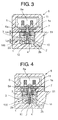
- FIG.3 is a drawing for explaining the relation between the stroke of the poppet valve and the movable range of spherical bodies received in the inside space 1a of the poppet valve in the first embodiment shown in FIG. 1.
- the distance (Ls) of movement of the mass objects 10 in the inside space 1a in the axial direction of the poppet valve is defined to be equal to or smaller than the stroke (Lp) of reciprocation of the poppet valve, i.e. (Ls ⁇ Lp) as shown in FIG.3.
- the vibration system consisting of attraction force of the solenoid device 6, the mass of the poppet valve 1 including the armature 5, spring force of the poppet valve spring 5a, and spring constant at the seat portion 4 of the valve seat member 2 begins to vibrate and bouncing of the poppet valve 1 repeats, that is, bounce vibration occurs.
- the spherical bodies 10 is allowed to reciprocate more than once in the inside space 1a by composing such that Ls ⁇ Lp, and can exert inertia force to the poppet valve 1 in the direction opposite to the vibration direction of the poppet valve bounce vibration and the bounce vibration can be restrained.
- the spherical bodies 10 received in the inside space 1a of the poppet valve 1 are solid bodies, they can be inserted easily into the inside space 1a, fear of spilling of them from the inside space 1a when inserting them or during operation of the engine is eliminated, handling is easy, and safety is increased.
- FIG.2 is a drawing of the second embodiment corresponding to FIG. 1.
- a plurality of needle bodies 15 are received in the inside space 1a of the poppet valve 1 instead of the spherical bodies 10.
- Each of the needle bodies 15 is of needle-like or bar-like shape made of steel, rubber, or plastic material, and a plurality of them are received in the inside space 1a movably in the axial direction 1b of the poppet valve 1 and capably of contacting with each other on their outer surfaces.
- the number of collision of the needle-like bodies against the poppet valve in the axial direction can be increased compared to the case of spherical bodies in which the spherical bodies collide with each other in the axial direction. Further, contacting portion increases and friction resistance when the needle-like bodies move in the inside space 1a of the poppet valve 1 can be increased.
- the time the needle bodies 15 collide against the upper end or lower end of the inside space 1a can be optimized for restraining rebounding of the poppet valve when it sits on the seat portion 4 of the valve seat member 2 or sits on the seat face of the injector body 51 as mentioned in the explanation of the first invention.
- Other construction is the same as that of the first embodiment of FIG. 1, and components members same as those of FIG. 1 are designated with the same reference numerals.
- FIG.4 is a drawing of the third embodiment corresponding to FIG.1
- FIG.5 is a drawing for explaining the relation between the stroke of the poppet valve and the movable range of spherical bodies received inside the poppet valve in the third embodiment shown in FIG.4,
- FIG.6 is an enlarged detail of the part indicated with an arrow Z in the third embodiment shown in FIG.4 and FIG.5.
- a plurality of spherical bodies 10 are received in an inside space 1a of a poppet valve 1 so that they can move axially therein contacting with each other when the poppet valve 1 reciprocates the same as is in the first embodiment, and a small hole 13 is provided in a plug 12 plugging the inside space 1a through which the inside space 1a is communicated to an outside fuel passage, i.e. a passage near the poppet valve 1.
- fuel can flow into or out from the inside space 1a of the poppet valve 1 through the small hole 13 allowing the inside space 1a to communicate to the outside fuel passage, thus a dash pot function is realized, so the bouncing of the poppet valve 1 can be restrained by the damping effect of the dash pot function.
- the spherical bodies 10 perform to restrain bouncing of the poppet valve by inertia force similarly as is done in the first embodiment.
- the distance (Ls) of movement of the mass objects in the inside space, where fuel oil can flow into or out from through the small hole, in the axial direction of the poppet valve is defined to be equal to or smaller than the stroke(Lp) of reciprocation of the poppet valve, i.e. (Ls ⁇ Lp) as shown in FIG.5.
- FIG.5 components members same as those of FIG.4 are designated with the same reference numerals.
- effect of restraining bouncing is further increased by being doubly effected by the damping effect of the dash pot function and the bounce restraining effect of the inertia force of the mass objects.
- the spherical bodies 10 received in the inside space 1a can be replaced by the needle bodies 15 of the second embodiment.
- bouncing can be restrained only by the dash pot function without receiving in the inside space 1a the spherical bodies 10 or needle bodies 15.
- an electronic controlled fuel injection apparatus composed to control the fuel injection at the beginning and end of the injection by the reciprocation of the poppet valve improved in safety and eased in handling can be provided, in which effect of preventing or restraining bouncing of the poppet valve is increased by utilizing inertia and friction force arising from the reciprocating moving of the poppet valve.
Landscapes
- Engineering & Computer Science (AREA)
- Chemical & Material Sciences (AREA)
- Combustion & Propulsion (AREA)
- Mechanical Engineering (AREA)
- General Engineering & Computer Science (AREA)
- Fuel-Injection Apparatus (AREA)
Abstract
Description
- The present invention relates to an electromagnetic controlled fuel injection apparatus applied to an electromagnetic controlled unit injector, etc. for a diesel engine and composed such that fuel injection timing thereof is controlled by means of a poppet valve which is reciprocated by means of a solenoid device to open or close the passage between the fuel passage to the plunger room where fuel is received and compressed to high pressure and the spill passage to the fuel return line.
- An electromagnetic controlled unit injector applied to a diesel engine is composed such that fuel injection timing is controlled through shutting-off/allowing communication of a fuel passage, which connects to a plunger room where fuel is introduced and compressed to high pressure, with a spill passage connecting to a fuel return line by closing/opening a poppet valve reciprocated by a solenoid device and a poppet valve spring.
Injection of fuel begins when the poppet valve sits on the seat portion of the valve seat and ends when the poppet valve leaves the seat portion. There is a problem that a bounce of the poppet valve occurs when the poppet valve sits on the seat portion of the valve seat or when the poppet valve sits on the bottom seat face of the injector body, that is, the poppet valve rebounds from the seat portion at the beginning of the injection and rebounds from the bottom seat face of the injector body at the end of the injection, which causes irregular fuel injection at the start and end of injection. - A means to prevent the occurrence of valve bounce is disclosed in JP5-223031A(US005284302).
- According to the disclosure, in an electromagnetic fuel injection valve, a magnetic powder of a specified mass is received in a sealed inside space formed inside the needle valve axially movably therein. The magnetic powder which is an inertial collision element moves in the inside space by inertia force generated by the move of the needle valve and collide against the undersurface of a plug screwed in the upper part of the inside space of the needle valve or against the bottom face of the inside space, and the occurrence of bounce of the needle valve when needle valve sits on the stopper plate in the upper part or on the valve seat portion in the lower part is restrained, and the durability of the electromagnetic fuel injection valve is improved.
- However, with the art disclosed in JP5-223031A(US005284302), the magnetic powder is received in an enclosed space inside the needle valve and the magnetic powder is allowed to move in the enclosed space by the inertia force to collide against the undersurface of a plug screwed in the upper part of the inside space of the needle valve, so there is a risk that the magnetic powder leaks out of the inside space when enclosing it in the inside space or the magnetic powder leaks through the gap in the screwed part of the screw plug and mixes in the fuel resulting in jeopardizing safe and stable operation of the engine.
- Further, when magnetic substance is used for the valve body of the electromagnetic valve, original magnetic flux is disturbed, attraction may change, and there may happen that the magnetic substance does not contact the bolt when bouncing if the magnetic substance is attracted by the magnetic force of the solenoid. When the magnetic substance rebounds, it does not collide with the bolt, and bounce restraining effect does not result.
- When nonmagnetic solid substance is used, influence by magnetic force does not occur when it is used as an electromagnetic valve. However, in order to allow it to collide with the needle valve with a specified time lag, matching of the distance of movement, orifice diameter, spring force of the spring(31), mass of the piston is necessary. As to the move of the needle valve, there may be a case where the direction of the move of the needle valve changes halfway from opening direction to closing direction or vice versa and the needle valve moves between the seat position and the midway of its lift when bouncing repeats, so there is a possibility of a change in the distance of motion of the inertial collision element.
Further, it is expected that the bounce is restrained to a single collision of the inertial collision element such as the magnetic powder and to cope with repetition of bounce is not accepted. - Particularly, it is effective to inject fuel in numbers to meet exhaust emission regulation, and when the electromagnetic valve is energized again immediately after the first injection in multistage injection, the position of the inertial collision element in the inside space of the needle valve varies according to conditions.
- The object of the present invention is to provide an electromagnetic controlled fuel injection apparatus with a poppet valve of which the beginning and end of fuel injection is controlled by the reciprocation of the poppet valve, in which inertia force and friction force due to the reciprocating motion of the poppet valve are utilized effectively to suppress the bounce of the poppet valve.
- To attain the object, the present invention proposes an electromagnetic controlled fuel injection apparatus with a poppet valve composed such that the beginning and end of fuel injection is controlled by opening and closing a passage connecting to a fuel passage communicating to a plunger room where fuel is compressed to high pressure by a plunger and to a spill passage communicating to a fuel return line by means of a poppet valve reciprocated by a solenoid device and a poppet valve spring, wherein the poppet valve has a sealed inside space, and a plurality of mass objects are received in the inside space so that the mass objects can move while contacting with each other in the inside space due to inertia force generated by the reciprocating motion of the poppet valve.
- In the invention, it is preferable that the mass objects are received in the inside space of the poppet valve together with liquid such as fuel or lubrication oil.
- In the invention, it is preferable that the mass objects are spherical bodies made of material including metal.
- According to the invention, as a plurality of spherical bodies such as steel balls are received axially movably in the enclosed
space 1a provided inside thepoppet valve 1 reciprocated by the solenoid device and poppet valve spring, the spherical bodies exert inertia force to the poppet valve in the direction opposite to bouncing direction of the poppet valve by colliding against an end of the inside space of the poppet valve when the poppet valve sits on the seat portion of the valve seat member or sits on the seat face of the injector body and begins rebounding. - It is necessary that there is a time lag between the sitting of the poppet valve and the collision of the mass objects.
- By receiving a plurality of mass objects in the inside space, stochastically several of the mass objects collide with the poppet valve in the inside space irrespective of the positions of the mass objects in the inside space.
- Further, by receiving liquid such as fuel, lube oil in the inside space of the poppet valve together with the mass objects, resistance to the move of the mass objects in the inside space of the poppet valve can be adjusted, and the mass objects can be allowed to collide against an end of the inside space at the time the rebounding of the poppet valve is restrained most effectively.
- Therefore, the occurrence of irregular injection beginning and end, variation of injection quantity, and irregular injection resulting from the bouncing of the poppet valve can be positively prevented.
- Further, as the mass objects received in the inside space of the poppet valve are solid bodies such as spherical bodies, they can be inserted easily into the inside space, fear of spilling of them from the inside space when inserting them or during operation of the engine is eliminated, handling is easy, and safety is increased.
In the invention, it is preferable that the distance (Ls) of movement of the mass objects in the inside space in the axial direction of the poppet valve is defined to be equal to or smaller than the stroke(Lp) of reciprocation of the poppet valve, i.e. (Ls≦Lp).
With the configuration, the mass objects contact without fail an opposite side end of the inside space opposite to the moving direction of the poppet valve and moves together with the poppet valve, and the mass objects can be allowed to collide against the other side end of the inside space to exert inertia force in the direction in which it restrains the rebounding of the poppet valve when it sits on the seat face of the injector body. Further, when the rebound is not completely prevented and repetition of bounces i.e. bounce vibration occurs, the bounce vibration can be attenuated by reciprocation of the mass objects in the inside space.
In the invention, it is preferable that the mass objects are needle-like bodies made of material including metal.
With this composition, as the mass objects received in the inside space are needle-like bodies, contacting portion of them increases and friction resistance when the needle-like bodies move in the inside space of the poppet valve can be increased, and the range of adjustment of resistance for the needle-like bodies in the inside space so that the needle-like bodies collide against an end of the inside space at the time optimal to restrain bouncing of the poppet valve can be increased. - It is also suitable that the electromagnetic controlled fuel injection apparatus is composed such that the poppet valve has an inside space, and a small hole is provided at an end or at each of both ends of the inside space to communicate the inside space to an outside fuel passage, whereby fuel is allowed to flow in or out of the inside space through the small hole by the reciprocating motion of the poppet valve.
- According to the invention, as dash pot function is performed by the flowing of fuel into or out of the inside space of the poppet valve through the small hole in correspondence with the reciprocation of the poppet valve, bouncing of the poppet valve from the seat after it sits on the seat can be restrained by the dash pot function.
- By combining the means to restrain the bouncing by the dash pot function and the means to restrain bouncing by the inertia force of the mass objects, that is, by receiving a plurality of mass objects axially movably while contacting with each other in the inside space of the poppet valve composed to have dash pot function, effect of restraining bouncing is further increased by being doubly effected by the damping effect of the dash pot function and the bounce restraining effect of the inertia force of the mass objects.
- In the invention, it is preferable that the distance(Ls) of movement of the mass objects in the inside space, where fuel oil can flow into or out from through the small hole, in the axial direction of the poppet valve is defined to be equal to or smaller than the stroke (Lp) of reciprocation of the poppet valve, i.e. (Ls≦Lp).
With the configuration, bouncing can be prevented or restrained when the poppet valve sits on the seat portion of the valve seat member or sits on the seat face of the injector body.
Further, when the rebound is not completely prevented and repetition of bounces i.e. bounce vibration occurs, the bounce vibration can be attenuated by reciprocation of the mass objects in the inside space.
According to the present invention, inertia force of several of a plurality of the mass objects can be exerted in the direction contrary to the bouncing direction at optimal timing to prevent or restrain the bouncing of the poppet valve irrespective or regardless of the positions of the mass objects in the inside space. Therefore, bouncing of the poppet valve can be effectively prevented or restrained in a wide range of operation compared to the prior art with which bouncing is restrained under a definite condition, and the occurrence of irregular injection at the beginning and end of the injection, variation of injection quantity, and irregular injection resulting from the bouncing of the poppet valve can be prevented.
Further, as the mass objects received in the inside space of the poppet valve are solid bodies such as spherical bodies, they can be inserted easily into the inside space, fear of spilling of them from the inside space when inserting them or during operation of the engine is eliminated, handling is easy, and safety is increased. - Further, according to the invention, the apparatus is composed such that a dash pot function is performed by the flowing of fuel into or out of the inside space of the poppet valve through the small hole in correspondence with the reciprocation of the poppet valve, bouncing of the poppet valve from the seat after it sits on the seat can be restrained by the dash pot function.
-
- FIG. 1 is a sectional view of the substantial part of the first embodiment of the electromagnetic open/close valve with a poppet valve of an electromagnetic controlled unit injector for a diesel engine according to the present invention.
- FIG.2 is a drawing of the second embodiment corresponding to FIG. 1.
- FIG.3 is a drawing for explaining the relation between the stroke of the poppet valve and the movable range of spherical bodies received inside the poppet valve in the first embodiment shown in FIG. 1.
- FIG.4 is a drawing of the third embodiment corresponding to FIG. 1.
- FIG. 5 is a drawing for explaining the relation between the stroke of the poppet valve and the movable range of spherical bodies received inside the poppet valve in the third embodiment shown in FIG.4.
- FIG.6 is an enlarged detail of the part indicated with an arrow Z in the third embodiment shown in FIG.4, 5.
- FIG.7 is a longitudinal sectional view of an electromagnetic controlled unit injector for a diesel engine to which the present invention is applied.
- A preferred embodiment of the present invention will now be detailed with reference to the accompanying drawings. It is intended, however, that unless particularly specified, dimensions, materials, relative positions and so forth of the constituent parts in the embodiments shall be interpreted as illustrative only not as limitative of the scope of the present invention.
- FIG.7 is a longitudinal sectional view of an electromagnetic controlled unit injector for a diesel engine to which the present invention is applied.
- In FIG.7,
reference numeral 50 is an electromagnetic controlled unit injector.Reference numeral 51 is an injector body, 7 is a plunger provided reciprocatably in theinjector body plunger plunger injection holes 52a from which the high pressure fuel in theplunger room 8 is injected into the combustion chamber of an engine not shown in the drawing, 53 is a needle valve provided reciprocatably in thefuel injection nozzle needle valve 53. -
Reference numeral 100 is an electromagnetic valve device composed as follows: -
Reference numeral 1 is a poppet valve, 2 is a valve seat member in which thepoppet valve 1 is inserted reciprocatably, 5a is a poppet vale spring, 2b is a fuel passage communicating to thefuel passage 9 in theinjector body -
Reference numeral 6 is a solenoid device having aelectromagnetic coil poppet valve 1 which can be attracted to be lifted upward by theelectromagnetic coil 6a. - In operation of a diesel engine equipped with the electromagnetic controlled
unit injector 50, fuel is introduced into theplunger room 8 and compressed therein by the reciprocation of theplunger 7 driven by a fuel cam of the engine not shown in the drawing by the medium of thetappet 56 and tappetspring 55. - When the
armature 5 fixed to thepoppet valve 1 of theelectromagnetic valve device 100 is attracted toward theelectromagnetic coil 6a of thesolenoid device 6 upon excitation of thesolenoid device 6, thepoppet valve 1 is seated onto theseat portion 4 of thevalve seat member 2 to close the poppet valve, and the fuel pressure in theplunger room 8, in thefuel passage 2b, in theelectromagnetic valve device 100, in theplunger room 8, in thepassage 9 in theinjector body 51, and in the fuel passage communicating to afuel pool 52 increases as theplunger 7 moves down. - When the fuel pressure exceeds the opening pressure of the
needle valve 53, theneedle valve 53 opens and high pressure fuel is injected from theinjection hole 52a into the combustion chamber not shown in the drawing. - When the excitation of the
solenoid device 6 is released, thearmature 5 moves down pushed by thepoppet valve spring 5a, thepoppet valve 1 leaves theseat portion 4 of thevalve seat member 2, a seat passage is formed between the poppet valve and valve seat member, and the fuel in theplunger room 7 is discharged through thefuel passage spill passage 3. - The present invention relates to an improvement of the electromagnetic open/
close valve device 100 of an electromagnetic controlled fuel injection apparatus such as an electromagnetic controlledfuel injector 50. - FIG.1 is a sectional view of the substantial part of the first embodiment of the electromagnetic open/close valve with a poppet valve of an electromagnetic controlled unit injector for a diesel engine according to the present invention.
- Referring to FIG. 1,
reference numeral 6 is a solenoid device, 6a is a electromagnetic coil of the solenoid device, 1 is a poppet valve, 5a is a poppet valve spring, 2 is a valve seat member in which thepoppet valve 1 is fitted reciprocatably, 4 indicates the seat portion where thepoppet valve 1 sits on.
Thepoppet valve 1 is reciprocated by the attraction ofsolenoid device 6 and the spring force of thepoppet valve spring 5a.Reference numeral 2a is a fuel pool communicating to afuel passage valve seat member 2. -
Reference numeral 5 is an armature fixed to the upper end of thepoppet valve 1, the armature can be attracted by theelectromagnetic coil 6a. -
Reference numeral 1a is an inside space formed inside thepoppet valve 1 to extend along thecenter axis 1b of the poppet valve. Theinside space 1a is substantially an enclosed space closed with a fixingbolt 11 for fixing thearmature 5 at the upper side thereof and closed with aplug 12 at the lower side thereof. -
Reference numeral 10 is a plurality of spherical bodies received in theinside space 1a. Thespherical bodies 10 may be steel balls, rubber balls, or plastic balls. Thespherical bodies 10 are received in theinside space 1a so that they can move axially therein contacting with each other when thepoppet valve 1 reciprocates. - In the first embodiment, as a plurality of
spherical bodies 10 such as steel balls are received axially movably in theenclosed space 1a provided inside thepoppet valve 1 reciprocated by thesolenoid device 6 andpoppet valve spring 5a, when thesolenoid device 6 is excited and thepoppet valve 1 is moved upward at the injection beginning and thepoppet valve 1 sits on theseat portion 4 of thevalve seat member 2 and stops upward moving, thespherical bodies 10 received axially movably in theinside space 1a of thepoppet valve 1 continue upward moving and some of thespherical bodies 10 collides against the upper end of theinside space 1a, i.e. the lower end of the fixingbolt 11, and exerts upward force to thepoppet valve 1 at the beginning of rebound of thepoppet valve 1 to push it up to counteract the downward rebounding force thereof. - The downward rebound of the poppet valve occurs some time after it sits on the
seat portion 4 of thevalve member 2, so it is necessary that the spherical bodies collides against the upper end of theinside space 1a at the time optimal for restraining the rebound of thepoppet valve 1 some time after the poppet valve sits on the seat portion. The time from the departure of the spherical bodies from the lower end of theinside space 1a when thepoppet valve 1 sits on theseat portion 4 of thevalve seat member 2 until the collision against the upper end of theinside space 1a differs according to velocity of the spherical bodies and distance of move thereof in theinside space 1a, and the velocity is influenced by the resistance against the move of the spherical bodies in theinside space 1a and the distance of move also changes according to operating conditions.
Therefore, it is possible to make the number of the spherical bodies that collide against the poppet valve stochastically constant by receiving a plurality of the spherical bodies in the inside space in spite of change in the resistance and operating conditions. Stable bounce restraining effect can be attained through achieving nearly constant probability of collision of the spherical bodies against the poppet valve by increasing the number of the spherical bodies. Further, the probability of the collision can be adjusted by receiving the spherical bodies in theinside space 1a together with fuel or lube oil or by a method described in the second embodiment explained later. - FIG.3 is a drawing for explaining the relation between the stroke of the poppet valve and the movable range of spherical bodies received in the
inside space 1a of the poppet valve in the first embodiment shown in FIG. 1. - In the first embodiment, it is preferable that the distance (Ls) of movement of the mass objects 10 in the
inside space 1a in the axial direction of the poppet valve is defined to be equal to or smaller than the stroke (Lp) of reciprocation of the poppet valve, i.e. (Ls≦Lp) as shown in FIG.3. - In this case, when the
poppet valve 1 leaves the seat portion of thevalve seat member 2 and moves downward, at least one of the spherical bodies comes into contact with the upper end of theinside space 1a without fail and moves downward together with thepoppet valve 1, so the rebound when the bottom face of thepoppet valve 1 sits on the seat face in theinjector body 51 is restrained similarly as it is when thepoppet valve 1 sits on theseat portion 4 of thevalve seat member 2. Further, when downward bouncing force is not completely counteracted and bouncing occurs, the vibration system consisting of attraction force of thesolenoid device 6, the mass of thepoppet valve 1 including thearmature 5, spring force of thepoppet valve spring 5a, and spring constant at theseat portion 4 of thevalve seat member 2 begins to vibrate and bouncing of thepoppet valve 1 repeats, that is, bounce vibration occurs. When the bounce vibration occurs, thespherical bodies 10 is allowed to reciprocate more than once in theinside space 1a by composing such that Ls ≦Lp, and can exert inertia force to thepoppet valve 1 in the direction opposite to the vibration direction of the poppet valve bounce vibration and the bounce vibration can be restrained. - In FIG.3, component members same as those of FIG. 1 are designated with the same reference numerals.
- As has been described above, according to the first invention, rebounding of the
poppet valve 1 when it sits on theseat portion 4 of thevalve seat member 2 and on the seat face of theinjector body 51 is restrained, and the occurrence of irregular injection beginning and end, variation of injection quantity, and irregular injection resulting from the bouncing of the poppet valve can be positively prevented. - Further, as the
spherical bodies 10 received in theinside space 1a of thepoppet valve 1 are solid bodies, they can be inserted easily into theinside space 1a, fear of spilling of them from theinside space 1a when inserting them or during operation of the engine is eliminated, handling is easy, and safety is increased. - Further, it is possible to compose such that the spherical bodies are received in the inside space of the poppet valve together with liquid such as fuel or lubrication oil.
- With this, by filling liquid such as fuel or lubrication oil in the
inside space 1a together with the spherical bodies, effect of restraining the rebound can be optimized by adjusting the resistance to the move of the spherical bodies in theinside space 1a of thepoppet valve 1 as mentioned before. - FIG.2 is a drawing of the second embodiment corresponding to FIG. 1.
- In the second embodiment, a plurality of
needle bodies 15 are received in theinside space 1a of thepoppet valve 1 instead of thespherical bodies 10. Each of theneedle bodies 15 is of needle-like or bar-like shape made of steel, rubber, or plastic material, and a plurality of them are received in theinside space 1a movably in theaxial direction 1b of thepoppet valve 1 and capably of contacting with each other on their outer surfaces. - Other construction is the same as that of the first embodiment of FIG.1, and components members same as those of FIG.1 are designated with the same reference numerals.
- According to the second embodiment, as the
needle bodies 15 received in theinside space 1a of thepoppet valve 1 are of needle-like or bar-like shape, the number of collision of the needle-like bodies against the poppet valve in the axial direction can be increased compared to the case of spherical bodies in which the spherical bodies collide with each other in the axial direction. Further, contacting portion increases and friction resistance when the needle-like bodies move in theinside space 1a of thepoppet valve 1 can be increased. Accordingly, and by these two effects, the time theneedle bodies 15 collide against the upper end or lower end of theinside space 1a can be optimized for restraining rebounding of the poppet valve when it sits on theseat portion 4 of thevalve seat member 2 or sits on the seat face of theinjector body 51 as mentioned in the explanation of the first invention.
Other construction is the same as that of the first embodiment of FIG. 1, and components members same as those of FIG. 1 are designated with the same reference numerals. - FIG.4 is a drawing of the third embodiment corresponding to FIG.1, FIG.5 is a drawing for explaining the relation between the stroke of the poppet valve and the movable range of spherical bodies received inside the poppet valve in the third embodiment shown in FIG.4, and FIG.6 is an enlarged detail of the part indicated with an arrow Z in the third embodiment shown in FIG.4 and FIG.5.
- According to the third embodiment, a plurality of
spherical bodies 10 are received in aninside space 1a of apoppet valve 1 so that they can move axially therein contacting with each other when thepoppet valve 1 reciprocates the same as is in the first embodiment, and asmall hole 13 is provided in aplug 12 plugging theinside space 1a through which theinside space 1a is communicated to an outside fuel passage, i.e. a passage near thepoppet valve 1. - Other construction is the same as that of the first embodiment of FIG. 1, and components members same as those of FIG. 1 are designated with the same reference numerals.
- In the third embodiment, fuel can flow into or out from the
inside space 1a of thepoppet valve 1 through thesmall hole 13 allowing theinside space 1a to communicate to the outside fuel passage, thus a dash pot function is realized, so the bouncing of thepoppet valve 1 can be restrained by the damping effect of the dash pot function. - In this case also the
spherical bodies 10 perform to restrain bouncing of the poppet valve by inertia force similarly as is done in the first embodiment. - In the third embodiment, it is preferable that the distance (Ls) of movement of the mass objects in the inside space, where fuel oil can flow into or out from through the small hole, in the axial direction of the poppet valve is defined to be equal to or smaller than the stroke(Lp) of reciprocation of the poppet valve, i.e. (Ls≦Lp) as shown in FIG.5.
- The effect is the same as described in the first embodiment.
- In FIG.5, components members same as those of FIG.4 are designated with the same reference numerals.
- As described above, according to the third embodiment, by combining the construction having dash pot function by providing the
small hole 13 to allow communication of theinside space 1a of thepoppet valve 1 to the outside fuel passage with the construction of the first embodiment to restrain bouncing by means ofspherical bodies 10, effect of restraining bouncing is further increased by being doubly effected by the damping effect of the dash pot function and the bounce restraining effect of the inertia force of the mass objects. - The
spherical bodies 10 received in theinside space 1a can be replaced by theneedle bodies 15 of the second embodiment. - Further, bouncing can be restrained only by the dash pot function without receiving in the
inside space 1a thespherical bodies 10 orneedle bodies 15. - According to the present invention, an electronic controlled fuel injection apparatus composed to control the fuel injection at the beginning and end of the injection by the reciprocation of the poppet valve improved in safety and eased in handling can be provided, in which effect of preventing or restraining bouncing of the poppet valve is increased by utilizing inertia and friction force arising from the reciprocating moving of the poppet valve.
Claims (8)
- An electromagnetic controlled fuel injection apparatus with a poppet valve (1) composed such that the beginning and end of fuel injection is controlled by opening and closing a passage connecting to a fuel passage (9) communicating to a plunger room (8) where fuel is compressed to high pressure by a plunger (7)and to a spill passage (3) communicating to a fuel return line by means of a poppet valve reciprocated by a solenoid device (6) and a poppet valve spring (5a), characterized in that said poppet valve has a sealed inside space (1a), and a plurality of mass objects (10, 15) are received in said inside space so that the mass objects can move while contacting with each other in said inside space due to inertia force generated by the reciprocating motion of said poppet valve.
- An electromagnetic controlled fuel injection apparatus with a poppet valve (1) according to claim 1, characterized in that the distance(Ls) of movement of said mass objects (10, 15) in said inside space (1a) in the axial direction of the poppet valve is defined to be equal to or smaller than the stroke (Lp) of reciprocation of the poppet valve, i.e. (Ls ≦Lp).
- An electromagnetic controlled fuel injection apparatus with a poppet valve (1) according to any one of claims 1-2, characterized in that said mass objects (10, 15) are received in the inside space (1a) of said poppet valve together with liquid such as fuel or lubrication oil.
- An electromagnetic controlled fuel injection apparatus with a poppet valve (1) according to any one of claim 1-3, characterized in that said mass objects are spherical bodies (10) made of material including metal.
- An electromagnetic controlled fuel injection apparatus with a poppet valve (1) according to any one of claim 1-3, characterized in that said mass objects are needle-like bodies (15) made of material including metal.
- An electromagnetic controlled fuel injection apparatus with a poppet valve (1) composed such that the beginning and end of fuel injection is controlled by opening and closing a passage connecting to a fuel passage (9) communicating to a plunger room (18) where fuel is compressed to high pressure by a plunger (7) and to a spill passage (3) communicating to a fuel return line by means of a poppet valve reciprocated by a solenoid device (6) and a poppet valve spring (5a), characterized in that said poppet valve has an inside space, and a small hole (13) is provided at an end or at each of both ends of said inside space to communicate said inside space (1a) to an outside fuel passage, whereby fuel is allowed to flow in or out of said inside space through said small hole by the reciprocating motion of said poppet valve.
- An electromagnetic controlled fuel injection apparatus with a poppet valve (1) according to claim 6, characterized in that a plurality of mass objects (10, 15) are received in said inside space (1a) so that the mass objects can move while contacting with each other in said inside space due to inertia force generated by the reciprocating motion of said poppet valve.
- An electromagnetic controlled fuel injection apparatus with a poppet valve (1) according to claim 7, characterized in that the distance (Ls) of movement of said mass objects (10, 15) in said inside space (1a), where fuel oil can flow into or out from through said small hole (13), in the axial direction of the poppet valve is defined to be equal to or smaller than the stroke(Lp) of reciprocation of the poppet valve, i.e. (Ls≦Lp) .
Applications Claiming Priority (2)
| Application Number | Priority Date | Filing Date | Title |
|---|---|---|---|
| JP2005049304 | 2005-02-24 | ||
| JP2005334725A JP4634285B2 (en) | 2005-02-24 | 2005-11-18 | Electromagnetic control fuel injection device with poppet valve |
Publications (2)
| Publication Number | Publication Date |
|---|---|
| EP1703120A1 true EP1703120A1 (en) | 2006-09-20 |
| EP1703120B1 EP1703120B1 (en) | 2008-11-12 |
Family
ID=36084414
Family Applications (1)
| Application Number | Title | Priority Date | Filing Date |
|---|---|---|---|
| EP20060110374 Ceased EP1703120B1 (en) | 2005-02-24 | 2006-02-24 | Electromagnetic controlled fuel injection apparatus with poppet valve |
Country Status (5)
| Country | Link |
|---|---|
| US (1) | US7350539B2 (en) |
| EP (1) | EP1703120B1 (en) |
| JP (1) | JP4634285B2 (en) |
| AT (1) | ATE414224T1 (en) |
| DE (1) | DE602006003581D1 (en) |
Cited By (1)
| Publication number | Priority date | Publication date | Assignee | Title |
|---|---|---|---|---|
| EP2363592A1 (en) * | 2010-02-25 | 2011-09-07 | Continental Automotive GmbH | Injection valve |
Families Citing this family (6)
| Publication number | Priority date | Publication date | Assignee | Title |
|---|---|---|---|---|
| JP4227965B2 (en) * | 2005-02-28 | 2009-02-18 | 三菱重工業株式会社 | Electromagnetic control fuel injection device |
| JP2008045486A (en) * | 2006-08-16 | 2008-02-28 | Yanmar Co Ltd | Accumulator fuel injection device |
| JP4719140B2 (en) * | 2006-12-20 | 2011-07-06 | 三菱重工業株式会社 | Electromagnetic valve device and fuel injection device for an engine equipped with the same |
| DE102009006987B3 (en) * | 2009-01-31 | 2010-09-30 | Deutsches Zentrum für Luft- und Raumfahrt e.V. | magnetic valve |
| US7942349B1 (en) | 2009-03-24 | 2011-05-17 | Meyer Andrew E | Fuel injector |
| US11118698B2 (en) * | 2018-07-23 | 2021-09-14 | Pratt & Whiiney Canada Corp. | Damping mechanism for valves |
Citations (8)
| Publication number | Priority date | Publication date | Assignee | Title |
|---|---|---|---|---|
| US5284302A (en) * | 1992-02-12 | 1994-02-08 | Nippondenso Co., Ltd. | Fuel injection valve |
| US5427352A (en) * | 1993-09-22 | 1995-06-27 | Robert Bosch Gmbh | Electromagnetic valve |
| US5443209A (en) * | 1994-08-02 | 1995-08-22 | Diesel Technology Company | High pressure diesel fuel injector for internal combustion engines |
| WO1999009318A1 (en) * | 1997-08-15 | 1999-02-25 | Diesel Technology Company | Improved fuel pump control valve assembly |
| US6021999A (en) * | 1998-08-11 | 2000-02-08 | Caterpillar Inc. | Bounce suppression device for high speed poppet valve |
| US6109541A (en) * | 1998-07-23 | 2000-08-29 | Caterpillar Inc. | Apparatus for reducing the bounce of a poppet valve |
| EP1371842A1 (en) * | 2002-06-11 | 2003-12-17 | General Motors Corporation | Anti-bounce needle valve for a fuel injector |
| US20040195349A1 (en) * | 2002-07-16 | 2004-10-07 | Robert Bosch Fuel Systems Corporation | Fuel injector control module with unidirectional dampening |
Family Cites Families (7)
| Publication number | Priority date | Publication date | Assignee | Title |
|---|---|---|---|---|
| US455913A (en) * | 1891-07-14 | Means for equalizing the pressure of gas in gas service-pipes | ||
| US4566485A (en) * | 1984-11-19 | 1986-01-28 | Ruhle James L | Free-floating neutrally-buoyant reciprocating pump valve for abrasive fluids |
| US5392811A (en) * | 1993-11-02 | 1995-02-28 | Caterpillar Inc. | High pressure fuel system valve |
| US5984259A (en) * | 1997-11-26 | 1999-11-16 | Saturn Electronics & Engineering, Inc. | Proportional variable force solenoid control valve with armature damping |
| DE19820341C2 (en) * | 1998-05-07 | 2000-04-06 | Daimler Chrysler Ag | Actuator for a high pressure injector for liquid injection media |
| US6145805A (en) * | 1999-08-23 | 2000-11-14 | Caterpillar Inc. | Liquid control valve assembly with local damping and hydraulically actuated fuel injector using same |
| JP2002098024A (en) * | 2000-09-26 | 2002-04-05 | Mitsubishi Heavy Ind Ltd | Electronically controlled fuel injection system |
-
2005
- 2005-11-18 JP JP2005334725A patent/JP4634285B2/en not_active Expired - Fee Related
-
2006
- 2006-02-23 US US11/359,435 patent/US7350539B2/en not_active Expired - Lifetime
- 2006-02-24 AT AT06110374T patent/ATE414224T1/en not_active IP Right Cessation
- 2006-02-24 DE DE200660003581 patent/DE602006003581D1/en not_active Expired - Fee Related
- 2006-02-24 EP EP20060110374 patent/EP1703120B1/en not_active Ceased
Patent Citations (8)
| Publication number | Priority date | Publication date | Assignee | Title |
|---|---|---|---|---|
| US5284302A (en) * | 1992-02-12 | 1994-02-08 | Nippondenso Co., Ltd. | Fuel injection valve |
| US5427352A (en) * | 1993-09-22 | 1995-06-27 | Robert Bosch Gmbh | Electromagnetic valve |
| US5443209A (en) * | 1994-08-02 | 1995-08-22 | Diesel Technology Company | High pressure diesel fuel injector for internal combustion engines |
| WO1999009318A1 (en) * | 1997-08-15 | 1999-02-25 | Diesel Technology Company | Improved fuel pump control valve assembly |
| US6109541A (en) * | 1998-07-23 | 2000-08-29 | Caterpillar Inc. | Apparatus for reducing the bounce of a poppet valve |
| US6021999A (en) * | 1998-08-11 | 2000-02-08 | Caterpillar Inc. | Bounce suppression device for high speed poppet valve |
| EP1371842A1 (en) * | 2002-06-11 | 2003-12-17 | General Motors Corporation | Anti-bounce needle valve for a fuel injector |
| US20040195349A1 (en) * | 2002-07-16 | 2004-10-07 | Robert Bosch Fuel Systems Corporation | Fuel injector control module with unidirectional dampening |
Cited By (1)
| Publication number | Priority date | Publication date | Assignee | Title |
|---|---|---|---|---|
| EP2363592A1 (en) * | 2010-02-25 | 2011-09-07 | Continental Automotive GmbH | Injection valve |
Also Published As
| Publication number | Publication date |
|---|---|
| JP2006266254A (en) | 2006-10-05 |
| EP1703120B1 (en) | 2008-11-12 |
| DE602006003581D1 (en) | 2008-12-24 |
| US7350539B2 (en) | 2008-04-01 |
| US20060185650A1 (en) | 2006-08-24 |
| ATE414224T1 (en) | 2008-11-15 |
| JP4634285B2 (en) | 2011-02-16 |
Similar Documents
| Publication | Publication Date | Title |
|---|---|---|
| KR100347430B1 (en) | Collision Relief Amateur and Needle Valve Assembly | |
| EP1045135B1 (en) | Fuel-injection valve | |
| EP0851114B1 (en) | Perfected electromagnetic metering valve for a fuel injector | |
| EP2336544A1 (en) | Anti-bounce mechanism for fuel injectors | |
| KR102301677B1 (en) | Fuel injector | |
| EP1602821A1 (en) | Fuel injection valve | |
| US5967413A (en) | Damped solenoid actuated valve and fuel injector using same | |
| EP1801409B1 (en) | Fuel injector | |
| EP1703120B1 (en) | Electromagnetic controlled fuel injection apparatus with poppet valve | |
| JP2004519609A (en) | Solenoid valve for controlling the injection valve of an internal combustion engine | |
| US6702207B2 (en) | Fuel injector control module with unidirectional dampening | |
| US5284302A (en) | Fuel injection valve | |
| KR20230028755A (en) | solenoid valve | |
| JP2004511718A (en) | Magnet valve for controlling the injection valve of an internal combustion engine | |
| JP2006266254A5 (en) | ||
| US6196199B1 (en) | Fuel injector assembly having an improved solenoid operated check valve | |
| KR20200103716A (en) | Fluid metering valve | |
| US7467781B2 (en) | Poppet valve device and electronic controlled fuel injection apparatus equipped with the device | |
| US20180195477A1 (en) | Valve for metering a fluid | |
| KR102706035B1 (en) | Valve for metering a fluid | |
| US6021999A (en) | Bounce suppression device for high speed poppet valve | |
| KR102042912B1 (en) | Solenoid valve for a fuel injection system, and high pressure fuel pump | |
| US20190120189A1 (en) | Solenoid valve for controlling fluids |
Legal Events
| Date | Code | Title | Description |
|---|---|---|---|
| PUAI | Public reference made under article 153(3) epc to a published international application that has entered the european phase |
Free format text: ORIGINAL CODE: 0009012 |
|
| AK | Designated contracting states |
Kind code of ref document: A1 Designated state(s): AT BE BG CH CY CZ DE DK EE ES FI FR GB GR HU IE IS IT LI LT LU LV MC NL PL PT RO SE SI SK TR |
|
| AX | Request for extension of the european patent |
Extension state: AL BA HR MK YU |
|
| 17P | Request for examination filed |
Effective date: 20061227 |
|
| 17Q | First examination report despatched |
Effective date: 20070202 |
|
| AKX | Designation fees paid |
Designated state(s): AT DE FR GB |
|
| GRAP | Despatch of communication of intention to grant a patent |
Free format text: ORIGINAL CODE: EPIDOSNIGR1 |
|
| GRAS | Grant fee paid |
Free format text: ORIGINAL CODE: EPIDOSNIGR3 |
|
| GRAA | (expected) grant |
Free format text: ORIGINAL CODE: 0009210 |
|
| AK | Designated contracting states |
Kind code of ref document: B1 Designated state(s): AT DE FR GB |
|
| REG | Reference to a national code |
Ref country code: GB Ref legal event code: FG4D |
|
| REF | Corresponds to: |
Ref document number: 602006003581 Country of ref document: DE Date of ref document: 20081224 Kind code of ref document: P |
|
| PGFP | Annual fee paid to national office [announced via postgrant information from national office to epo] |
Ref country code: AT Payment date: 20090120 Year of fee payment: 4 |
|
| PGFP | Annual fee paid to national office [announced via postgrant information from national office to epo] |
Ref country code: DE Payment date: 20090211 Year of fee payment: 4 |
|
| PLBE | No opposition filed within time limit |
Free format text: ORIGINAL CODE: 0009261 |
|
| STAA | Information on the status of an ep patent application or granted ep patent |
Free format text: STATUS: NO OPPOSITION FILED WITHIN TIME LIMIT |
|
| 26N | No opposition filed |
Effective date: 20090813 |
|
| GBPC | Gb: european patent ceased through non-payment of renewal fee |
Effective date: 20100224 |
|
| PG25 | Lapsed in a contracting state [announced via postgrant information from national office to epo] |
Ref country code: DE Free format text: LAPSE BECAUSE OF NON-PAYMENT OF DUE FEES Effective date: 20100901 |
|
| PG25 | Lapsed in a contracting state [announced via postgrant information from national office to epo] |
Ref country code: GB Free format text: LAPSE BECAUSE OF NON-PAYMENT OF DUE FEES Effective date: 20100224 |
|
| PG25 | Lapsed in a contracting state [announced via postgrant information from national office to epo] |
Ref country code: AT Free format text: LAPSE BECAUSE OF NON-PAYMENT OF DUE FEES Effective date: 20110224 |
|
| REG | Reference to a national code |
Ref country code: FR Ref legal event code: PLFP Year of fee payment: 11 |
|
| REG | Reference to a national code |
Ref country code: FR Ref legal event code: PLFP Year of fee payment: 12 |
|
| REG | Reference to a national code |
Ref country code: FR Ref legal event code: PLFP Year of fee payment: 13 |
|
| PGFP | Annual fee paid to national office [announced via postgrant information from national office to epo] |
Ref country code: FR Payment date: 20210113 Year of fee payment: 16 |
|
| PG25 | Lapsed in a contracting state [announced via postgrant information from national office to epo] |
Ref country code: FR Free format text: LAPSE BECAUSE OF NON-PAYMENT OF DUE FEES Effective date: 20220228 |