EP1702785A1 - Vapor vent valve with pressure relief function integrated to carbon canister - Google Patents
Vapor vent valve with pressure relief function integrated to carbon canister Download PDFInfo
- Publication number
- EP1702785A1 EP1702785A1 EP06004809A EP06004809A EP1702785A1 EP 1702785 A1 EP1702785 A1 EP 1702785A1 EP 06004809 A EP06004809 A EP 06004809A EP 06004809 A EP06004809 A EP 06004809A EP 1702785 A1 EP1702785 A1 EP 1702785A1
- Authority
- EP
- European Patent Office
- Prior art keywords
- vapor
- fluid receiving
- valve
- receiving chamber
- assembly defined
- Prior art date
- Legal status (The legal status is an assumption and is not a legal conclusion. Google has not performed a legal analysis and makes no representation as to the accuracy of the status listed.)
- Withdrawn
Links
- OKTJSMMVPCPJKN-UHFFFAOYSA-N Carbon Chemical compound [C] OKTJSMMVPCPJKN-UHFFFAOYSA-N 0.000 title description 2
- 229910052799 carbon Inorganic materials 0.000 title description 2
- 238000003860 storage Methods 0.000 claims abstract description 29
- 239000000446 fuel Substances 0.000 claims abstract description 26
- 239000002828 fuel tank Substances 0.000 claims abstract description 24
- 238000010926 purge Methods 0.000 claims abstract description 10
- 239000012530 fluid Substances 0.000 claims description 20
- 239000000463 material Substances 0.000 claims description 12
- 239000003463 adsorbent Substances 0.000 claims description 8
- 230000005484 gravity Effects 0.000 claims description 7
- 238000001914 filtration Methods 0.000 claims description 3
- 238000000034 method Methods 0.000 claims description 3
- 238000004519 manufacturing process Methods 0.000 claims description 2
- 239000011237 carbonaceous particulate material Substances 0.000 claims 1
- 238000013022 venting Methods 0.000 abstract description 2
- 238000001816 cooling Methods 0.000 description 3
- 239000007788 liquid Substances 0.000 description 3
- 238000012986 modification Methods 0.000 description 3
- 230000004048 modification Effects 0.000 description 3
- 239000003575 carbonaceous material Substances 0.000 description 2
- 239000003610 charcoal Substances 0.000 description 2
- -1 as for example Substances 0.000 description 1
- 230000006698 induction Effects 0.000 description 1
- 238000009434 installation Methods 0.000 description 1
- 230000000717 retained effect Effects 0.000 description 1
Images
Classifications
-
- F—MECHANICAL ENGINEERING; LIGHTING; HEATING; WEAPONS; BLASTING
- F16—ENGINEERING ELEMENTS AND UNITS; GENERAL MEASURES FOR PRODUCING AND MAINTAINING EFFECTIVE FUNCTIONING OF MACHINES OR INSTALLATIONS; THERMAL INSULATION IN GENERAL
- F16L—PIPES; JOINTS OR FITTINGS FOR PIPES; SUPPORTS FOR PIPES, CABLES OR PROTECTIVE TUBING; MEANS FOR THERMAL INSULATION IN GENERAL
- F16L21/00—Joints with sleeve or socket
- F16L21/002—Sleeves or nipples for pipes of the same diameter; Reduction pieces
-
- F—MECHANICAL ENGINEERING; LIGHTING; HEATING; WEAPONS; BLASTING
- F16—ENGINEERING ELEMENTS AND UNITS; GENERAL MEASURES FOR PRODUCING AND MAINTAINING EFFECTIVE FUNCTIONING OF MACHINES OR INSTALLATIONS; THERMAL INSULATION IN GENERAL
- F16K—VALVES; TAPS; COCKS; ACTUATING-FLOATS; DEVICES FOR VENTING OR AERATING
- F16K24/00—Devices, e.g. valves, for venting or aerating enclosures
- F16K24/04—Devices, e.g. valves, for venting or aerating enclosures for venting only
- F16K24/042—Devices, e.g. valves, for venting or aerating enclosures for venting only actuated by a float
- F16K24/044—Devices, e.g. valves, for venting or aerating enclosures for venting only actuated by a float the float being rigidly connected to the valve element, the assembly of float and valve element following a substantially translational movement when actuated, e.g. also for actuating a pilot valve
-
- B—PERFORMING OPERATIONS; TRANSPORTING
- B60—VEHICLES IN GENERAL
- B60K—ARRANGEMENT OR MOUNTING OF PROPULSION UNITS OR OF TRANSMISSIONS IN VEHICLES; ARRANGEMENT OR MOUNTING OF PLURAL DIVERSE PRIME-MOVERS IN VEHICLES; AUXILIARY DRIVES FOR VEHICLES; INSTRUMENTATION OR DASHBOARDS FOR VEHICLES; ARRANGEMENTS IN CONNECTION WITH COOLING, AIR INTAKE, GAS EXHAUST OR FUEL SUPPLY OF PROPULSION UNITS IN VEHICLES
- B60K15/00—Arrangement in connection with fuel supply of combustion engines or other fuel consuming energy converters, e.g. fuel cells; Mounting or construction of fuel tanks
- B60K15/03—Fuel tanks
- B60K15/035—Fuel tanks characterised by venting means
- B60K15/03504—Fuel tanks characterised by venting means adapted to avoid loss of fuel or fuel vapour, e.g. with vapour recovery systems
-
- B—PERFORMING OPERATIONS; TRANSPORTING
- B60—VEHICLES IN GENERAL
- B60K—ARRANGEMENT OR MOUNTING OF PROPULSION UNITS OR OF TRANSMISSIONS IN VEHICLES; ARRANGEMENT OR MOUNTING OF PLURAL DIVERSE PRIME-MOVERS IN VEHICLES; AUXILIARY DRIVES FOR VEHICLES; INSTRUMENTATION OR DASHBOARDS FOR VEHICLES; ARRANGEMENTS IN CONNECTION WITH COOLING, AIR INTAKE, GAS EXHAUST OR FUEL SUPPLY OF PROPULSION UNITS IN VEHICLES
- B60K15/00—Arrangement in connection with fuel supply of combustion engines or other fuel consuming energy converters, e.g. fuel cells; Mounting or construction of fuel tanks
- B60K15/03—Fuel tanks
- B60K15/035—Fuel tanks characterised by venting means
- B60K15/03519—Valve arrangements in the vent line
-
- F—MECHANICAL ENGINEERING; LIGHTING; HEATING; WEAPONS; BLASTING
- F02—COMBUSTION ENGINES; HOT-GAS OR COMBUSTION-PRODUCT ENGINE PLANTS
- F02M—SUPPLYING COMBUSTION ENGINES IN GENERAL WITH COMBUSTIBLE MIXTURES OR CONSTITUENTS THEREOF
- F02M25/00—Engine-pertinent apparatus for adding non-fuel substances or small quantities of secondary fuel to combustion-air, main fuel or fuel-air mixture
- F02M25/08—Engine-pertinent apparatus for adding non-fuel substances or small quantities of secondary fuel to combustion-air, main fuel or fuel-air mixture adding fuel vapours drawn from engine fuel reservoir
- F02M25/0836—Arrangement of valves controlling the admission of fuel vapour to an engine, e.g. valve being disposed between fuel tank or absorption canister and intake manifold
-
- F—MECHANICAL ENGINEERING; LIGHTING; HEATING; WEAPONS; BLASTING
- F02—COMBUSTION ENGINES; HOT-GAS OR COMBUSTION-PRODUCT ENGINE PLANTS
- F02M—SUPPLYING COMBUSTION ENGINES IN GENERAL WITH COMBUSTIBLE MIXTURES OR CONSTITUENTS THEREOF
- F02M25/00—Engine-pertinent apparatus for adding non-fuel substances or small quantities of secondary fuel to combustion-air, main fuel or fuel-air mixture
- F02M25/08—Engine-pertinent apparatus for adding non-fuel substances or small quantities of secondary fuel to combustion-air, main fuel or fuel-air mixture adding fuel vapours drawn from engine fuel reservoir
- F02M25/0854—Details of the absorption canister
-
- B—PERFORMING OPERATIONS; TRANSPORTING
- B60—VEHICLES IN GENERAL
- B60K—ARRANGEMENT OR MOUNTING OF PROPULSION UNITS OR OF TRANSMISSIONS IN VEHICLES; ARRANGEMENT OR MOUNTING OF PLURAL DIVERSE PRIME-MOVERS IN VEHICLES; AUXILIARY DRIVES FOR VEHICLES; INSTRUMENTATION OR DASHBOARDS FOR VEHICLES; ARRANGEMENTS IN CONNECTION WITH COOLING, AIR INTAKE, GAS EXHAUST OR FUEL SUPPLY OF PROPULSION UNITS IN VEHICLES
- B60K15/00—Arrangement in connection with fuel supply of combustion engines or other fuel consuming energy converters, e.g. fuel cells; Mounting or construction of fuel tanks
- B60K15/03—Fuel tanks
- B60K15/035—Fuel tanks characterised by venting means
- B60K15/03504—Fuel tanks characterised by venting means adapted to avoid loss of fuel or fuel vapour, e.g. with vapour recovery systems
- B60K2015/03514—Fuel tanks characterised by venting means adapted to avoid loss of fuel or fuel vapour, e.g. with vapour recovery systems with vapor recovery means
-
- B—PERFORMING OPERATIONS; TRANSPORTING
- B60—VEHICLES IN GENERAL
- B60K—ARRANGEMENT OR MOUNTING OF PROPULSION UNITS OR OF TRANSMISSIONS IN VEHICLES; ARRANGEMENT OR MOUNTING OF PLURAL DIVERSE PRIME-MOVERS IN VEHICLES; AUXILIARY DRIVES FOR VEHICLES; INSTRUMENTATION OR DASHBOARDS FOR VEHICLES; ARRANGEMENTS IN CONNECTION WITH COOLING, AIR INTAKE, GAS EXHAUST OR FUEL SUPPLY OF PROPULSION UNITS IN VEHICLES
- B60K15/00—Arrangement in connection with fuel supply of combustion engines or other fuel consuming energy converters, e.g. fuel cells; Mounting or construction of fuel tanks
- B60K15/03—Fuel tanks
- B60K15/035—Fuel tanks characterised by venting means
- B60K2015/03561—Venting means working at specific times
- B60K2015/03571—Venting during driving
Definitions
- Small engines used for such applications commonly have the fuel tank disposed approximate the engine for facilitating engine installation on the appliance employing the engine.
- the more widely used configuration utilizes a gravity feed fuel supply from the tank to the engine carburetor; however, in certain applications on engines approaching 50 horsepower, fuel pumps are employed.
- the storage canister has attached thereto a float operated vapor vent/tipping valve with "head” or pressure relief valve preventing vapor escape until a predetermined vapor pressure is reached.
- the pressure relief valve includes a vacuum relief valve disposed in the moveable valve member to enable make up air to be drawn into the fuel tank during engine operation or upon tank cooling and condensing of vapor during engine shutdown to prevent collapse of the fuel tank.
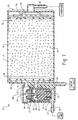
- FIG. 1 is an isometric section view showing a float operated pressure relief valve integrally formed in a common housing with a vapor storage canister with the pressure relief valve in the closed position;
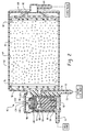
- FIG. 2 is a view similar to FIG. 1 showing an alternative embodiment wherein the relief valve includes a vacuum pressure relief valve for admitting vapor and or air upon sub atmospheric pressure occurring in the fuel tank.
- an exemplary embodiment of the combination pressure relief valve/tipping valve and storage canister is indicated generally at 10 and includes a integrally formed common housing 12 defining a vapor storage chamber 14 with a vapor passage 16 formed in one end thereof and an atmospheric air vent 18 formed in the end distal the passage 16.
- the end into which passage 16 is formed also has a separate purge outlet passage 21 which communicates at right angles with a passage 20 formed therein which communicates externally of the housing 12 through a fitting 23.
- Fitting 23 is adapted for connection, as shown in dashed outline, to the original air inlet.
- Fuel vapor enters chamber 14 through passage 25 in fitting 27 adapted for connection to fuel tank as indicated in dashed line.
- Housing 12 also has formed therein a vapor chamber 22 which maybe integrally formed in the common housing 12 with an open end.
- Chamber 22 is closed by a cap 24 which may be secured and sealed thereon by any suitable expedient such as weldment.
- chamber 14 may be formed with an end open and closed by a cap 26 sealed thereover as for example by weldment; and, the cap 26 may have integrally formed therein the atmospheric vent 18
- the vapor chamber 22 has disposed therein a vapor vent/tipping valve indicated generally at 28 and a vapor pressure relief valve indicated generally at 30 which are disposed at opposite ends of a vapor vent 32 formed in a valve body 34 received in the vapor chamber 22
- the vapor vent/tipping valve includes a float 36 with a flexible valve member 38 disposed on the upper surface thereof for closing against a valve seat 40 formed on the lower end of vapor vent 32.
- the float Upon fuel entering chamber 22 the float is caused to rise; and, upon the float reaching a predetermined level valve member 38 closes against valve seat 40 thereby preventing vapors from escaping the chamber 22.
- the float In addition to its buoyancy in liquid fuel , the float is gravitationally responsive to disorientation such as tipping or rollover for movement to close member 38 against valve seat 40.
- a pressure relief valve indicated generally at 30 includes a valve member 42 disposed within the cover 44 attached to the valve body 34; and, member 42 is normally closed against the upper end of vent 32 under the influence of gravitational forces.
- the weight of valve number 42 is chosen such that the valve remains closed until a predetermined pressure is experienced in the fuel tank and vapor chamber 22 which pressure causes the valve member 42 to move upwardly thereby permitting vapor to escape through passage 16 to the storage canister 14.
- the canister includes baffling surfaces 46 which provide a torturous path for vapor escaping from the canister through purge outlet passage 20 and may include filter material 48 disposed over the baffling surfaces 46.
- the atmospheric vent passage 18 in the distal end of the canister also has baffling surfaces disposed over the interior end of passage 18 and may also include filter material 52 for filtering air entering the storage chamber 14.
- Storage chamber 14 may also include adsorbent material 54.
- Baffle 50 and filter 52 may be biased against the adsorbent material by a suitable spring 56.
- a suitable spring 56 In the present practice, of the embodiment of FIG. 1, it has been found satisfactory to use particularate carbonaceous material such as granular charcoal for the adsorbent 54.
- FIG. 2 another embodiment is illustrated generally at 60 and includes a common housing 62 defining a storage chamber 64 having a vapor passage 66 formed at an end thereof; and, the housing 62 has formed therein an atmospheric vent 69 at an end distal vapor passage 66.
- Housing 62 is formed as a common housing for a fluid of vapor chamber 68 which communicates with vapor passage 66 and has a fluid inlet 70 formed in fitting 71 which is adapted for connection thereto for receiving fuel vapor from a fuel tank as indicated by dashed line in FIG. 2.
- the common housing 62 also has formed therein a purge outlet passage 72 formed in fitting 73 which extends externally from the housing 62 and which is adapted for connection thereto for communicating with the engine air inlet as shown in dashed line Passage 72 also communicates openly through cross passage 74 with storage chamber 64.
- vapor flow from storage chamber 64 may be filtered by suitable filter material 76 and required to pass through a series of baffles 78 before reaching either purge outlet cross passage 74 or vapor passage 66 leading to chamber 68.
- atmospheric air entering through passage 69 in the distal end of the housing 62 may be required to pass through a baffle 80 and a filter material 82 before entering chamber 64.
- storage chamber 64 may also include adsorbent material 84 as, for example particulate carbonaceous material such as granular charcoal. If desired a spring 108 may be employed to bias the baffle 80 and filter 82 against the adsorbent 84.
- Fluid chamber 68 has disposed therein valve body 86 which contains a vapor vent/tipping valve indicated generally at 88 which includes a vertically oriented vent passage 90 with a valve seat 92 formed on the lower end thereof; and, valve 88 may include a float 94 with a flexible valve member 96 disposed on the upper end thereof.
- the valve body includes a cover 98 which retains a gravity operated pressure relief valve member 100 which, under the weight of the member, rests on valve seat 102 formed about the upper end of vent passage 90 for preventing escape of vapor air passage 90 until a predetermined pressure is reached in the fuel tank and fluid pressure chamber 68.
- the gravity operated valve member 100 has a central passage 104 therethrough which has a valve seat formed on the lower end thereof with a movable valve member such as the sphere or ball 106 retained therein.
- a valve member 106 is formed of very light material, as for example, plastic having a relatively low specific gravity.
- valve member 106 serves as a vacuum relief valve upon the occurrence of a slight sub atmospheric pressure in chamber 68, in such event the valve member 106 is caused to drop from the valve seat at the lower end of passage 104 and permits vapor and/or air from storage canister 64 to flow through vapor passage 66 and through the vent passage 90 and passage 70 to the fuel tank.
- This opening of passage 90 thus provides a flow of make up air to prevent collapse of the fuel tank in response to withdrawal of liquid fuel during engine operation or in the event of cooling of the tank below ambient temperature to thereby generate a vacuum in the tank.
- the current embodiments illustrated and described herein above thus present a vapor storage canister and vapor vent/tipping valve and pressure relief valve in a common housing with ports provided thereon for connection via conduits, such as hoses, to the engine fuel tank, engine air inlet and for atmospheric venting.
- conduits such as hoses
Landscapes
- Engineering & Computer Science (AREA)
- Mechanical Engineering (AREA)
- General Engineering & Computer Science (AREA)
- Chemical & Material Sciences (AREA)
- Combustion & Propulsion (AREA)
- Life Sciences & Earth Sciences (AREA)
- Sustainable Development (AREA)
- Sustainable Energy (AREA)
- Transportation (AREA)
- Supplying Secondary Fuel Or The Like To Fuel, Air Or Fuel-Air Mixtures (AREA)
- Cooling, Air Intake And Gas Exhaust, And Fuel Tank Arrangements In Propulsion Units (AREA)
Abstract
Description
- Vapor Vent Valve With Pressure Relief Function Integrated To Carbon Canister.
- In small engines of less than 50 horsepower (37.2 kilowatts) such as those employed for garden tractors, lawn mowers, portable generating sets and marine applications it has recently been mandated that such engines be equipped with fuel vapor emission controls.
- Small engines used for such applications commonly have the fuel tank disposed approximate the engine for facilitating engine installation on the appliance employing the engine. The more widely used configuration utilizes a gravity feed fuel supply from the tank to the engine carburetor; however, in certain applications on engines approaching 50 horsepower, fuel pumps are employed.
- Efforts to provide fuel vapor emission control systems on such small engines and particularly in the aforesaid applications of small engines have required additional components, modifications to the fuel tank and have resulted in significant increases in the cost of installing the engine and fuel system in the appliance. This is particularly the case where it is required to not only prevent fuel vapor emission during periods of engine shutdown but where it is also required to provide a valve which will close the tank make up air vent in the event of disorientation such as tipping or rollover of the appliance in service.
- The more widely employed technique of preventing fuel vapor emission from a large engine tank and fuel system has employed a storage canister charged with adsorbent to retain the fuel vapors until the engine is started and the vapors can then be drawn into the engine air inlet and the canister purged by induction of atmospheric air as the vapors are drawn into the engine. Such systems have long been employed in large engines such as in motor vehicles with fuel tanks remote from the engine.
- However, it has been found difficult and costly to provide these functions for small engines having fuel tanks which are typically bracket mounted on the engine or the appliance in a position adjacent the engine where it is necessary to keep the volume of the engine and tank to a minimum. This has been particularly difficult to achieve for air cool engines where the engine is closely cowled to provide adequate airflow over the cylinder head for proper cooling. In addition, most small engine applications employ gravity feed fuel tanks which are placed above the engine and thus require a particular configuration for the appliance into which the engine is installed, particularly where the engine is cowled. Thus it has been desired to find a way or means of providing the necessary functions for fuel vapor emission control on small engines, particularly those employing gravity feed fuel tanks without requiring complete retooling for the fuel tank and associated fuel system and tank mounting components.
- The present specification drawings and claims describe and illustrate exemplary embodiments which provide a solution to the above described problem and include a fuel vapor storage canister and attached vapor vent/tipping valve and pressure relief valve which are integrally formed in a common housing for convenient mounting adjacent the small engine fuel tank and maybe connected by the appropriate flexible conduits to the fuel tank and engine air inlet. The integral combination described herein provides a compact simple to manufacture and relatively low cost unit which provides for control of fuel vapor emission during periods of engine shutdown and yet provides for purging of stored fuel vapor upon engine start up. In addition, protection against tipping and rollover is also provided. In one illustrated embodiment, the storage canister has attached thereto a float operated vapor vent/tipping valve with "head" or pressure relief valve preventing vapor escape until a predetermined vapor pressure is reached. In another embodiment illustrated, the pressure relief valve includes a vacuum relief valve disposed in the moveable valve member to enable make up air to be drawn into the fuel tank during engine operation or upon tank cooling and condensing of vapor during engine shutdown to prevent collapse of the fuel tank.
- FIG. 1 is an isometric section view showing a float operated pressure relief valve integrally formed in a common housing with a vapor storage canister with the pressure relief valve in the closed position; and
- FIG. 2 is a view similar to FIG. 1 showing an alternative embodiment wherein the relief valve includes a vacuum pressure relief valve for admitting vapor and or air upon sub atmospheric pressure occurring in the fuel tank.
- Referring to FIG. 1, an exemplary embodiment of the combination pressure relief valve/tipping valve and storage canister is indicated generally at 10 and includes a integrally formed
common housing 12 defining avapor storage chamber 14 with avapor passage 16 formed in one end thereof and anatmospheric air vent 18 formed in the end distal thepassage 16. The end into whichpassage 16 is formed also has a separatepurge outlet passage 21 which communicates at right angles with apassage 20 formed therein which communicates externally of thehousing 12 through a fitting 23. Fitting 23 is adapted for connection, as shown in dashed outline, to the original air inlet. Fuel vapor enterschamber 14 throughpassage 25 infitting 27 adapted for connection to fuel tank as indicated in dashed line. -
Housing 12 also has formed therein avapor chamber 22 which maybe integrally formed in thecommon housing 12 with an open end. -
Chamber 22 is closed by acap 24 which may be secured and sealed thereon by any suitable expedient such as weldment. In a similar manner,chamber 14 may be formed with an end open and closed by acap 26 sealed thereover as for example by weldment; and, thecap 26 may have integrally formed therein theatmospheric vent 18 - The
vapor chamber 22 has disposed therein a vapor vent/tipping valve indicated generally at 28 and a vapor pressure relief valve indicated generally at 30 which are disposed at opposite ends of avapor vent 32 formed in avalve body 34 received in thevapor chamber 22 - In the embodiment of FIG. 1, the vapor vent/tipping valve includes a
float 36 with aflexible valve member 38 disposed on the upper surface thereof for closing against avalve seat 40 formed on the lower end ofvapor vent 32. Uponfuel entering chamber 22 the float is caused to rise; and, upon the float reaching a predeterminedlevel valve member 38 closes againstvalve seat 40 thereby preventing vapors from escaping thechamber 22. In addition to its buoyancy in liquid fuel , the float is gravitationally responsive to disorientation such as tipping or rollover for movement to closemember 38 againstvalve seat 40. - A pressure relief valve indicated generally at 30 includes a
valve member 42 disposed within thecover 44 attached to thevalve body 34; and,member 42 is normally closed against the upper end ofvent 32 under the influence of gravitational forces. The weight ofvalve number 42 is chosen such that the valve remains closed until a predetermined pressure is experienced in the fuel tank andvapor chamber 22 which pressure causes thevalve member 42 to move upwardly thereby permitting vapor to escape throughpassage 16 to thestorage canister 14. - The canister includes
baffling surfaces 46 which provide a torturous path for vapor escaping from the canister throughpurge outlet passage 20 and may includefilter material 48 disposed over thebaffling surfaces 46. - In like manner, the
atmospheric vent passage 18 in the distal end of the canister also has baffling surfaces disposed over the interior end ofpassage 18 and may also includefilter material 52 for filtering air entering thestorage chamber 14. -
Storage chamber 14 may also includeadsorbent material 54. Baffle 50 andfilter 52 may be biased against the adsorbent material by asuitable spring 56. In the present practice, of the embodiment of FIG. 1, it has been found satisfactory to use particularate carbonaceous material such as granular charcoal for the adsorbent 54. - Referring to FIG. 2, another embodiment is illustrated generally at 60 and includes a
common housing 62 defining astorage chamber 64 having a vapor passage 66 formed at an end thereof; and, thehousing 62 has formed therein anatmospheric vent 69 at an end distal vapor passage 66.Housing 62 is formed as a common housing for a fluid ofvapor chamber 68 which communicates with vapor passage 66 and has afluid inlet 70 formed in fitting 71 which is adapted for connection thereto for receiving fuel vapor from a fuel tank as indicated by dashed line in FIG. 2. Thecommon housing 62 also has formed therein apurge outlet passage 72 formed infitting 73 which extends externally from thehousing 62 and which is adapted for connection thereto for communicating with the engine air inlet as shown in dashed line Passage 72 also communicates openly throughcross passage 74 withstorage chamber 64. - As illustrated in the embodiment of FIG. 2, vapor flow from
storage chamber 64 may be filtered bysuitable filter material 76 and required to pass through a series ofbaffles 78 before reaching either purgeoutlet cross passage 74 or vapor passage 66 leading tochamber 68. In like manner, atmospheric air entering throughpassage 69 in the distal end of thehousing 62 may be required to pass through abaffle 80 and afilter material 82 before enteringchamber 64. As mentioned both with respect to the embodiment of FIG. 1storage chamber 64 may also includeadsorbent material 84 as, for example particulate carbonaceous material such as granular charcoal. If desired aspring 108 may be employed to bias thebaffle 80 and filter 82 against the adsorbent 84. -
Fluid chamber 68 has disposed thereinvalve body 86 which contains a vapor vent/tipping valve indicated generally at 88 which includes a vertically orientedvent passage 90 with avalve seat 92 formed on the lower end thereof; and,valve 88 may include afloat 94 with a flexible valve member 96 disposed on the upper end thereof. Upon entry of liquid fuel throughinlet 70 intochamber 68 and the interior of thevalve body 86, the float rises; and, upon fuel level reaching a predetermine level, the float movement closes valve member 96 againstvalve seat 92 thus preventing escape of vapor throughvent passage 90. - The valve body includes a
cover 98 which retains a gravity operated pressurerelief valve member 100 which, under the weight of the member, rests onvalve seat 102 formed about the upper end ofvent passage 90 for preventing escape ofvapor air passage 90 until a predetermined pressure is reached in the fuel tank andfluid pressure chamber 68. - In the embodiment of FIG. 2, the gravity operated
valve member 100 has acentral passage 104 therethrough which has a valve seat formed on the lower end thereof with a movable valve member such as the sphere orball 106 retained therein. Avalve member 106 is formed of very light material, as for example, plastic having a relatively low specific gravity. - The slightest positive vapor pressure in the
vent passage 90 causesball 106 to move upward from the position shown in FIG. 2 in solid line to the position shown in dashed outline or against the valve seat formed on the lower end ofpassage 104. Valvemember 106 serves as a vacuum relief valve upon the occurrence of a slight sub atmospheric pressure inchamber 68, in such event thevalve member 106 is caused to drop from the valve seat at the lower end ofpassage 104 and permits vapor and/or air fromstorage canister 64 to flow through vapor passage 66 and through thevent passage 90 andpassage 70 to the fuel tank. This opening ofpassage 90 thus provides a flow of make up air to prevent collapse of the fuel tank in response to withdrawal of liquid fuel during engine operation or in the event of cooling of the tank below ambient temperature to thereby generate a vacuum in the tank. - The current embodiments illustrated and described herein above thus present a vapor storage canister and vapor vent/tipping valve and pressure relief valve in a common housing with ports provided thereon for connection via conduits, such as hoses, to the engine fuel tank, engine air inlet and for atmospheric venting. These embodiments thus present a compact, simple and relatively low cost fuel vapor emission control system which may readily be added to existing small engines and their fuel tanks without costly modifications.
- Although exemplary embodiments have been described and illustrated hereinabove, it will be understood that modifications and variations may be made by those skilled in the art within the scope of the following claims.
Claims (17)
- An integral vapor vent/tipping valve and vapor storage assembly (10, 60) for use with a small engine fuel tank comprising:(a) a housing (12, 62) integrally formed to define a fluid receiving chamber (22, 68) with an inlet port (25, 70) adapted for receiving fuel vapor from the fuel tank, said housing also defining integrally therewith a vapor storage chamber (14, 64) with a purge outlet (21, 72) and an atmospheric vent (18, 69), said storage chamber communicating with the fluid receiving chamber through a vapor passage (16, 66);(b) a pressure relief valve (30, 88) associated said fluid receiving chamber and operable to permit vapor flow through said vapor passage to said storage chamber when a predetermined pressure is reached in said fluid receiving chamber; and,(c) a tipping valve (28, 88) associated with said fluid receiving chamber and operable to prevent communication through said vapor passage upon disorientation of said housing.
- The assembly defined in claim 1, wherein said tipping valve includes a float (36, 94) operable to close said tipping valve when fuel in the tank rises to a predetermined level.
- The assembly defined in claim 1, wherein said pressure relief valve includes a vacuum relief valve (42, 106) operable to permit reverse flow upon occurrence of sub-atmospheric pressure in said fluid receiving chamber.
- The assembly defined in claim 3, wherein said vacuum relief valve includes a spherical valve member (106).
- The assembly defined in claim 3, wherein said pressure relief valve includes a gravity responsive member (100) biased to the closed position under gravitational forces.
- The assembly defined in claim 1, wherein said vapor storage chamber is charged with adsorbent material (54, 84).
- The assembly defined in claim 6, wherein said adsorbent material comprises carbonaceous particulate material.
- The assembly defined in claim 1, wherein said vapor passage includes baffling (46, 78).
- The assembly defined in claim 1, wherein said storage chamber and said fluid receiving chamber are molded as a one piece member.
- The assembly defined in claim 8, wherein said storage chamber and said fluid receiving chamber are molded in said one piece member as open cavities and closed by a cap (24, 26) secured by weldment.
- The assembly defined in claim 1, wherein said storage chamber includes material (54, 84) for filtering flow through said purge outlet and said atmospheric vent.
- The assembly defined in claim 1, wherein said purge outlet includes baffling (78).
- The assembly defined in claim 1, wherein said atmospheric vent includes baffling (50,80)
- The assembly defined in claim 1, wherein said storage chamber includes material filtering (54, 84) flow through said vapor passage.
- A method of making an integral vapor vent/tipping valve and vapor storage device (10, 60) for a small engine fuel tank comprising:(a) forming integrally a housing (12, 62) with a fluid receiving chamber (22, 68) with a fluid receiving port (25, 62) and a vapor storage chamber with a purge outlet (21, 72) and an atmospheric vent (18, 69) and communicating said storage chamber with said fluid receiving chamber through a vapor passage (16, 66);(b) disposing a pressure relief valve (30, 88) in said fluid receiving chamber and preventing flow through said vapor passage until a predetermined pressure is reached in said fluid receiving chamber; and,(c) disposing a vapor vent/tipping valve (28, 88) in said fluid receiving chamber and preventing fluid escape therefrom upon disorientation of said housing.
- The method defined in claim 15, wherein the step of disposing a vapor vent/tipping valve includes disposing a float (36, 94) operative to close the valve when fuel rises to a predetermined level in the tank.
- The method defined in claim 15, wherein the step of integrally forming a housing includes forming the fluid receiving chamber and the storage chamber together in a common member.
Applications Claiming Priority (1)
| Application Number | Priority Date | Filing Date | Title |
|---|---|---|---|
| US11/081,418 US7249595B2 (en) | 2005-03-16 | 2005-03-16 | Vapor vent valve with pressure relief function integrated to carbon canister |
Publications (1)
| Publication Number | Publication Date |
|---|---|
| EP1702785A1 true EP1702785A1 (en) | 2006-09-20 |
Family
ID=36589193
Family Applications (1)
| Application Number | Title | Priority Date | Filing Date |
|---|---|---|---|
| EP06004809A Withdrawn EP1702785A1 (en) | 2005-03-16 | 2006-03-09 | Vapor vent valve with pressure relief function integrated to carbon canister |
Country Status (6)
| Country | Link |
|---|---|
| US (1) | US7249595B2 (en) |
| EP (1) | EP1702785A1 (en) |
| JP (1) | JP5041118B2 (en) |
| KR (1) | KR101278853B1 (en) |
| CN (1) | CN1834515A (en) |
| CA (1) | CA2539516A1 (en) |
Cited By (3)
| Publication number | Priority date | Publication date | Assignee | Title |
|---|---|---|---|---|
| FR2954805A1 (en) * | 2009-12-24 | 2011-07-01 | Inergy Automotive Systems Res | VALVE FOR AIR FLOW CIRCUIT OF A LIQUID TANK |
| WO2016049310A1 (en) * | 2014-09-24 | 2016-03-31 | Eaton Corporation | Active drain liquid trap for fuel system |
| WO2019025696A1 (en) * | 2017-08-02 | 2019-02-07 | Sogefi Filtration | Pressure regulating device and method for assembling same, for a fuel vapour absorber |
Families Citing this family (21)
| Publication number | Priority date | Publication date | Assignee | Title |
|---|---|---|---|---|
| US20070128878A1 (en) * | 2003-03-03 | 2007-06-07 | Manabu Izumi | Substrate processing apparatus and method for producing a semiconductor device |
| US7225798B2 (en) * | 2005-05-31 | 2007-06-05 | Sentec E&E Co., Ltd. | Device combing fuel control valve and carbon canister, or fuel tank |
| US7225799B2 (en) * | 2005-07-12 | 2007-06-05 | Sentec E&E Co., Ltd. | Device combining two-way valve and carbon canister and fuel tank with the same |
| US7476269B2 (en) * | 2005-12-02 | 2009-01-13 | Delphi Technologies, Inc. | Evaporative emissions canister suitable for marine use |
| US7677277B2 (en) * | 2005-12-29 | 2010-03-16 | Eaton Corporation | Fuel tank cap with integrated carbon canister |
| KR100851017B1 (en) | 2006-05-08 | 2008-08-12 | 피엔케이산업(주) | Canister Close Valve Unit |
| US20120003915A1 (en) * | 2008-08-14 | 2012-01-05 | Arun Kumar Sinha | Air Breather Valve Assembly |
| WO2010146452A1 (en) * | 2009-06-17 | 2010-12-23 | Eaton Corporation | Vapor vent valve with pressure relief function integrated to carbon canister |
| US8833346B2 (en) * | 2009-10-09 | 2014-09-16 | Brunswick Corporation | Apparatus and methods for mounting fuel delivery system components to fuel tanks |
| US20110168715A1 (en) * | 2010-01-13 | 2011-07-14 | Eaton Corporation | Fuel cap with emissions protection |
| CN101881241A (en) * | 2010-07-16 | 2010-11-10 | 浙江吉利汽车研究院有限公司 | Three-way valve for car carbon canister |
| DE102011116941A1 (en) * | 2011-10-26 | 2013-05-02 | Kautex Textron Gmbh & Co. Kg | vent valve |
| CN102536527A (en) * | 2011-12-06 | 2012-07-04 | 中国嘉陵工业股份有限公司(集团) | Fuel evaporation control system |
| KR101755895B1 (en) * | 2015-11-24 | 2017-07-07 | 현대자동차주식회사 | Fuel auxiliary tank for flexible fuel vehicle |
| JP7340038B2 (en) * | 2019-12-24 | 2023-09-06 | 株式会社パイオラックス | valve device |
| US11796102B2 (en) | 2021-01-26 | 2023-10-24 | Cooper-Standard Automotive Inc. | Quick connector with modular flow control insert |
| US12158124B2 (en) | 2021-07-09 | 2024-12-03 | Stant Usa Corp. | Carbon canister with integrated fuel tank isolation valve |
| WO2023069416A1 (en) | 2021-10-18 | 2023-04-27 | Stant Usa Corp. | Carbon canister with direct connect fuel tank isolation valve |
| EP4419365A4 (en) * | 2021-10-18 | 2025-12-03 | Stant Usa Corp | CARBON CANISTER WITH DIRECTLY ATTACHED FUEL TANK SHUT-OFF VALVE |
| US12264640B1 (en) * | 2023-05-18 | 2025-04-01 | Shop 48 LLC | Vapor canister |
| CN116624640B (en) * | 2023-06-27 | 2026-04-21 | 上海大创汽车技术有限公司 | Safety valve and gas-liquid separator |
Citations (8)
| Publication number | Priority date | Publication date | Assignee | Title |
|---|---|---|---|---|
| US5004002A (en) * | 1989-04-17 | 1991-04-02 | Nissan Motor Co., Ltd. | Fuel check valve assembly for fuel tank |
| US5183087A (en) * | 1991-06-10 | 1993-02-02 | Borg-Warner Automotive Electronic & Mechanical Systems Corporation | Refueling vapor recovery system |
| FR2686840A1 (en) * | 1992-02-04 | 1993-08-06 | Peugeot | Venting device for a fuel tank |
| US5450833A (en) * | 1991-12-06 | 1995-09-19 | Robert Bosch Gmbh | Breather for an internal combustion engine fuel tank |
| US5666989A (en) * | 1994-11-08 | 1997-09-16 | Stant Manufacturing Inc. | Tank venting control assembly |
| US5749347A (en) * | 1996-07-30 | 1998-05-12 | Denso Corporation | Fuel leakage prevention system having latch-engaged valve |
| US5983958A (en) * | 1994-08-24 | 1999-11-16 | G.T. Products, Inc. | Onboard vapor recovery system with two stage shutoff valve |
| US6343590B1 (en) * | 1999-07-08 | 2002-02-05 | Aisan Kogyo Kabushiki Kaisha | Canister module |
Family Cites Families (14)
| Publication number | Priority date | Publication date | Assignee | Title |
|---|---|---|---|---|
| US4655238A (en) * | 1986-03-07 | 1987-04-07 | Stant Inc. | Roll-over valve |
| DE3803670C1 (en) * | 1988-02-06 | 1988-07-28 | Daimler-Benz Ag, 7000 Stuttgart, De | |
| JPH02157467A (en) * | 1988-12-09 | 1990-06-18 | Hitachi Ltd | Canister |
| JPH0734985A (en) * | 1993-07-23 | 1995-02-03 | Kubota Corp | Evaporative fuel adsorption device for small general-purpose engine |
| JP3313252B2 (en) * | 1994-10-04 | 2002-08-12 | 京三電機株式会社 | Evaporation control valve |
| US5687778A (en) * | 1995-05-01 | 1997-11-18 | Stant Manufacturing Inc. | Dual valve tank venting system |
| DE19523936A1 (en) * | 1995-06-30 | 1997-01-02 | Bosch Gmbh Robert | Pumping device for a fuel evaporation retention system and fuel evaporation retention system |
| DE19644610A1 (en) * | 1996-10-26 | 1998-04-30 | Bosch Gmbh Robert | Tank ventilation device for motor vehicles |
| SE512575C2 (en) * | 1998-08-21 | 2000-04-03 | Volvo Ab | Ventilation system for fuel tanks |
| JP3638842B2 (en) * | 1999-12-15 | 2005-04-13 | 愛三工業株式会社 | Fuel supply device |
| US6450833B1 (en) * | 2000-08-25 | 2002-09-17 | Wabash Technology Corporation | Seven-way trailer connector |
| US6691725B2 (en) * | 2001-12-14 | 2004-02-17 | Eaton Corporation | Fuel vapor vent valve with peel-off mechanism for ensuring reopening |
| US7047951B2 (en) * | 2003-10-03 | 2006-05-23 | Tecumseh Products Company | Centrifugally operated evaporative emissions control valve system for internal combustion engines |
| US7568494B2 (en) * | 2005-03-29 | 2009-08-04 | Stant Manufacturing Inc. | Electronic fuel tank fill limit control |
-
2005
- 2005-03-16 US US11/081,418 patent/US7249595B2/en not_active Expired - Lifetime
-
2006
- 2006-03-09 EP EP06004809A patent/EP1702785A1/en not_active Withdrawn
- 2006-03-14 CA CA002539516A patent/CA2539516A1/en not_active Abandoned
- 2006-03-15 JP JP2006071063A patent/JP5041118B2/en not_active Expired - Fee Related
- 2006-03-15 CN CNA2006100574694A patent/CN1834515A/en active Pending
- 2006-03-15 KR KR1020060023967A patent/KR101278853B1/en not_active Expired - Fee Related
Patent Citations (8)
| Publication number | Priority date | Publication date | Assignee | Title |
|---|---|---|---|---|
| US5004002A (en) * | 1989-04-17 | 1991-04-02 | Nissan Motor Co., Ltd. | Fuel check valve assembly for fuel tank |
| US5183087A (en) * | 1991-06-10 | 1993-02-02 | Borg-Warner Automotive Electronic & Mechanical Systems Corporation | Refueling vapor recovery system |
| US5450833A (en) * | 1991-12-06 | 1995-09-19 | Robert Bosch Gmbh | Breather for an internal combustion engine fuel tank |
| FR2686840A1 (en) * | 1992-02-04 | 1993-08-06 | Peugeot | Venting device for a fuel tank |
| US5983958A (en) * | 1994-08-24 | 1999-11-16 | G.T. Products, Inc. | Onboard vapor recovery system with two stage shutoff valve |
| US5666989A (en) * | 1994-11-08 | 1997-09-16 | Stant Manufacturing Inc. | Tank venting control assembly |
| US5749347A (en) * | 1996-07-30 | 1998-05-12 | Denso Corporation | Fuel leakage prevention system having latch-engaged valve |
| US6343590B1 (en) * | 1999-07-08 | 2002-02-05 | Aisan Kogyo Kabushiki Kaisha | Canister module |
Cited By (7)
| Publication number | Priority date | Publication date | Assignee | Title |
|---|---|---|---|---|
| FR2954805A1 (en) * | 2009-12-24 | 2011-07-01 | Inergy Automotive Systems Res | VALVE FOR AIR FLOW CIRCUIT OF A LIQUID TANK |
| US8763626B2 (en) | 2009-12-24 | 2014-07-01 | Inergy Automotive Systems Research (Societe Anonyme) | Valve for the venting circuit of a liquid tank |
| WO2016049310A1 (en) * | 2014-09-24 | 2016-03-31 | Eaton Corporation | Active drain liquid trap for fuel system |
| US10378673B2 (en) | 2014-09-24 | 2019-08-13 | Eaton Corporation | Active drain liquid trap for fuel system |
| WO2019025696A1 (en) * | 2017-08-02 | 2019-02-07 | Sogefi Filtration | Pressure regulating device and method for assembling same, for a fuel vapour absorber |
| FR3069811A1 (en) * | 2017-08-02 | 2019-02-08 | Sogefi Filtration | PRESSURE REGULATING DEVICE AND METHOD OF ASSEMBLING FOR A FUEL VAPOR ABSORBER |
| US11105301B2 (en) | 2017-08-02 | 2021-08-31 | Sogefi Filtration | Pressure regulating device and method for assembling same, for a fuel vapour absorber |
Also Published As
| Publication number | Publication date |
|---|---|
| JP2006258101A (en) | 2006-09-28 |
| US7249595B2 (en) | 2007-07-31 |
| JP5041118B2 (en) | 2012-10-03 |
| KR101278853B1 (en) | 2013-07-01 |
| KR20060100268A (en) | 2006-09-20 |
| US20060207576A1 (en) | 2006-09-21 |
| CA2539516A1 (en) | 2006-12-16 |
| CN1834515A (en) | 2006-09-20 |
Similar Documents
| Publication | Publication Date | Title |
|---|---|---|
| US7249595B2 (en) | Vapor vent valve with pressure relief function integrated to carbon canister | |
| US7201155B2 (en) | Integral vapor storage and vent valve assembly for use with a small engine fuel tank and vapor emission system employing same | |
| US5960817A (en) | Control valve and system for fuel vapor recovery | |
| US6213100B1 (en) | Multi-function fuel pump module | |
| JP3909231B2 (en) | Vent valve and fuel pump module | |
| US5669361A (en) | Vehicle refueling valve | |
| US5718208A (en) | Fuel vapor management system | |
| US7383825B2 (en) | Small engine fuel tank with integrated evaporative controls | |
| CN105857059B (en) | Valve assembly for high pressure fluid container | |
| EP1705051B1 (en) | Low profile overfill limit device with reverse flow capability | |
| US7503314B2 (en) | Marine fuel vapor separator with vent control device | |
| US20020017281A1 (en) | Vent and rollover valve and fuel pump module | |
| US6874484B2 (en) | Fuel vapor vent system and low permeation vacuum operated shut-off valve therefor | |
| US20100218748A1 (en) | Device for the Venting Circuit of a Liquid Tank and Valve Incorporating Said Device | |
| US7234452B2 (en) | Controlling vapor emission in a small engine fuel tank system | |
| US6848463B2 (en) | Vapor vent valve | |
| EP1600317B1 (en) | Refueling vapor recovery system | |
| US7438059B2 (en) | Evaporative emission control system and method for small engines | |
| US7213583B2 (en) | Small engine fuel tank with integrated evaporative controls | |
| US5947153A (en) | Fuel tank filler neck with bypass passage | |
| WO2010146452A1 (en) | Vapor vent valve with pressure relief function integrated to carbon canister | |
| US20060260696A1 (en) | Fuel delivery and vapor control system | |
| JPS63192613A (en) | Exhaustion preventive device for vaporized fuel |
Legal Events
| Date | Code | Title | Description |
|---|---|---|---|
| PUAI | Public reference made under article 153(3) epc to a published international application that has entered the european phase |
Free format text: ORIGINAL CODE: 0009012 |
|
| AK | Designated contracting states |
Kind code of ref document: A1 Designated state(s): AT BE BG CH CY CZ DE DK EE ES FI FR GB GR HU IE IS IT LI LT LU LV MC NL PL PT RO SE SI SK TR |
|
| AX | Request for extension of the european patent |
Extension state: AL BA HR MK YU |
|
| 17P | Request for examination filed |
Effective date: 20061216 |
|
| 17Q | First examination report despatched |
Effective date: 20070117 |
|
| AKX | Designation fees paid |
Designated state(s): DE FR GB IT |
|
| STAA | Information on the status of an ep patent application or granted ep patent |
Free format text: STATUS: EXAMINATION IS IN PROGRESS |
|
| STAA | Information on the status of an ep patent application or granted ep patent |
Free format text: STATUS: THE APPLICATION IS DEEMED TO BE WITHDRAWN |
|
| 18D | Application deemed to be withdrawn |
Effective date: 20191001 |