EP1702694A1 - Tool chuck for rotating machine, provided with locking means - Google Patents
Tool chuck for rotating machine, provided with locking means Download PDFInfo
- Publication number
- EP1702694A1 EP1702694A1 EP06356023A EP06356023A EP1702694A1 EP 1702694 A1 EP1702694 A1 EP 1702694A1 EP 06356023 A EP06356023 A EP 06356023A EP 06356023 A EP06356023 A EP 06356023A EP 1702694 A1 EP1702694 A1 EP 1702694A1
- Authority
- EP
- European Patent Office
- Prior art keywords
- locking
- central piece
- clamping ring
- jaws
- finger
- Prior art date
- Legal status (The legal status is an assumption and is not a legal conclusion. Google has not performed a legal analysis and makes no representation as to the accuracy of the status listed.)
- Granted
Links
Images


Classifications
-
- B—PERFORMING OPERATIONS; TRANSPORTING
- B23—MACHINE TOOLS; METAL-WORKING NOT OTHERWISE PROVIDED FOR
- B23B—TURNING; BORING
- B23B31/00—Chucks; Expansion mandrels; Adaptations thereof for remote control
- B23B31/02—Chucks
- B23B31/10—Chucks characterised by the retaining or gripping devices or their immediate operating means
- B23B31/12—Chucks with simultaneously-acting jaws, whether or not also individually adjustable
- B23B31/1207—Chucks with simultaneously-acting jaws, whether or not also individually adjustable moving obliquely to the axis of the chuck in a plane containing this axis
- B23B31/123—Chucks with simultaneously-acting jaws, whether or not also individually adjustable moving obliquely to the axis of the chuck in a plane containing this axis with locking arrangements
-
- B—PERFORMING OPERATIONS; TRANSPORTING
- B23—MACHINE TOOLS; METAL-WORKING NOT OTHERWISE PROVIDED FOR
- B23B—TURNING; BORING
- B23B2231/00—Details of chucks, toolholder shanks or tool shanks
- B23B2231/38—Keyless chucks for hand tools
-
- Y—GENERAL TAGGING OF NEW TECHNOLOGICAL DEVELOPMENTS; GENERAL TAGGING OF CROSS-SECTIONAL TECHNOLOGIES SPANNING OVER SEVERAL SECTIONS OF THE IPC; TECHNICAL SUBJECTS COVERED BY FORMER USPC CROSS-REFERENCE ART COLLECTIONS [XRACs] AND DIGESTS
- Y10—TECHNICAL SUBJECTS COVERED BY FORMER USPC
- Y10T—TECHNICAL SUBJECTS COVERED BY FORMER US CLASSIFICATION
- Y10T279/00—Chucks or sockets
- Y10T279/17—Socket type
- Y10T279/17615—Obliquely guided reciprocating jaws
- Y10T279/17641—Threaded central cone and jaw
-
- Y—GENERAL TAGGING OF NEW TECHNOLOGICAL DEVELOPMENTS; GENERAL TAGGING OF CROSS-SECTIONAL TECHNOLOGIES SPANNING OVER SEVERAL SECTIONS OF THE IPC; TECHNICAL SUBJECTS COVERED BY FORMER USPC CROSS-REFERENCE ART COLLECTIONS [XRACs] AND DIGESTS
- Y10—TECHNICAL SUBJECTS COVERED BY FORMER USPC
- Y10T—TECHNICAL SUBJECTS COVERED BY FORMER US CLASSIFICATION
- Y10T279/00—Chucks or sockets
- Y10T279/32—Means to prevent jaw loosening
Definitions
- the present invention relates to a tool chuck for the equipment of a rotating machine, provided with locking means.
- a chuck mounted on the shaft of a rotating machine is intended to achieve the attachment of a tool, such as a drill if it is a drilling tool.
- Fixing the tool on the mandrel is commonly done by means of three jaws converging forward, driven and guided by different means in the mandrel, so that the axial displacement of the jaws forward is translated by bringing them together to achieve the clamping of the tool, while the rearward movement of the jaws is accompanied by a loosening of the tool.
- a mandrel of the aforementioned type is generally equipped with a central piece which has on the one hand a rear part intended to be fixed to the rotating machine and on the other hand a front part with which the jaws are associated, and which is surrounded a clamping ring.
- the jaws By rotating the clamping ring, a user can actuate the mandrel.
- the jaws have an externally threaded portion which can be rotated by a peripheral nut which is driven by the clamping ring.
- the rotation of the clamping ring relative to the central piece leads to the clamping or loosening of the jaws in the direction of rotation.
- Mandrels are also known in which the central piece has a threaded front portion.
- These mandrels comprise a body surrounding the central part, in which there are formed housing converging forwards, and jaws mounted and guided in translation in these housing.
- the jaws comprise a toothing on their inner face, cooperating with the threading of the central piece for their displacement between the clamping position and the loosened position and for the rotating the tool.
- the clamping ring is mounted around the body so as to pivot relative thereto.
- Self-tightening type mandrels have many advantages in terms of ease of use and clamping power. Nevertheless, a major problem penalizes them, namely the impossibility of using them in rotation on the left (the central part of the self-tightening mandrel presenting a thread on the right), because they open then almost instantly because of their own structure .
- the object of the invention is therefore to provide a mandrel provided with a simple and robust locking system, actuated automatically at the end of closure of the jaws, which makes it possible to counter the opening torque of a mandrel, and in particular of a self-tightening type mandrel working in rotation on the left.
- the actuating portion of the locking finger comprises a locking housing and an unlocking housing spaced apart radially from each other and each having an opening facing the clamping ring, and the clamping ring.
- the clamping ring comprises a locking lug and an unlocking lug protruding inwards and radially spaced apart from each other by a distance greater than the radial spacing between the locking and unlocking housing of the finger, the locking ring clamping being adapted to be rotated relative to the rotating part between the locking position, in which the locking pin cooperates with the locking housing and the unlocking position, in which the unlocking lug cooperates with the housing; unlocking.
- the locking portion of the locking finger may have, in the vicinity of the opening of the rotating part, and relative to the first direction of rotation of the central part, a curved upstream face and a convex downstream face, the pivoting of the finger locking in a plane transverse to the mandrel around a wall of the opening being made around a fictitious axis located in the recess formed by the upstream curved face. As a result, pivoting of the locking finger relative to the rotating part is facilitated.
- the locking finger once actuated in its locking position, is bent between the teeth of the central part and the rotating part, when a release action is exerted, so that 'is the finger that cash all efforts, excluding the actuating elements. There is therefore no risk of accidental loosening, as in the case of a locking device employing elastic elements.
- the mandrel 1 firstly comprises a central piece 2, of axis 3, comprising a rear portion 4 intended to be fixed on a motor shaft of the rotating machine, a central portion 5 having a peripheral toothing 6 oriented axially, and a front part 7 having a frustoconical shape converging towards the front, provided with an external thread 8 on the right.
- the mandrel 1 also comprises a body 9 surrounding the central piece 2 and rotatably mounted relative to the central piece 2.
- the body has a substantially cylindrical casing 10 of axis 11, from which radially project three housing 12 converging towards the front and substantially uniformly distributed on the periphery.
- an opening 13 is formed in the casing 10 of the body 9, approximately one third of the radial distance between two adjacent housings 12.
- the opening 13 is located facing the peripheral toothing 6 of the central piece 2, when the body 9 is mounted on the central piece 2, and is delimited by a front wall 14 and a rear wall orthogonal to the axis 11 of the casing 10 and two side walls 15 perpendicular to the front walls 14 and rear.
- the body 9 is here formed from a sheet comprising three wings folded on themselves, shown with different hatching in the sectional views ( Figures 6 and 7).
- the mandrel 1 further comprises jaws 16, each being mounted and guided in translation in a housing 12 of the body 9.
- Each jaw 16 has a toothing 17 on its inner face, intended to cooperate with the thread 8 of the central piece 2.
- a clamping ring 18, with axis 19, is mounted around the body 9, in front of the mandrel 1, substantially coaxially.
- the clamping ring 18 comprises a rearwardly open dome-shaped envelope 20 whose inside diameter is slightly greater than the outside diameter of the housings 12 all along the axis, so that the body 9 fits perfectly into the housing. the clamping ring 18.
- the clamping ring 18 comprises three members 21, 22, 23 having in section a crown portion portion coaxial with the casing 20.
- the members 21, 22, 23 are substantially uniformly distributed at the inner periphery of the casing 20 and protrude axially rearwardly beyond the rear edge 24 of the casing 20.
- the members 21, 22, 23 have a radial thickness less than the radial distance between the inner face of the casing 20 of the clamping ring 18 and the outer face of the casing 10 of the body 9, in the assembled state, and a circumferential length less than the circumferential spacing between two housings 12 of the body 9.
- each member 21, 22, 23 extends over a circular arc of approximately 60 to 80 °.
- the clamping ring 18 can pivot around the body 9 at a limited angular amplitude, each member 21, 22, 23 moving in rotation between two extreme positions defined by the abutment against a housing 12.
- the amplitude of this displacement is for example of the order of 20 to 40 °.
- One of the three members 21 comprises two annular grooves 25, each made from a circumferential end of the member 21, substantially on the same circular arc and at the rear edge 24 of the envelope 20, for a distance less than half of the circumferential length of the member 21.
- the rear part of the member 21 forms a lug 26 in the form of a crown portion, connected to the casing 20 by a bridge of material 27.
- the tab 26 has a recess made from its inner face, substantially circumferentially centered, so that the lug 26 has at its end circumferential two lugs, respectively a locking lug 28 and an unlocking lug 29.
- the locking lug 28 has a circumferential length greater than the unlocking pin 29.
- the lug 26 can be elastically deformed in a transverse plane (orthogonal to the axis of the mandrel) so as to bring the lugs closer to or away from each other. 28, 29 of each other. Furthermore, the contour of the lugs 28, 29 is rounded to facilitate their movement and sliding along different surfaces, as will be seen later.
- a metal nose 30 is further mounted inside the clamping ring 18.
- the nose 30 projects in part from the front of the mandrel 1 and is provided with a central opening allowing the jaws 16 and the jaw to pass through. 'tool.
- the mandrel 1 also comprises a rear ring 31 engaged around the rear portion 4 the central piece 2 substantially coaxially.
- the rear ring 31 and the clamping ring 18 are substantially adjacent and of the same diameter in their zone of adjacency, the mandrel 1 thus having a substantially continuous lateral envelope.
- the rear ring 31 comprises a cylindrical portion 32 engaged on the rear portion 4 of the central piece 2, extended towards the outside by a radial portion 33 in the shape of a ring, itself extended outwards by a skirt 34 substantially cylindrical.
- the rear portion 4 of the central piece 2 and the cylindrical portion 32 of the rear ring comprise reciprocal means for locking in rotation and in axial translation.
- the mandrel 1 comprises a locking pin 35 intended to be engaged in the opening 13 of the body 9.
- the locking pin 35 is formed from a metal plate by cutting or embossing, and comprises a front face and a rear face 36 substantially flat and parallel, spaced from each other by a distance substantially equal to the distance between the front walls 14 and rear of the opening 13.
- the locking pin 35 comprises an elongate actuating portion 37 whose inner face 38 is substantially flat and whose outer face 39, generally parallel to the inner face 38, comprises two disk-shaped indentations, forming one a locking housing 40 and the other an unlocking housing 41.
- the housings 40, 41 are spaced from each other in a direction parallel to the front and rear faces of the finger 35 by a distance less than the circumferential distance between the unlocking pin 29 and the locking pin 28.
- upstream and "downstream”, each of which designates one side of the locking pin 35, when viewed from its rear face 36, respectively the side of the unlocking housing 41 and the side locking housing 40.
- the upstream face 42 and the downstream face 43 of the actuating portion 37 of the locking pin 35 are curved and define sliding ramps of the locking lugs 28 and unlocking 29 as will be seen later.
- the locking pin 35 further comprises a locking portion 44 projecting substantially perpendicularly from the inner face 38 of the actuating portion 37, non-centrally but offset downstream.
- the blocking portion 44 comprises a convex downstream face 45 forming a sliding pad, located substantially at the right of the locking housing 40.
- the upstream face 46 comprises a first curved portion forming a recess 47 in which is located the imaginary axis 48 of the connecting fillet 49 in the cylinder portion between the upstream face 46 of the locking portion 44 and the inner face 38 of the actuating portion 37.
- the upstream face 46 then has a curved portion formed by a shoe 50 projecting towards the upstream substantially parallel to the actuating portion 37 and at least partly facing thereof.
- the part of blocking 44 thus has substantially the shape of a crooked hook upstream.
- the free end portion of the locking portion 44 is in the form of a tooth 51 comprising an exhaust face 52 upstream and a blocking face 53 downstream.
- the locking portion 44 of the locking finger 35 is engaged in the opening 13 of the body 9, the inner face 38 of the actuating portion 37 coming into contact with the outer face of the casing 10 of the body 9. Then the clamping ring 18 is engaged around the body 9 and the locking pin 35, so that the tab 26 is located between the same two housings 12 as the locking pin 35.
- mandrel 1 The operation of mandrel 1 is as follows.
- the clamping ring 18 is rotated relative to the central piece 2 in the counterclockwise direction (according to the view of FIG. 6 ).
- the unlocking pin 29 remains placed in the unlocking housing 41 and thereby causes the body 9 to rotate around the central part 2, via the locking finger 35. Since the locking pin 35 is still not in position. contact with the peripheral toothing 6, it does not oppose the relative rotation of the clamping ring assembly 18 - body 9 with respect to the central piece 2.
- the jaws 16, because of the cooperation between their toothing 17 and the thread 8 of the central part 2 are moved in the housing 12 of the body 9 towards the front of the mandrel 1 and brought closer to each other.
- the locking pin 35 can therefore rotate in the opposite direction of the clockwise, this movement being limited by the locking pin 28 connected to the tab 26 elastically deformable. It follows that the locking pin 35 is driven by a reciprocating pivoting movement in a transverse plane, in the manner of a ratchet of a ratchet wheel system, and generates a characteristic pinging sound.
- the locking pin 28 leaves the locking housing 40, then the unlocking pin takes position in the unlocking housing 41, causing the pivoting of the locking pin 35 around the imaginary axis 48 , the tooth 51 thus leaving the contact of the peripheral toothing 6 of the central piece 2.
- the clamping ring 18 can then freely drive the body 9 in rotation in the direction of clockwise, the jaws 16 being moved towards the position where they are retracted inside the mandrel 1 and spaced from each other, the tool can then be removed from the mandrel 1.
Abstract
Description
La présente invention concerne un mandrin porte-outil pour l'équipement d'une machine tournante, muni de moyens de verrouillage.The present invention relates to a tool chuck for the equipment of a rotating machine, provided with locking means.
Un mandrin monté sur l'arbre d'une machine tournante vise à réaliser la fixation d'un outil, tel qu'un foret s'il s'agit d'un outil de perçage. La fixation de l'outil sur le mandrin est couramment réalisée par l'intermédiaire de trois mors convergeant vers l'avant, entraînés et guidés par différents moyens ménagés dans le mandrin, de telle sorte que le déplacement axial des mors vers l'avant se traduit par un rapprochement de ceux-ci en vue de réaliser le serrage de l'outil, tandis que le déplacement vers l'arrière des mors s'accompagne d'un desserrage de l'outil.A chuck mounted on the shaft of a rotating machine is intended to achieve the attachment of a tool, such as a drill if it is a drilling tool. Fixing the tool on the mandrel is commonly done by means of three jaws converging forward, driven and guided by different means in the mandrel, so that the axial displacement of the jaws forward is translated by bringing them together to achieve the clamping of the tool, while the rearward movement of the jaws is accompanied by a loosening of the tool.
Un mandrin du type précité est en général équipé d'une pièce centrale qui présente d'une part une partie arrière destinée à être fixée à la machine tournante et d'autre part une partie avant à laquelle sont associés les mors, et qui est entourée d'une bague de serrage.A mandrel of the aforementioned type is generally equipped with a central piece which has on the one hand a rear part intended to be fixed to the rotating machine and on the other hand a front part with which the jaws are associated, and which is surrounded a clamping ring.
Par mise en rotation de la bague de serrage, un utilisateur peut actionner le mandrin. A cet effet, les mors possèdent une partie filetée extérieurement pouvant être entraînée en rotation par un écrou périphérique qui est entraîné par la bague de serrage. La rotation de la bague de serrage par rapport à la pièce centrale conduit au serrage ou au desserrage des mors selon le sens de rotation.By rotating the clamping ring, a user can actuate the mandrel. For this purpose, the jaws have an externally threaded portion which can be rotated by a peripheral nut which is driven by the clamping ring. The rotation of the clamping ring relative to the central piece leads to the clamping or loosening of the jaws in the direction of rotation.
Or, lors de l'utilisation de la machine tournante, les vibrations et/ou les efforts exercés sur l'outil peuvent conduire au desserrage de celui-ci. Il existe des systèmes de verrouillage qui permettent d'éviter un desserrage de l'outil. Mais de tels systèmes, s'ils permettent d'éviter le desserrage des mors sous l'effet des vibrations générées lors du travail en percussion, ne permettent en aucun cas de contrer un couple important de desserrage. De plus, les systèmes connus sont constitués de nombreuses petites pièces dont le positionnement relatif et la fixation sont délicats à réaliser, et ils s'avèrent relativement fragiles.However, when using the rotating machine, the vibrations and / or the forces exerted on the tool can lead to the loosening thereof. There are locking systems that prevent loosening of the tool. But such systems, if they make it possible to avoid loosening of the jaws under the effect of the vibrations generated during the work in percussion, do not allow in any case to counter a significant torque loosening. In addition, the known systems consist of many small parts whose relative positioning and fixing are difficult to achieve, and they are relatively fragile.
On connaît également des mandrins de type auto-serrants, dans lesquels la pièce centrale présente une partie avant filetée. Ces mandrins comprennent un corps entourant la pièce centrale, dans lequel sont ménagés des logements convergeant vers l'avant, et des mors montés et guidés en translation dans ces logements. Les mors comprennent une denture sur leur face intérieure, coopérant avec le filetage de la pièce centrale pour leur déplacement entre la position de serrage et la position desserrée et pour la mise en rotation de l'outil. La bague de serrage est montée autour du corps de façon à pouvoir pivoter par rapport à celui-ci.Self-locking type mandrels are also known in which the central piece has a threaded front portion. These mandrels comprise a body surrounding the central part, in which there are formed housing converging forwards, and jaws mounted and guided in translation in these housing. The jaws comprise a toothing on their inner face, cooperating with the threading of the central piece for their displacement between the clamping position and the loosened position and for the rotating the tool. The clamping ring is mounted around the body so as to pivot relative thereto.
Les mandrins de type auto-serrant présentent de nombreux avantages en terme de simplicité d'utilisation et de puissance de serrage. Néanmoins, un problème majeur les pénalise, à savoir l'impossibilité de les utiliser en rotation à gauche (la pièce centrale du mandrin auto-serrant présentant un filetage à droite), car ils s'ouvrent alors quasiment instantanément du fait de leur structure propre.Self-tightening type mandrels have many advantages in terms of ease of use and clamping power. Nevertheless, a major problem penalizes them, namely the impossibility of using them in rotation on the left (the central part of the self-tightening mandrel presenting a thread on the right), because they open then almost instantly because of their own structure .
De tels mandrins ne sont donc pas adaptés pour l'utilisation sur une machine de type visseuse / dévisseuse. Par ailleurs, dans le cas de l'utilisation sur une machine de type perceuse / perforeuse, ces mandrins ne permettent pas de faciliter le retrait du foret hors de la paroi à percer par la mise en rotation à gauche de l'arbre de la machine.Such mandrels are therefore not suitable for use on a machine type screwdriver / unscrewer. Moreover, in the case of use on a machine type drill / perforator, these chucks do not facilitate the removal of the drill from the wall to be pierced by the rotation to the left of the shaft of the machine .
Il existe des systèmes de verrouillage actionnés directement en fin du mouvement de fermeture du mandrin, qui permettent d'éviter un desserrage de l'outil lors d'une rotation à gauche. Mais, là encore, les systèmes connus, qui mettent en oeuvre des ressorts, ne permettent en aucun cas de contrer un couple important de desserrage. En effet, un ressort peut contrer le desserrage d'un mandrin dû à une vibration, par exemple lors de percussions, mais non un couple de desserrage important. De plus, leur robustesse et leur facilité de mise en oeuvre ne sont pas optimales.There are locking systems operated directly at the end of the closing movement of the mandrel, which make it possible to avoid loosening of the tool during a rotation to the left. But again, the known systems, which implement springs, do not in any way to counter a significant loosening torque. Indeed, a spring can counter the loosening of a mandrel due to vibration, for example during percussion, but not a large loosening torque. In addition, their robustness and ease of implementation are not optimal.
Le but de l'invention est donc de fournir un mandrin muni d'un système de verrouillage simple et robuste, actionné automatiquement en fin de fermeture des mors, qui permette de contrer le couple d'ouverture d'un mandrin, et notamment d'un mandrin de type auto-serrant travaillant en rotation à gauche.The object of the invention is therefore to provide a mandrel provided with a simple and robust locking system, actuated automatically at the end of closure of the jaws, which makes it possible to counter the opening torque of a mandrel, and in particular of a self-tightening type mandrel working in rotation on the left.
A cet effet, l'invention concerne un mandrin porte-outil pour l'équipement d'une machine tournante, comprenant :
- une pièce centrale présentant un axe et comportant une partie arrière destinée à être fixée sur un arbre moteur de la machine tournante, une denture périphérique, et une partie avant à laquelle sont associés des mors, lesdits mors pouvant être déplacés par rapport à la pièce centrale entre une position de serrage de l'outil et une position desserrée ;
- une pièce tournante montée mobile en rotation autour de la pièce centrale ;
- une bague de serrage montée mobile en rotation autour de la pièce tournante selon une amplitude angulaire limitée et permettant le déplacement des mors entre la position de serrage et la position desserrée.
- a central piece having an axis and having a rear portion intended to be fixed on a motor shaft of the rotating machine, a peripheral toothing, and a front portion with which jaws are associated, said jaws being movable relative to the central piece between a clamping position of the tool and a loosened position;
- a rotating part rotatably mounted around the central piece;
- a clamping ring mounted to rotate around the rotating part at a limited angular amplitude and allowing the jaws to move between the clamping position and the loosened position.
Selon une définition générale de l'invention, la pièce tournante présente une ouverture située en regard de la denture périphérique de la pièce centrale, et dans laquelle est engagé un doigt de verrouillage, le doigt de verrouillage comportant une partie de blocage faisant saillie depuis l'ouverture à l'intérieur de la pièce tournante vers la pièce centrale et une partie d'actionnement s'étendant sensiblement perpendiculairement à la partie de blocage et disposée entre la pièce tournante et la bague de serrage, et la bague de serrage comprend des moyens d'actionnement aptes à coopérer avec la partie d'actionnement du doigt de verrouillage pour faire pivoter ledit doigt de verrouillage dans un plan transversal au mandrin, en étant guidé par les parois de l'ouverture, entre :
- une position de verrouillage, dans laquelle la partie de blocage du doigt de verrouillage coopère avec la denture périphérique de la pièce centrale, afin d'autoriser le mouvement de rotation de la pièce centrale par rapport à la bague de serrage dans un premier sens, correspondant au serrage des mors, et d'interdire ce mouvement de rotation dans un deuxième sens, correspondant au desserrage des mors ;
- et une position de déverrouillage, dans laquelle le doigt de verrouillage ne coopère pas avec la pièce centrale, les mouvements de rotation de la pièce centrale par rapport à la bague de serrage étant possibles dans les deux sens.
- a locking position, in which the locking portion of the locking finger cooperates with the peripheral teeth of the central piece, in order to allow the rotational movement of the central piece with respect to the clamping ring in a corresponding first direction, tightening the jaws, and prohibit this rotational movement in a second direction, corresponding to the loosening of the jaws;
- and an unlocking position, in which the locking finger does not cooperate with the central piece, the rotational movements of the central piece relative to the clamping ring being possible in both directions.
Selon une réalisation possible, la partie d'actionnement du doigt de verrouillage comprend un logement de verrouillage et un logement de déverrouillage écartés radialement l'un de l'autre et présentant chacun une ouverture tournée vers la bague de serrage, et la bague de serrage comprend un ergot de verrouillage et un ergot de déverrouillage faisant saillie vers l'intérieur et écartés radialement l'un de l'autre d'une distance supérieure à l'écartement radial entre les logements de verrouillage et de déverrouillage du doigt, la bague de serrage étant apte à être déplacée en rotation par rapport à la pièce tournante entre la position de verrouillage, dans laquelle l'ergot de verrouillage coopère avec le logement de verrouillage et la position de déverrouillage, dans laquelle l'ergot de déverrouillage coopère avec le logement de déverrouillage.According to a possible embodiment, the actuating portion of the locking finger comprises a locking housing and an unlocking housing spaced apart radially from each other and each having an opening facing the clamping ring, and the clamping ring. comprises a locking lug and an unlocking lug protruding inwards and radially spaced apart from each other by a distance greater than the radial spacing between the locking and unlocking housing of the finger, the locking ring clamping being adapted to be rotated relative to the rotating part between the locking position, in which the locking pin cooperates with the locking housing and the unlocking position, in which the unlocking lug cooperates with the housing; unlocking.
La partie de blocage du doigt de verrouillage peut présenter, au voisinage de l'ouverture de la pièce tournante, et par rapport au premier sens de rotation de la pièce centrale, une face amont incurvée et une face aval bombée, le pivotement du doigt de verrouillage dans un plan transversal au mandrin autour d'une paroi de l'ouverture s'effectuant autour d'un axe fictif situé dans le renfoncement formé par la face amont incurvée. De ce fait, le pivotement du doigt de verrouillage par rapport à la pièce tournante est facilité.The locking portion of the locking finger may have, in the vicinity of the opening of the rotating part, and relative to the first direction of rotation of the central part, a curved upstream face and a convex downstream face, the pivoting of the finger locking in a plane transverse to the mandrel around a wall of the opening being made around a fictitious axis located in the recess formed by the upstream curved face. As a result, pivoting of the locking finger relative to the rotating part is facilitated.
Il doit être noté que le doigt de verrouillage, une fois actionné dans sa position de verrouillage vient s'arc-bouter entre la denture de la pièce centrale et la pièce tournante, lorsqu'une action de desserrage est exercée, de telle sorte que c'est le doigt qui encaisse tous les efforts, à l'exclusion des éléments d'actionnement. Il n'y a donc pas de risque de desserrage accidentel, comme dans le cas d'un dispositif de verrouillage mettant en oeuvre des éléments élastiques.It should be noted that the locking finger, once actuated in its locking position, is bent between the teeth of the central part and the rotating part, when a release action is exerted, so that 'is the finger that cash all efforts, excluding the actuating elements. There is therefore no risk of accidental loosening, as in the case of a locking device employing elastic elements.
Pour sa bonne compréhension, l'invention est à nouveau décrite ci-dessous en référence aux figures annexées représentant, à titre d'exemple non limitatif, une forme de réalisation possible du mandrin.
- La figure 1 est une vue en coupe longitudinale d'un mandrin selon l'invention ;
- La figure 2 est une vue en perspective du corps du mandrin, placé autour de la pièce centrale ;
- La figure 3 est une vue en perspective de la bague de serrage ;
- La figure 4 est une vue en élévation du doigt de verrouillage ;
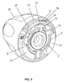
- La figure 5 est une vue en perspective montrant l'intérieur du mandrin de la figure 1, coupé transversalement selon la ligne AA, en position verrouillée ; et
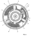
- Les figures 6 et 7 sont des vues en coupe, selon la ligne AA, du mandrin de la figure 1, respectivement en position déverrouillée et en position verrouillée.
- Figure 1 is a longitudinal sectional view of a mandrel according to the invention;
- Figure 2 is a perspective view of the body of the mandrel, placed around the central piece;
- Figure 3 is a perspective view of the clamping ring;
- Figure 4 is an elevational view of the locking finger;
- Figure 5 is a perspective view showing the inside of the mandrel of Figure 1, cut transversely along the line AA, in the locked position; and
- Figures 6 and 7 are sectional views, along the line AA, of the mandrel of Figure 1, respectively in the unlocked position and in the locked position.
Le mandrin 1 comprend tout d'abord une pièce centrale 2, d'axe 3, comportant une partie arrière 4 destinée à être fixée sur un arbre moteur de la machine tournante, une partie centrale 5 présentant une denture périphérique 6 orientée axialement, et une partie avant 7 présentant une forme tronconique convergeant vers l'avant, munie d'un filetage extérieur 8 à droite.The
Le mandrin 1 comprend également un corps 9 entourant la pièce centrale 2 et monté mobile en rotation par rapport à la pièce centrale 2. Le corps présente une enveloppe 10 sensiblement cylindrique d'axe 11, de laquelle font saillie globalement radialement trois logements 12 convergeant vers l'avant et sensiblement équirépartis sur la périphérie. De plus, une ouverture 13 est ménagée dans l'enveloppe 10 du corps 9, environ à un tiers de la distance radiale entre deux logements 12 adjacents. L'ouverture 13 est située en regard de la denture périphérique 6 de la pièce centrale 2, lorsque le corps 9 est monté sur la pièce centrale 2, et est délimitée par une paroi avant 14 et une paroi arrière orthogonales à l'axe 11 de l'enveloppe 10 et deux parois latérales 15 perpendiculaires aux parois avant 14 et arrière. Bien que d'autres réalisations puissent être envisagées, le corps 9 est ici formé à partir d'une tôle comprenant trois ailes repliées sur elles-mêmes, représentées avec des hachures différentes dans les vues en coupe (figures 6 et 7).The
Le mandrin 1 comprend en outre des mors 16, chacun étant monté et guidé en translation dans un logement 12 du corps 9. Chaque mors 16 comporte une denture 17 sur sa face intérieure, destinée à coopérer avec le filetage 8 de la pièce centrale 2.The
Une bague de serrage 18, d'axe 19, est montée autour du corps 9, en partie avant du mandrin 1, sensiblement coaxialement. La bague de serrage 18 comprend une enveloppe 20 en forme de dôme ouvert vers l'arrière, dont le diamètre intérieur est légèrement supérieur au diamètre extérieur des logements 12 tout le long de l'axe, afin que le corps 9 s'insère parfaitement dans la bague de serrage 18.A
A l'intérieur de l'enveloppe 20, à proximité de sa face intérieure et venus de matière avec elle, la bague de serrage 18 comporte trois organes 21, 22, 23 présentant en section une forme de portion de couronne coaxiale à l'enveloppe 20. Les organes 21, 22, 23 sont sensiblement équirépartis à la périphérie intérieure de l'enveloppe 20 et font saillie axialement vers l'arrière au-delà du bord arrière 24 de l'enveloppe 20.Inside the
Les organes 21, 22, 23 présentent une épaisseur radiale inférieure à la distance radiale entre la face intérieure de l'enveloppe 20 de la bague de serrage 18 et la face extérieure de l'enveloppe 10 du corps 9, à l'état monté, et une longueur circonférentielle inférieure à l'espacement circonférentiel entre deux logements 12 du corps 9. Par exemple, chaque organe 21, 22, 23 s'étend sur un arc de cercle d'environ 60 à 80°. Ainsi, à l'état monté autour du corps 9, la bague de serrage 18 peut pivoter autour du corps 9 selon une amplitude angulaire limitée, chaque organe 21, 22, 23 se déplaçant en rotation entre deux positions extrêmes définies par la butée contre un logement 12. L'amplitude de ce déplacement est par exemple de l'ordre de 20 à 40°.The
L'un des trois organes 21 comprend deux rainures 25 annulaires, pratiquées chacune depuis une extrémité circonférentielle de l'organe 21, sensiblement sur un même arc de cercle et au droit du bord arrière 24 de l'enveloppe 20, sur une distance inférieure à la moitié de la longueur circonférentielle de l'organe 21. Ainsi, la partie arrière de l'organe 21 forme une patte 26 en forme de portion de couronne, reliée à l'enveloppe 20 par un pont de matière 27. De plus, la patte 26 présente une échancrure réalisée depuis sa face intérieure, sensiblement centrée de façon circonférentielle, de sorte que la patte 26 présente à ses parties extrêmes circonférentielles deux ergots, respectivement un ergot de verrouillage 28 et un ergot de déverrouillage 29. L'ergot de verrouillage 28 présente une longueur circonférentielle plus importante que l'ergot de déverrouillage 29.One of the three
Du fait de sa longueur axiale réduite et de son rattachement à l'enveloppe 20 uniquement par le pont 27, la patte 26 peut être déformée élastiquement dans un plan transversal (orthogonal à l'axe du mandrin) de façon à rapprocher ou éloigner les ergots 28, 29 l'un de l'autre. Par ailleurs, le contour des ergots 28, 29 est arrondi afin de faciliter leur déplacement et leur glissement le long de différentes surfaces, comme on le verra plus loin.Because of its reduced axial length and its attachment to the
Un nez métallique 30 est en outre monté à l'intérieur de la bague de serrage 18. Le nez 30 fait en partie saillie à l'avant du mandrin 1 et est muni d'une ouverture centrale permettant le passage des mors 16 et de l'outil.A
Le mandrin 1 comprend également une bague arrière 31 engagée autour de la partie arrière 4 la pièce centrale 2 de façon sensiblement coaxiale. La bague arrière 31 et la bague de serrage 18 sont sensiblement adjacentes et de même diamètre dans leur zone d'adjacence, le mandrin 1 présentant ainsi une enveloppe latérale sensiblement continue. La bague arrière 31 comprend une partie cylindrique 32 engagée sur la partie arrière 4 de la pièce centrale 2, prolongée vers l'extérieur par une partie radiale 33 en forme d'anneau, elle-même prolongée vers l'extérieur par une jupe 34 sensiblement cylindrique. La partie arrière 4 de la pièce centrale 2 et la partie cylindrique 32 de la bague arrière comprennent des moyens réciproques de blocage en rotation et en translation axiale.The
Enfin, le mandrin 1 comprend un doigt de verrouillage 35 prévu pour être engagé dans l'ouverture 13 du corps 9. Le doigt de verrouillage 35 est formé à partir d'une plaque métallique par découpe ou emboutissage, et comprend une face avant et une face arrière 36 sensiblement planes et parallèles, espacées l'une de l'autre d'une distance sensiblement égale à la distance entre les parois avant 14 et arrière de l'ouverture 13. Ainsi, lorsque le doigt 35 est placé dans l'ouverture 13, ses faces avant et arrière 36 coopèrent avec les parois avant 14 et arrière de l'ouverture 13, ce qui assure la bonne tenue du doigt 35 dans un plan transversal à l'axe du mandrin 1.Finally, the
Le doigt de verrouillage 35 comprend une partie d'actionnement 37 allongée dont la face intérieure 38 est sensiblement plane et dont la face extérieure 39, globalement parallèle à la face intérieure 38, comprend deux échancrures en forme de portion de disque, formant l'une un logement de verrouillage 40 et l'autre un logement de déverrouillage 41. Les logements 40, 41 sont espacés l'un de l'autre selon une direction parallèle aux faces avant et arrière du doigt 35 d'une distance inférieure à la distance circonférentielle entre l'ergot de déverrouillage 29 et l'ergot de verrouillage 28.The locking
Afin de simplifier la description, on utilisera les termes « amont » et « aval » qui désignent chacun un côté du doigt de verrouillage 35, lorsqu'il est vu depuis sa face arrière 36, respectivement le côté du logement de déverrouillage 41 et le côté du logement de verrouillage 40.In order to simplify the description, use will be made of the terms "upstream" and "downstream", each of which designates one side of the locking
La face amont 42 et la face aval 43 de la partie d'actionnement 37 du doigt de verrouillage 35 sont bombées et définissent des rampes de glissement des ergots de verrouillage 28 et de déverrouillage 29 comme on le verra plus loin.The
Le doigt de verrouillage 35 comprend en outre une partie de blocage 44 faisant saillie sensiblement perpendiculairement de la face intérieure 38 de la partie d'actionnement 37, de façon non centrée mais décalée vers l'aval. La partie de blocage 44 comprend une face aval 45 bombée formant un patin de glissement, située sensiblement au droit du logement de verrouillage 40. La face amont 46 comprend une première portion incurvée formant un renfoncement 47 dans lequel se situe l'axe fictif 48 du congé de raccordement 49 en portion de cylindre entre la face amont 46 de la partie de blocage 44 et la face intérieure 38 de la partie d'actionnement 37. La face amont 46 présente ensuite une portion bombée formée par un sabot 50 faisant saillie vers l'amont sensiblement parallèlement à la partie d'actionnement 37 et au moins en partie en regard de celle-ci. La partie de blocage 44 présente ainsi sensiblement la forme d'un crochet recourbé vers l'amont.The locking
Enfin, la partie extrême libre de la partie de blocage 44 se présente sous la forme d'une dent 51 comprenant en amont une face d'échappement 52 et en aval une face de blocage 53.Finally, the free end portion of the locking
Lors du montage du mandrin 1, la partie de blocage 44 du doigt de verrouillage 35 est engagée dans l'ouverture 13 du corps 9, la face intérieure 38 de la partie d'actionnement 37 venant en contact avec la face extérieure de l'enveloppe 10 du corps 9. Puis la bague de serrage 18 est engagée autour du corps 9 et du doigt de verrouillage 35, de façon que la patte 26 soit située entre les deux mêmes logements 12 que le doigt de verrouillage 35.During assembly of the
Le fonctionnement du mandrin 1 est le suivant.The operation of
Initialement, les différents éléments constitutifs du mandrin 1 sont dans la position de la figure 6, à savoir la position déverrouillée, dans laquelle le doit de déverrouillage 29 est placé dans le logement de déverrouillage 41, le doigt de verrouillage 35 n'étant pas en contact avec la denture périphérique 6 de la pièce centrale 2. L'ergot de verrouillage 28 est alors en butée contre le logement 12 situé en aval du doigt de verrouillage 35.Initially, the various components of the
Pour le déplacement des mors 16 vers la position de serrage d'un outil, la bague de serrage 18 est mise en rotation par rapport à la pièce centrale 2 dans le sens inverse des aiguilles d'une montre (selon la vue de la figure 6). L'ergot de déverrouillage 29 reste placé dans le logement de déverrouillage 41 et entraîne de ce fait le corps 9 en rotation autour de la pièce centrale 2, via le doigt de verrouillage 35. Puisque le doigt de verrouillage 35 n'est toujours pas en contact avec la denture périphérique 6, il ne s'oppose pas à la rotation relative de l'ensemble bague de serrage 18 - corps 9 par rapport à la pièce centrale 2. Les mors 16, du fait de la coopération entre leur denture 17 et le filetage 8 de la pièce centrale 2, sont déplacés dans les logement 12 du corps 9 vers l'avant du mandrin 1 et rapprochés les uns des autres.For the movement of the
Lorsque les mors 16 arrivent en contact avec l'outil à serrer, la résistance du corps 9 à l'encontre de l'entraînement en rotation par la bague de serrage 18 augmente. De ce fait, lorsque l'on poursuit le mouvement de rotation, l'ergot de déverrouillage 29 s'échappe du logement de déverrouillage 41 et l'ergot de verrouillage 28 est rapproché de la face aval 43 de la partie d'actionnement 37 du doigt de verrouillage 35 contre laquelle il vient glisser, avant de venir se placer dans le logement de verrouillage 40 en entraînant le pivotement du doigt de verrouillage 35 autour de l'axe fictif 48. Ce déplacement de l'ergot de verrouillage 28 est rendu possible par l'élasticité de la patte 26, comme expliqué plus haut.When the
Dans cette position, dite de verrouillage (figure 7), l'ergot de déverrouillage 29 est en butée contre le logement 12 situé en amont du doigt de verrouillage 35, et la dent 51 est engagée dans la denture périphérique 6 de la pièce centrale 2.In this position, called locking (Figure 7), the
Lorsque la pièce centrale 2 est mise en rotation dans le sens des aiguilles d'une montre (« rotation à droite »), le mandrin 1 a naturellement tendance à se resserrer. La denture périphérique 6 de la pièce centrale 2 vient pousser sur la face d'échappement 52 de la dent 51 selon une direction sensiblement normale à cette face. Par leur structure, le congé de raccordement 49 et le patin de glissement 45 autorisent un mouvement de pivotement du doigt de verrouillage 35 par rapport au corps 9, dans un plan transversal, centré sur l'axe fictif 48. Ce pivotement est également rendu possible par les dimensions relatives de l'ouverture 13 et de la partie de blocage 44 du doigt de verrouillage 35.When the
Le doigt de verrouillage 35 peut donc pivoter dans le sens inverse des aiguilles d'une montre, ce mouvement étant limité par le doigt de verrouillage 28 lié à la patte 26 déformable élastiquement. Il s'ensuit que le doigt de verrouillage 35 est animé d'un mouvement de pivotement alternatif dans un plan transversal, à la manière d'un cliquet d'un système de roue à rochet, et génère un son caractéristique de cliquetis.The locking
A l'inverse, si la pièce centrale 2 est mise en rotation dans le sens inverse des aiguilles d'une montre (« rotation à gauche »), le mandrin 1 a naturellement tendance à se desserrer. La denture périphérique 6 de la pièce centrale 2 vient pousser sur la face de blocage 53 de la dent 51 selon une direction sensiblement normale à cette face. En conséquence, le doigt de verrouillage 35 est contraint de pivoter dans le sens des aiguilles d'une montre vers une position de blocage dans laquelle le sabot 50 est plaqué contre la face intérieure du corps 9. De ce fait, l'ensemble pièce centrale 2 - doigt de verrouillage 35 - corps 9 - bague de serrage 18 est rendu solidaire en rotation, dans le sens inverse des aiguilles d'une montre, ce qui évite le desserrage des mors 16.Conversely, if the
Pour procéder au déverrouillage et à l'ouverture du mandrin 1, il suffit d'entraîner la bague de serrage 18 en rotation dans le sens des aiguilles d'une montre, par rapport à la pièce centrale 2, depuis la position de verrouillage vers la position de déverrouillage.To unlock and open the
Au cours de ce mouvement, l'ergot de verrouillage 28 quitte le logement de verrouillage 40, puis l'ergot de déverrouillage prend position dans le logement de déverrouillage 41, en provoquant le pivotement du doigt de verrouillage 35 autour de l'axe fictif 48, la dent 51 quittant donc le contact de la denture périphérique 6 de la pièce centrale 2. La bague de serrage 18 peut alors entraîner librement le corps 9 en rotation dans le sens des aiguilles d'une montre, les mors 16 étant déplacés vers la position desserrée où ils sont rétractés à l'intérieur du mandrin 1 et écartés les uns des autres, l'outil pouvant alors être ôté du mandrin 1.During this movement, the locking
Il va de soi que l'invention n'est pas limitée à la forme de réalisation décrite ci-dessus à titre d'exemple mais qu'elle en embrasse au contraire toutes les variantes de réalisation. L'invention peut notamment être mise en oeuvre dans des mandrins dans lesquels les mors sont entraînés par un écrou périphérique.It goes without saying that the invention is not limited to the embodiment described above by way of example but that it encompasses all variants. The invention can in particular be implemented in mandrels in which the jaws are driven by a peripheral nut.
Claims (9)
Applications Claiming Priority (1)
| Application Number | Priority Date | Filing Date | Title |
|---|---|---|---|
| FR0502587A FR2883208B1 (en) | 2005-03-16 | 2005-03-16 | TOOL HOLDER CHUCK FOR ROTATING MACHINE HAVING LOCKING MEANS |
Publications (2)
| Publication Number | Publication Date |
|---|---|
| EP1702694A1 true EP1702694A1 (en) | 2006-09-20 |
| EP1702694B1 EP1702694B1 (en) | 2008-05-07 |
Family
ID=35229958
Family Applications (1)
| Application Number | Title | Priority Date | Filing Date |
|---|---|---|---|
| EP06356023A Not-in-force EP1702694B1 (en) | 2005-03-16 | 2006-03-09 | Tool chuck for rotating machine, provided with locking means |
Country Status (7)
| Country | Link |
|---|---|
| US (1) | US7556269B2 (en) |
| EP (1) | EP1702694B1 (en) |
| CN (1) | CN100562390C (en) |
| AT (1) | ATE394182T1 (en) |
| DE (1) | DE602006001062D1 (en) |
| ES (1) | ES2308702T3 (en) |
| FR (1) | FR2883208B1 (en) |
Families Citing this family (8)
| Publication number | Priority date | Publication date | Assignee | Title |
|---|---|---|---|---|
| FR2883209B1 (en) * | 2005-03-16 | 2007-05-11 | Amyot Sa Sa Ets | TOOL HOLDER CHUCK FOR THE EQUIPMENT OF A ROTATING MACHINE |
| FR2886183B1 (en) * | 2005-05-27 | 2007-07-13 | Amyot Sa Sa Ets | TOOL HOLDER CHUCK FOR THE EQUIPMENT OF A ROTATING MACHINE, IN PARTICULAR OF THE "SHOCK KEY" TYPE |
| US7896356B2 (en) * | 2006-04-10 | 2011-03-01 | Shandong Weida Machinery Co., Ltd. | Drill chuck with two-stage gripping |
| FR2941395B1 (en) | 2009-01-26 | 2014-10-10 | Amyot Ets Sa | TOOL HOLDER CHUCK FOR THE EQUIPMENT OF A ROTATING MACHINE. |
| FR2956051B1 (en) | 2010-02-08 | 2012-03-02 | Amyot Ets Sa | TOOL HOLDER CHUCK FOR THE EQUIPMENT OF A ROTATING MACHINE |
| US8616561B2 (en) * | 2012-04-10 | 2013-12-31 | Apex Brands, Inc. | Locking chuck |
| DE102013214019B3 (en) * | 2013-07-17 | 2014-09-11 | Trumpf Werkzeugmaschinen Gmbh + Co. Kg | Clamping device for positioning workpieces, machine tool with such a clamping device, method for positioning workpieces by means of such a clamping device |
| WO2016057886A1 (en) * | 2014-10-10 | 2016-04-14 | Apex Brands, Inc. | Locking chuck |
Citations (9)
| Publication number | Priority date | Publication date | Assignee | Title |
|---|---|---|---|---|
| US4302021A (en) * | 1979-04-14 | 1981-11-24 | Roehm Guenter H | Nonloosening chuck |
| EP0335593A2 (en) * | 1988-03-28 | 1989-10-04 | Matsushita Electric Works, Ltd. | Keyless chuck for rotary tool |
| EP0590754A1 (en) * | 1992-09-28 | 1994-04-06 | Pi-Chu Lin | Chuck assembly for a drilling apparatus |
| EP0864390A2 (en) * | 1997-03-14 | 1998-09-16 | Röhm GmbH | Drill chuck |
| US6007071A (en) * | 1998-03-09 | 1999-12-28 | Power Tool Holders Incorporated | Chuck with locking body |
| EP1314499A1 (en) * | 2001-11-21 | 2003-05-28 | Metabowerke GmbH | Keyless chuck |
| US20030141676A1 (en) * | 2002-01-31 | 2003-07-31 | Yukiwa Seiko Kabushiki Kaisha | Chuck device |
| US20040217558A1 (en) * | 2001-06-10 | 2004-11-04 | Guimo Yang | Chuck |
| US20040227309A1 (en) * | 2003-05-14 | 2004-11-18 | Rohm Gmbh & Co. Kg | Fast-action drill chuck |
Family Cites Families (16)
| Publication number | Priority date | Publication date | Assignee | Title |
|---|---|---|---|---|
| US573189A (en) * | 1896-12-15 | Ernest ii | ||
| DE7804747U1 (en) * | 1978-02-17 | 1978-06-15 | Roehm, Guenter Horst, 7927 Sontheim | CHUCK |
| DE3713457C1 (en) * | 1987-04-22 | 1988-09-15 | Roehm Guenter H | Retightening drill chuck |
| DE4238464C1 (en) * | 1992-11-16 | 1994-03-03 | Roehm Guenter H | Self-tightening drill chuck |
| FR2702975B1 (en) * | 1993-03-26 | 1995-06-16 | Amyot Ets Sa | TOOL HOLDER CHUCK FOR THE EQUIPMENT OF A ROTATING MACHINE, SUCH AS A DRILL. |
| US5741016A (en) * | 1996-10-02 | 1998-04-21 | Power Tool Holders Incorporated | Chuck |
| US6007701A (en) * | 1999-02-16 | 1999-12-28 | Miami University | Method of removing contaminants from used oil |
| DE10101212A1 (en) * | 2001-01-11 | 2002-07-18 | Roehm Gmbh | chuck |
| JP2003071618A (en) * | 2001-08-30 | 2003-03-12 | Yukiwa Seiko Inc | Chuck device |
| FR2847180B1 (en) * | 2002-11-18 | 2005-02-11 | Amyot Ets Sa | TOOL HOLDER MECHANISM WITH LATCHING SYSTEM |
| CN2582790Y (en) * | 2002-11-25 | 2003-10-29 | 山东威达机械股份有限公司 | Self-locking drill chuck |
| US7258351B2 (en) * | 2003-04-04 | 2007-08-21 | Robert Bosch Gmbh | Quick-action chuck |
| CN101142047B (en) * | 2005-03-19 | 2011-06-08 | 罗姆股份有限公司 | Drill chuck |
| DE102005018392B4 (en) * | 2005-04-20 | 2019-10-31 | Röhm Gmbh | chuck |
| FR2897789B1 (en) * | 2006-02-27 | 2008-05-09 | Amyot Sa Sa Ets | TOOL HOLDER CHUCK FOR THE EQUIPMENT OF A ROTATING MACHINE WITH RADIAL LOCKING AND AXIAL SEQUENCE MECHANISMS |
| DE102006011344A1 (en) * | 2006-03-11 | 2007-09-13 | Röhm Gmbh | Drill chuck, has rotating bush supported at axially rear end of chuck body and coupled with part of web retainer or locking device in torque transferable manner, where web retainer is utilized for actuating clamping jaw |
-
2005
- 2005-03-16 FR FR0502587A patent/FR2883208B1/en not_active Expired - Fee Related
-
2006
- 2006-02-28 US US11/362,785 patent/US7556269B2/en not_active Expired - Fee Related
- 2006-03-09 DE DE602006001062T patent/DE602006001062D1/en active Active
- 2006-03-09 ES ES06356023T patent/ES2308702T3/en active Active
- 2006-03-09 EP EP06356023A patent/EP1702694B1/en not_active Not-in-force
- 2006-03-09 AT AT06356023T patent/ATE394182T1/en not_active IP Right Cessation
- 2006-03-16 CN CNB2006100717382A patent/CN100562390C/en not_active Expired - Fee Related
Patent Citations (9)
| Publication number | Priority date | Publication date | Assignee | Title |
|---|---|---|---|---|
| US4302021A (en) * | 1979-04-14 | 1981-11-24 | Roehm Guenter H | Nonloosening chuck |
| EP0335593A2 (en) * | 1988-03-28 | 1989-10-04 | Matsushita Electric Works, Ltd. | Keyless chuck for rotary tool |
| EP0590754A1 (en) * | 1992-09-28 | 1994-04-06 | Pi-Chu Lin | Chuck assembly for a drilling apparatus |
| EP0864390A2 (en) * | 1997-03-14 | 1998-09-16 | Röhm GmbH | Drill chuck |
| US6007071A (en) * | 1998-03-09 | 1999-12-28 | Power Tool Holders Incorporated | Chuck with locking body |
| US20040217558A1 (en) * | 2001-06-10 | 2004-11-04 | Guimo Yang | Chuck |
| EP1314499A1 (en) * | 2001-11-21 | 2003-05-28 | Metabowerke GmbH | Keyless chuck |
| US20030141676A1 (en) * | 2002-01-31 | 2003-07-31 | Yukiwa Seiko Kabushiki Kaisha | Chuck device |
| US20040227309A1 (en) * | 2003-05-14 | 2004-11-18 | Rohm Gmbh & Co. Kg | Fast-action drill chuck |
Also Published As
| Publication number | Publication date |
|---|---|
| US7556269B2 (en) | 2009-07-07 |
| EP1702694B1 (en) | 2008-05-07 |
| US20070252345A1 (en) | 2007-11-01 |
| DE602006001062D1 (en) | 2008-06-19 |
| FR2883208A1 (en) | 2006-09-22 |
| FR2883208B1 (en) | 2007-05-11 |
| CN100562390C (en) | 2009-11-25 |
| CN1951614A (en) | 2007-04-25 |
| ATE394182T1 (en) | 2008-05-15 |
| ES2308702T3 (en) | 2008-12-01 |
Similar Documents
| Publication | Publication Date | Title |
|---|---|---|
| EP1702694B1 (en) | Tool chuck for rotating machine, provided with locking means | |
| CA2679079C (en) | Tightening device with swivelling handling arm and applicance including such a device | |
| EP1419837B1 (en) | Tool holder with locking system | |
| FR2897789A1 (en) | TOOL HOLDER CHUCK FOR THE EQUIPMENT OF A ROTATING MACHINE WITH RADIAL LOCKING AND AXIAL SEQUENCE MECHANISMS | |
| EP2389264B1 (en) | Tool holder mandrel for equipping a rotating machine | |
| FR2898821A1 (en) | AUTOSERRANT HOLDER CHUCK | |
| FR2727045A1 (en) | Turn lock for drive shaft of cutting blade of free=cutting unit | |
| CA2780167A1 (en) | Self-locking screwing attachment device and assembly provided with same | |
| FR2857080A1 (en) | Locking device for channel connector, has ratchet type teeth permitting rotation of male and female units with respect to one another relative to unscrewing direction when predetermined elastic resistance of compression spring is overcome | |
| FR2881368A1 (en) | DEVICE FOR ADJUSTING THE SOLE OF A JIGSAW SAW | |
| CH707490A1 (en) | torque wrench. | |
| EP1815926A2 (en) | Tool chuck for equipping a rotating machine | |
| EP1702693B1 (en) | Tool chuck for a rotating machine | |
| EP1883486B1 (en) | Tool-holder chuck for equipping a rotating machine, in particular of the impact wrench type | |
| FR2623431A1 (en) | TIGHTENING CHUCK FOR MACHINE TOOL | |
| EP0227511B1 (en) | Device to clamp at least two parts side by side to be jointed, and a clamping unit comprising a clamping tool and said clamping device | |
| EP1858665A1 (en) | Tool-holder mandrel for equipping a rotating machine | |
| FR2920104A1 (en) | Tool holder chuck for e.g. impact drill, has displacement unit that is formed by stud and ramp and moving cylindrical sleeve outside of locking position of sleeve during application of torque greater than predetermined value | |
| FR2891757A1 (en) | CHUCK WITH STOP OF GRIPPING MECHANISM | |
| FR2956051A1 (en) | TOOL HOLDER CHUCK FOR THE EQUIPMENT OF A ROTATING MACHINE | |
| EP0953778A1 (en) | Quick-mounting nut composed of two half-nuts, and fastening device in particular for concrete formwork using such a nut | |
| FR2883210A1 (en) | Mandrel for holding tool, e.g. drill bit, for turning machine, includes central piece having holding jaws and rear operating collar with blocked relative rotation and axial translation | |
| FR2543628A1 (en) | Device for the blind stapling of two components, especially for motor vehicle metal sheets | |
| WO2007006108A1 (en) | Quick-release assembly | |
| FR2907354A1 (en) | Tool holder mandrel for e.g. drilling machine equipment, has lock washer buttressed on cylindrical part to avoid backward movement of bits, and projected part provided between ring and washer for realizing buttressing of washer |
Legal Events
| Date | Code | Title | Description |
|---|---|---|---|
| PUAI | Public reference made under article 153(3) epc to a published international application that has entered the european phase |
Free format text: ORIGINAL CODE: 0009012 |
|
| AK | Designated contracting states |
Kind code of ref document: A1 Designated state(s): AT BE BG CH CY CZ DE DK EE ES FI FR GB GR HU IE IS IT LI LT LU LV MC NL PL PT RO SE SI SK TR |
|
| AX | Request for extension of the european patent |
Extension state: AL BA HR MK YU |
|
| 17P | Request for examination filed |
Effective date: 20061204 |
|
| AKX | Designation fees paid |
Designated state(s): AT BE BG CH CY CZ DE DK EE ES FI FR GB GR HU IE IS IT LI LT LU LV MC NL PL PT RO SE SI SK TR |
|
| GRAP | Despatch of communication of intention to grant a patent |
Free format text: ORIGINAL CODE: EPIDOSNIGR1 |
|
| GRAS | Grant fee paid |
Free format text: ORIGINAL CODE: EPIDOSNIGR3 |
|
| GRAA | (expected) grant |
Free format text: ORIGINAL CODE: 0009210 |
|
| AK | Designated contracting states |
Kind code of ref document: B1 Designated state(s): AT BE BG CH CY CZ DE DK EE ES FI FR GB GR HU IE IS IT LI LT LU LV MC NL PL PT RO SE SI SK TR |
|
| REG | Reference to a national code |
Ref country code: GB Ref legal event code: FG4D Free format text: NOT ENGLISH |
|
| REG | Reference to a national code |
Ref country code: CH Ref legal event code: EP |
|
| REG | Reference to a national code |
Ref country code: IE Ref legal event code: FG4D |
|
| REF | Corresponds to: |
Ref document number: 602006001062 Country of ref document: DE Date of ref document: 20080619 Kind code of ref document: P |
|
| PG25 | Lapsed in a contracting state [announced via postgrant information from national office to epo] |
Ref country code: SI Free format text: LAPSE BECAUSE OF FAILURE TO SUBMIT A TRANSLATION OF THE DESCRIPTION OR TO PAY THE FEE WITHIN THE PRESCRIBED TIME-LIMIT Effective date: 20080507 |
|
| PG25 | Lapsed in a contracting state [announced via postgrant information from national office to epo] |
Ref country code: FI Free format text: LAPSE BECAUSE OF FAILURE TO SUBMIT A TRANSLATION OF THE DESCRIPTION OR TO PAY THE FEE WITHIN THE PRESCRIBED TIME-LIMIT Effective date: 20080507 |
|
| PG25 | Lapsed in a contracting state [announced via postgrant information from national office to epo] |
Ref country code: LV Free format text: LAPSE BECAUSE OF FAILURE TO SUBMIT A TRANSLATION OF THE DESCRIPTION OR TO PAY THE FEE WITHIN THE PRESCRIBED TIME-LIMIT Effective date: 20080507 Ref country code: PL Free format text: LAPSE BECAUSE OF FAILURE TO SUBMIT A TRANSLATION OF THE DESCRIPTION OR TO PAY THE FEE WITHIN THE PRESCRIBED TIME-LIMIT Effective date: 20080507 Ref country code: AT Free format text: LAPSE BECAUSE OF FAILURE TO SUBMIT A TRANSLATION OF THE DESCRIPTION OR TO PAY THE FEE WITHIN THE PRESCRIBED TIME-LIMIT Effective date: 20080507 |
|
| REG | Reference to a national code |
Ref country code: ES Ref legal event code: FG2A Ref document number: 2308702 Country of ref document: ES Kind code of ref document: T3 |
|
| REG | Reference to a national code |
Ref country code: IE Ref legal event code: FD4D |
|
| PG25 | Lapsed in a contracting state [announced via postgrant information from national office to epo] |
Ref country code: IS Free format text: LAPSE BECAUSE OF FAILURE TO SUBMIT A TRANSLATION OF THE DESCRIPTION OR TO PAY THE FEE WITHIN THE PRESCRIBED TIME-LIMIT Effective date: 20080907 |
|
| PG25 | Lapsed in a contracting state [announced via postgrant information from national office to epo] |
Ref country code: SE Free format text: LAPSE BECAUSE OF FAILURE TO SUBMIT A TRANSLATION OF THE DESCRIPTION OR TO PAY THE FEE WITHIN THE PRESCRIBED TIME-LIMIT Effective date: 20080807 Ref country code: IE Free format text: LAPSE BECAUSE OF FAILURE TO SUBMIT A TRANSLATION OF THE DESCRIPTION OR TO PAY THE FEE WITHIN THE PRESCRIBED TIME-LIMIT Effective date: 20080507 Ref country code: CZ Free format text: LAPSE BECAUSE OF FAILURE TO SUBMIT A TRANSLATION OF THE DESCRIPTION OR TO PAY THE FEE WITHIN THE PRESCRIBED TIME-LIMIT Effective date: 20080507 Ref country code: DK Free format text: LAPSE BECAUSE OF FAILURE TO SUBMIT A TRANSLATION OF THE DESCRIPTION OR TO PAY THE FEE WITHIN THE PRESCRIBED TIME-LIMIT Effective date: 20080507 Ref country code: LT Free format text: LAPSE BECAUSE OF FAILURE TO SUBMIT A TRANSLATION OF THE DESCRIPTION OR TO PAY THE FEE WITHIN THE PRESCRIBED TIME-LIMIT Effective date: 20080507 |
|
| PLBI | Opposition filed |
Free format text: ORIGINAL CODE: 0009260 |
|
| PG25 | Lapsed in a contracting state [announced via postgrant information from national office to epo] |
Ref country code: PT Free format text: LAPSE BECAUSE OF FAILURE TO SUBMIT A TRANSLATION OF THE DESCRIPTION OR TO PAY THE FEE WITHIN THE PRESCRIBED TIME-LIMIT Effective date: 20081007 Ref country code: RO Free format text: LAPSE BECAUSE OF FAILURE TO SUBMIT A TRANSLATION OF THE DESCRIPTION OR TO PAY THE FEE WITHIN THE PRESCRIBED TIME-LIMIT Effective date: 20080507 Ref country code: SK Free format text: LAPSE BECAUSE OF FAILURE TO SUBMIT A TRANSLATION OF THE DESCRIPTION OR TO PAY THE FEE WITHIN THE PRESCRIBED TIME-LIMIT Effective date: 20080507 |
|
| PLAX | Notice of opposition and request to file observation + time limit sent |
Free format text: ORIGINAL CODE: EPIDOSNOBS2 |
|
| 26 | Opposition filed |
Opponent name: ROEHM GMBH Effective date: 20090123 |
|
| PG25 | Lapsed in a contracting state [announced via postgrant information from national office to epo] |
Ref country code: EE Free format text: LAPSE BECAUSE OF FAILURE TO SUBMIT A TRANSLATION OF THE DESCRIPTION OR TO PAY THE FEE WITHIN THE PRESCRIBED TIME-LIMIT Effective date: 20080507 Ref country code: BG Free format text: LAPSE BECAUSE OF FAILURE TO SUBMIT A TRANSLATION OF THE DESCRIPTION OR TO PAY THE FEE WITHIN THE PRESCRIBED TIME-LIMIT Effective date: 20080807 |
|
| NLR1 | Nl: opposition has been filed with the epo |
Opponent name: ROEHM GMBH |
|
| PLAF | Information modified related to communication of a notice of opposition and request to file observations + time limit |
Free format text: ORIGINAL CODE: EPIDOSCOBS2 |
|
| BERE | Be: lapsed |
Owner name: ETS AMYOT S.A. Effective date: 20090331 |
|
| PLBB | Reply of patent proprietor to notice(s) of opposition received |
Free format text: ORIGINAL CODE: EPIDOSNOBS3 |
|
| PG25 | Lapsed in a contracting state [announced via postgrant information from national office to epo] |
Ref country code: MC Free format text: LAPSE BECAUSE OF NON-PAYMENT OF DUE FEES Effective date: 20090331 |
|
| REG | Reference to a national code |
Ref country code: FR Ref legal event code: ST Effective date: 20091130 |
|
| PG25 | Lapsed in a contracting state [announced via postgrant information from national office to epo] |
Ref country code: BE Free format text: LAPSE BECAUSE OF NON-PAYMENT OF DUE FEES Effective date: 20090331 |
|
| PG25 | Lapsed in a contracting state [announced via postgrant information from national office to epo] |
Ref country code: FR Free format text: LAPSE BECAUSE OF NON-PAYMENT OF DUE FEES Effective date: 20091123 |
|
| REG | Reference to a national code |
Ref country code: ES Ref legal event code: FD2A Effective date: 20090310 |
|
| REG | Reference to a national code |
Ref country code: FR Ref legal event code: RN |
|
| PG25 | Lapsed in a contracting state [announced via postgrant information from national office to epo] |
Ref country code: ES Free format text: LAPSE BECAUSE OF NON-PAYMENT OF DUE FEES Effective date: 20090310 |
|
| PLCK | Communication despatched that opposition was rejected |
Free format text: ORIGINAL CODE: EPIDOSNREJ1 |
|
| PG25 | Lapsed in a contracting state [announced via postgrant information from national office to epo] |
Ref country code: GR Free format text: LAPSE BECAUSE OF FAILURE TO SUBMIT A TRANSLATION OF THE DESCRIPTION OR TO PAY THE FEE WITHIN THE PRESCRIBED TIME-LIMIT Effective date: 20080808 |
|
| REG | Reference to a national code |
Ref country code: FR Ref legal event code: IC |
|
| PLBN | Opposition rejected |
Free format text: ORIGINAL CODE: 0009273 |
|
| STAA | Information on the status of an ep patent application or granted ep patent |
Free format text: STATUS: OPPOSITION REJECTED |
|
| 27O | Opposition rejected |
Effective date: 20100621 |
|
| PG25 | Lapsed in a contracting state [announced via postgrant information from national office to epo] |
Ref country code: LU Free format text: LAPSE BECAUSE OF NON-PAYMENT OF DUE FEES Effective date: 20090309 |
|
| PG25 | Lapsed in a contracting state [announced via postgrant information from national office to epo] |
Ref country code: HU Free format text: LAPSE BECAUSE OF FAILURE TO SUBMIT A TRANSLATION OF THE DESCRIPTION OR TO PAY THE FEE WITHIN THE PRESCRIBED TIME-LIMIT Effective date: 20081108 |
|
| PG25 | Lapsed in a contracting state [announced via postgrant information from national office to epo] |
Ref country code: TR Free format text: LAPSE BECAUSE OF FAILURE TO SUBMIT A TRANSLATION OF THE DESCRIPTION OR TO PAY THE FEE WITHIN THE PRESCRIBED TIME-LIMIT Effective date: 20080507 |
|
| PG25 | Lapsed in a contracting state [announced via postgrant information from national office to epo] |
Ref country code: CY Free format text: LAPSE BECAUSE OF FAILURE TO SUBMIT A TRANSLATION OF THE DESCRIPTION OR TO PAY THE FEE WITHIN THE PRESCRIBED TIME-LIMIT Effective date: 20080507 |
|
| PGFP | Annual fee paid to national office [announced via postgrant information from national office to epo] |
Ref country code: CH Payment date: 20120215 Year of fee payment: 7 |
|
| PGFP | Annual fee paid to national office [announced via postgrant information from national office to epo] |
Ref country code: NL Payment date: 20120222 Year of fee payment: 7 |
|
| REG | Reference to a national code |
Ref country code: NL Ref legal event code: V1 Effective date: 20131001 |
|
| REG | Reference to a national code |
Ref country code: CH Ref legal event code: PL |
|
| PG25 | Lapsed in a contracting state [announced via postgrant information from national office to epo] |
Ref country code: CH Free format text: LAPSE BECAUSE OF NON-PAYMENT OF DUE FEES Effective date: 20130331 Ref country code: LI Free format text: LAPSE BECAUSE OF NON-PAYMENT OF DUE FEES Effective date: 20130331 |
|
| PG25 | Lapsed in a contracting state [announced via postgrant information from national office to epo] |
Ref country code: NL Free format text: LAPSE BECAUSE OF NON-PAYMENT OF DUE FEES Effective date: 20131001 |
|
| PGFP | Annual fee paid to national office [announced via postgrant information from national office to epo] |
Ref country code: DE Payment date: 20140317 Year of fee payment: 9 |
|
| PGFP | Annual fee paid to national office [announced via postgrant information from national office to epo] |
Ref country code: IT Payment date: 20140318 Year of fee payment: 9 |
|
| PGFP | Annual fee paid to national office [announced via postgrant information from national office to epo] |
Ref country code: GB Payment date: 20140314 Year of fee payment: 9 |
|
| REG | Reference to a national code |
Ref country code: DE Ref legal event code: R119 Ref document number: 602006001062 Country of ref document: DE |
|
| GBPC | Gb: european patent ceased through non-payment of renewal fee |
Effective date: 20150309 |
|
| PG25 | Lapsed in a contracting state [announced via postgrant information from national office to epo] |
Ref country code: IT Free format text: LAPSE BECAUSE OF NON-PAYMENT OF DUE FEES Effective date: 20150309 |
|
| PG25 | Lapsed in a contracting state [announced via postgrant information from national office to epo] |
Ref country code: GB Free format text: LAPSE BECAUSE OF NON-PAYMENT OF DUE FEES Effective date: 20150309 Ref country code: DE Free format text: LAPSE BECAUSE OF NON-PAYMENT OF DUE FEES Effective date: 20151001 |