EP1702663A1 - Endscheibe für ein Filtermedium - Google Patents
Endscheibe für ein Filtermedium Download PDFInfo
- Publication number
- EP1702663A1 EP1702663A1 EP06110734A EP06110734A EP1702663A1 EP 1702663 A1 EP1702663 A1 EP 1702663A1 EP 06110734 A EP06110734 A EP 06110734A EP 06110734 A EP06110734 A EP 06110734A EP 1702663 A1 EP1702663 A1 EP 1702663A1
- Authority
- EP
- European Patent Office
- Prior art keywords
- end plate
- rubber ring
- blank
- rubber
- plate according
- Prior art date
- Legal status (The legal status is an assumption and is not a legal conclusion. Google has not performed a legal analysis and makes no representation as to the accuracy of the status listed.)
- Granted
Links
Images

Classifications
-
- B—PERFORMING OPERATIONS; TRANSPORTING
- B01—PHYSICAL OR CHEMICAL PROCESSES OR APPARATUS IN GENERAL
- B01D—SEPARATION
- B01D29/00—Filters with filtering elements stationary during filtration, e.g. pressure or suction filters, not covered by groups B01D24/00 - B01D27/00; Filtering elements therefor
- B01D29/11—Filters with filtering elements stationary during filtration, e.g. pressure or suction filters, not covered by groups B01D24/00 - B01D27/00; Filtering elements therefor with bag, cage, hose, tube, sleeve or like filtering elements
- B01D29/111—Making filtering elements
-
- B—PERFORMING OPERATIONS; TRANSPORTING
- B01—PHYSICAL OR CHEMICAL PROCESSES OR APPARATUS IN GENERAL
- B01D—SEPARATION
- B01D29/00—Filters with filtering elements stationary during filtration, e.g. pressure or suction filters, not covered by groups B01D24/00 - B01D27/00; Filtering elements therefor
- B01D29/11—Filters with filtering elements stationary during filtration, e.g. pressure or suction filters, not covered by groups B01D24/00 - B01D27/00; Filtering elements therefor with bag, cage, hose, tube, sleeve or like filtering elements
- B01D29/13—Supported filter elements
- B01D29/15—Supported filter elements arranged for inward flow filtration
- B01D29/21—Supported filter elements arranged for inward flow filtration with corrugated, folded or wound sheets
-
- B—PERFORMING OPERATIONS; TRANSPORTING
- B01—PHYSICAL OR CHEMICAL PROCESSES OR APPARATUS IN GENERAL
- B01D—SEPARATION
- B01D2201/00—Details relating to filtering apparatus
- B01D2201/29—Filter cartridge constructions
- B01D2201/291—End caps
- B01D2201/293—Making of end caps
-
- B—PERFORMING OPERATIONS; TRANSPORTING
- B01—PHYSICAL OR CHEMICAL PROCESSES OR APPARATUS IN GENERAL
- B01D—SEPARATION
- B01D2201/00—Details relating to filtering apparatus
- B01D2201/34—Seals or gaskets for filtering elements
Definitions
- the invention relates to an end plate for a filter medium according to the preamble of claim 1. Furthermore, the invention relates to two production methods according to claims 7 and 8 and a filter element according to claim 9.
- End discs for filter media have the task of sealing the fluid-permeable filter media on the end faces sealing.
- the end plates create connection openings which separate a raw side from a clean side. Through these connection openings, the end plates must be releasably and sealingly connected to a connection element.
- a connection element is for example from the DE 198 13 319 known.
- a rubber ring is molded onto a thermoplastic end disk of a filter on one end face. This should ensure easy installation of the filter and achieve a reliable seal.
- the disadvantage here is that recording contours have been arranged for receiving the rubber ring on the end plate, which project beyond the filter in axial length. The injected rubber element in turn projects beyond the receiving contours, whereby a considerable installation space for the end plate is required.
- the object of the invention is to provide an end plate for a filter element, which allows a reliable seal and easy installation. Furthermore, the end plate should be simple and economically advantageous to produce.
- the end plate according to the invention is preferably suitable for sealing filter media which are folded around a cylinder axis.
- Filter media used are preferably filter papers or nonwovens.
- the end plate forms at least one front end of the Filter medium and is connected to this tight and sealed.
- a cylindrical opening is arranged in the center of the end plate.
- the connection element can be, for example, a cylindrical connection piece or a connection element which penetrates the cylindrical opening.
- a radially elastic rubber ring is arranged on the radial inside of the end plate. This is crosslinked with the end plate, for example by vulcanization or clawed by mechanical retention or connected by undercut. The rubber ring is thus a part of the end plate and closes at the front end of the filter element flush or is reset from the end face in the axial inside of the filter element.
- the end plate can be made advantageously from materials having different elasticity.
- a mechanically rigid material is used which forms a torsion-resistant carrier.
- the rubber ring on the necessary for sealing elasticity can be arranged next to one another in the radial direction and form a substantially plane plane. As a result, the effective filter area can be increased with the same installation space or the installation space can be reduced accordingly.
- the end plate is formed from a thermoplastic.
- the rubber ring is vulcanized into the end disk on the radial inside.
- the thermoplastic end plate can preferably be produced by injection molding.
- additional functional contours such as ribs, webs, grooves or Aussparrungen can be arranged on the end plate. These can, for example, for stiffening the end plate or for receiving guide elements z. B. serve for centering.
- this makes it possible to integrate additional functions without significant additional economic expenditure in the end plate.
- a torsion-resistant end plate can be produced with minimal material and weight.
- annular profile contours for receiving the rubber ring are arranged on the end disk.
- the rubber ring may be connected by manufacturing technology to the thermoplastic end plate by mechanical retention. This corresponds to a positive connection, which results from clawing with undercut of the surfaces.
- the profile contours can be formed for example by serrations, grooves or grooves, which are preferably formed radially encircling. Due to the profile contours, the strength and tightness of the rubber ring relative to the end plate is advantageously increased.
- the end plate consists of a nitrile rubber.
- the nitrile rubber is vulcanized in the frontal area in the filter medium. After curing, the nitrile rubber has sufficient rigidity. This also allows use at high temperatures of up to 170 ° C, as they occur for example in the engine oil of an internal combustion engine.
- the rubber ring is formed from acrylate-ethylene rubber (AEM) or from fluorine rubber (FKM). These substances have increased resistance to the fluids to be filtered.
- AEM acrylate-ethylene rubber
- FKM fluorine rubber
- FVMQ fluorosilicone rubber
- An increased resistance compared to fuels is achieved in particular with the use of FVMQ, the material FKM also has a high resistance to rapeseed methyl ester.
- a fleece ring is embedded in the end plate. This is preferably arranged directly on the front side outside and terminates flush with the front side.
- the fleece ring is arranged concentrically in the immediate vicinity of the radial inner side of the rubber ring. The fleece ring stabilizes the end plate stabilized and prevents overstretching. This is achieved without additional space and without affecting the elasticity in the sealing area relative to the connection element.
- the invention also relates to a method for producing a thermoplastic end plate.
- a thermoplastic blank is inserted into a receptacle.
- an unvulcanized rubber ring is inserted into the thermoplastic blank.
- the rubber ring is centered by contours that are present in the receptacle or on the blank.
- the blank and the rubber ring are heated by a heat source, whereby the surface of the blank is melted and set in a plastic state.
- a vulcanization process of the rubber ring is activated and this begins to swell.
- a filter medium is pressed into the plastic surface of blank and rubber ring and fixed. As a result, the blank, the rubber ring and the filter medium connect. After curing, the resulting filter element can be removed from the receptacle.
- a nitrile rubber end disk is produced.
- a fleece ring is inserted into a mold which is designed to accommodate all the necessary components.
- a blank consisting of nitrile rubber and an unvulcanized rubber ring are inserted into the mold.
- thermal energy By the action of thermal energy, a vulcanization process of the blank and the rubber ring is initiated, causing them to swell.
- a filter medium is swollen by means of a compressive force in the dented plastic surface.
- the process also makes it possible to vulcanize two opposing end plates simultaneously with a filter medium. After a curing time, the resulting filter element can be removed from the receptacle.
- the invention further relates to a filter element, which consists of a filter medium and at least one end plate according to claim 1.
- the filter medium is preferably formed from a zigzag paper or fleece and folded about a substantially cylindrical axis.
- On at least one end face of the filter medium is einplast put in an end plate according to claim 1. This has a central opening, which produces a sealed and releasable connection with a connection element in the installed state.
- the end plate Towards the connection element, the end plate has an elastic rubber ring, which is surrounded by a less elastic blank.
- the filter element Due to the radial multi-layer structure of the end plate, the elasticity necessary for sealing can be fulfilled by the radially inner rubber ring. Due to the elasticity of the materials, the preload forces can be reduced, which minimizes the assembly and disassembly forces. Therefore, the filter element is advantageously suitable as a replacement element for oil and fuel filtration.
- Figure 2 shows a filter element according to Figure 1 in full section
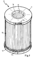
- FIG. 1 shows a filter element 10 in which a filter medium 13 is arranged between a first end disk 11 and a second end disk 12.
- the filter medium 13 consists of zigzag folded paper and is melted at its end faces at the melting zones 17a, 17b in the end plates 11, 12.
- the melting zone 17a is shown schematically in a partial section.
- Both end plates 11, 12 are formed of thermoplastic material.
- a cylindrical opening 15 is visible in the center of the first end plate 11, a cylindrical opening 15 is visible.
- a rubber ring 14 is arranged at the lower end plate 12, a web 18 is provided at a radial distance to the filter medium 13 in one piece with the lower Endset12.
- FIG. 2 shows the filter element 10 according to FIG. 1 in full section.
- the Figure 1 corresponding components are provided with the same reference numerals.
- the filter medium 13 is melted into the end disks 11, 12 at the frontal melting zones 17a, 17b.
- the melt zone 17a encloses an annular region of the thermoplastic end plate 11 and a T-shaped rubber ring 14a arranged on the inner, radial circumference.
- the T-shaped rubber ring 14 a is vulcanized into a T-shaped contour 20 of the first end plate 11 and establishes a tight and releasable connection to a connecting element 16.
- a serrated rubber ring 14b is vulcanized into a serrated contour 19 of the second end plate 12.
- the connection between the second end plate 12 and the serrated rubber ring 14b results in a larger connection surface and a better positive connection of the materials.
- the lower end disk 12 has a web 18, which encloses the filter medium 13 in a ring-shaped manner at a radial distance. Up to the height of the web 18, a collecting space 21 is formed for collecting coarse dirt particles.
- a filter element 110 is shown in fragmentary form.
- a filter medium 113 is sealingly closed at its upper end face with a nitrile rubber end disk 111.
- the filter medium 113 is embedded in a melting zone 117 of the end plate 111.
- the nitrile rubber end disk 111 has a rubber ring 114 towards a cylindrical opening 115.
- a fleece ring 121 is embedded at the upper end side, which extends from the cylindrical opening 115 via an annular region of the rubber ring 114 and the end plate 111.
- the non-woven ring 121 has the property of not affecting the radial elasticity of the end plate and to effectively prevent tearing of the elastic material.
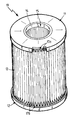
- FIG. 4 shows a filter element 110 according to FIG. 3 in a perspective view. Components which correspond to the figure 3, are provided with the same reference numerals.
- the filter medium 113 is sealingly closed off by an upper nitrile rubber end disk 111 and a lower nitrile rubber end disk 112.
- the fleece ring 121 terminates radially flush with the rubber ring 114 relative to the cylindrical opening 115.
Landscapes
- Chemical & Material Sciences (AREA)
- Chemical Kinetics & Catalysis (AREA)
- Filtering Materials (AREA)
- Filtration Of Liquid (AREA)
- Filtering Of Dispersed Particles In Gases (AREA)
Abstract
Description
- Die Erfindung betrifft eine Endscheibe für ein Filtermedium gemäß dem Oberbegriff des Patentanspruches 1. Außerdem betrifft die Erfindung zwei Herstellungsverfahren nach den Ansprüchen 7 und 8 sowie ein Filterelement nach Anspruch 9.
- Endscheiben für Filtermedien haben die Aufgabe, die fluiddurchlässigen Filtermedien auf den Stirnseiten dichtend zu verschließen. Zusätzlich schaffen die Endscheiben Anschlussöffnungen, welche eine Rohseite von einer Reinseite trennen. Durch diese Anschlussöffnungen müssen die Endscheiben mit einem Anschlusselement lösbar und dichtend verbindbar sein. Eine derartige Endscheibe ist beispielsweise aus der
DE 198 13 319 bekannt. Dabei ist an einer thermoplastischen Endscheibe eines Filters an einer Stirnseite ein Kautschukring angespritzt. Dieser soll eine einfache Montage des Filters gewährleisten und eine betriebssichere Abdichtung erreichen. Nachteilig dabei ist, dass zur Aufnahme des Kautschukringes an der Endscheibe Aufnahmekonturen angeordnet worden sind, welche den Filter in axialer Länge überragen. Das eingespritzte Kautschukelement überragt wiederum die Aufnahmekonturen, wodurch ein erheblicher Einbauraum für die Endscheibe erforderlich ist. - Aufgabe der Erfindung ist es, eine Endscheibe für ein Filterelement zu schaffen, welche eine zuverlässige Abdichtung und eine einfache Montage erlaubt. Weiterhin soll die Endscheibe einfach und wirtschaftlich vorteilhaft herstellbar sein.
- Diese Aufgabe wird durch die Merkmale der unabhängigen Ansprüche gelöst.
- Die erfindungsgemäße Endscheibe eignet sich vorzugsweise zur Abdichtung von Filtermedien, die um eine Zylinderachse gefaltet sind. Als Filtermedien kommen dazu vorzugsweise Filterpapiere oder Vliesstoffe zum Einsatz. Die Endscheibe bildet wenigstens ein stirnseitiges Ende des Filtermediums und ist mit diesem fest und dichtend verbunden. Um eine dichte und leicht lösbare Verbindung zu einem Anschlusselement herzustellen, ist im Zentrum der Endscheibe eine zylindrische Öffnung angeordnet. Das Anschlusselement kann beispielsweise ein zylindrischer Stutzen oder ein Anschlusselement sein, welches die zylindrische Öffnung durchdringt. Um eine zuverlässige Dichtheit zu gewährleisten, ist an der radialen Innenseite der Endscheibe ein radialelastischer Kautschukring mit angeordnet. Dieser ist mit der Endscheibe beispielsweise durch Vulkanisation vernetzt oder durch mechanische Retention verkrallt bzw. durch Hinterschnitt verbunden. Der Kautschukring ist somit ein Teil der Endscheibe und schließt am stirnseitigen Ende des Filterelementes bündig ab oder ist von der Stirnseite in die axiale Innenseite des Filterelementes zurückgesetzt.
- Die Endscheibe kann in vorteilhafter Weise aus Materialien mit unterschiedlicher Elastizität hergestellt werden. Zweckmäßigerweise wird ein mechanisch starres Material verwendet, das einen verwindungssteifen Träger bildet. Als zweites Material weist der Kautschukring die zur Abdichtung notwendige Elastizität auf. Die beiden Materialien können in radialer Richtung nebeneinander angeordnet sein und bilden eine im Wesentlichen plane Ebene. Dadurch kann die wirksame Filterfläche bei gleichem Einbauraum vergrößert oder der Einbauraum entsprechend reduziert werden.
- In einer vorteilhaften Ausgestaltung der Erfindung ist die Endscheibe aus einem Thermoplast gebildet. Der Kautschukring ist an der radialen Innenseite in die Endscheibe einvulkanisiert. Die thermoplastische Endscheibe kann vorzugsweise im Spritzgießverfahren hergestellt werden. Dadurch können an der Endscheibe zusätzliche Funktionskonturen wie beispielsweise Rippen, Stege, Nuten oder Aussparrungen angeordnet sein. Diese können beispielsweise zur Versteifung der Endscheibe oder zur Aufnahme von Führungselementen z. B. zur Zentrierung dienen.
- Vorteilhaft ist es dadurch möglich, ohne wesentlichen wirtschaftlichen Mehraufwand in der Endscheibe weitere Funktionen zu integrieren. Gleichzeitig kann eine verwindungssteife Endscheibe bei minimalem Materialaufwand und Gewicht hergestellt werden.
- Gemäß einer weiteren vorteilhaften Ausgestaltung sind an der Endscheibe ringförmige Profilkonturen zur Aufnahme des Kautschukringes angeordnet. Der Kautschukring kann fertigungstechnisch mit der thermoplastischen Endscheibe durch mechanische Retention verbunden sein. Dies entspricht einer formschlüssigen Verbindung, die durch Verkrallung mit Hinterschnitt der Oberflächen entsteht.
- Durch die Profilkonturen wird die Verbindungsfläche insgesamt vergrößert. Die Profilkonturen können beispielsweise durch Zacken, Rillen oder Nuten gebildet werden, welche vorzugsweise radial umlaufend angeformt sind. Durch die Profilkonturen wird die Festigkeit und Dichtheit des Kautschukringes gegenüber der Endscheibe vorteilhaft erhöht.
- Gemäß einer weiteren Ausgestaltung der Erfindung besteht die Endscheibe aus einem Nitrilkautschuk. Der Nitrilkautschuk ist dabei im stirnseitigen Bereich in das Filtermedium einvulkanisiert. Nach der Aushärtung weist der Nitrilkautschuk eine ausreichende Steifigkeit auf. Dies erlaubt auch den Einsatz bei hohen Temperaturen von bis 170°C, wie sie beispielsweise im Motorenöl einer Brennkraftmaschine auftreten.
- Eine weitere Optimierung kann dadurch erreicht werden, dass dem Nitrilkautschuk Phenolharz oder Epoxidharz beigemengt ist. Zur Abstimmung der Steifigkeit, der chemischen Beständigkeit und der optimalen Haftfähigkeit können auch Phenolharz und Epoxidharz beigemengt werden.
- Die Beimengung von Epoxidharz zu Nitrilkautschuk bewirkt eine wesentlich bessere Verbindung gegenüber dem Kautschukring und dem Filtermedium. Weiterhin erhöht sich die Beständigkeit gegenüber Kraftstoffen, wie beispielsweise Diesel, insbesondere auch Raps-Methylester (RME) oder auch Benzin. Dabei sind Elastizität und Feinheit der Porenstruktur auch bei längerem Kontakt mit den genannten Kraftstoffen gewährleistet. Somit wird der Einsatz bei der Filtration von Kraftstoffen möglich.
- In einer weiteren vorteilhaften Kombination der verwendeten Materialien ist der Kautschukring aus Acrylat-Ethylen-Kautschuk (AEM) oder aus Fluor-Kautschuk (FKM) gebildet. Diese Stoffe weisen eine erhöhte Beständigkeit gegenüber den zu filternden Fluiden auf. Alternativ steht noch Fluorsilicon-Kautschuk (FVMQ) zur Verfügung. Eine erhöhte Beständigkeit gegenüber Kraftstoffen wird insbesondere bei der Verwendung von FVMQ erreicht, wobei der Werkstoff FKM auch eine hohe Beständigkeit gegenüber Raps-Methylester aufweist.
- Gemäß einer weiteren Ausgestaltung ist ein Vliesring in die Endscheibe eingebettet. Dieser ist vorzugsweise direkt an der stirnseitigen Außenseite angeordnet und schließt bündig mit der Stirnseite ab. Der Vliesring ist konzentrisch in unmittelbarer Nähe der radialen Innenseite des Kautschukringes angeordnet. Der Vliesring stabilisiert die Endscheibe stabilisiert und verhindert eine Überdehnung. Dies wird ohne zusätzlichen Bauraum und ohne eine Beeinträchtigung der Elastizität im Dichtbereich gegenüber dem Anschlusselement erreicht.
- Die Erfindung betrifft auch ein Verfahren zur Herstellung einer thermoplastischen Endscheibe. Dazu wird ein thermoplastischer Rohling in eine Aufnahme eingelegt. Anschließend wird ein unvulkanisierter Kautschukring in den thermoplastischen Rohling eingelegt. Der Kautschukring wird durch Konturen, welche in der Aufnahme oder am Rohling vorhanden sind, zentriert. Anschließend werden Rohling und Kautschukring durch eine Wärmequelle erhitzt, wodurch die Oberfläche des Rohlings angeschmolzen und in einen plastischen Zustand versetzt wird. Gleichzeitig wird ein Vulkanisationsprozess des Kautschukringes aktiviert und dieser beginnt aufzuquellen. Jetzt wird ein Filtermedium in die plastische Oberfläche von Rohling und Kautschukring eingedrückt und fixiert. Dadurch verbinden sich der Rohling, der Kautschukring und das Filtermedium. Nach dem Aushärten kann das entstandene Filterelement aus der Aufnahme entfernt werden.
- In einem weiteren erfindungsgemäßen Verfahren wird eine Nitrilkautschuk-Endscheibe hergestellt. Dabei wird zuerst ein Vliesring in eine Form, welche zur Aufnahme aller notwendigen Komponenten gestaltet ist, eingelegt. Anschließend werden ein aus Nitrilkautschuk bestehender Rohling und ein unvulkanisierter Kautschukring in die Form eingelegt. Durch Einwirkung von thermischer Energie wird ein Vulkanisationsprozess des Rohlings und des Kautschukringes eingeleitet, wodurch diese aufquellen. Ein Filtermedium wird mittels einer Druckkraft in die aufgequollene, plastische Oberfläche eingedrückt. Der Prozess erlaubt es auch, zwei gegenüberliegende Endscheiben gleichzeitig mit einem Filtermedium zu vulkanisieren. Nach einer Aushärtezeit kann das entstandene Filterelement aus der Aufnahme entnommen werden.
- Die Erfindung befasst sich weiterhin mit einem Filterelement, welches aus einem Filtermedium und wenigstens einer Endscheibe gemäß Anspruch 1 besteht. Dabei ist das Filtermedium vorzugsweise aus einem zickzackförmigen Papier oder Vlies gebildet und um eine im Wesentlichen zylindrische Achse gefaltet. Auf wenigstens einer Stirnseite ist das Filtermedium in eine Endscheibe gemäß Anspruch 1 einplastifiziert. Diese weist eine zentrische Öffnung auf, welche in eingebautem Zustand eine dichte und lösbare Verbindung mit einem Anschlusselement herstellt. Zum Anschlusselement hin weist die Endscheibe einen elastischen Kautschukring auf, welche von einem weniger elastischen Rohling umgeben ist.
- Durch den radial mehrschichtigen Aufbau der Endscheibe kann die zur Abdichtung notwendige Elastizität vom radial innenliegenden Kautschukring erfüllt werden. Durch die Elastizität der Materialien können die Vorspannkräfte reduziert werden, wodurch sich die Montage- und Demontagekräfte minimieren lassen. Deshalb eignet sich das Filterelement in vorteilhafter Weise als Wechselelement zur Öl- und Kraftstofffiltration.
- Diese und weitere Merkmale von bevorzugten Weiterbildungen der Erfindung gehen außer aus den Ansprüchen auch aus der Beschreibung und der Zeichnung hervor, wobei die einzelnen Merkmale jeweils für sich allein oder zu mehreren in Form von Unterkombinationen bei der Ausführungsform der Erfindung und auf anderen Gebieten verwirklicht sein und vorteilhafte sowie für sich schutzfähige Ausführungen darstellen können, für die hier Schutz beansprucht wird.
- Ausführungsbeispiele der Erfindung werden anhand von schematischen Darstellungen beschrieben.
- Hierbei zeigen
- Figur 1 ein Filterelement mit thermoplastischen Endscheiben in perspektivischer Darstellung,
- Figur 2 ein Filterelement gemäß Figur 1 im Vollschnitt, und
- Figur 3 einen Ausschnitt aus einem Filterelement mit Nitrilkautschukendscheibe im Vollschnitt. Ausführungsform(en) der Erfindung
- Figur 1 zeigt ein Filterelement 10, in welchem zwischen einer ersten Endscheibe 11 und einer zweiten Endscheibe 12 ein Filtermedium 13 angeordnet ist. Das Filtermedium 13 besteht aus zickzackförmig gefaltetem Papier und ist an seinen Stirnseiten an den Schmelzzonen17a, 17b in die Endscheiben 11, 12 eingeschmolzen. Die Schmelzzone 17a ist in einem Teilausschnitt schematisch dargestellt. Beide Endscheiben 11, 12 sind aus thermoplastischem Material gebildet. Im Zentrum der ersten Endscheibe 11 ist eine zylindrische Öffnung 15 sichtbar. Um an der radialen Innenseite der ersten Endscheibe 11 einen elastischen Bereich zu schaffen, ist ein Kautschukring 14 angeordnet. An der unteren Endscheibe 12 ist ein Steg 18 mit radialem Abstand zu Filtermedium 13 einstückig mit der unteren Endscheibe12 vorgesehen.
- Figur 2 zeigt das Filterelement 10 gemäß Figur 1 im Vollschnitt. Der Figur 1 entsprechende Bauteile sind mit denselben Bezugszeichen versehen. Das Filtermedium 13 ist an den stirnseitigen Schmelzzonen 17a, 17b in die Endscheiben 11, 12 eingeschmolzen. Die Schmelzzone 17a umschließt einen ringförmigen Bereich der thermoplastischen Endscheibe 11 und einen am inneren, radialen Umfang angeordneten T-förmigen Kautschukring 14a. Der T-förmige Kautschukring 14 a ist in eine T-Kontur 20 der ersten Endscheibe 11 einvulkanisiert und stellt eine dichte und lösbare Verbindung zu einem Anschlusselement 16 her. An der unten angeordneten zweiten Endscheibe 12 ist ein gezackter Kautschukring 14b in eine Zackenkontur 19 der zweiten Endscheibe 12 einvulkanisiert. Durch die Verbindung zwischen der zweiten Endscheibe 12 und dem gezackten Kautschukring 14b entsteht eine größere Verbindungsfläche und eine bessere formschlüssige Verbindung der Materialien. Als zusätzliche Funktionskontur weist die untere Endscheibe 12 einen Steg 18 auf, welcher das Filtermedium 13 in einem radialen Abstand ringförmig umschließt. Bis zur Höhe des Steges 18 bildet sich ein Sammelraum 21 zum Auffangen von groben Schmutzpartikeln.
- In Figur 3 ist ein Filterelement 110 ausschnittsweise dargestellt. Ein Filtermedium 113 ist an seiner oberen Stirnseite mit einer Nitrilkautschukendscheibe 111 dichtend verschlossen. Dazu ist das Filtermedium 113 in eine Schmelzzone 117 der Endscheibe 111 eingebettet. An der radialen Innenseite weist die Nitrilkautschukendscheibe 111 zu einer zylindrischen Öffnung 115 hin einen Kautschukring 114 auf. In der Nitrilkautschukendscheibe ist an der oberen Stirnseite ein Vliesring 121 eingebettet, welcher sich von der zylindrischen Öffnung 115 über einen Ringbereich des Kautschukringes 114 und der Endscheibe 111 erstreckt. Der Vliesring 121 hat die Eigenschaft, die radiale Elastizität der Endscheibe nicht zu beeinflussen und ein Einreißen des elastischen Materials wirksam zu verhindern.
- Figur 4 zeigt ein Filterelement 110 gemäß Figur 3 in perspektivischer Darstellung. Bauteile, die der Figur 3 entsprechen, sind mit den gleichen Bezugszeichen versehen. Das Filtermedium 113 wird stirnseitig von einer oberen Nitrilkautschukendscheibe 111 und einer unteren NitrilkautschukEndscheibe 112 dichtend abgeschlossen. Der Vliesring 121 schließt radial bündig mit dem Kautschukring 114 gegenüber der zylindrischen Öffnung 115 ab.
Claims (9)
- Endscheibe für ein vorzugsweise ringförmig um eine Zylinderachse gefaltetes Filtermedium, wobei diese über einen Bereich in eine Stirnseite des Filtermediums einplastifiziert ist und an ihrer radialen Innenseite einen Kautschukring aufweist, dadurch gekennzeichnet, dass der anvulkanisierte Kautschukring bündig zu der äußeren Stirnseite oder unter der äußeren Stirnseite der Endscheibe angeordnet ist und eine dichte und lösbare Verbindung zu einem im Zentrum angeordneten Anschlusselement herstellt.
- Endscheibe nach Anspruch 1, dadurch gekennzeichnet, dass diese aus einem Thermoplast oder einem Nitrilkautschuk besteht.
- Endscheibe nach einem der vorhergehenden Ansprüche, dadurch gekennzeichnet, dass zur Anordnung des Kautschukringes an der radialen Innenseite ringförmige Profilkonturen angeordnet sind.
- Endscheibe nach Anspruch 2, dadurch gekennzeichnet, dass dem Nitrilkautschuk Phenolharz und/oder Epoxidharz beigemengt ist.
- Endscheibe nach Anspruch 2, dadurch gekennzeichnet, dass ein Vliesring eingebettet ist.
- Endscheibe nach einem der vorhergehenden Ansprüche, dadurch gekennzeichnet, dass der Kautschukring aus Acrylat-Ethylen-Kautschuk oder Fluor-kautschuk gebildet ist.
- Verfahren zur Herstellung einer Endscheibe gemäß Anspruch 2, gekennzeichnet durch folgende Schritte:- Einlegen eines thermoplastischen Rohlings in eine Aufnahme,- Einlegen eines Kautschukringes in den thermoplastischen Rohling,- Anschmelzen des Rohlings und Aktivierung der Vulkanisation,- Einbetten eines Filtermediums in die plastische Masse,- Aushärten der Schmelze.
- Verfahren zur Herstellung einer Endscheibe gemäß Anspruch 2, gekennzeichnet durch folgende Schritte:- Einbringen eines Vliesringes in eine Aufnahme,- Einbringen eines Kautschukringes und eines Rohlinges aus Nitrilkautschuk in die Aufnahme,- Einbringen eines Filtermediums auf den in der Aufnahme liegenden Rohling und den Kautschukring,- Aktivierung der Vulkanisation durch Zuführung thermischer Energie,- Aushärten der elastischen Masse.
- Filterelement aufweisend wenigstens eine Endscheibe nach Anspruch 1.
Priority Applications (1)
| Application Number | Priority Date | Filing Date | Title |
|---|---|---|---|
| PL06110734T PL1702663T3 (pl) | 2005-03-08 | 2006-03-06 | Płytka zakończeniowa dla medium filtrującego |
Applications Claiming Priority (1)
| Application Number | Priority Date | Filing Date | Title |
|---|---|---|---|
| DE102005010437A DE102005010437A1 (de) | 2005-03-08 | 2005-03-08 | Endscheibe für ein Filtermedium |
Publications (2)
| Publication Number | Publication Date |
|---|---|
| EP1702663A1 true EP1702663A1 (de) | 2006-09-20 |
| EP1702663B1 EP1702663B1 (de) | 2009-01-21 |
Family
ID=36515669
Family Applications (1)
| Application Number | Title | Priority Date | Filing Date |
|---|---|---|---|
| EP06110734A Expired - Lifetime EP1702663B1 (de) | 2005-03-08 | 2006-03-06 | Verfahren zur Herstellung einer Endscheibe für ein Filtermedium |
Country Status (5)
| Country | Link |
|---|---|
| EP (1) | EP1702663B1 (de) |
| AT (1) | ATE421373T1 (de) |
| DE (2) | DE102005010437A1 (de) |
| ES (1) | ES2317421T3 (de) |
| PL (1) | PL1702663T3 (de) |
Cited By (3)
| Publication number | Priority date | Publication date | Assignee | Title |
|---|---|---|---|---|
| WO2009080706A1 (de) * | 2007-12-21 | 2009-07-02 | Mann+Hummel Gmbh | Filtereinrichtung, insbesondere flüssigkeitsfilter |
| DE102009057500A1 (de) * | 2009-12-10 | 2011-06-16 | Mann+Hummel Gmbh | Filtereinsatz |
| DE102015008873A1 (de) | 2014-08-05 | 2016-02-25 | Mann+Hummel Gmbh | Filterelement mit einem hohlzylindrischen Filtermediumkörper und Filtereinrichtung |
Families Citing this family (2)
| Publication number | Priority date | Publication date | Assignee | Title |
|---|---|---|---|---|
| DE102016008502A1 (de) | 2016-07-15 | 2017-06-01 | Mann + Hummel Gmbh | Filterelement und Verfahren zur Herstellung desselben |
| DE102024108240A1 (de) * | 2024-03-22 | 2025-09-25 | Jvk Filtration Systems Gmbh | Fugenfreie Abdichtung von Filterelementen |
Citations (6)
| Publication number | Priority date | Publication date | Assignee | Title |
|---|---|---|---|---|
| DE4441608A1 (de) * | 1994-11-23 | 1996-06-05 | Mann & Hummel Filter | Filteranordnung |
| DE19813319A1 (de) | 1998-03-26 | 1999-09-30 | Knecht Filterwerke Gmbh | Ringförmige Kunststoff-Endscheibe aus Polyamid für ein Ringfilter |
| EP1180387A1 (de) * | 2000-08-17 | 2002-02-20 | MAHLE Filtersysteme GmbH | Ringförmiges Filterelement mit einer Vlies-Endscheibe sowie Verfahren zu dessen Herstellung |
| US6585894B1 (en) * | 1998-03-26 | 2003-07-01 | Mahle Filtersysteme Gmbh | Ring-shaped filter element including an annular end plate and a foamed elastic sealing ring |
| DE10235902A1 (de) * | 2002-08-06 | 2004-02-19 | Mann + Hummel Gmbh | Flüssigkeitsfilter, insbesondere Ölfilter für Kraftfahrzeuge |
| EP1520611A1 (de) * | 2003-10-01 | 2005-04-06 | Mann+Hummel Gmbh | Ringfilterelement |
-
2005
- 2005-03-08 DE DE102005010437A patent/DE102005010437A1/de not_active Ceased
-
2006
- 2006-03-06 PL PL06110734T patent/PL1702663T3/pl unknown
- 2006-03-06 EP EP06110734A patent/EP1702663B1/de not_active Expired - Lifetime
- 2006-03-06 ES ES06110734T patent/ES2317421T3/es not_active Expired - Lifetime
- 2006-03-06 DE DE502006002685T patent/DE502006002685D1/de not_active Expired - Lifetime
- 2006-03-06 AT AT06110734T patent/ATE421373T1/de not_active IP Right Cessation
Patent Citations (6)
| Publication number | Priority date | Publication date | Assignee | Title |
|---|---|---|---|---|
| DE4441608A1 (de) * | 1994-11-23 | 1996-06-05 | Mann & Hummel Filter | Filteranordnung |
| DE19813319A1 (de) | 1998-03-26 | 1999-09-30 | Knecht Filterwerke Gmbh | Ringförmige Kunststoff-Endscheibe aus Polyamid für ein Ringfilter |
| US6585894B1 (en) * | 1998-03-26 | 2003-07-01 | Mahle Filtersysteme Gmbh | Ring-shaped filter element including an annular end plate and a foamed elastic sealing ring |
| EP1180387A1 (de) * | 2000-08-17 | 2002-02-20 | MAHLE Filtersysteme GmbH | Ringförmiges Filterelement mit einer Vlies-Endscheibe sowie Verfahren zu dessen Herstellung |
| DE10235902A1 (de) * | 2002-08-06 | 2004-02-19 | Mann + Hummel Gmbh | Flüssigkeitsfilter, insbesondere Ölfilter für Kraftfahrzeuge |
| EP1520611A1 (de) * | 2003-10-01 | 2005-04-06 | Mann+Hummel Gmbh | Ringfilterelement |
Cited By (6)
| Publication number | Priority date | Publication date | Assignee | Title |
|---|---|---|---|---|
| WO2009080706A1 (de) * | 2007-12-21 | 2009-07-02 | Mann+Hummel Gmbh | Filtereinrichtung, insbesondere flüssigkeitsfilter |
| DE102009057500A1 (de) * | 2009-12-10 | 2011-06-16 | Mann+Hummel Gmbh | Filtereinsatz |
| DE202009018835U1 (de) | 2009-12-10 | 2013-11-14 | Mann + Hummel Gmbh | Filtereinsatz |
| DE102009057500B4 (de) * | 2009-12-10 | 2014-01-16 | Mann + Hummel Gmbh | Filtereinsatz |
| DE102015008873A1 (de) | 2014-08-05 | 2016-02-25 | Mann+Hummel Gmbh | Filterelement mit einem hohlzylindrischen Filtermediumkörper und Filtereinrichtung |
| US10413849B2 (en) | 2014-08-05 | 2019-09-17 | Mann+Hummel Gmbh | Filter element comprising hollow cylindrical filter medium body and filter device |
Also Published As
| Publication number | Publication date |
|---|---|
| EP1702663B1 (de) | 2009-01-21 |
| ATE421373T1 (de) | 2009-02-15 |
| DE102005010437A1 (de) | 2006-09-21 |
| PL1702663T3 (pl) | 2009-06-30 |
| DE502006002685D1 (de) | 2009-03-12 |
| ES2317421T3 (es) | 2009-04-16 |
Similar Documents
| Publication | Publication Date | Title |
|---|---|---|
| EP2813275B1 (de) | Verwendung eines filterelementes in einem filtersystem | |
| EP2471587B1 (de) | Kraftstofffilter | |
| EP2296776B1 (de) | Adapter zur befestigung eines filterelementes | |
| CH615101A5 (de) | ||
| DE202007018076U1 (de) | Filtereinrichtung, insbesondere Flüssigkeitsfilter | |
| WO2016030419A1 (de) | Filter, der an einen anschlussflansch anbaubar ist, und filtereinsatz | |
| WO1998008589A1 (de) | Filterpatrone | |
| WO2000056423A1 (de) | Filter mit topfförmigem gehäuse und rundfilterpatrone | |
| EP1440721B1 (de) | Selbstentlüftendes Filterelement für eine Kraftstofffilteranordnung | |
| EP0667177B1 (de) | Flüssigkeitsfilter | |
| DE112016007227T5 (de) | Luftfilter | |
| EP1736227B1 (de) | Filterdichtsystem | |
| EP1071501A1 (de) | Endscheibe für ein ringförmiges, radial durchströmbares filter | |
| DE102014011394B4 (de) | Ölfilterelement und Ölfilter | |
| WO2000025892A1 (de) | Filterpatronenanordnung | |
| EP1702663B1 (de) | Verfahren zur Herstellung einer Endscheibe für ein Filtermedium | |
| EP1695751B1 (de) | Kunststoffendscheibe | |
| EP1728541A1 (de) | Filterelement für einen Flüssigkeitsfilter | |
| DE29922324U1 (de) | Flüssigkeitsfilter | |
| DE19813319A1 (de) | Ringförmige Kunststoff-Endscheibe aus Polyamid für ein Ringfilter | |
| DE10124612B4 (de) | Rundfilterpatrone und Herstellungsverfahren für eine solche Rundfilterpatrone | |
| EP1388360B1 (de) | Ringfiltereinsatz für ein Fluidfilter | |
| WO2002064234A2 (de) | Zylindrische filterpatrone mit stützrohr | |
| DE102014009027A1 (de) | Filterelement, insbesondere Kraftstofffilterelement und Verfahren zum Herstellen desselben | |
| DE102014005348B4 (de) | Filterelement eines Filters und Filter |
Legal Events
| Date | Code | Title | Description |
|---|---|---|---|
| PUAI | Public reference made under article 153(3) epc to a published international application that has entered the european phase |
Free format text: ORIGINAL CODE: 0009012 |
|
| AK | Designated contracting states |
Kind code of ref document: A1 Designated state(s): AT BE BG CH CY CZ DE DK EE ES FI FR GB GR HU IE IS IT LI LT LU LV MC NL PL PT RO SE SI SK TR |
|
| AX | Request for extension of the european patent |
Extension state: AL BA HR MK YU |
|
| 17P | Request for examination filed |
Effective date: 20070214 |
|
| 17Q | First examination report despatched |
Effective date: 20070316 |
|
| AKX | Designation fees paid |
Designated state(s): AT BE BG CH CY CZ DE DK EE ES FI FR GB GR HU IE IS IT LI LT LU LV MC NL PL PT RO SE SI SK TR |
|
| RTI1 | Title (correction) |
Free format text: END CAP FOR A FILTER MEDIA |
|
| GRAP | Despatch of communication of intention to grant a patent |
Free format text: ORIGINAL CODE: EPIDOSNIGR1 |
|
| RTI1 | Title (correction) |
Free format text: METHOD FOR MANUFACTURING AN END CAP FOR A FILTER MEDIA |
|
| GRAS | Grant fee paid |
Free format text: ORIGINAL CODE: EPIDOSNIGR3 |
|
| GRAA | (expected) grant |
Free format text: ORIGINAL CODE: 0009210 |
|
| AK | Designated contracting states |
Kind code of ref document: B1 Designated state(s): AT BE BG CH CY CZ DE DK EE ES FI FR GB GR HU IE IS IT LI LT LU LV MC NL PL PT RO SE SI SK TR |
|
| REG | Reference to a national code |
Ref country code: GB Ref legal event code: FG4D Free format text: NOT ENGLISH |
|
| REG | Reference to a national code |
Ref country code: CH Ref legal event code: EP |
|
| REG | Reference to a national code |
Ref country code: IE Ref legal event code: FG4D Free format text: LANGUAGE OF EP DOCUMENT: GERMAN |
|
| REF | Corresponds to: |
Ref document number: 502006002685 Country of ref document: DE Date of ref document: 20090312 Kind code of ref document: P |
|
| REG | Reference to a national code |
Ref country code: DE Ref legal event code: R096 Ref document number: 502006002685 Country of ref document: DE Effective date: 20090312 |
|
| REG | Reference to a national code |
Ref country code: ES Ref legal event code: FG2A Ref document number: 2317421 Country of ref document: ES Kind code of ref document: T3 |
|
| PG25 | Lapsed in a contracting state [announced via postgrant information from national office to epo] |
Ref country code: NL Free format text: LAPSE BECAUSE OF FAILURE TO SUBMIT A TRANSLATION OF THE DESCRIPTION OR TO PAY THE FEE WITHIN THE PRESCRIBED TIME-LIMIT Effective date: 20090121 |
|
| REG | Reference to a national code |
Ref country code: PL Ref legal event code: T3 |
|
| NLV1 | Nl: lapsed or annulled due to failure to fulfill the requirements of art. 29p and 29m of the patents act | ||
| PG25 | Lapsed in a contracting state [announced via postgrant information from national office to epo] |
Ref country code: LT Free format text: LAPSE BECAUSE OF FAILURE TO SUBMIT A TRANSLATION OF THE DESCRIPTION OR TO PAY THE FEE WITHIN THE PRESCRIBED TIME-LIMIT Effective date: 20090121 Ref country code: SI Free format text: LAPSE BECAUSE OF FAILURE TO SUBMIT A TRANSLATION OF THE DESCRIPTION OR TO PAY THE FEE WITHIN THE PRESCRIBED TIME-LIMIT Effective date: 20090121 Ref country code: FI Free format text: LAPSE BECAUSE OF FAILURE TO SUBMIT A TRANSLATION OF THE DESCRIPTION OR TO PAY THE FEE WITHIN THE PRESCRIBED TIME-LIMIT Effective date: 20090121 |
|
| REG | Reference to a national code |
Ref country code: IE Ref legal event code: FD4D |
|
| PG25 | Lapsed in a contracting state [announced via postgrant information from national office to epo] |
Ref country code: PT Free format text: LAPSE BECAUSE OF FAILURE TO SUBMIT A TRANSLATION OF THE DESCRIPTION OR TO PAY THE FEE WITHIN THE PRESCRIBED TIME-LIMIT Effective date: 20090622 Ref country code: SE Free format text: LAPSE BECAUSE OF FAILURE TO SUBMIT A TRANSLATION OF THE DESCRIPTION OR TO PAY THE FEE WITHIN THE PRESCRIBED TIME-LIMIT Effective date: 20090421 Ref country code: LV Free format text: LAPSE BECAUSE OF FAILURE TO SUBMIT A TRANSLATION OF THE DESCRIPTION OR TO PAY THE FEE WITHIN THE PRESCRIBED TIME-LIMIT Effective date: 20090121 Ref country code: IS Free format text: LAPSE BECAUSE OF FAILURE TO SUBMIT A TRANSLATION OF THE DESCRIPTION OR TO PAY THE FEE WITHIN THE PRESCRIBED TIME-LIMIT Effective date: 20090521 |
|
| BERE | Be: lapsed |
Owner name: MANN + HUMMEL G.M.B.H. Effective date: 20090331 |
|
| PG25 | Lapsed in a contracting state [announced via postgrant information from national office to epo] |
Ref country code: MC Free format text: LAPSE BECAUSE OF NON-PAYMENT OF DUE FEES Effective date: 20090331 Ref country code: IE Free format text: LAPSE BECAUSE OF FAILURE TO SUBMIT A TRANSLATION OF THE DESCRIPTION OR TO PAY THE FEE WITHIN THE PRESCRIBED TIME-LIMIT Effective date: 20090121 Ref country code: EE Free format text: LAPSE BECAUSE OF FAILURE TO SUBMIT A TRANSLATION OF THE DESCRIPTION OR TO PAY THE FEE WITHIN THE PRESCRIBED TIME-LIMIT Effective date: 20090121 Ref country code: DK Free format text: LAPSE BECAUSE OF FAILURE TO SUBMIT A TRANSLATION OF THE DESCRIPTION OR TO PAY THE FEE WITHIN THE PRESCRIBED TIME-LIMIT Effective date: 20090121 |
|
| PLBE | No opposition filed within time limit |
Free format text: ORIGINAL CODE: 0009261 |
|
| STAA | Information on the status of an ep patent application or granted ep patent |
Free format text: STATUS: NO OPPOSITION FILED WITHIN TIME LIMIT |
|
| PG25 | Lapsed in a contracting state [announced via postgrant information from national office to epo] |
Ref country code: SK Free format text: LAPSE BECAUSE OF FAILURE TO SUBMIT A TRANSLATION OF THE DESCRIPTION OR TO PAY THE FEE WITHIN THE PRESCRIBED TIME-LIMIT Effective date: 20090121 Ref country code: RO Free format text: LAPSE BECAUSE OF FAILURE TO SUBMIT A TRANSLATION OF THE DESCRIPTION OR TO PAY THE FEE WITHIN THE PRESCRIBED TIME-LIMIT Effective date: 20090121 |
|
| 26N | No opposition filed |
Effective date: 20091022 |
|
| PG25 | Lapsed in a contracting state [announced via postgrant information from national office to epo] |
Ref country code: BG Free format text: LAPSE BECAUSE OF FAILURE TO SUBMIT A TRANSLATION OF THE DESCRIPTION OR TO PAY THE FEE WITHIN THE PRESCRIBED TIME-LIMIT Effective date: 20090421 |
|
| REG | Reference to a national code |
Ref country code: DE Ref legal event code: R097 Ref document number: 502006002685 Country of ref document: DE Effective date: 20091022 |
|
| PG25 | Lapsed in a contracting state [announced via postgrant information from national office to epo] |
Ref country code: BE Free format text: LAPSE BECAUSE OF NON-PAYMENT OF DUE FEES Effective date: 20090331 |
|
| PG25 | Lapsed in a contracting state [announced via postgrant information from national office to epo] |
Ref country code: AT Free format text: LAPSE BECAUSE OF NON-PAYMENT OF DUE FEES Effective date: 20090306 |
|
| PG25 | Lapsed in a contracting state [announced via postgrant information from national office to epo] |
Ref country code: GR Free format text: LAPSE BECAUSE OF FAILURE TO SUBMIT A TRANSLATION OF THE DESCRIPTION OR TO PAY THE FEE WITHIN THE PRESCRIBED TIME-LIMIT Effective date: 20090422 |
|
| REG | Reference to a national code |
Ref country code: CH Ref legal event code: PL |
|
| PG25 | Lapsed in a contracting state [announced via postgrant information from national office to epo] |
Ref country code: CH Free format text: LAPSE BECAUSE OF NON-PAYMENT OF DUE FEES Effective date: 20100331 Ref country code: LI Free format text: LAPSE BECAUSE OF NON-PAYMENT OF DUE FEES Effective date: 20100331 |
|
| PG25 | Lapsed in a contracting state [announced via postgrant information from national office to epo] |
Ref country code: LU Free format text: LAPSE BECAUSE OF NON-PAYMENT OF DUE FEES Effective date: 20090306 |
|
| PG25 | Lapsed in a contracting state [announced via postgrant information from national office to epo] |
Ref country code: HU Free format text: LAPSE BECAUSE OF FAILURE TO SUBMIT A TRANSLATION OF THE DESCRIPTION OR TO PAY THE FEE WITHIN THE PRESCRIBED TIME-LIMIT Effective date: 20090722 |
|
| PG25 | Lapsed in a contracting state [announced via postgrant information from national office to epo] |
Ref country code: CY Free format text: LAPSE BECAUSE OF FAILURE TO SUBMIT A TRANSLATION OF THE DESCRIPTION OR TO PAY THE FEE WITHIN THE PRESCRIBED TIME-LIMIT Effective date: 20090121 |
|
| REG | Reference to a national code |
Ref country code: FR Ref legal event code: PLFP Year of fee payment: 11 |
|
| REG | Reference to a national code |
Ref country code: FR Ref legal event code: PLFP Year of fee payment: 12 |
|
| REG | Reference to a national code |
Ref country code: FR Ref legal event code: PLFP Year of fee payment: 13 |
|
| REG | Reference to a national code |
Ref country code: DE Ref legal event code: R081 Ref document number: 502006002685 Country of ref document: DE Owner name: MANN+HUMMEL GMBH, DE Free format text: FORMER OWNER: MANN + HUMMEL GMBH, 71638 LUDWIGSBURG, DE |
|
| P01 | Opt-out of the competence of the unified patent court (upc) registered |
Effective date: 20230601 |
|
| PGFP | Annual fee paid to national office [announced via postgrant information from national office to epo] |
Ref country code: DE Payment date: 20250319 Year of fee payment: 20 |
|
| PGFP | Annual fee paid to national office [announced via postgrant information from national office to epo] |
Ref country code: FR Payment date: 20250325 Year of fee payment: 20 Ref country code: PL Payment date: 20250221 Year of fee payment: 20 Ref country code: CZ Payment date: 20250226 Year of fee payment: 20 |
|
| PGFP | Annual fee paid to national office [announced via postgrant information from national office to epo] |
Ref country code: IT Payment date: 20250325 Year of fee payment: 20 Ref country code: GB Payment date: 20250321 Year of fee payment: 20 |
|
| PGFP | Annual fee paid to national office [announced via postgrant information from national office to epo] |
Ref country code: TR Payment date: 20250225 Year of fee payment: 20 |
|
| PGFP | Annual fee paid to national office [announced via postgrant information from national office to epo] |
Ref country code: ES Payment date: 20250425 Year of fee payment: 20 |
|
| REG | Reference to a national code |
Ref country code: DE Ref legal event code: R071 Ref document number: 502006002685 Country of ref document: DE |
|
| REG | Reference to a national code |
Ref country code: GB Ref legal event code: PE20 Expiry date: 20260305 |
|
| REG | Reference to a national code |
Ref country code: ES Ref legal event code: FD2A Effective date: 20260326 |
|
| PG25 | Lapsed in a contracting state [announced via postgrant information from national office to epo] |
Ref country code: ES Free format text: LAPSE BECAUSE OF EXPIRATION OF PROTECTION Effective date: 20260307 |
|
| PG25 | Lapsed in a contracting state [announced via postgrant information from national office to epo] |
Ref country code: CZ Free format text: LAPSE BECAUSE OF EXPIRATION OF PROTECTION Effective date: 20260306 |