EP1702545A1 - Drive coupler for a food preparation device - Google Patents
Drive coupler for a food preparation device Download PDFInfo
- Publication number
- EP1702545A1 EP1702545A1 EP06250403A EP06250403A EP1702545A1 EP 1702545 A1 EP1702545 A1 EP 1702545A1 EP 06250403 A EP06250403 A EP 06250403A EP 06250403 A EP06250403 A EP 06250403A EP 1702545 A1 EP1702545 A1 EP 1702545A1
- Authority
- EP
- European Patent Office
- Prior art keywords
- drive shaft
- preparation device
- food preparation
- splined
- jar
- Prior art date
- Legal status (The legal status is an assumption and is not a legal conclusion. Google has not performed a legal analysis and makes no representation as to the accuracy of the status listed.)
- Granted
Links
- 235000013305 food Nutrition 0.000 title claims abstract description 34
- 238000002360 preparation method Methods 0.000 title claims abstract description 22
- 230000008878 coupling Effects 0.000 claims description 6
- 238000010168 coupling process Methods 0.000 claims description 6
- 238000005859 coupling reaction Methods 0.000 claims description 6
- 230000007704 transition Effects 0.000 description 7
- NJPPVKZQTLUDBO-UHFFFAOYSA-N novaluron Chemical compound C1=C(Cl)C(OC(F)(F)C(OC(F)(F)F)F)=CC=C1NC(=O)NC(=O)C1=C(F)C=CC=C1F NJPPVKZQTLUDBO-UHFFFAOYSA-N 0.000 description 6
- 230000003466 anti-cipated effect Effects 0.000 description 2
- 230000000295 complement effect Effects 0.000 description 2
- 230000000694 effects Effects 0.000 description 2
- 238000003780 insertion Methods 0.000 description 1
- 230000037431 insertion Effects 0.000 description 1
- 230000003993 interaction Effects 0.000 description 1
- 238000004519 manufacturing process Methods 0.000 description 1
- 235000013372 meat Nutrition 0.000 description 1
- 230000004048 modification Effects 0.000 description 1
- 238000012986 modification Methods 0.000 description 1
- 230000002028 premature Effects 0.000 description 1
- 235000013599 spices Nutrition 0.000 description 1
Images


Classifications
-
- F—MECHANICAL ENGINEERING; LIGHTING; HEATING; WEAPONS; BLASTING
- F16—ENGINEERING ELEMENTS AND UNITS; GENERAL MEASURES FOR PRODUCING AND MAINTAINING EFFECTIVE FUNCTIONING OF MACHINES OR INSTALLATIONS; THERMAL INSULATION IN GENERAL
- F16D—COUPLINGS FOR TRANSMITTING ROTATION; CLUTCHES; BRAKES
- F16D1/00—Couplings for rigidly connecting two coaxial shafts or other movable machine elements
- F16D1/10—Quick-acting couplings in which the parts are connected by simply bringing them together axially
- F16D1/101—Quick-acting couplings in which the parts are connected by simply bringing them together axially without axial retaining means rotating with the coupling
-
- A—HUMAN NECESSITIES
- A47—FURNITURE; DOMESTIC ARTICLES OR APPLIANCES; COFFEE MILLS; SPICE MILLS; SUCTION CLEANERS IN GENERAL
- A47J—KITCHEN EQUIPMENT; COFFEE MILLS; SPICE MILLS; APPARATUS FOR MAKING BEVERAGES
- A47J43/00—Implements for preparing or holding food, not provided for in other groups of this subclass
- A47J43/04—Machines for domestic use not covered elsewhere, e.g. for grinding, mixing, stirring, kneading, emulsifying, whipping or beating foodstuffs, e.g. power-driven
- A47J43/07—Parts or details, e.g. mixing tools, whipping tools
- A47J43/08—Driving mechanisms
- A47J43/085—Driving mechanisms for machines with tools driven from the lower side
-
- F—MECHANICAL ENGINEERING; LIGHTING; HEATING; WEAPONS; BLASTING
- F16—ENGINEERING ELEMENTS AND UNITS; GENERAL MEASURES FOR PRODUCING AND MAINTAINING EFFECTIVE FUNCTIONING OF MACHINES OR INSTALLATIONS; THERMAL INSULATION IN GENERAL
- F16D—COUPLINGS FOR TRANSMITTING ROTATION; CLUTCHES; BRAKES
- F16D3/00—Yielding couplings, i.e. with means permitting movement between the connected parts during the drive
- F16D3/50—Yielding couplings, i.e. with means permitting movement between the connected parts during the drive with the coupling parts connected by one or more intermediate members
- F16D3/64—Yielding couplings, i.e. with means permitting movement between the connected parts during the drive with the coupling parts connected by one or more intermediate members comprising elastic elements arranged between substantially-radial walls of both coupling parts
- F16D3/68—Yielding couplings, i.e. with means permitting movement between the connected parts during the drive with the coupling parts connected by one or more intermediate members comprising elastic elements arranged between substantially-radial walls of both coupling parts the elements being made of rubber or similar material
-
- F—MECHANICAL ENGINEERING; LIGHTING; HEATING; WEAPONS; BLASTING
- F16—ENGINEERING ELEMENTS AND UNITS; GENERAL MEASURES FOR PRODUCING AND MAINTAINING EFFECTIVE FUNCTIONING OF MACHINES OR INSTALLATIONS; THERMAL INSULATION IN GENERAL
- F16D—COUPLINGS FOR TRANSMITTING ROTATION; CLUTCHES; BRAKES
- F16D1/00—Couplings for rigidly connecting two coaxial shafts or other movable machine elements
- F16D1/10—Quick-acting couplings in which the parts are connected by simply bringing them together axially
- F16D2001/102—Quick-acting couplings in which the parts are connected by simply bringing them together axially the torque is transmitted via polygon shaped connections
-
- F—MECHANICAL ENGINEERING; LIGHTING; HEATING; WEAPONS; BLASTING
- F16—ENGINEERING ELEMENTS AND UNITS; GENERAL MEASURES FOR PRODUCING AND MAINTAINING EFFECTIVE FUNCTIONING OF MACHINES OR INSTALLATIONS; THERMAL INSULATION IN GENERAL
- F16D—COUPLINGS FOR TRANSMITTING ROTATION; CLUTCHES; BRAKES
- F16D1/00—Couplings for rigidly connecting two coaxial shafts or other movable machine elements
- F16D1/10—Quick-acting couplings in which the parts are connected by simply bringing them together axially
- F16D2001/103—Quick-acting couplings in which the parts are connected by simply bringing them together axially the torque is transmitted via splined connections
Definitions
- the invention relates generally to motor-driven food preparation devices, and more specifically to a coupling connecting a blender motor to a blender blade assembly which can accommodate misalignment of a blender jar with a blender base.
- Blenders are a common motor-driven appliance in home, commercial, and institutional kitchens.
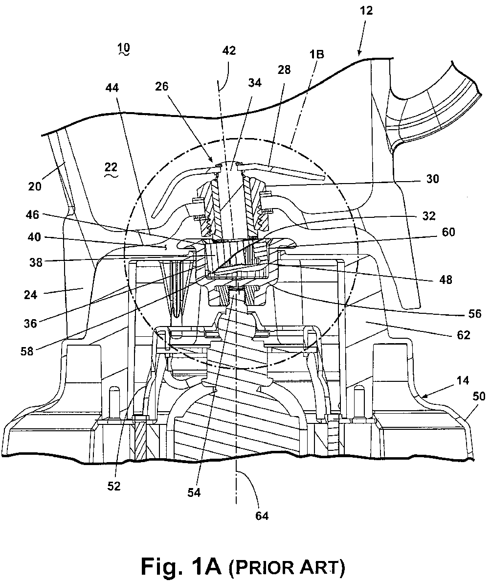
- Figure 1A illustrates in a sectional view a conventional prior art blender assembly 10 comprising a jar 12 and a motorized base 14.
- the jar 12 comprises a perimeter wall 20 and a bottom wall 44 which together define a chamber 22 adapted to hold a food item (not shown).
- the perimeter wall 20 transitions to a downwardly-extending skirt 24 which defines with the bottom wall 44 a skirt recess 40.
- a rotating blade assembly 26 for processing food items in the chamber 22 is mounted to the jar 12.
- the blade assembly 26 comprises a bushing assembly 30 mounted within an opening in the bottom wall 44 of the jar 12 and a drive shaft 34 rotatably mounted to the bushing assembly 30 and defines an axis of rotation 42.
- a blade 28 is mounted to one end of the drive shaft 34 and a male coupler 32 is mounted to the other end of the drive shaft 34.
- the motorized base 14 comprises a base housing 50 enclosing a drive motor 52.
- the armature of the drive motor 52 terminates in an output shaft 54 which mounts a female coupler 56.
- the output shaft 54 defines a second axis of rotation 64.
- the base housing 50 transitions upwardly to ajar pedestal 62 adapted for cooperative registry with the skirt recess 40 when the jar 12 is seated on the base 14.
- the male coupler 32 is a disk-shaped, gear-like body having a circumscribing perimeter surface 36 that ends in opposing upper and lower edges 46, 48, respectively, having a plurality of regularly-spaced longitudinal splines 38 having tips that form the perimeter surface .
- the female coupler 56 is a somewhat cup-shaped body having a circumferential inner surface 58 from which project a plurality of regularly-spaced longitudinal splines 60, which are complementary to the splines 38 on the male coupler for cooperative registry with the male coupler 32 to effect rotation of the mixing blades 28 by rotation of the drive motor 52.
- the jar pedestal 62 When the jar 12 is properly seated on the motorized base 14, the jar pedestal 62 will be received in the skirt recess 40 so that the drive shaft rotational axis 42 and the output shaft rotational axis 64 are coaxial. However, in some instances, the jar 12 may be unintentionally seated on the motorized base 14 so that the blade assembly rotational axis 42 is misaligned relative to the drive motor rotational axis 64 as seen in Figs. 1A and 1B.
- This misalignment will cause the male coupler 32 to improperly seat in the female coupler 56, resulting in the upper and lower edges 46, 48 of the male coupler 32 contacting the inner surface of the female coupler 56 as the tip of each male coupler spline 38 is received between adjacent female splines 60.
- the misalignment results in asymmetric rotation of the male coupler 32 relative to the female coupler 56 and the contacting of the edges 46, 48 with the inner surface 58 causes excessive vibration and noise, as well as accelerated wear of the couplers 32, 56.
- the invention in one embodiment relates to a food preparation device comprising a base comprising a motor located within the base and having an output shaft defining a first axis of rotation.
- Ajar is removably coupled with the base.
- a food processing assembly is coupled with the jar and has a drive shaft defining a second axis of rotation.
- a drive coupler comprises a splined socket coupled with one of the output shaft and the drive shaft, and a splined insert coupled with the other of the output shaft and the drive shaft.
- the splined insert is sized to be received within the splined socket when the jar is mounted to the base to operably couple the output shaft and the drive shaft, the splines of the splined insert having an arcuate profile.
- FIG. 2 an embodiment of the invention is illustrated comprising a blender 100.
- the blender 100 has standard elements common in the art. These common elements will not be described in detail except as necessary for a full understanding of the invention.
- the blender 100 comprises a jar 102 and a motorized base 104.
- the jar 102 comprises a perimeter wall 112 from which extends a handle 110 to assist a user in maneuvering the jar 102 during use.
- a lid 108 closes the top of the jar 102.
- the jar 102 is operably connected to the motorized base 104 through a drive coupler 122 comprising an arcuate male coupler 136 and a female coupler 154.
- the perimeter wall 112 transitions to a downwardly-extending skirt 114, which defines with a bottom wall 146 a skirt recess 144 into which extends the male coupler 136.
- the motorized base 104 comprises a base housing 116 having a control panel 118.
- the base housing 116 transitions upwardly to ajar pedestal 120 adapted for cooperative registry with the skirt recess 144 when the jar 102 is seated on the base 104.
- a female coupler 154 is accessible through an opening in the jar pedestal 120.
- the jar 102 defines a chamber 106 adapted to hold a food item (not shown).
- a food processing assembly e.g. a rotating blade assembly 130, for processing food items in the chamber 106 is mounted in an aperture in a bottom wall 146 so that a first portion of the blade assembly 130 extends into the chamber 106 and a second portion of the blade assembly 130 extends into the skirt recess 144.
- the blade assembly 130 comprises a plurality of mixing blades 132 to facilitate mixing, liquefying, chopping, processing, etc., of food items as the blade assembly 130 rotates.
- a drive shaft 138 is rotatably mounted to the bushing assembly and defines a first axis of rotation 142.
- the mixing blades 132 are mounted to one end of the drive shaft 138 to locate the blades within the chamber 106.
- the male coupler 136 is mounted to the other end of the drive shaft 138 to locate the male coupler 136 in the skirt recess 144.
- a drive motor 150 is located within the base housing 116 and has an output shaft 152 on which the female coupler 154 is mounted for rotation therewith.
- the output shaft 152 defines a second axis of rotation 160.
- the drive coupler 122 is described herein with respect to an embodiment comprising the male coupler 136 mounted to the jar 102 and the female coupler 154 mounted to the motorized base 104.
- the drive coupler 122 can also comprise the female coupler 154 mounted to the jar 102 and the male coupler 136 mounted to the base 104 without departing from the scope of the invention.
- the male coupler 136 is fabricated of a material known to those skilled in the art having sufficient strength and durability for the purposes described herein.
- the male coupler 136 fabrication material also has some resiliency to facilitate seating of the male coupler 136 in the female coupler 154, and to dampen vibration and noise during operation of the blender 100.
- the female coupler 154 also referred to herein as a splined socket, is a somewhat cup-shaped body having a circumferential inner surface 156 provided with a plurality of regularly-spaced longitudinal splines 158 and adapted for cooperative registry with the male coupler 136 to effect rotation of the mixing blades 132 with rotation of the drive motor 150.
- the inner surface 156 transitions upwardly through a beveled top edge 157 to define an opening 155 for receipt of the male coupler 136.
- the arcuate male coupler 136 also referred to herein as a splined insert or "ball,” comprises a somewhat flattened, circular, gear-like body having a circumscribing perimeter surface 170 separating a pair of parallel, planar, opposed circular top and bottom end walls 174, 186.
- a beveled wall 176 extends between the perimeter surface 170 and the bottom wall 174.
- the perimeter surface 170 is provided with a regularly-spaced array of longitudinal arcuate splines 140 alternating with regularly-spaced longitudinal arcuate recesses 172 which are adapted for cooperative registry with the splines 158 of the female coupler 154 when the arcuate male coupler 136 is inserted into the female coupler 154.
- the splines 140 terminate in a tip 159, which extends medially along the spline 140 in a longitudinal arcuate line.
- the beveled wall 176 on the male coupler 136 and the beveled top edge 157 on the female coupler 154 facilitate the alignment and insertion of the male coupler 136 in the female coupler 154, and are not essential to the invention.
- the tip 159 extends in an arcuate line between a lower edge 148 and an upper edge 147.
- the lower edge 148 is formed at a junction of the perimeter surface 170 with the beveled wall 176.
- the upper edge 147 is formed at the junction of the top wall 186 and the perimeter surface 170.
- the tips 159 of the splines have an arcuate profile.
- the radius of curvature of the tip 159 is selected such that the upper and lower edges 147, 148 do not touch the inner surface 156 of the female coupler 154 within the anticipated extent of misalignment between the first and second rotational axes 42, 64.
- the radius of curvature is also selected to ensure sufficient radial overlap between the male coupler splines 140 and the female coupler splines 158. The overlap will ensure proper meshing of the splines 140, 158.
- the longitudinal recesses 172 also have an arcuate profile with a radius of curvature generally equal to the radius of curvature of the arcuate splines 140.
- Figure 5A illustrates the diameters of the male coupler 136 associated with the splines 140 and the recesses 172.
- the diameter across the splines 140 comprises an outer diameter 188.
- the diameter across the recesses 172 comprises an inner diameter 190.
- Half the difference between the outer diameter 188 and the inner diameter 190 is the height of the splines 140.
- a blender assembly for home kitchen use may utilize a male coupler 136 having a height of 1.1 cm (0.45 inches), an outer diameter 188 of 2.26 cm (0.89 inch), an inner diameter 190 of 1.95 cm (0.767 inch), and a spline height of 0.15 cm (0.06 inch).
- a suitable radius of curvature of the tip 159 for a male coupler 136 having these dimensions will be 2.16 cm (0.85 inch). It has been found that this radius of curvature can vary between 2 cm and 5.1 cm (0.8 inch and 2.0 inches) to accommodate misalignment of the first and second axes 42, 64 of between 8° and 3°, respectively.
- the dimensions of the male coupler 136 (and by implication the female coupler 154) can be varied to accommodate variations in appliance size and type, and a drive coupler appropriate for such an appliance. Dimensional variations may include variations in the radius of curvature, coupler height, and inner and outer diameters.
- a suitable radius of curvature is 2.16 cm (0.85 inch), but can vary between 2.03 cm and 5.08 cm (0.8 inch and 2.0 inches) for an anticipated range of misalignment for the first and second axes 42, 64 of up to 8°.
- these ranges are related to the particular size and shape of the illustrated male and female couplers.
- the invention is not limited to these specific ranges, and additional radii for other ranges of misalignment are within the scope of the invention.
- the blender assembly 100 is illustrated with the jar 102 mounted to the motorized base 104 so that the drive shaft rotational axis 142 and the output shaft rotational axis 160 are misaligned and not coaxial. While the rotation axes are misaligned, the arcuate male coupler 136 is fully received in the female coupler 154 without either the upper or lower edges 147, 148 contacting the inner surface 156 of the female coupler thereby preventing the binding and noise experienced with a misaligned conventional blender assembly, as illustrated in Fig. 1.
- the arcuate profile of the male coupler splines 140 enables complete operable engagement of the male coupler 136 with the female coupler 154 notwithstanding the misalignment of the jar 102 with the motorized base 104. Consequently, torque developed by the drive motor 150 may be delivered to the blade assembly 130 without relative slippage between the arcuate male coupler 136 and the female coupler 154. Furthermore, the positive registry of the male coupler 136 with the female coupler 154 as a consequence of the arcuate spline profile, and the absence of binding between the male coupler 136 and the female coupler 154, may reduce the vibration and noise experienced with the prior art blender assembly.
- the arcuate profile of the male coupler 136 may also correct misalignment of the male coupler 136 and the female coupler 154 by facilitating proper alignment and seating of the male coupler 136 in the female coupler 154 after the blender 100 has been assembled and the drive coupler 122 has started to rotate. Finally, the smooth operational interaction of the male and female couplers 136, 154 reduces wear and premature failure of these elements.
Landscapes
- Engineering & Computer Science (AREA)
- General Engineering & Computer Science (AREA)
- Mechanical Engineering (AREA)
- Food Science & Technology (AREA)
- Food-Manufacturing Devices (AREA)
Abstract
Description
- The invention relates generally to motor-driven food preparation devices, and more specifically to a coupling connecting a blender motor to a blender blade assembly which can accommodate misalignment of a blender jar with a blender base.
- Blenders are a common motor-driven appliance in home, commercial, and institutional kitchens. Figure 1A illustrates in a sectional view a conventional prior
art blender assembly 10 comprising ajar 12 and a motorizedbase 14. Thejar 12 comprises aperimeter wall 20 and abottom wall 44 which together define achamber 22 adapted to hold a food item (not shown). Theperimeter wall 20 transitions to a downwardly-extendingskirt 24 which defines with the bottom wall 44 a skirt recess 40. - A rotating
blade assembly 26 for processing food items in thechamber 22 is mounted to thejar 12. Theblade assembly 26 comprises abushing assembly 30 mounted within an opening in thebottom wall 44 of thejar 12 and adrive shaft 34 rotatably mounted to thebushing assembly 30 and defines an axis ofrotation 42. Ablade 28 is mounted to one end of thedrive shaft 34 and amale coupler 32 is mounted to the other end of thedrive shaft 34. - The motorized
base 14 comprises abase housing 50 enclosing adrive motor 52. The armature of thedrive motor 52 terminates in anoutput shaft 54 which mounts afemale coupler 56. Theoutput shaft 54 defines a second axis ofrotation 64. Thebase housing 50 transitions upwardly toajar pedestal 62 adapted for cooperative registry with the skirt recess 40 when thejar 12 is seated on thebase 14. - Referring to Figure 1B, the
male coupler 32 is a disk-shaped, gear-like body having acircumscribing perimeter surface 36 that ends in opposing upper andlower edges longitudinal splines 38 having tips that form the perimeter surface . - The
female coupler 56 is a somewhat cup-shaped body having a circumferentialinner surface 58 from which project a plurality of regularly-spacedlongitudinal splines 60, which are complementary to thesplines 38 on the male coupler for cooperative registry with themale coupler 32 to effect rotation of themixing blades 28 by rotation of thedrive motor 52. - When the
jar 12 is properly seated on themotorized base 14, thejar pedestal 62 will be received in the skirt recess 40 so that the drive shaftrotational axis 42 and the output shaftrotational axis 64 are coaxial. However, in some instances, thejar 12 may be unintentionally seated on themotorized base 14 so that the blade assemblyrotational axis 42 is misaligned relative to the drive motorrotational axis 64 as seen in Figs. 1A and 1B. This misalignment will cause themale coupler 32 to improperly seat in thefemale coupler 56, resulting in the upper andlower edges male coupler 32 contacting the inner surface of thefemale coupler 56 as the tip of eachmale coupler spline 38 is received between adjacentfemale splines 60. The misalignment results in asymmetric rotation of themale coupler 32 relative to thefemale coupler 56 and the contacting of theedges inner surface 58 causes excessive vibration and noise, as well as accelerated wear of thecouplers - In one embodiment the invention relates to a food preparation device comprising a base comprising a motor located within the base and having an output shaft defining a first axis of rotation. Ajar is removably coupled with the base. A food processing assembly is coupled with the jar and has a drive shaft defining a second axis of rotation. A drive coupler comprises a splined socket coupled with one of the output shaft and the drive shaft, and a splined insert coupled with the other of the output shaft and the drive shaft. The splined insert is sized to be received within the splined socket when the jar is mounted to the base to operably couple the output shaft and the drive shaft, the splines of the splined insert having an arcuate profile.
- The invention will be further described by way of example with reference to the accompanying drawings, in which:
- Fig. 1A is a sectional view of a portion of a prior art blender comprising a jar and a motorized base, the jar having a male coupler for driving a rotating blade assembly in the jar and adapted for cooperative registry with a female coupler driven by a motor in the motorized base.
- Fig. 1B is an enlarged view of a portion of Fig. 1 to better illustrate the male and female couplers.
- Fig. 2 is a perspective view of an embodiment of the invention comprising a blender having a jar removably attached to a motorized base.
- Fig. 3 is a perspective view of the blender illustrated in Fig. 2 showing a drive coupler for the one embodiment in the form of a male coupler extending from a lower portion of the jar and a complementary female coupler in the motorized base.
- Fig. 4 is a sectional view of a portion of the blender taken along section line 4-4 of Fig. 2.
- Fig. 5 is an enlarged perspective view of the male and female couplers illustrated in Fig. 4.
- Fig. 5A is a sectional view of the male coupler taken along
section line 5A-5A of Fig. 5. - Fig. 6 is a part cutaway, part side-sectional view of the male coupler illustrated in Fig. 5.
- Fig. 7 is an enlarged portion of the sectional view of Fig. 3 but illustrating the cooperative registry of the male coupler with the female coupler when the jar is misaligned with the motorized base.
- Referring now to Fig. 2, an embodiment of the invention is illustrated comprising a
blender 100. Theblender 100 has standard elements common in the art. These common elements will not be described in detail except as necessary for a full understanding of the invention. - The
blender 100 comprises ajar 102 and a motorizedbase 104. Thejar 102 comprises aperimeter wall 112 from which extends ahandle 110 to assist a user in maneuvering thejar 102 during use. Alid 108 closes the top of thejar 102. - Referring to Fig. 3, the
jar 102 is operably connected to themotorized base 104 through adrive coupler 122 comprising anarcuate male coupler 136 and afemale coupler 154. Theperimeter wall 112 transitions to a downwardly-extendingskirt 114, which defines with a bottom wall 146 a skirt recess 144 into which extends themale coupler 136. Themotorized base 104 comprises abase housing 116 having acontrol panel 118. Thebase housing 116 transitions upwardly to ajarpedestal 120 adapted for cooperative registry with the skirt recess 144 when thejar 102 is seated on thebase 104. Afemale coupler 154 is accessible through an opening in thejar pedestal 120. - Referring to Fig. 4, the
jar 102 defines achamber 106 adapted to hold a food item (not shown). A food processing assembly, e.g. a rotatingblade assembly 130, for processing food items in thechamber 106 is mounted in an aperture in abottom wall 146 so that a first portion of theblade assembly 130 extends into thechamber 106 and a second portion of theblade assembly 130 extends into theskirt recess 144. Theblade assembly 130 comprises a plurality ofmixing blades 132 to facilitate mixing, liquefying, chopping, processing, etc., of food items as theblade assembly 130 rotates. Adrive shaft 138 is rotatably mounted to the bushing assembly and defines a first axis ofrotation 142. Themixing blades 132 are mounted to one end of thedrive shaft 138 to locate the blades within thechamber 106. Themale coupler 136 is mounted to the other end of thedrive shaft 138 to locate themale coupler 136 in theskirt recess 144. Adrive motor 150 is located within thebase housing 116 and has anoutput shaft 152 on which thefemale coupler 154 is mounted for rotation therewith. Theoutput shaft 152 defines a second axis ofrotation 160. - The
drive coupler 122 is described herein with respect to an embodiment comprising themale coupler 136 mounted to thejar 102 and thefemale coupler 154 mounted to the motorizedbase 104. However, thedrive coupler 122 can also comprise thefemale coupler 154 mounted to thejar 102 and themale coupler 136 mounted to thebase 104 without departing from the scope of the invention. - The
male coupler 136 is fabricated of a material known to those skilled in the art having sufficient strength and durability for the purposes described herein. Preferably, themale coupler 136 fabrication material also has some resiliency to facilitate seating of themale coupler 136 in thefemale coupler 154, and to dampen vibration and noise during operation of theblender 100. - Referring to Fig. 5, the
female coupler 154, also referred to herein as a splined socket, is a somewhat cup-shaped body having a circumferentialinner surface 156 provided with a plurality of regularly-spacedlongitudinal splines 158 and adapted for cooperative registry with themale coupler 136 to effect rotation of themixing blades 132 with rotation of thedrive motor 150. Theinner surface 156 transitions upwardly through a beveledtop edge 157 to define anopening 155 for receipt of themale coupler 136. - The arcuate
male coupler 136, also referred to herein as a splined insert or "ball," comprises a somewhat flattened, circular, gear-like body having acircumscribing perimeter surface 170 separating a pair of parallel, planar, opposed circular top andbottom end walls beveled wall 176 extends between theperimeter surface 170 and thebottom wall 174. Theperimeter surface 170 is provided with a regularly-spaced array of longitudinalarcuate splines 140 alternating with regularly-spaced longitudinalarcuate recesses 172 which are adapted for cooperative registry with thesplines 158 of thefemale coupler 154 when the arcuatemale coupler 136 is inserted into thefemale coupler 154. Thesplines 140 terminate in atip 159, which extends medially along thespline 140 in a longitudinal arcuate line. - The
beveled wall 176 on themale coupler 136 and the beveledtop edge 157 on thefemale coupler 154 facilitate the alignment and insertion of themale coupler 136 in thefemale coupler 154, and are not essential to the invention. - Referring also to Fig. 6, the
tip 159 extends in an arcuate line between alower edge 148 and anupper edge 147. Thelower edge 148 is formed at a junction of theperimeter surface 170 with thebeveled wall 176. Theupper edge 147 is formed at the junction of thetop wall 186 and theperimeter surface 170. - The
tips 159 of the splines have an arcuate profile. The radius of curvature of thetip 159 is selected such that the upper andlower edges inner surface 156 of thefemale coupler 154 within the anticipated extent of misalignment between the first and secondrotational axes splines longitudinal recesses 172 also have an arcuate profile with a radius of curvature generally equal to the radius of curvature of thearcuate splines 140. - Figure 5A illustrates the diameters of the
male coupler 136 associated with thesplines 140 and therecesses 172. The diameter across thesplines 140 comprises anouter diameter 188. The diameter across therecesses 172 comprises aninner diameter 190. Half the difference between theouter diameter 188 and theinner diameter 190 is the height of thesplines 140. As an example, a blender assembly for home kitchen use may utilize amale coupler 136 having a height of 1.1 cm (0.45 inches), anouter diameter 188 of 2.26 cm (0.89 inch), aninner diameter 190 of 1.95 cm (0.767 inch), and a spline height of 0.15 cm (0.06 inch). A suitable radius of curvature of thetip 159 for amale coupler 136 having these dimensions will be 2.16 cm (0.85 inch). It has been found that this radius of curvature can vary between 2 cm and 5.1 cm (0.8 inch and 2.0 inches) to accommodate misalignment of the first andsecond axes - Thus, for the illustrated embodiment of the invention, a suitable radius of curvature is 2.16 cm (0.85 inch), but can vary between 2.03 cm and 5.08 cm (0.8 inch and 2.0 inches) for an anticipated range of misalignment for the first and
second axes - Referring now to Fig. 7, the
blender assembly 100 is illustrated with thejar 102 mounted to themotorized base 104 so that the drive shaftrotational axis 142 and the output shaftrotational axis 160 are misaligned and not coaxial. While the rotation axes are misaligned, the arcuatemale coupler 136 is fully received in thefemale coupler 154 without either the upper orlower edges inner surface 156 of the female coupler thereby preventing the binding and noise experienced with a misaligned conventional blender assembly, as illustrated in Fig. 1. The arcuate profile of the male coupler splines 140 enables complete operable engagement of themale coupler 136 with thefemale coupler 154 notwithstanding the misalignment of thejar 102 with themotorized base 104. Consequently, torque developed by thedrive motor 150 may be delivered to theblade assembly 130 without relative slippage between the arcuatemale coupler 136 and thefemale coupler 154. Furthermore, the positive registry of themale coupler 136 with thefemale coupler 154 as a consequence of the arcuate spline profile, and the absence of binding between themale coupler 136 and thefemale coupler 154, may reduce the vibration and noise experienced with the prior art blender assembly. The arcuate profile of themale coupler 136 may also correct misalignment of themale coupler 136 and thefemale coupler 154 by facilitating proper alignment and seating of themale coupler 136 in thefemale coupler 154 after theblender 100 has been assembled and thedrive coupler 122 has started to rotate. Finally, the smooth operational interaction of the male andfemale couplers - While the invention has been described and illustrated herein with respect to a blender assembly, the invention is also applicable to other food preparation devices, such as food processors, hand mixers, stand mixers, coffee grinders and mills, nut meat grinders, spice grinders, and the like.
- While the invention has been specifically described in connection with certain specific embodiments thereof, it is to be understood that this is by way of illustration and not of limitation. Reasonable variation and modification are possible within the scope of the forgoing disclosure and drawings without departing from the scope of the invention which is defined in the appended claims.
-
- 10
- prior art blender assembly
- 12
- jar
- 14
- motorized base
- 16
- 18
- 20
- perimeter wall
- 22
- chamber
- 24
- skirt
- 26
- blade assembly
- 28
- mixing blade
- 30
- bushing assembly
- 32
- male coupler
- 34
- output shaft
- 36
- perimeter surface
- 38
- longitudinal spline
- 40
- skirt recess
- 42
- blade assembly rotational axis
- 44
- bottom wall
- 46
- end wall
- 48
- end wall
- 50
- base housing
- 52
- drive motor
- 54
- drive shaft
- 56
- female coupler
- 58
- inner surface
- 60
- longitudinal spline
- 62
- jar pedestal
- 64
- drive motor rotational axis
- 66
- 68
- 70
- 72
- 74
- 76
- 78
- 80
- 82
- 84
- 84
- 88
- 90
- 92
- 94
- 96
- 98
- 100
- blender assembly
- 102
- jar
- 104
- motorized base
- 106
- chamber
- 108
- lid
- 110
- handle
- 112
- perimeter wall
- 114
- skirt
- 116
- base housing
- 118
- control panel
- 120
- jar pedestal
- 122
- drive coupler
- 124
- 126
- 128
- 130
- blade assembly
- 132
- mixing blade
- 134
- bushing assembly
- 136
- arcuate male coupler
- 138
- output shaft
- 140
- longitudinal spline
- 142
- blade assembly rotational axis
- 144
- skirt recess
- 146
- bottom wall
- 147
- upper edge
- 148
- lower edge
- 150
- drive motor
- 152
- drive shaft
- 154
- female coupler
- 155
- opening
- 156
- inner surface
- 157
- beveled edge
- 158
- longitudinal spline
- 160
- drive motor rotational axis
- 162
- 164
- 166
- 168
- 170
- perimeter surface
- 172
- longitudinal recess
- 174
- end wall
- 176
- transition wall
- 178
- diameter
- 180
- diameter
- 182
- diameter
- 184
- transition surface
- 186
- end wall
- 188
- outer diameter
- 190
- inner diameter
- 192
- spline height
- 194
- 196
- 198
- 200
Claims (17)
- A food preparation device comprising:a base comprising a motor located within the base and having an output shaft defining a first axis of rotation;a jar removably coupled with the base;a food processing assembly coupled with the jar and having a drive shaft defining a second axis of rotation; anda drive coupler comprising a splined socket coupled with one of the output shaft and the drive shaft;a splined insert coupled with the other of the output shaft and the drive shaft, the splined insert sized to be received within the splined socket when the jar is mounted to the base to operably couple the output shaft and the drive shaft, the splines of one of the splined insert and the splined socket having an arcuate profile.
- The food preparation device according to claim 1 wherein the splined insert is coupled with the drive shaft.
- The food preparation device according to claim 1 wherein one portion of the drive shaft extends into an interior space defined by the jar, a second portion of the drive shaft extends exteriorly of the jar, the one of the splined socket and splined insert is coupled with the second portion of the drive shaft, and the food processing assembly further comprises a blade coupled with the one portion of the drive shaft.
- The food preparation device according to claim 1, 2 or 3 and further comprising a beveled surface on one of the splined insert and the splined socket to facilitate coupling of the splined insert with the splined socket.
- The food preparation device according to claim 1, 2, 3 or 4 wherein the arcuate profile has a radius of curvature of 2 cm to 5.1 cm (0.8 inch to 2.0 inches).
- The food preparation device according to claim 5 wherein the arcuate profile of the splines for the splined insert is selected to permit up to 8 degrees of misalignment between the first and second axes of rotation while still permitting the operable coupling of the output shaft and drive shaft.
- The food preparation device according to any one of the preceding claims wherein the splined insert comprises a hub with radially extending teeth forming the splines for the splined insert.
- The food preparation device according to claim 7 wherein the splined socket comprises a cup with radially extending teeth forming the splines for the splined socket.
- A food preparation device comprising:a base housing a motor having an output shaft defining a first axis of rotation;a jar removably coupled with the base;a food processing assembly coupled with the jar and having a drive shaft defining a second axis of rotation; anda ball and socket coupler for operably coupling the output shaft and the drive shaft when the jar is coupled with the base in a configuration such that the first and second axes of rotation are not aligned.
- The food preparation device according to claim 9 wherein the ball is coupled with the drive shaft.
- The food preparation device according to claim 9 wherein one portion of the drive shaft extends into an interior space defined by the jar, a second portion of the drive shaft extends exteriorly of the jar, the one of the socket and ball is coupled with the second portion of the drive shaft, and the blade assembly further comprises a blade coupled with the one portion of the drive shaft.
- The food preparation device according to claim 9, 10 or 11 wherein the ball comprises a hub with radially extending splines terminating in a tip having an arcuate profile.
- The food preparation device according to claim 12 wherein the profile of the splines is selected to permit up to 8 degrees of misalignment between the first and second axes of rotation while still permitting the operable coupling of the output shaft and drive shaft.
- The food preparation device according to claim 13 wherein the arcuate profile is formed by a curve having a radius of curvature of 2 cm to 5.1 cm (0.8 inch to 2.0 inches).
- The food preparation device according to any one of claims 9 to 14 wherein the socket comprises a cup with radially inwardly extending splines.
- The food preparation device according to claim 15 wherein the splines of the cup terminate in a tip having a straight profile.
- The food preparation device according to any one of claims 9 to 16 and further comprising a beveled surface on one of the ball and the socket to facilitate coupling of the ball with the socket.
Applications Claiming Priority (1)
| Application Number | Priority Date | Filing Date | Title |
|---|---|---|---|
| US11/083,754 US7387269B2 (en) | 2005-03-18 | 2005-03-18 | Drive coupler for a food preparation device |
Publications (2)
| Publication Number | Publication Date |
|---|---|
| EP1702545A1 true EP1702545A1 (en) | 2006-09-20 |
| EP1702545B1 EP1702545B1 (en) | 2008-07-16 |
Family
ID=36675970
Family Applications (1)
| Application Number | Title | Priority Date | Filing Date |
|---|---|---|---|
| EP06250403A Ceased EP1702545B1 (en) | 2005-03-18 | 2006-01-25 | Drive coupler for a food preparation device |
Country Status (5)
| Country | Link |
|---|---|
| US (1) | US7387269B2 (en) |
| EP (1) | EP1702545B1 (en) |
| AU (1) | AU2006200068B9 (en) |
| CA (1) | CA2533370C (en) |
| DE (1) | DE602006001765D1 (en) |
Cited By (4)
| Publication number | Priority date | Publication date | Assignee | Title |
|---|---|---|---|---|
| EP2407071A1 (en) * | 2010-07-13 | 2012-01-18 | Vorwerk & Co. Interholding GmbH | Kitchen appliance operated by electric motor |
| EP2220981A3 (en) * | 2009-01-24 | 2014-06-18 | Vorwerk & Co. Interholding GmbH | Kitchen appliance operated by electric motor |
| WO2018104742A1 (en) * | 2016-12-07 | 2018-06-14 | Kenwood Limited | Drive coupling |
| FR3108022A1 (en) * | 2020-03-10 | 2021-09-17 | Seb S.A. | CULINARY PREPARATION APPARATUS |
Families Citing this family (26)
| Publication number | Priority date | Publication date | Assignee | Title |
|---|---|---|---|---|
| WO2007015189A2 (en) * | 2005-08-04 | 2007-02-08 | Koninklijke Philips Electronics N.V. | Food processing device |
| US20070292578A1 (en) * | 2006-06-19 | 2007-12-20 | Robert Joseph Baschnagel | Personal drink blender system with a single use ribbed interlocking drink container |
| US7600706B2 (en) * | 2008-01-24 | 2009-10-13 | Yuming Huang | Safety food grinder |
| CN201295168Y (en) * | 2008-03-31 | 2009-08-26 | 伊莱克斯巴西分公司 | Mute agitator |
| US8087818B2 (en) * | 2008-12-03 | 2012-01-03 | Whirlpool Corporation | Blade-motor coupler for a blender |
| US9386884B2 (en) * | 2010-12-07 | 2016-07-12 | Breville Pty Limited | Food processor |
| US9770135B2 (en) | 2013-09-04 | 2017-09-26 | Breville Pty Ltd | Food processor with safety mechanism |
| AU2011340785B2 (en) * | 2010-12-07 | 2017-03-02 | Breville Pty Limited | Blender jug and coupling |
| US8800905B2 (en) * | 2011-02-08 | 2014-08-12 | Main Power Electrical Factory Ltd. | Mixing vessel |
| CN102670092B (en) * | 2011-03-09 | 2017-01-25 | 主力智业(深圳)电器实业有限公司 | Mixing vessel |
| US20130233952A1 (en) * | 2012-03-08 | 2013-09-12 | Hamilton Beach Brands, Inc. | Kitchen Appliance for Processing Foodstuff and Method of Operating Same |
| WO2014071994A1 (en) | 2012-11-09 | 2014-05-15 | Aktiebolaget Electrolux | Blender |
| US9700177B2 (en) * | 2013-03-01 | 2017-07-11 | Whirlpool Corporation | Food processing device jar lock |
| TW201502392A (en) | 2013-03-15 | 2015-01-16 | Vita Mix Corp | Clip insert for drive coupler |
| JP6153249B2 (en) * | 2013-05-27 | 2017-06-28 | 株式会社アイホー | Mixer equipment |
| US20160045075A1 (en) * | 2014-08-15 | 2016-02-18 | Hamilton Beach Brands, Inc. | Dual Drive Adapter for Kitchen Appliance |
| JP6470537B2 (en) * | 2014-10-02 | 2019-02-13 | 株式会社泉精器製作所 | Electric mill mixer |
| CN104771092B (en) * | 2015-04-03 | 2017-08-25 | 惠阳亚伦塑胶电器实业有限公司 | A kind of assembling tool rest of mixer |
| US10221865B2 (en) | 2015-05-29 | 2019-03-05 | Ametek, Inc. | Reduced noise appliance |
| US11033153B2 (en) | 2016-06-10 | 2021-06-15 | Vita-Mix Management Corporation | Drive coupler for blender |
| DE102017123690A1 (en) * | 2017-10-11 | 2019-04-11 | Vorwerk & Co. Interholding Gmbh | Electromotive operated food processor and mixing vessel and agitator for it |
| CN111053470B (en) * | 2018-10-17 | 2021-01-22 | 广东美的白色家电技术创新中心有限公司 | Knife assembly and food processor having the same |
| CN113274919A (en) * | 2021-05-19 | 2021-08-20 | 李桐 | Double-planet stirrer capable of observing stirring state and jam production method |
| CN113749536A (en) * | 2021-09-19 | 2021-12-07 | 中山市峻国电器有限公司 | a meat grinder |
| US12601378B2 (en) | 2023-06-22 | 2026-04-14 | Acist Medical Systems, Inc. | Quick connect mechanism for mounting of medical instruments |
| US20250072463A1 (en) * | 2023-08-30 | 2025-03-06 | Sharkninja Operating Llc | Plunger retention assembly for a micro-puree machine |
Citations (2)
| Publication number | Priority date | Publication date | Assignee | Title |
|---|---|---|---|---|
| FR1396468A (en) * | 1964-03-11 | 1965-04-23 | Moulinex Sa | Coupling device between a driving shaft and a driven shaft |
| DE2357025A1 (en) * | 1973-11-15 | 1975-05-28 | Brigitte Feil | Fastener for table mounted household machines - has working plate with depressions and/or elevations mating with parts of appts. |
Family Cites Families (3)
| Publication number | Priority date | Publication date | Assignee | Title |
|---|---|---|---|---|
| US4087053A (en) * | 1977-01-24 | 1978-05-02 | Dynamics Corporation Of America | Liquefier-comminuter |
| DE19703871A1 (en) * | 1997-02-03 | 1998-08-06 | Braun Ag | Lid for closing a work container |
| DE20213146U1 (en) * | 2002-08-27 | 2002-11-21 | Eupa International Corp., Las Vegas, Nev. | Mixer with an upper cover, which is provided with a switch operating block |
-
2005
- 2005-03-18 US US11/083,754 patent/US7387269B2/en not_active Expired - Lifetime
-
2006
- 2006-01-09 AU AU2006200068A patent/AU2006200068B9/en not_active Ceased
- 2006-01-19 CA CA2533370A patent/CA2533370C/en not_active Expired - Lifetime
- 2006-01-25 EP EP06250403A patent/EP1702545B1/en not_active Ceased
- 2006-01-25 DE DE602006001765T patent/DE602006001765D1/en not_active Expired - Lifetime
Patent Citations (2)
| Publication number | Priority date | Publication date | Assignee | Title |
|---|---|---|---|---|
| FR1396468A (en) * | 1964-03-11 | 1965-04-23 | Moulinex Sa | Coupling device between a driving shaft and a driven shaft |
| DE2357025A1 (en) * | 1973-11-15 | 1975-05-28 | Brigitte Feil | Fastener for table mounted household machines - has working plate with depressions and/or elevations mating with parts of appts. |
Cited By (8)
| Publication number | Priority date | Publication date | Assignee | Title |
|---|---|---|---|---|
| EP2220981A3 (en) * | 2009-01-24 | 2014-06-18 | Vorwerk & Co. Interholding GmbH | Kitchen appliance operated by electric motor |
| CN101816522B (en) * | 2009-01-24 | 2014-06-25 | 德国福维克控股公司 | Kitchen appliance operated by electric motor |
| EP2407071A1 (en) * | 2010-07-13 | 2012-01-18 | Vorwerk & Co. Interholding GmbH | Kitchen appliance operated by electric motor |
| DE102010037977B4 (en) * | 2010-07-13 | 2019-11-14 | Vorwerk & Co. Interholding Gmbh | Electric motor driven food processor |
| WO2018104742A1 (en) * | 2016-12-07 | 2018-06-14 | Kenwood Limited | Drive coupling |
| GB2560489A (en) * | 2016-12-07 | 2018-09-19 | Kenwood Ltd | Drive coupling |
| GB2560489B (en) * | 2016-12-07 | 2022-08-31 | Kenwood Ltd | Drive coupling |
| FR3108022A1 (en) * | 2020-03-10 | 2021-09-17 | Seb S.A. | CULINARY PREPARATION APPARATUS |
Also Published As
| Publication number | Publication date |
|---|---|
| AU2006200068B9 (en) | 2010-08-05 |
| CA2533370A1 (en) | 2006-09-18 |
| CA2533370C (en) | 2012-10-23 |
| AU2006200068B2 (en) | 2010-07-08 |
| US7387269B2 (en) | 2008-06-17 |
| AU2006200068A1 (en) | 2006-10-05 |
| EP1702545B1 (en) | 2008-07-16 |
| DE602006001765D1 (en) | 2008-08-28 |
| US20060208119A1 (en) | 2006-09-21 |
Similar Documents
| Publication | Publication Date | Title |
|---|---|---|
| US7387269B2 (en) | Drive coupler for a food preparation device | |
| KR100443582B1 (en) | Household food preparation appliance such as a multi-function food processor comprising a bearing means for the rotary working assembly | |
| JP5536957B2 (en) | Food homogenizer | |
| US3596692A (en) | Easy-off coupling | |
| EP1430824A1 (en) | Multi-functional catering equipment | |
| CN210330373U (en) | Stirring accessories and household appliances for cooking preparations including the same | |
| WO2019147695A1 (en) | Food processor | |
| US11033153B2 (en) | Drive coupler for blender | |
| CN108471911B (en) | Safety Supports and Food Handling Equipment | |
| CN115606674A (en) | Micro fruit paste machine | |
| CN100421607C (en) | Whisk dish for kitchen utensils | |
| EP3960046B1 (en) | Rotator, rotation assembly, container, and food processor | |
| CN215272292U (en) | Stirring cup assembly and food processor | |
| CN108366700B (en) | Drive assembly for a household appliance | |
| EP0115367A2 (en) | Kitchen machine | |
| EP3517001B1 (en) | Kitchen appliance comprising a container with a coupling system | |
| JP2025028562A (en) | Rotational power transmission mechanism and kitchen appliance equipped with the same | |
| CN217852582U (en) | Meat grinder subassembly and meat grinder | |
| AU2024200163A1 (en) | Food Processor Optimized Dicing Kit System | |
| CN112137456B (en) | Rotating head, rotating assembly, container and food processor | |
| CN219895509U (en) | Clutch assembly and cooking machine | |
| KR100567592B1 (en) | Safety device of grinding container for hand blender | |
| CN113194798B (en) | Kitchen accessories and kitchen utensils | |
| KR200363518Y1 (en) | The safety structure of a pulverization instrument for handy mixer | |
| CN117460442A (en) | Household appliances for food preparation |
Legal Events
| Date | Code | Title | Description |
|---|---|---|---|
| PUAI | Public reference made under article 153(3) epc to a published international application that has entered the european phase |
Free format text: ORIGINAL CODE: 0009012 |
|
| AK | Designated contracting states |
Kind code of ref document: A1 Designated state(s): AT BE BG CH CY CZ DE DK EE ES FI FR GB GR HU IE IS IT LI LT LU LV MC NL PL PT RO SE SI SK TR |
|
| AX | Request for extension of the european patent |
Extension state: AL BA HR MK YU |
|
| 17P | Request for examination filed |
Effective date: 20070306 |
|
| 17Q | First examination report despatched |
Effective date: 20070420 |
|
| AKX | Designation fees paid |
Designated state(s): DE FR GB |
|
| GRAP | Despatch of communication of intention to grant a patent |
Free format text: ORIGINAL CODE: EPIDOSNIGR1 |
|
| GRAS | Grant fee paid |
Free format text: ORIGINAL CODE: EPIDOSNIGR3 |
|
| GRAA | (expected) grant |
Free format text: ORIGINAL CODE: 0009210 |
|
| AK | Designated contracting states |
Kind code of ref document: B1 Designated state(s): DE FR GB |
|
| REG | Reference to a national code |
Ref country code: GB Ref legal event code: FG4D |
|
| REF | Corresponds to: |
Ref document number: 602006001765 Country of ref document: DE Date of ref document: 20080828 Kind code of ref document: P |
|
| PLBE | No opposition filed within time limit |
Free format text: ORIGINAL CODE: 0009261 |
|
| STAA | Information on the status of an ep patent application or granted ep patent |
Free format text: STATUS: NO OPPOSITION FILED WITHIN TIME LIMIT |
|
| 26N | No opposition filed |
Effective date: 20090417 |
|
| REG | Reference to a national code |
Ref country code: FR Ref legal event code: PLFP Year of fee payment: 11 |
|
| REG | Reference to a national code |
Ref country code: FR Ref legal event code: PLFP Year of fee payment: 12 |
|
| REG | Reference to a national code |
Ref country code: FR Ref legal event code: PLFP Year of fee payment: 13 |
|
| PGFP | Annual fee paid to national office [announced via postgrant information from national office to epo] |
Ref country code: GB Payment date: 20221201 Year of fee payment: 18 Ref country code: FR Payment date: 20221208 Year of fee payment: 18 |
|
| PGFP | Annual fee paid to national office [announced via postgrant information from national office to epo] |
Ref country code: DE Payment date: 20221130 Year of fee payment: 18 |
|
| P01 | Opt-out of the competence of the unified patent court (upc) registered |
Effective date: 20230522 |
|
| REG | Reference to a national code |
Ref country code: DE Ref legal event code: R082 Ref document number: 602006001765 Country of ref document: DE Representative=s name: SEIDE, CHRISTIAN, DIPL.-PHYS.(ETH ZUERICH) DR., DE |
|
| REG | Reference to a national code |
Ref country code: DE Ref legal event code: R119 Ref document number: 602006001765 Country of ref document: DE |
|
| GBPC | Gb: european patent ceased through non-payment of renewal fee |
Effective date: 20240125 |
|
| PG25 | Lapsed in a contracting state [announced via postgrant information from national office to epo] |
Ref country code: DE Free format text: LAPSE BECAUSE OF NON-PAYMENT OF DUE FEES Effective date: 20240801 |
|
| PG25 | Lapsed in a contracting state [announced via postgrant information from national office to epo] |
Ref country code: GB Free format text: LAPSE BECAUSE OF NON-PAYMENT OF DUE FEES Effective date: 20240125 |
|
| PG25 | Lapsed in a contracting state [announced via postgrant information from national office to epo] |
Ref country code: FR Free format text: LAPSE BECAUSE OF NON-PAYMENT OF DUE FEES Effective date: 20240131 |
|
| PG25 | Lapsed in a contracting state [announced via postgrant information from national office to epo] |
Ref country code: GB Free format text: LAPSE BECAUSE OF NON-PAYMENT OF DUE FEES Effective date: 20240125 Ref country code: FR Free format text: LAPSE BECAUSE OF NON-PAYMENT OF DUE FEES Effective date: 20240131 Ref country code: DE Free format text: LAPSE BECAUSE OF NON-PAYMENT OF DUE FEES Effective date: 20240801 |