EP1702136B1 - Controlling a fluid well - Google Patents
Controlling a fluid well Download PDFInfo
- Publication number
- EP1702136B1 EP1702136B1 EP04798666A EP04798666A EP1702136B1 EP 1702136 B1 EP1702136 B1 EP 1702136B1 EP 04798666 A EP04798666 A EP 04798666A EP 04798666 A EP04798666 A EP 04798666A EP 1702136 B1 EP1702136 B1 EP 1702136B1
- Authority
- EP
- European Patent Office
- Prior art keywords
- power
- dem
- power supply
- control
- switching
- Prior art date
- Legal status (The legal status is an assumption and is not a legal conclusion. Google has not performed a legal analysis and makes no representation as to the accuracy of the status listed.)
- Expired - Fee Related
Links
- 239000012530 fluid Substances 0.000 title claims description 12
- 238000004891 communication Methods 0.000 description 18
- 238000011439 discrete element method Methods 0.000 description 10
- 230000000712 assembly Effects 0.000 description 7
- 238000000429 assembly Methods 0.000 description 7
- 238000002955 isolation Methods 0.000 description 5
- 239000004215 Carbon black (E152) Substances 0.000 description 4
- 238000000605 extraction Methods 0.000 description 4
- 229930195733 hydrocarbon Natural products 0.000 description 4
- 150000002430 hydrocarbons Chemical class 0.000 description 4
- 230000009021 linear effect Effects 0.000 description 3
- 230000035515 penetration Effects 0.000 description 3
- 230000007246 mechanism Effects 0.000 description 2
- 230000005540 biological transmission Effects 0.000 description 1
- 238000009530 blood pressure measurement Methods 0.000 description 1
- 238000009529 body temperature measurement Methods 0.000 description 1
- 238000006243 chemical reaction Methods 0.000 description 1
- 230000003111 delayed effect Effects 0.000 description 1
- 230000009977 dual effect Effects 0.000 description 1
- 238000004519 manufacturing process Methods 0.000 description 1
- 238000000034 method Methods 0.000 description 1
- 238000012986 modification Methods 0.000 description 1
- 230000004048 modification Effects 0.000 description 1
- 230000002459 sustained effect Effects 0.000 description 1
Images





Classifications
-
- E—FIXED CONSTRUCTIONS
- E21—EARTH OR ROCK DRILLING; MINING
- E21B—EARTH OR ROCK DRILLING; OBTAINING OIL, GAS, WATER, SOLUBLE OR MELTABLE MATERIALS OR A SLURRY OF MINERALS FROM WELLS
- E21B33/00—Sealing or packing boreholes or wells
- E21B33/02—Surface sealing or packing
- E21B33/03—Well heads; Setting-up thereof
- E21B33/035—Well heads; Setting-up thereof specially adapted for underwater installations
- E21B33/0355—Control systems, e.g. hydraulic, pneumatic, electric, acoustic, for submerged well heads
-
- E—FIXED CONSTRUCTIONS
- E21—EARTH OR ROCK DRILLING; MINING
- E21B—EARTH OR ROCK DRILLING; OBTAINING OIL, GAS, WATER, SOLUBLE OR MELTABLE MATERIALS OR A SLURRY OF MINERALS FROM WELLS
- E21B34/00—Valve arrangements for boreholes or wells
- E21B34/06—Valve arrangements for boreholes or wells in wells
-
- E—FIXED CONSTRUCTIONS
- E21—EARTH OR ROCK DRILLING; MINING
- E21B—EARTH OR ROCK DRILLING; OBTAINING OIL, GAS, WATER, SOLUBLE OR MELTABLE MATERIALS OR A SLURRY OF MINERALS FROM WELLS
- E21B43/00—Methods or apparatus for obtaining oil, gas, water, soluble or meltable materials or a slurry of minerals from wells
- E21B43/12—Methods or apparatus for controlling the flow of the obtained fluid to or in wells
-
- E—FIXED CONSTRUCTIONS
- E21—EARTH OR ROCK DRILLING; MINING
- E21B—EARTH OR ROCK DRILLING; OBTAINING OIL, GAS, WATER, SOLUBLE OR MELTABLE MATERIALS OR A SLURRY OF MINERALS FROM WELLS
- E21B47/00—Survey of boreholes or wells
- E21B47/12—Means for transmitting measuring-signals or control signals from the well to the surface, or from the surface to the well, e.g. for logging while drilling
-
- E—FIXED CONSTRUCTIONS
- E21—EARTH OR ROCK DRILLING; MINING
- E21B—EARTH OR ROCK DRILLING; OBTAINING OIL, GAS, WATER, SOLUBLE OR MELTABLE MATERIALS OR A SLURRY OF MINERALS FROM WELLS
- E21B2200/00—Special features related to earth drilling for obtaining oil, gas or water
- E21B2200/02—Down-hole chokes or valves for variably regulating fluid flow
Definitions
- the present invention relates to controlling a fluid well, such as a hydrocarbon extraction well.
- Subsea hydrocarbon extraction wells are controlled, typically, by hydraulically powered valves and fluid control chokes, downhole, with the control of the hydraulic power to such devices being effected by directional control valves (DCVs) which are electrically operated.
- DCVs directional control valves
- the DCVs are typically housed in a control pod mounted on a well tree located on the sea bed above the well production tubing.
- the DCVs are, in turn, controlled by electronics, housed in a subsea electronics module (SEM) located in the control pod.
- SEM subsea electronics module
- the SEM is supplied with both electric power and control signals via an umbilical from a sea surface platform.
- Modem systems typically send the control signals by a communication system which superimposes them on the power feeds.
- the communication system is generally bi-directional in that not only are control signals to the fluid control devices required, but the outputs of sensors, such as pressure, temperature and flow sensors, are also required to be transmitted to the surface platform to provide the operator with well operation data.
- sensors such as pressure, temperature and flow sensors
- Well operators require high availability and reliability for both the power supply and the communication systems and in an effort to achieve this; the power feed, with its superimposed control and sensing signals, is duplicated within the umbilical, or even by a second umbilical, with further duplication of electronic modules in the control pod.
- future wells will use fluid control devices such as chokes which have dual redundant operating mechanisms that employ both an electrical and hydraulic drive, such that if one fails the other is still operable.
- apparatus for controlling a fluid well comprising:
- Fig. 1 shows, diagrammatically, a known form of drive assembly for a fluid control device, typically a choke, mounted downhole in a hydrocarbon extraction well.
- the output of the drive is a shaft 1 with a linear motion which operates the fluid control device D, typically a choke having a sliding slotted sleeve that controls fluid flow.
- the linear action of the shaft 1 is derived from the rotary motion of a motor via a screw arrangement.
- the assembly (as in GB 2350659 ) has two motors 2 and 3 coupled with a mechanism 4, that provides the required linear output from the shaft 1 from either motor.
- the two motors provide greater availability in the event of the failure of one of them and are controlled and powered via separate feeds from a control system at a surface platform to the well.
- motor 2 is electric and motor 3 is hydraulic, thus continuing to provide availability in the case of failure of either the electric or hydraulic power sources or their feeds.
- the control of both the electric motor 2 and the hydraulic motor 3 is through an electronic communication system.
- a hydraulic power supply on a line 5 is switched to the motor 3 by a DCV 6, electrically operated by a downhole electronics module (DEM) 7.
- the DEM 7 recognizes and acts upon a digital message received from the control system via one of the feeds through an umbilical which is designated 'Channel B' (Ch B).
- Electric power to the DEM 7 is provided by a power supply unit (PSU) 8 which is provided with electric power via the same umbilical and is designated 'Power B'.
- PSU power supply unit
- the motor 2 is operated directly by another DEM 9, which recognizes and acts upon a digital message received from the control system via another feed in the umbilical and is designated 'Channel A' (Ch A).
- Electric power to the DEM 9 is provided by a PSU 10 which is fed with electric power via the same umbilical and is designated 'Power A'.
- an embodiment of the invention modifies the DEMs of Fig. 1 as shown in Fig. 2 , by the addition of power supply selection and isolation relay assemblies, the cross-connection between drives of the power supply units (PSUs), the feeding of both 'Power A' and 'Power B' to the relay assemblies and the feeding of both control channels Channel A and Channel B to the DEMs.
- PSUs power supply units
- a modified DEM 11 for DCV 6 now includes a relay assembly 12 and likewise a modified DEM 13 for motor 2 includes a relay assembly 14.
- Power from PSU8 is applied to DEM 13 and power from PSU 10 is applied to DEM 11, the latter using one of 'Power A' and 'Power B' and DEM 13 using the other of 'Power A' and 'Power B' in normal operation. Since the normal operation of the system is to operate each of the two drives from a different one of the two power sources, the cross-connected PSUs allow for selection of an alternative power source by a DEM.
- the reason for the cross-connection of the PSUs 8 and 10 is to retain operation of the control to enable switching to an alternative power supply source in the event of failure of either a power source or a PSU.
- PSU 10 powers the control logic electronics within DEM13 (rather than DEM 11) which controls the selection of 'Power A' or 'Power B' by the relay unit 14 to feed the PSU 10.
- DEM13 rather than DEM 11
- Power A' is powering the system.
- PSU 10 fails then the power to the control logic electronics in DEM 13 would disappear and thus it would be unable to select, as an alternative, 'Power B' to continue operation.
- Fig. 3 shows the arrangement of the relays in the relay assembly of a modified DEM, i.e. item 12 or 14 of Fig. 2 .
- a latching relay 15 provides selection of the power supply, i.e. 'Power A' or 'Power B', under the control of the electronic part of the DEM.
- a latching relay 16 provides switching or isolation of the power feed output to another relay assembly on another choke.
- a latching relay 17 provides switching or isolation of power to the PSU, i.e. item 8 or 10 of Fig. 2 .
- the choke carries two DEMs.
- the relay assemblies are connected as illustrated in Fig. 4.
- Fig. 4 shows relay assemblies 18a and 19a for a choke 20 and 18b and 19b for a choke 21.
- Power supplies, 'Power A' and 'Power B' are connected to and routed through the two DEM relay assemblies as shown.
- the two output isolation relays 16a of assemblies 18a and 19a respectively are connected to an identical arrangement of relay assemblies in the second choke 21.
- Fig. 4 shows clearly which electronic section of the DEMs (11a and 13a for choke 20 and 11b and 13b for choke 21) controls each relay.
- the versatility of control and isolation allows availability of power to at least one of the choke drives in the event of a single power source failure or interconnection failure as illustrated by the example in Fig. 5 .
- Fig. 5 shows, as an example, how power can be sustained to both DEMs in the second choke 21, and any subsequent chokes (not shown in the figure), in the event of a short or open circuit of an electrical link 22 between the two chokes.
- a digital control message is sent to the DEM 11a in choke 20 which operates relay 16a in the relay assembly 19a in the choke 20.
- Operation of relay 16a isolates choke 21 from the faulty link.
- This action is followed by a digital control message being sent to the DEM 11b in choke 21 which operates the relay 15b in relay assembly 19b of choke 21. This reconnects power from the 'Power A' so that both drives continue to operate in choke 21.
- Fig. 6 shows a typical arrangement for the architecture of the communications system of a subsea well.
- Communication from the surface platform is duplicated via the umbilical (or via two umbilicals) as Ch A and Ch B.
- communication data is transmitted on the power feed and then extracted at the duplicated subsea electronic modules (SEM) 25 located on the well tree on the sea bed.
- SEM subsea electronic modules
- the data is then transformed into the format required to communicate downhole to the choke drives by the interface units 26.
- Each choke has two DEMs (DEM 1A and DEM 1B) which contain electronic circuitry that reconfigures the architecture in the case of a fault.
- These circuits are integrated into integrated circuits, for example communication ASICS ("Application Specific Integrated Circuits"), each with four ports P0, P1, P2, P3.
- each integrated circuit operates such that an input to P0 is retransmitted from both P0 and P3, and an input to P3 is retransmitted from P3 and P0.
- communication is passed round the loop such that any choke can be operated from one channel or the other, in the event of a failure of one link between the chokes.
- the integrated circuits are operated in half duplex mode. This is also the start- up mode. In half duplex mode the integrated circuits communicate as to the table below: RECEIVE ON REPLY ON RE-TRANSMIT ON P0 P0 P3 P1 P1 P1 P2 P0 P2 P2 P3 P1 P3 P3 P2 P0
- each DEM will repeat data from the DEM above it, to the DEM below it, i.e. from port P0 to P3.
- each DEM will repeat data from the DEM below it to the DEM above, i.e. from port P3 to P0. Data that is repeated on port P3 of DEMs 3A and 3B can be ignored.
- each DEM Because of the local cross-loop in each choke, each DEM will actually receive data on two ports. However, the data is delayed by an extra 1.5 bits from the companion DEM and is then not used unless there is a fault. Thus, for example, if there is a fault in the cable (short or open circuit) between DEM 1A and DEM 2A, then DEM 2A receives its data on P2 from DEM 2B. DEM 2A will continue to re-transmit to P3 and P1, so data arrives at DEM 3A port P0. Similarly, if a fault occurs between DEM 1B and DEM 2B, then DEM 2B receives its data on P2 from DEM 2A.
- DEM 2B will continue to re-transmit to P3 and P1 so data arrives at DEM 3B port P0.
- the local cross links in each choke are not in a high stress environment and are thus unlikely to fail. It follows that any single fault between chokes is tolerated and that multiple faults are also tolerated, provided there is only one fault between chokes.
- Fig. 7 shows an alternative embodiment suitable for use where there may be only a single "penetration", i.e. a single line leading from the well head through the tubing hangar to the downhole electronics.
- communication through the hangar can be achieved by use of diplexers 27 and 28 to respectively combine and re-divide the combined control signals.
- diplexers 27 and 28 to respectively combine and re-divide the combined control signals.
- FIG. 7 A further variation is also shown in Fig. 7 wherein the last integrated circuit in the chain (i.e. for choke C) also has cross-connection of the ports P2 and P1. This provides for circumvention of further faults and thus provides even greater redundancy, i.e. maintainability at the expense of reliability. This variation is also equally applicable to the full duplex system of Fig. 6 .
- Fig. 8 shows an embodiment showing an alternative arrangement for achieving redundancy by using a different interconnection of DEMs.
- two penetrations through the hangar are used.
- the DEMS 1B, 2B and 3B are reversed and the connections between Ports P0 and P3 are changed, so that, for example, Port P3 of DEM 2B is directly connected to Port P0 of DEM 1B rather than Port P0 of DEM 3B.
- the connections between Ports P1 and P2 of the DEMs are maintained however, so that, for example, Port P1 of DEM 2B is still connected to Port P2 of DEM 2A.
- the DEMs themselves function in an identical manner as in the previous embodiments. It can be seen that with this arrangement full redundancy is still provided.
- Fig.9 shows a further embodiment with a similar DEM connection to that shown in Fig. 8 , but in this embodiment there is only a single penetration from the well head through the tubing hangar, similar to the embodiment shown in Fig. 7 .
- diplexers 27 and 28 are used to respectively combine and re-divide the combined control signals.
- FIG. 10 An arrangement of a typical DEM according to the invention is shown in Fig. 10 , to show how the communications architecture provides redundancy of the control of the choke drives.
- the integrated circuit 29, in this case a communications ASIC has ports P0 to P4 which interface with line drivers 30.
- the communications ASIC also interfaces with a second ASIC 31, a profibus ASIC with a standard profibus interface. This interface can be connected to other profibus ASICs if required to expand the system.
- the profibus ASIC has a number of interfaces which can provide facilities as required for downhole tasks. These include interfaces such as a serial interface and an analogue to digital facility which provides conversion of downhole pressure and temperature measurements to digital code for transmission.
- a further interface is a standard parallel output which is used to control the operation of the chokc electric motor via the DC motor controller 32 and the DCVs via the driver unit 33 to operate the hydraulic motor.
- a single loop system may be used instead of the double loop system described.
- a half duplex system only may be used, with no mode switching as described.
- the arrangement of the wiring through the tubing hangar can be made in a way which increases fault tolerance, for example the four pairs used for communication can be passed through the tubing hangar in two tubes, such that pairs A 1 and B 1 pass through a first tube and pairs A2 and B2 pass through a second tube. This further enhances the fault tolerance.
- the local profibus fieldbus loop in a DEM can be made redundant, which also further increases the fault tolerance.
- the combination of the described power and communication architecture substantially improves fault tolerance in the electrical control of subsea wells.
Landscapes
- Engineering & Computer Science (AREA)
- Geology (AREA)
- Life Sciences & Earth Sciences (AREA)
- Mining & Mineral Resources (AREA)
- Physics & Mathematics (AREA)
- Environmental & Geological Engineering (AREA)
- Fluid Mechanics (AREA)
- General Life Sciences & Earth Sciences (AREA)
- Geochemistry & Mineralogy (AREA)
- Remote Sensing (AREA)
- Geophysics (AREA)
- Safety Devices In Control Systems (AREA)
- Fluid-Pressure Circuits (AREA)
Description
- The present invention relates to controlling a fluid well, such as a hydrocarbon extraction well.
- Subsea hydrocarbon extraction wells are controlled, typically, by hydraulically powered valves and fluid control chokes, downhole, with the control of the hydraulic power to such devices being effected by directional control valves (DCVs) which are electrically operated. The DCVs are typically housed in a control pod mounted on a well tree located on the sea bed above the well production tubing. The DCVs are, in turn, controlled by electronics, housed in a subsea electronics module (SEM) located in the control pod. The SEM is supplied with both electric power and control signals via an umbilical from a sea surface platform. Modem systems typically send the control signals by a communication system which superimposes them on the power feeds. The communication system is generally bi-directional in that not only are control signals to the fluid control devices required, but the outputs of sensors, such as pressure, temperature and flow sensors, are also required to be transmitted to the surface platform to provide the operator with well operation data. Well operators require high availability and reliability for both the power supply and the communication systems and in an effort to achieve this; the power feed, with its superimposed control and sensing signals, is duplicated within the umbilical, or even by a second umbilical, with further duplication of electronic modules in the control pod. Furthermore, future wells will use fluid control devices such as chokes which have dual redundant operating mechanisms that employ both an electrical and hydraulic drive, such that if one fails the other is still operable.
- However, these techniques only provide a limited protection against failure, with the situation becoming much more serious when a plurality of fluid control chokes are fitted to a well, as is the trend in modern wells.
- According to the present invention there is provided apparatus for controlling a fluid well, comprising:
- a) a control device for location downhole;
- b) first drive means for operating the control device;
- c) second drive means for operating the control device, the control device being operable selectively by the first and second drive means;
- d) first power supply means;
- e) second power supply means;
- f) first switching means, for switching power to the first drive means; and
- g) second switching means for switching power to the second drive means; characterised in that
- i) the first and second power supply means are connected to the first switching means and also to the second switching means, the arrangement being such that, in normal operation, power from the first power supply means powers the first drive means via the first switching means and power from the second power supply means powers the second drive means via the second switching means, and in the event of a fault, power from the first power supply means powers the second drive means or power from the second power supply means powers the first drive means.
- The present invention will now be described, by way of example, with reference to the accompanying drawings, in which:-
-
Fig. 1 shows a known form of choke drive assembly for a hydrocarbon extraction well; -
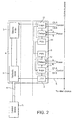
Fig. 2 shows a modification of what is shown inFig. 1 , being an example of the present invention; -
Fig. 3 shows in more detail one of the electronic modules ofFig. 2 ; -
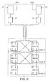
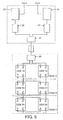
Figs. 4 and5 show the switching of relays in modules for two chokes; -
Fig. 6 shows how redundancy is provided in control channels in an example of the present invention; -
Figs. 7-9 show alternative embodiments of the control channel arrangement; and -
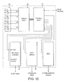
Fig. 10 shows a typical downhole electronics module (DEM) according to the invention. -
Fig. 1 shows, diagrammatically, a known form of drive assembly for a fluid control device, typically a choke, mounted downhole in a hydrocarbon extraction well. The output of the drive is ashaft 1 with a linear motion which operates the fluid control device D, typically a choke having a sliding slotted sleeve that controls fluid flow. The linear action of theshaft 1 is derived from the rotary motion of a motor via a screw arrangement. The assembly (as inGB 2350659 motors mechanism 4, that provides the required linear output from theshaft 1 from either motor. The two motors provide greater availability in the event of the failure of one of them and are controlled and powered via separate feeds from a control system at a surface platform to the well. In the example shown,motor 2 is electric andmotor 3 is hydraulic, thus continuing to provide availability in the case of failure of either the electric or hydraulic power sources or their feeds. The control of both theelectric motor 2 and thehydraulic motor 3 is through an electronic communication system. - In the case of the
hydraulic motor 3, a hydraulic power supply on aline 5 is switched to themotor 3 by a DCV 6, electrically operated by a downhole electronics module (DEM) 7. The DEM 7 recognizes and acts upon a digital message received from the control system via one of the feeds through an umbilical which is designated 'Channel B' (Ch B). Electric power to theDEM 7 is provided by a power supply unit (PSU) 8 which is provided with electric power via the same umbilical and is designated 'Power B'. - Likewise, in the case of the electric drive, the
motor 2 is operated directly by another DEM 9, which recognizes and acts upon a digital message received from the control system via another feed in the umbilical and is designated 'Channel A' (Ch A). Electric power to the DEM 9 is provided by aPSU 10 which is fed with electric power via the same umbilical and is designated 'Power A'. - Although the known system described above provides considerable redundancy, it could be considered as less than adequate when a plurality of fluid control devices D such as chokes are fitted downhole, in that a failure of electrical links between the devices could render the well inoperative. Thus, a system is desired that continues to provide redundancy in the event of such failures. Since both control signals and electric power are equally important in sustaining well control, this invention provides a solution to the failure of either or both.
- In order to provide redundancy of power supply, an embodiment of the invention modifies the DEMs of
Fig. 1 as shown inFig. 2 , by the addition of power supply selection and isolation relay assemblies, the cross-connection between drives of the power supply units (PSUs), the feeding of both 'Power A' and 'Power B' to the relay assemblies and the feeding of both control channels Channel A and Channel B to the DEMs. - Referring to
Fig. 2 , a modifiedDEM 11 for DCV 6 now includes arelay assembly 12 and likewise a modifiedDEM 13 formotor 2 includes arelay assembly 14. Power from PSU8 is applied toDEM 13 and power fromPSU 10 is applied toDEM 11, the latter using one of 'Power A' and 'Power B' andDEM 13 using the other of 'Power A' and 'Power B' in normal operation. Since the normal operation of the system is to operate each of the two drives from a different one of the two power sources, the cross-connected PSUs allow for selection of an alternative power source by a DEM. - The reason for the cross-connection of the
PSUs relay unit 14 to feed thePSU 10. Also assume that "Power A' is powering the system. Now, ifPSU 10 fails then the power to the control logic electronics inDEM 13 would disappear and thus it would be unable to select, as an alternative, 'Power B' to continue operation. By cross-connecting thePSUs DEM 13 operates therelay unit 14 such thatPSU 10 is fed with, say, 'Power A' and the control logic electronics withinDEM 11 operates therelay unit 12 such that thePSU 8 is fed with 'Power B', then, in the event of either a PSU or power source failure, the control logic elements are still powered by the other source and thus able to continue to receive commands to switch the power source to sustain operation of at least one drive. -
Fig. 3 shows the arrangement of the relays in the relay assembly of a modified DEM,i.e. item Fig. 2 . Alatching relay 15 provides selection of the power supply, i.e. 'Power A' or 'Power B', under the control of the electronic part of the DEM. Alatching relay 16 provides switching or isolation of the power feed output to another relay assembly on another choke. Alatching relay 17 provides switching or isolation of power to the PSU,i.e. item Fig. 2 . - As shown in
Fig. 2 , the choke carries two DEMs. When there is a plurality of chokes in a well, the relay assemblies are connected as illustrated inFig. 4. Fig. 4 shows relay assemblies choke choke 21. Power supplies, 'Power A' and 'Power B', are connected to and routed through the two DEM relay assemblies as shown. The twooutput isolation relays 16a ofassemblies second choke 21.Fig. 4 shows clearly which electronic section of the DEMs (11a and 13a forchoke Fig. 5 . -
Fig. 5 shows, as an example, how power can be sustained to both DEMs in thesecond choke 21, and any subsequent chokes (not shown in the figure), in the event of a short or open circuit of anelectrical link 22 between the two chokes. With such a failure, a digital control message is sent to theDEM 11a inchoke 20 which operatesrelay 16a in therelay assembly 19a in thechoke 20. Operation ofrelay 16a isolates choke 21 from the faulty link. This action is followed by a digital control message being sent to theDEM 11b inchoke 21 which operates therelay 15b inrelay assembly 19b ofchoke 21. This reconnects power from the 'Power A' so that both drives continue to operate inchoke 21. - It follows from analysis of the circuit that the failure of any one power link between the chokes or a failure of a power source can be circumvented by suitable operation of the appropriate relays. However this power supply architecture is of limited value unless the same versatility is available, in the event of a failure, for the communication links that control the relays and command the choke drive operation.
-
Fig. 6 shows a typical arrangement for the architecture of the communications system of a subsea well. Communication from the surface platform is duplicated via the umbilical (or via two umbilicals) as Ch A and Ch B. Typically, communication data is transmitted on the power feed and then extracted at the duplicated subsea electronic modules (SEM) 25 located on the well tree on the sea bed. The data is then transformed into the format required to communicate downhole to the choke drives by theinterface units 26. Each choke has two DEMs (DEM 1A andDEM 1B) which contain electronic circuitry that reconfigures the architecture in the case of a fault. These circuits are integrated into integrated circuits, for example communication ASICS ("Application Specific Integrated Circuits"), each with four ports P0, P1, P2, P3. - Under normal, no fault, conditions the communications operates in 'loop mode', with full duplex traffic, of frames of data with a token system. Each integrated circuit operates such that an input to P0 is retransmitted from both P0 and P3, and an input to P3 is retransmitted from P3 and P0. Thus communication is passed round the loop such that any choke can be operated from one channel or the other, in the event of a failure of one link between the chokes.
- However, a much improved fault tolerant system is achieved by additional features in the integrated circuits with the ports cross-connected as shown. In the event of a fault, the integrated circuits are operated in half duplex mode. This is also the start- up mode. In half duplex mode the integrated circuits communicate as to the table below:
RECEIVE ON REPLY ON RE-TRANSMIT ON P0 P0 P3 P1 P1 P1 P2 P0 P2 P2 P3 P1 P3 P3 P2 P0 - Thus in the half duplex mode each DEM will repeat data from the DEM above it, to the DEM below it, i.e. from port P0 to P3. Similarly, each DEM will repeat data from the DEM below it to the DEM above, i.e. from port P3 to P0. Data that is repeated on port P3 of
DEMs - Because of the local cross-loop in each choke, each DEM will actually receive data on two ports. However, the data is delayed by an extra 1.5 bits from the companion DEM and is then not used unless there is a fault. Thus, for example, if there is a fault in the cable (short or open circuit) between
DEM 1A andDEM 2A, thenDEM 2A receives its data on P2 fromDEM 2B.DEM 2A will continue to re-transmit to P3 and P1, so data arrives atDEM 3A port P0. Similarly, if a fault occurs betweenDEM 1B andDEM 2B, thenDEM 2B receives its data on P2 fromDEM 2A.DEM 2B will continue to re-transmit to P3 and P1 so data arrives atDEM 3B port P0. It should be noted that the local cross links in each choke are not in a high stress environment and are thus unlikely to fail. It follows that any single fault between chokes is tolerated and that multiple faults are also tolerated, provided there is only one fault between chokes. - If normal communication is restored, the system automatically switches to full duplex mode.
-
Fig. 7 shows an alternative embodiment suitable for use where there may be only a single "penetration", i.e. a single line leading from the well head through the tubing hangar to the downhole electronics. In this case, communication through the hangar can be achieved by use ofdiplexers - A further variation is also shown in
Fig. 7 wherein the last integrated circuit in the chain (i.e. for choke C) also has cross-connection of the ports P2 and P1. This provides for circumvention of further faults and thus provides even greater redundancy, i.e. maintainability at the expense of reliability. This variation is also equally applicable to the full duplex system ofFig. 6 . -
Fig. 8 shows an embodiment showing an alternative arrangement for achieving redundancy by using a different interconnection of DEMs. Like the example shown inFig. 6 , two penetrations through the hangar are used. In contrast to the system shown inFig.6 , theDEMS DEM 2B is directly connected to Port P0 ofDEM 1B rather than Port P0 ofDEM 3B. The connections between Ports P1 and P2 of the DEMs are maintained however, so that, for example, Port P1 ofDEM 2B is still connected to Port P2 ofDEM 2A. The DEMs themselves function in an identical manner as in the previous embodiments. It can be seen that with this arrangement full redundancy is still provided. -
Fig.9 shows a further embodiment with a similar DEM connection to that shown inFig. 8 , but in this embodiment there is only a single penetration from the well head through the tubing hangar, similar to the embodiment shown inFig. 7 . As in that embodiment, diplexers 27 and 28 are used to respectively combine and re-divide the combined control signals. - An arrangement of a typical DEM according to the invention is shown in
Fig. 10 , to show how the communications architecture provides redundancy of the control of the choke drives. Theintegrated circuit 29, in this case a communications ASIC, has ports P0 to P4 which interface withline drivers 30. The communications ASIC also interfaces with asecond ASIC 31, a profibus ASIC with a standard profibus interface. This interface can be connected to other profibus ASICs if required to expand the system. The profibus ASIC has a number of interfaces which can provide facilities as required for downhole tasks. These include interfaces such as a serial interface and an analogue to digital facility which provides conversion of downhole pressure and temperature measurements to digital code for transmission. A further interface is a standard parallel output which is used to control the operation of the chokc electric motor via theDC motor controller 32 and the DCVs via thedriver unit 33 to operate the hydraulic motor. - Other variations are possible within the scope of the invention which will be apparent to the skilled practitioner. For example, a single loop system may be used instead of the double loop system described. A half duplex system only may be used, with no mode switching as described. The arrangement of the wiring through the tubing hangar can be made in a way which increases fault tolerance, for example the four pairs used for communication can be passed through the tubing hangar in two tubes, such that pairs A 1 and
B 1 pass through a first tube and pairs A2 and B2 pass through a second tube. This further enhances the fault tolerance. In addition, the local profibus fieldbus loop in a DEM can be made redundant, which also further increases the fault tolerance. - It should be noted that although the invention has been illustrated by its application to the control of downhole chokes, it can be equally applicable to the control of other downhole devices.
- The combination of the described power and communication architecture substantially improves fault tolerance in the electrical control of subsea wells.
Claims (2)
- Apparatus for controlling a fluid well, comprising:a) a control device (D) for location downhole;b) first drive means (2) for operating the control device;c) second drive means (3) for operating the control device, the control device being operable selectively by the first and second drive means;d) first power supply means (A);e) second power supply means (B);f) first switching means (13), for switching power to the first drive means; andg) second switching means (11) for switching power to the second drive means; characterised in thati) the first and second power supply means are connected to the first switching means and also to the second switching means, the arrangement being such that, in normal operation, power from the first power supply means powers the first drive means via the first switching means and power from the second power supply means powers the second drive means via the second switching means, and in the event of a fault, power from the first power supply means powers the second drive means or power from the second power supply means powers the first drive means.
- Apparatus according to Claim 1, wherein, in normal operation, power from the first power supply means is provided to the first switching means from the second switching means and power from the second power supply means is provided to the second switching means from the first switching means.
Applications Claiming Priority (2)
| Application Number | Priority Date | Filing Date | Title |
|---|---|---|---|
| GB0328440A GB2408987B (en) | 2003-12-09 | 2003-12-09 | Controlling a fluid well |
| PCT/GB2004/004961 WO2005056980A1 (en) | 2003-12-09 | 2004-11-25 | Controlling a fluid well |
Publications (2)
| Publication Number | Publication Date |
|---|---|
| EP1702136A1 EP1702136A1 (en) | 2006-09-20 |
| EP1702136B1 true EP1702136B1 (en) | 2008-03-19 |
Family
ID=30129838
Family Applications (1)
| Application Number | Title | Priority Date | Filing Date |
|---|---|---|---|
| EP04798666A Expired - Fee Related EP1702136B1 (en) | 2003-12-09 | 2004-11-25 | Controlling a fluid well |
Country Status (5)
| Country | Link |
|---|---|
| US (1) | US20050121188A1 (en) |
| EP (1) | EP1702136B1 (en) |
| GB (2) | GB2408987B (en) |
| NO (1) | NO20061428L (en) |
| WO (1) | WO2005056980A1 (en) |
Families Citing this family (7)
| Publication number | Priority date | Publication date | Assignee | Title |
|---|---|---|---|---|
| CA2581581C (en) | 2006-11-28 | 2014-04-29 | T-3 Property Holdings, Inc. | Direct connecting downhole control system |
| US8196649B2 (en) | 2006-11-28 | 2012-06-12 | T-3 Property Holdings, Inc. | Thru diverter wellhead with direct connecting downhole control |
| US9376894B2 (en) | 2009-11-19 | 2016-06-28 | Onesubsea Ip Uk Limited | Control and supply unit |
| DK2909442T3 (en) * | 2013-01-22 | 2021-05-10 | Halliburton Energy Services Inc | Cross-communication between electronic circuits and electrical devices in well tools |
| GB2545197B (en) * | 2015-12-08 | 2019-02-20 | Aker Solutions As | Workover safety system |
| NO342043B1 (en) | 2015-12-08 | 2018-03-19 | Aker Solutions As | Workover Safety System |
| CN113359408B (en) * | 2021-04-13 | 2022-07-05 | 中国石油大学(华东) | Full-electric-control intelligent redundancy control system for underground safety valve |
Family Cites Families (8)
| Publication number | Priority date | Publication date | Assignee | Title |
|---|---|---|---|---|
| US3404856A (en) * | 1961-11-14 | 1968-10-08 | Boeing Co | Automatic stabilization of aircraft |
| AU1667997A (en) * | 1996-04-04 | 1997-10-09 | Baker Hughes Incorporated | Valve actuator |
| DE69833091D1 (en) * | 1998-09-03 | 2006-03-30 | Cooper Cameron Corp | activation module |
| US6149683A (en) * | 1998-10-05 | 2000-11-21 | Kriton Medical, Inc. | Power system for an implantable heart pump |
| GB9913037D0 (en) * | 1999-06-05 | 1999-08-04 | Abb Offshore Systems Ltd | Actuator |
| US6655125B2 (en) * | 2001-12-05 | 2003-12-02 | Honeywell International Inc. | System architecture for electromechanical thrust reverser actuation systems |
| WO2003060364A1 (en) * | 2002-01-18 | 2003-07-24 | Abb Patent Gmbh | Method and system for propelling a sliding body by means of a bi-directional, linear magnetic drive |
| GB2387977B (en) * | 2002-04-17 | 2005-04-13 | Abb Offshore Systems Ltd | Control of hydrocarbon wells |
-
2003
- 2003-12-09 GB GB0328440A patent/GB2408987B/en not_active Expired - Lifetime
- 2003-12-09 GB GB0611818A patent/GB2427221B/en not_active Expired - Lifetime
-
2004
- 2004-07-09 US US10/887,769 patent/US20050121188A1/en not_active Abandoned
- 2004-11-25 WO PCT/GB2004/004961 patent/WO2005056980A1/en not_active Ceased
- 2004-11-25 EP EP04798666A patent/EP1702136B1/en not_active Expired - Fee Related
-
2006
- 2006-03-29 NO NO20061428A patent/NO20061428L/en unknown
Also Published As
| Publication number | Publication date |
|---|---|
| GB0611818D0 (en) | 2006-07-26 |
| NO20061428L (en) | 2006-09-08 |
| GB0328440D0 (en) | 2004-01-14 |
| US20050121188A1 (en) | 2005-06-09 |
| GB2427221A (en) | 2006-12-20 |
| GB2427221B (en) | 2007-02-07 |
| EP1702136A1 (en) | 2006-09-20 |
| GB2408987A (en) | 2005-06-15 |
| WO2005056980A1 (en) | 2005-06-23 |
| GB2408987B (en) | 2006-11-15 |
Similar Documents
| Publication | Publication Date | Title |
|---|---|---|
| WO2002072999A1 (en) | Power connection to and/or control of wellhead trees | |
| US10202839B2 (en) | Power and communications hub for interface between control pod, auxiliary subsea systems, and surface controls | |
| US7520321B2 (en) | Redundant systems for downhole permanent installations | |
| KR102533931B1 (en) | Hydraulic Reconfigurable and Subsea Repairable Control Systems for Deepwater Blowout Arrestors | |
| EP2909442B1 (en) | Cross-communication between electronic circuits and electrical devices in well tools | |
| KR102471843B1 (en) | Safety integrity levels(sil) rated system for blowout preventer control | |
| NO343588B1 (en) | Control systems and methods for underwater activities. | |
| WO2002076825A3 (en) | Control and energy supply system for at least two aircraft seats | |
| GB2427221A (en) | Controlling a well fluid using built-in redundancy | |
| EP1355037B1 (en) | Control of hydrocarbon wells | |
| WO2000046616A1 (en) | A method of saving a string of tools installed in an oil well, and a corresponding transmission assembly | |
| CN111555662B (en) | Motor control system, motor control device | |
| US7650943B2 (en) | Hydraulic control system | |
| KR102455750B1 (en) | SIL rated system for blowout arrester control | |
| KR102014691B1 (en) | Remote input-output apparatus for industrial controllers with duplicated power and compler module | |
| US8804855B2 (en) | Network infrastructure for mobile machines which can be used in areas at risk of explosion | |
| JP2022069412A (en) | Control device with protection module | |
| KR100741522B1 (en) | Failsafe Switching Device for Railway Signal | |
| US7709978B2 (en) | System interface and installation with the system interface | |
| CN112130449B (en) | Redundancy control system and method thereof | |
| CN100513746C (en) | Support controller for controlling movement of support unit in mine working face | |
| KR100865286B1 (en) | Faulty I / O module replacement system and method | |
| EP2390460B1 (en) | Extending the life of a compromised umbilical | |
| NO20150099A1 (en) | Subsea safety system | |
| JP2007134906A (en) | Monitor control device |
Legal Events
| Date | Code | Title | Description |
|---|---|---|---|
| PUAI | Public reference made under article 153(3) epc to a published international application that has entered the european phase |
Free format text: ORIGINAL CODE: 0009012 |
|
| 17P | Request for examination filed |
Effective date: 20060329 |
|
| AK | Designated contracting states |
Kind code of ref document: A1 Designated state(s): FR GB |
|
| RBV | Designated contracting states (corrected) |
Designated state(s): FR |
|
| DAX | Request for extension of the european patent (deleted) | ||
| 17Q | First examination report despatched |
Effective date: 20070322 |
|
| GRAP | Despatch of communication of intention to grant a patent |
Free format text: ORIGINAL CODE: EPIDOSNIGR1 |
|
| RIN1 | Information on inventor provided before grant (corrected) |
Inventor name: DOUGLAS, NEIL Inventor name: YAGHMAI, SOHRAB Inventor name: JOHANNESSEN, SVEIN Inventor name: ASSKILDT, KNUT |
|
| GRAS | Grant fee paid |
Free format text: ORIGINAL CODE: EPIDOSNIGR3 |
|
| GRAA | (expected) grant |
Free format text: ORIGINAL CODE: 0009210 |
|
| AK | Designated contracting states |
Kind code of ref document: B1 Designated state(s): FR |
|
| RBV | Designated contracting states (corrected) |
Designated state(s): FR |
|
| ET | Fr: translation filed | ||
| PLBE | No opposition filed within time limit |
Free format text: ORIGINAL CODE: 0009261 |
|
| STAA | Information on the status of an ep patent application or granted ep patent |
Free format text: STATUS: NO OPPOSITION FILED WITHIN TIME LIMIT |
|
| 26N | No opposition filed |
Effective date: 20081222 |
|
| REG | Reference to a national code |
Ref country code: FR Ref legal event code: ST Effective date: 20090731 |
|
| PG25 | Lapsed in a contracting state [announced via postgrant information from national office to epo] |
Ref country code: FR Free format text: LAPSE BECAUSE OF NON-PAYMENT OF DUE FEES Effective date: 20081130 |