EP1701209A1 - Liquid crystal screen - Google Patents
Liquid crystal screen Download PDFInfo
- Publication number
- EP1701209A1 EP1701209A1 EP04820693A EP04820693A EP1701209A1 EP 1701209 A1 EP1701209 A1 EP 1701209A1 EP 04820693 A EP04820693 A EP 04820693A EP 04820693 A EP04820693 A EP 04820693A EP 1701209 A1 EP1701209 A1 EP 1701209A1
- Authority
- EP
- European Patent Office
- Prior art keywords
- liquid crystal
- transmittance
- crystal screen
- screen
- voids
- Prior art date
- Legal status (The legal status is an assumption and is not a legal conclusion. Google has not performed a legal analysis and makes no representation as to the accuracy of the status listed.)
- Withdrawn
Links
- 239000004973 liquid crystal related substance Substances 0.000 title claims abstract description 111
- 238000002834 transmittance Methods 0.000 claims description 69
- 239000000463 material Substances 0.000 claims description 10
- 239000000758 substrate Substances 0.000 claims description 4
- 239000007788 liquid Substances 0.000 abstract description 13
- 239000002775 capsule Substances 0.000 abstract description 12
- 239000004816 latex Substances 0.000 abstract description 11
- 229920000126 latex Polymers 0.000 abstract description 11
- 229920002799 BoPET Polymers 0.000 abstract description 9
- 229920006254 polymer film Polymers 0.000 abstract description 5
- 239000000839 emulsion Substances 0.000 description 10
- 238000004519 manufacturing process Methods 0.000 description 9
- 239000004988 Nematic liquid crystal Substances 0.000 description 7
- 239000003431 cross linking reagent Substances 0.000 description 5
- 230000000052 comparative effect Effects 0.000 description 4
- 238000010276 construction Methods 0.000 description 3
- 238000004132 cross linking Methods 0.000 description 3
- 230000003287 optical effect Effects 0.000 description 3
- 239000004094 surface-active agent Substances 0.000 description 3
- 239000008346 aqueous phase Substances 0.000 description 2
- 230000005540 biological transmission Effects 0.000 description 2
- 239000011521 glass Substances 0.000 description 2
- 238000002156 mixing Methods 0.000 description 2
- 239000002245 particle Substances 0.000 description 2
- 239000007787 solid Substances 0.000 description 2
- KEQXNNJHMWSZHK-UHFFFAOYSA-L 1,3,2,4$l^{2}-dioxathiaplumbetane 2,2-dioxide Chemical compound [Pb+2].[O-]S([O-])(=O)=O KEQXNNJHMWSZHK-UHFFFAOYSA-L 0.000 description 1
- 239000004986 Cholesteric liquid crystals (ChLC) Substances 0.000 description 1
- 239000004990 Smectic liquid crystal Substances 0.000 description 1
- 239000000084 colloidal system Substances 0.000 description 1
- 230000007423 decrease Effects 0.000 description 1
- 230000003247 decreasing effect Effects 0.000 description 1
- 238000001035 drying Methods 0.000 description 1
- 239000004033 plastic Substances 0.000 description 1
- 229920003023 plastic Polymers 0.000 description 1
- 229920003229 poly(methyl methacrylate) Polymers 0.000 description 1
- 229920000058 polyacrylate Polymers 0.000 description 1
- 229920002239 polyacrylonitrile Polymers 0.000 description 1
- 229920006289 polycarbonate film Polymers 0.000 description 1
- 229920000139 polyethylene terephthalate Polymers 0.000 description 1
- -1 polyethylene terephthalate Polymers 0.000 description 1
- 239000005020 polyethylene terephthalate Substances 0.000 description 1
- 229920000193 polymethacrylate Polymers 0.000 description 1
- 239000004926 polymethyl methacrylate Substances 0.000 description 1
- 238000003756 stirring Methods 0.000 description 1
Images


Classifications
-
- G—PHYSICS
- G02—OPTICS
- G02F—OPTICAL DEVICES OR ARRANGEMENTS FOR THE CONTROL OF LIGHT BY MODIFICATION OF THE OPTICAL PROPERTIES OF THE MEDIA OF THE ELEMENTS INVOLVED THEREIN; NON-LINEAR OPTICS; FREQUENCY-CHANGING OF LIGHT; OPTICAL LOGIC ELEMENTS; OPTICAL ANALOGUE/DIGITAL CONVERTERS
- G02F1/00—Devices or arrangements for the control of the intensity, colour, phase, polarisation or direction of light arriving from an independent light source, e.g. switching, gating or modulating; Non-linear optics
- G02F1/01—Devices or arrangements for the control of the intensity, colour, phase, polarisation or direction of light arriving from an independent light source, e.g. switching, gating or modulating; Non-linear optics for the control of the intensity, phase, polarisation or colour
- G02F1/13—Devices or arrangements for the control of the intensity, colour, phase, polarisation or direction of light arriving from an independent light source, e.g. switching, gating or modulating; Non-linear optics for the control of the intensity, phase, polarisation or colour based on liquid crystals, e.g. single liquid crystal display cells
- G02F1/133—Constructional arrangements; Operation of liquid crystal cells; Circuit arrangements
- G02F1/1333—Constructional arrangements; Manufacturing methods
- G02F1/1334—Constructional arrangements; Manufacturing methods based on polymer dispersed liquid crystals, e.g. microencapsulated liquid crystals
-
- G—PHYSICS
- G03—PHOTOGRAPHY; CINEMATOGRAPHY; ANALOGOUS TECHNIQUES USING WAVES OTHER THAN OPTICAL WAVES; ELECTROGRAPHY; HOLOGRAPHY
- G03B—APPARATUS OR ARRANGEMENTS FOR TAKING PHOTOGRAPHS OR FOR PROJECTING OR VIEWING THEM; APPARATUS OR ARRANGEMENTS EMPLOYING ANALOGOUS TECHNIQUES USING WAVES OTHER THAN OPTICAL WAVES; ACCESSORIES THEREFOR
- G03B21/00—Projectors or projection-type viewers; Accessories therefor
- G03B21/54—Accessories
- G03B21/56—Projection screens
- G03B21/60—Projection screens characterised by the nature of the surface
- G03B21/62—Translucent screens
-
- G—PHYSICS
- G02—OPTICS
- G02F—OPTICAL DEVICES OR ARRANGEMENTS FOR THE CONTROL OF LIGHT BY MODIFICATION OF THE OPTICAL PROPERTIES OF THE MEDIA OF THE ELEMENTS INVOLVED THEREIN; NON-LINEAR OPTICS; FREQUENCY-CHANGING OF LIGHT; OPTICAL LOGIC ELEMENTS; OPTICAL ANALOGUE/DIGITAL CONVERTERS
- G02F1/00—Devices or arrangements for the control of the intensity, colour, phase, polarisation or direction of light arriving from an independent light source, e.g. switching, gating or modulating; Non-linear optics
- G02F1/01—Devices or arrangements for the control of the intensity, colour, phase, polarisation or direction of light arriving from an independent light source, e.g. switching, gating or modulating; Non-linear optics for the control of the intensity, phase, polarisation or colour
- G02F1/13—Devices or arrangements for the control of the intensity, colour, phase, polarisation or direction of light arriving from an independent light source, e.g. switching, gating or modulating; Non-linear optics for the control of the intensity, phase, polarisation or colour based on liquid crystals, e.g. single liquid crystal display cells
-
- G—PHYSICS
- G03—PHOTOGRAPHY; CINEMATOGRAPHY; ANALOGOUS TECHNIQUES USING WAVES OTHER THAN OPTICAL WAVES; ELECTROGRAPHY; HOLOGRAPHY
- G03B—APPARATUS OR ARRANGEMENTS FOR TAKING PHOTOGRAPHS OR FOR PROJECTING OR VIEWING THEM; APPARATUS OR ARRANGEMENTS EMPLOYING ANALOGOUS TECHNIQUES USING WAVES OTHER THAN OPTICAL WAVES; ACCESSORIES THEREFOR
- G03B21/00—Projectors or projection-type viewers; Accessories therefor
- G03B21/54—Accessories
- G03B21/56—Projection screens
-
- G—PHYSICS
- G03—PHOTOGRAPHY; CINEMATOGRAPHY; ANALOGOUS TECHNIQUES USING WAVES OTHER THAN OPTICAL WAVES; ELECTROGRAPHY; HOLOGRAPHY
- G03B—APPARATUS OR ARRANGEMENTS FOR TAKING PHOTOGRAPHS OR FOR PROJECTING OR VIEWING THEM; APPARATUS OR ARRANGEMENTS EMPLOYING ANALOGOUS TECHNIQUES USING WAVES OTHER THAN OPTICAL WAVES; ACCESSORIES THEREFOR
- G03B21/00—Projectors or projection-type viewers; Accessories therefor
- G03B21/54—Accessories
- G03B21/56—Projection screens
- G03B21/60—Projection screens characterised by the nature of the surface
- G03B21/608—Fluid screens
Definitions
- the present invention relates to a liquid crystal screen, and in particular relates to a transmission type liquid crystal screen onto which an image is projected from behind.
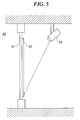
- a display system 50 as shown in FIG. 5 comprised of a transmission type polarizing diffracting screen 52 made of plastic bonded to an inside surface of glass 51 of a show window, and an image projector 53 installed indoors that projects an image onto the polarizing diffracting screen 52 at a predetermined angle of incidence has been known from hitherto as an advertising medium used instead of a poster printed on paper.
- the polarizing diffracting screen 52 diffracts and transmits the image projected from indoors so that the image appears on a surface of the polarizing diffracting screen 52 facing outdoors.
- a diffraction grating that horizontally polarizes and diffracts the image projected at the predetermined angle of incidence is formed in the polarizing diffracting screen 52 (see, for example, Published Patent Application of Japan (Kokai) No. 2002-107832 ).
- Such a diffraction grating is generally constituted from many fine grooves arranged parallel to one another and at an equal spacing, and hence the diffraction grating in the polarizing diffracting screen 52 is manufactured through microfabrication, for example irradiation with a laser having a pulse width of not more than 10 to 12 seconds (see, for example, Published Patent Application of Japan (Kokai) No. 2003-195023 ).
- the values of the size and spacing of the grooves formed in the diffraction grating are fixed values, and hence there is a problem that only an image projected at the predetermined angle of incidence can be shown clearly, it not being possible to clearly show an image projected at another angle of incidence (hereinafter this problem is referred to as "the incidence angle dependence of image quality").
- the present invention has been devised in view of the above problems. It is an object of the present invention to provide a liquid crystal screen, which can be easily manufactured so that an increase in cost can be prevented, and enables the incidence angle dependence of image quality to be eliminated.
- a liquid crystal screen comprising a liquid crystal layer, and a pair of transparent substrates that sandwich the liquid crystal layer therebetween, wherein the liquid crystal layer has a plurality of voids therein, each of the voids being filled with a liquid crystal material.
- the variation in transmittance defined as the difference between the maximum transmittance and the minimum transmittance among transmittances at wavelengths in a predetermined wavelength region of incident light for the liquid crystal layer is set to be within a predetermined range.
- a converted diameter D1 of a sphere having the same volume as the volume of one of the voids is not less than 1.5 ⁇ m.
- the birefringence ⁇ n of the liquid crystal material is not less than 0.12.
- the product of the converted diameter D1 and the birefringence ⁇ n is in a range 0.24 ⁇ m ⁇ D1 ⁇ n ⁇ 0.32 ⁇ m.
- a liquid crystal screen of an embodiment of the present invention will now be described with reference to the drawings.
- FIG. 1 is a sectional view schematically showing the construction of a liquid crystal screen according to an embodiment of the present invention.
- the liquid crystal screen 10 is comprised of a liquid crystal layer 14 that is comprised of a transparent polymer film 11 made of a latex having a plurality of voids therein and liquid crystal capsules 13 formed through the voids being filled with nematic liquid crystalline rod-like molecules 12, and a pair of polyethylene terephthalate films (hereinafter referred to as "PET films”) 15a and 15b that sandwich the liquid crystal layer 14 therebetween.
- PET films polyethylene terephthalate films
- the nematic liquid crystalline rod-like molecules 12 line up along curved surfaces of walls of the liquid crystal capsules 13, the direction of alignment of the nematic liquid crystalline rod-like molecules 12 in each of the liquid crystal capsules 13 being random.
- the randomly aligned nematic liquid crystalline rod-like molecules 12 bend the optical path of incident light transmitted through the liquid crystal layer 14 in random directions.
- the liquid crystal screen 10 is thus milk-white color when an image or the like is not being projected thereon, whereas when an image or the like is being projected thereon, the incident light is scattered in random directions regardless of the angle of incidence of the image.
- liquid crystal screen 10 of the incident light scattered in random directions, some is transmitted through the liquid crystal screen 10 to the opposite surface to the surface on which the image is being projected, whereby the image appears on this opposite surface.
- the above scattering of the incident light arises through the incident light being diffracted by the nematic liquid crystalline rod-like molecules 12, and hence incident light of a long wavelength at which diffraction does not readily occur is not readily scattered.
- light of long wavelength such as red light is preferentially transmitted, and hence the image appearing on the liquid crystal screen 10 may have a reddish tinge (hereinafter this is referred to as "the wavelength dependence of the hue of the transmitted light").
- the converted diameter D1 To reduce the wavelength dependence of the hue of the transmitted for the liquid crystal screen 10, it is thus necessary to set the converted diameter D1 to not less than a predetermined value, thus keeping down the difference between the maximum transmittance and the minimum transmittance among the transmittances at wavelengths in a predetermined wavelength region of the incident light such as the visible region (hereinafter referred to as "the variation in the transmittance") to within a predetermined range, thereby preventing light of long wavelength from being preferentially transmitted.
- the variation in the transmittance over the visible region from 380 to 780 nm which accounts for the majority of the wavelength region of the incident light can be kept down to not more than 3%, and hence the wavelength dependence of the hue of the transmitted light can be reduced.
- the transmittance generally increases as the wavelength increases, and hence the variation in the transmittance over the region from 380 to 780 nm is the difference between the transmittance at 780 nm and the transmittance at 380 nm.
- the converted diameter D1 there is a correlation between the converted diameter D1 and the birefringence ⁇ n of the nematic liquid crystalline rod-like molecules 12, in general it being necessary to increase the set value of the converted diameter D1 to reduce the birefringence ⁇ n.
- the converted diameter D1 must be set in a range of 1.5 ⁇ m to 2.0 ⁇ m, and to achieve a birefringence ⁇ n of 0.12, the converted diameter D1 must be set in a range of 2.0 ⁇ m to 2.7 ⁇ m.
- the incident light is scattered in random directions as described above, and the transmittance varies with the scattering direction, specifically the transmittance decreases as the scattering direction widens out from the normal direction to the surface of the liquid crystal screen 10, i.e. as the scattering angle increases.
- the image appearing on the liquid crystal screen 10 may become unclear depending on the direction from which an observer views the liquid crystal screen 10 (hereinafter this is referred to as "the scattering angle dependence of the transmittance").
- the birefringence ⁇ n must thus be set to not less than a predetermined value.
- the scattering angle dependence of the transmittance can be reduced to a sufficient level for securing functionality of the liquid crystal screen.
- the converted diameter D1 is set to not less than 1.5 ⁇ m and the birefringence ⁇ n is set to not less than 0.12, in particular the product of the converted diameter D1 and the birefringence ⁇ n is set to be in a range of 0.24 ⁇ m to 0.32 ⁇ m.
- FIG. 2 is a flowchart showing a method of manufacturing the liquid crystal screen 10 shown in FIG. 1.
- nematic liquid crystals and an aqueous phase are mixed together to prepare an emulsion, and the prepared emulsion is added to a latex, or else nematic liquid crystals and a latex are directly mixed together to prepare an emulsion (step S21).
- a surfactant to the emulsion.
- the mixing together of the nematic liquid crystals and the aqueous phase or the latex is carried out using a mixer such as a blender or a colloid mill.
- the converted diameter D1 of the liquid crystal capsules 13 can be controlled to a desired value through the rotational speed of the mixer.
- the converted diameter D1 is set to 2.0 ⁇ m; in the case that the converted diameter D1 is 2.0 ⁇ m, the birefringence ⁇ n of the nematic liquid crystals will be in a range of 0.12 to 0.16.
- a crosslinking agent for crosslinking the latex in the prepared emulsion is added to the emulsion to form a medium (step S22).
- the amount added of the crosslinking agent is set, in correspondence with the amount of solid contents in the latex, to be an amount capable of crosslinking all of the latex in terms of solids.
- the medium thus formed is then applied onto a 175 ⁇ m-thick PET film 15a using suitable means such as a knife blade, and the applied medium is then dried, whereby crosslinking of the latex by the crosslinking agent is made to proceed, and hence a liquid crystal layer 14 is formed (step S23).
- a PET film 15b is stuck onto the liquid crystal layer 14 thus formed (step S24), thus completing the manufacturing process.
- the liquid crystal screen is comprised of the liquid crystal layer 14 that is comprised of the transparent polymer film 11 made of a latex having a plurality of voids therein and the liquid crystal capsules 13 formed through the voids being filled with the nematic liquid crystalline rod-like molecules 12, and the pair of PET films 15a and 15b that sandwich the liquid crystal layer 14 therebetween.
- manufacture is easy, and hence an increase in cost can be prevented.
- the variation in the transmittance of the incident light over a visible region is set to be within a predetermined range, specifically the converted diameter D1 is set to not less than 1.5 ⁇ m so that the variation in the transmittance over the visible region from 380 to 780 nm which accounts for the majority of the wavelength region of the incident light is kept down to not more than 3%.
- the wavelength dependence of the hue of the transmitted light can be reduced, and hence light of long wavelength being preferentially transmitted so that the image appearing on the liquid crystal screen 10 has a reddish tinge can be suppressed to within a range so as not to be a problem in practice.
- the birefringence ⁇ n of the nematic liquid crystalline rod-like molecules 12 is not less than 0.12. As a result, the difference between the transmittance at a large scattering angle and the transmittance in the normal direction is reduced, and hence the scattering angle dependence of the transmittance can be reduced to a sufficient level for securing functionality of the liquid crystal screen.
- the product of the converted diameter D1 and the birefringence ⁇ n is set to be in a range of 0.24 ⁇ m to 0.32 ⁇ m.
- nematic liquid crystals are used as the liquid crystal material.
- cholesteric liquid crystals, smectic liquid crystals, or the like may be used instead of nematic liquid crystals.
- PET films 15 are used as the transparent substrates.
- glass sheets, or else polymer films (polycarbonate films, polyacrylonitrile films, polyacrylate films, polymethacrylate films, polymethyl methacrylate films, etc.) or the like may be used instead of PET films.
- a material of any type, inorganic or organic may be used, so long as the nematic liquid crystals can be held in this material in the form of a plurality of capsules.
- the converted diameter D1 of the liquid crystal capsules was 2.0 ⁇ m, and D1 ⁇ n was 0.286 ⁇ m.
- the transmittance of the liquid crystal screen over a wavelength region from 380 nm to 800 nm was measured using an MCPD-100 (28C) multifunctional multichannel spectrophotometer (made by Otsuka Electronics Co., Ltd.). The results are shown by the dashed line on the graph of FIG. 3, described below.
- the transmittance at scattering angles from -50° to 50° was measured.
- the ratio of the transmittance at each scattering angle to the transmittance in a normal direction (0°) (hereinafter referred to as "the scattering transmittance ratio") is shown by the dashed line on the graph of FIG. 4, described below.
- a liquid crystal screen was obtained using the same manufacturing method as in Example 1 described above, except that the rotational speed of the homogenizer was set to a different value to that in Example 1.
- the converted diameter D1 of the liquid crystal capsules was 1.0 ⁇ m, and D1 ⁇ n was 0.143.
- Example 1 the transmittance over a wavelength region from 380 nm to 800 nm was measured as for Example 1 described above. The results are shown by the full line on the graph of FIG. 3, described below. Moreover, the transmittance at scattering angles from -50° to 50° was measured. The scattering transmittance ratio is shown by the full line on the graph of FIG. 4, described below.
- FIG. 3 is a graph showing the transmittance of the liquid crystal screens over a wavelength region from 380 nm to 800 nm.
- the axis of abscissas shows the wavelength of incident light
- the axis of ordinates shows the transmittance at each wavelength
- the difference between the transmittance at a wavelength of 780 nm, which is the maximum transmittance, and the transmittance at a wavelength of 380 nm, which is the minimum transmittance, is kept down to not more than 3%.
- the variation in the transmittance can be kept down to within a range such that there are no problems in practice, i.e. the wavelength dependence of the hue of the transmitted light can be reduced. Accordingly, it was found that for the liquid crystal screen of Example 1, an image does not have a reddish tinge.
- FIG. 4 is a graph showing the relationship between the transmittance at various scattering angles from -50° to 50°, and the transmittance in the normal direction (0°) for each of the liquid crystal screens.
- the axis of abscissas shows the scattering angle of scattered light
- the axis of ordinates shows the scattering transmittance ratio
- a liquid crystal screen is comprised of a liquid crystal layer, and a pair of transparent substrates that sandwich the liquid crystal layer therebetween, wherein the liquid crystal layer has a plurality of voids therein, each of the voids being filled with a liquid crystal material.
- the variation in transmittance defined as the difference between the maximum transmittance and the minimum transmittance among transmittances at wavelengths in a predetermined wavelength region of the incident light for the liquid crystal layer is set to be within a predetermined range.
- a converted diameter D1 of a sphere having the same volume as the volume of one of the voids is not less than 1.5 ⁇ m.
- the birefringence ⁇ n of the liquid crystal material is not less than 0.12.
- the product of the converted diameter D1 and the birefringence ⁇ n is in a range 0.24 ⁇ m ⁇ D1 ⁇ n ⁇ 0.32 ⁇ m.
Landscapes
- Physics & Mathematics (AREA)
- Nonlinear Science (AREA)
- General Physics & Mathematics (AREA)
- Chemical & Material Sciences (AREA)
- Crystallography & Structural Chemistry (AREA)
- Optics & Photonics (AREA)
- Dispersion Chemistry (AREA)
- Mathematical Physics (AREA)
- Liquid Crystal (AREA)
- Overhead Projectors And Projection Screens (AREA)
- Optical Elements Other Than Lenses (AREA)
Abstract
Description
- The present invention relates to a liquid crystal screen, and in particular relates to a transmission type liquid crystal screen onto which an image is projected from behind.
- A
display system 50 as shown in FIG. 5 comprised of a transmission type polarizing diffractingscreen 52 made of plastic bonded to an inside surface ofglass 51 of a show window, and animage projector 53 installed indoors that projects an image onto the polarizing diffractingscreen 52 at a predetermined angle of incidence has been known from hitherto as an advertising medium used instead of a poster printed on paper. According to such adisplay system 50, the polarizing diffractingscreen 52 diffracts and transmits the image projected from indoors so that the image appears on a surface of the polarizing diffractingscreen 52 facing outdoors. A diffraction grating that horizontally polarizes and diffracts the image projected at the predetermined angle of incidence is formed in the polarizing diffracting screen 52 (see, for example, Published Patent Application ofJapan (Kokai) No. 2002-107832 - Such a diffraction grating is generally constituted from many fine grooves arranged parallel to one another and at an equal spacing, and hence the diffraction grating in the polarizing diffracting
screen 52 is manufactured through microfabrication, for example irradiation with a laser having a pulse width of not more than 10 to 12 seconds (see, for example, Published Patent Application ofJapan (Kokai) No. 2003-195023 - However, because microfabrication is required in the manufacture of the diffraction grating as described above, there are problems that the manufacture takes much time, and moreover the yield is decreased and hence the cost increases.
- Moreover, the values of the size and spacing of the grooves formed in the diffraction grating are fixed values, and hence there is a problem that only an image projected at the predetermined angle of incidence can be shown clearly, it not being possible to clearly show an image projected at another angle of incidence (hereinafter this problem is referred to as "the incidence angle dependence of image quality").
- The present invention has been devised in view of the above problems. It is an object of the present invention to provide a liquid crystal screen, which can be easily manufactured so that an increase in cost can be prevented, and enables the incidence angle dependence of image quality to be eliminated.
- To attain the above object, according to the present invention, there is provided a liquid crystal screen comprising a liquid crystal layer, and a pair of transparent substrates that sandwich the liquid crystal layer therebetween, wherein the liquid crystal layer has a plurality of voids therein, each of the voids being filled with a liquid crystal material.
- In the present invention, preferably, the variation in transmittance defined as the difference between the maximum transmittance and the minimum transmittance among transmittances at wavelengths in a predetermined wavelength region of incident light for the liquid crystal layer is set to be within a predetermined range.
- In the present invention, preferably, a converted diameter D1 of a sphere having the same volume as the volume of one of the voids is not less than 1.5 µm.
- In the present invention, preferably, the birefringence Δn of the liquid crystal material is not less than 0.12.
- In the present invention, preferably, the product of the converted diameter D1 and the birefringence Δn is in a range 0.24 µm ≤ D1×Δn ≤ 0.32 µm.
-
- FIG. 1 is a sectional view schematically showing the construction of a liquid crystal screen according to an embodiment of the present invention;
- FIG. 2 is a flowchart showing a method of manufacturing the liquid crystal screen shown in FIG. 1;
- FIG. 3 is a graph showing the transmittance of liquid crystal screens over a wavelength region from 380 nm to 800 nm;
- FIG. 4 is a graph showing the relationship between the transmittance at various scattering angles from -50° to 50°, and the transmittance in a normal direction (0°) for each of the liquid crystal screens; and
- FIG. 5 is a view schematically showing the construction of a conventional display system used as an advertising medium.
- A liquid crystal screen of an embodiment of the present invention will now be described with reference to the drawings.
- FIG. 1 is a sectional view schematically showing the construction of a liquid crystal screen according to an embodiment of the present invention.
- As shown in FIG. 1, the
liquid crystal screen 10 is comprised of aliquid crystal layer 14 that is comprised of atransparent polymer film 11 made of a latex having a plurality of voids therein andliquid crystal capsules 13 formed through the voids being filled with nematic liquid crystalline rod-like molecules 12, and a pair of polyethylene terephthalate films (hereinafter referred to as "PET films") 15a and 15b that sandwich theliquid crystal layer 14 therebetween. - In the
liquid crystal screen 10, the nematic liquid crystalline rod-like molecules 12 line up along curved surfaces of walls of theliquid crystal capsules 13, the direction of alignment of the nematic liquid crystalline rod-like molecules 12 in each of theliquid crystal capsules 13 being random. As a result, the randomly aligned nematic liquid crystalline rod-like molecules 12 bend the optical path of incident light transmitted through theliquid crystal layer 14 in random directions. Theliquid crystal screen 10 is thus milk-white color when an image or the like is not being projected thereon, whereas when an image or the like is being projected thereon, the incident light is scattered in random directions regardless of the angle of incidence of the image. - Moreover, in the
liquid crystal screen 10, of the incident light scattered in random directions, some is transmitted through theliquid crystal screen 10 to the opposite surface to the surface on which the image is being projected, whereby the image appears on this opposite surface. - The above scattering of the incident light arises through the incident light being diffracted by the nematic liquid crystalline rod-
like molecules 12, and hence incident light of a long wavelength at which diffraction does not readily occur is not readily scattered. As a result, light of long wavelength such as red light is preferentially transmitted, and hence the image appearing on theliquid crystal screen 10 may have a reddish tinge (hereinafter this is referred to as "the wavelength dependence of the hue of the transmitted light"). - However, if the size of a converted diameter D1 of a sphere having the same volume as the volume of one of the
liquid crystal capsules 13 is increased, then it becomes that the incident light is not readily transmitted through theliquid crystal screen 10 regardless of the wavelength. - To reduce the wavelength dependence of the hue of the transmitted for the
liquid crystal screen 10, it is thus necessary to set the converted diameter D1 to not less than a predetermined value, thus keeping down the difference between the maximum transmittance and the minimum transmittance among the transmittances at wavelengths in a predetermined wavelength region of the incident light such as the visible region (hereinafter referred to as "the variation in the transmittance") to within a predetermined range, thereby preventing light of long wavelength from being preferentially transmitted. - Specifically, if the converted diameter D1 is not less than 1.5 µm, then the variation in the transmittance over the visible region from 380 to 780 nm which accounts for the majority of the wavelength region of the incident light can be kept down to not more than 3%, and hence the wavelength dependence of the hue of the transmitted light can be reduced. The transmittance generally increases as the wavelength increases, and hence the variation in the transmittance over the region from 380 to 780 nm is the difference between the transmittance at 780 nm and the transmittance at 380 nm.
- Furthermore, there is a correlation between the converted diameter D1 and the birefringence Δn of the nematic liquid crystalline rod-
like molecules 12, in general it being necessary to increase the set value of the converted diameter D1 to reduce the birefringence Δn. Specifically, to achieve a birefringence Δn of 0.16, the converted diameter D1 must be set in a range of 1.5 µm to 2.0 µm, and to achieve a birefringence Δn of 0.12, the converted diameter D1 must be set in a range of 2.0 µm to 2.7 µm. - Moreover, the incident light is scattered in random directions as described above, and the transmittance varies with the scattering direction, specifically the transmittance decreases as the scattering direction widens out from the normal direction to the surface of the
liquid crystal screen 10, i.e. as the scattering angle increases. As a result, the image appearing on theliquid crystal screen 10 may become unclear depending on the direction from which an observer views the liquid crystal screen 10 (hereinafter this is referred to as "the scattering angle dependence of the transmittance"). - However, the greater the birefringence Δn of the nematic liquid crystalline rod-
like molecules 12, the lower the difference tends to be between the transmittance at a large scattering angle and the transmittance in the normal direction. - To reduce the scattering angle dependence of the transmittance for the
liquid crystal screen 10, the birefringence Δn must thus be set to not less than a predetermined value. - Specifically, if the birefringence Δn of the nematic liquid crystalline rod-
like molecules 12 is not less than 0.12, then the scattering angle dependence of the transmittance can be reduced to a sufficient level for securing functionality of the liquid crystal screen. - Accordingly, for the
liquid crystal screen 10, the converted diameter D1 is set to not less than 1.5 µm and the birefringence Δn is set to not less than 0.12, in particular the product of the converted diameter D1 and the birefringence Δn is set to be in a range of 0.24 µm to 0.32 µm. - Next, a description will be given of a method of manufacturing the
liquid crystal screen 10. - FIG. 2 is a flowchart showing a method of manufacturing the
liquid crystal screen 10 shown in FIG. 1. - As shown in FIG. 2, first, nematic liquid crystals and an aqueous phase are mixed together to prepare an emulsion, and the prepared emulsion is added to a latex, or else nematic liquid crystals and a latex are directly mixed together to prepare an emulsion (step S21). At this time, to obtain stable liquid crystal particles, it is preferable to add a surfactant to the emulsion. The mixing together of the nematic liquid crystals and the aqueous phase or the latex is carried out using a mixer such as a blender or a colloid mill. The converted diameter D1 of the
liquid crystal capsules 13 can be controlled to a desired value through the rotational speed of the mixer. Here, the converted diameter D1 is set to 2.0 µm; in the case that the converted diameter D1 is 2.0 µm, the birefringence Δn of the nematic liquid crystals will be in a range of 0.12 to 0.16. - Next, a crosslinking agent for crosslinking the latex in the prepared emulsion is added to the emulsion to form a medium (step S22). The amount added of the crosslinking agent is set, in correspondence with the amount of solid contents in the latex, to be an amount capable of crosslinking all of the latex in terms of solids.
- The medium thus formed is then applied onto a 175 µm-
thick PET film 15a using suitable means such as a knife blade, and the applied medium is then dried, whereby crosslinking of the latex by the crosslinking agent is made to proceed, and hence aliquid crystal layer 14 is formed (step S23). - Next, a
PET film 15b is stuck onto theliquid crystal layer 14 thus formed (step S24), thus completing the manufacturing process. - According to the liquid crystal screen of the present embodiment, the liquid crystal screen is comprised of the
liquid crystal layer 14 that is comprised of thetransparent polymer film 11 made of a latex having a plurality of voids therein and theliquid crystal capsules 13 formed through the voids being filled with the nematic liquid crystalline rod-like molecules 12, and the pair ofPET films liquid crystal layer 14 therebetween. As a result, manufacture is easy, and hence an increase in cost can be prevented. Moreover, the nematic liquid crystalline rod-like molecules 12, which are aligned in a random direction in each of theliquid crystal capsules 13, bend the optical path of incident light in random directions, and as a result the incident light can be scattered in random directions regardless of the angle of incidence of an image, whereby the incidence angle dependence of image quality can be eliminated. - Moreover, according to the
liquid crystal screen 10 described above, the variation in the transmittance of the incident light over a visible region is set to be within a predetermined range, specifically the converted diameter D1 is set to not less than 1.5 µm so that the variation in the transmittance over the visible region from 380 to 780 nm which accounts for the majority of the wavelength region of the incident light is kept down to not more than 3%. As a result, the wavelength dependence of the hue of the transmitted light can be reduced, and hence light of long wavelength being preferentially transmitted so that the image appearing on theliquid crystal screen 10 has a reddish tinge can be suppressed to within a range so as not to be a problem in practice. - Furthermore, according to the
liquid crystal screen 10 described above, the birefringence Δn of the nematic liquid crystalline rod-like molecules 12 is not less than 0.12. As a result, the difference between the transmittance at a large scattering angle and the transmittance in the normal direction is reduced, and hence the scattering angle dependence of the transmittance can be reduced to a sufficient level for securing functionality of the liquid crystal screen. - Moreover, according to the
liquid crystal screen 10 described above, the product of the converted diameter D1 and the birefringence Δn is set to be in a range of 0.24 µm to 0.32 µm. As a result, both a reduction in the scattering angle dependence of the transmittance and a reduction in the wavelength dependence of the hue of the transmitted light can be achieved. - In the
screen 10 described above, nematic liquid crystals are used as the liquid crystal material. However, cholesteric liquid crystals, smectic liquid crystals, or the like may be used instead of nematic liquid crystals. - Moreover, in the
liquid crystal screen 10, PET films 15 are used as the transparent substrates. However, glass sheets, or else polymer films (polycarbonate films, polyacrylonitrile films, polyacrylate films, polymethacrylate films, polymethyl methacrylate films, etc.) or the like may be used instead of PET films. - Furthermore, for the polymer film in the
liquid crystal screen 10, a material of any type, inorganic or organic, may be used, so long as the nematic liquid crystals can be held in this material in the form of a plurality of capsules. - Next, an example of the present invention will be described in detail.
- 0.5 wt% of an Igepal CO-610 surfactant (made by GAF Corporation) was added to ZLI-1840 liquid crystals (made by Merck & Co., Inc., Δn = 0.143), the liquid crystals to which the surfactant had been added were added to NeoRez R-967 (made by AstraZeneca PLC) containing 40 wt% of latex particles such that the liquid crystal proportion was 0.62, and then stirring was carried out for 10 minutes at 1000 revs using a homogenizer, thus obtaining an emulsion. Next, while gently mixing the emulsion, a CX-10 crosslinking agent (made by AstraZeneca PLC) was added in a proportion of 3 wt% to the emulsion. The emulsion to which the crosslinking agent had been added was then applied onto a PET film using a doctor blade, and drying was carried out, thus obtaining a liquid crystal layer. The thickness of the liquid crystal layer was 20 µm.
- Then, another PET film was stuck onto the liquid crystal layer, thus obtaining a liquid crystal screen.
- For the above liquid crystal screen, the converted diameter D1 of the liquid crystal capsules was 2.0 µm, and D1×Δn was 0.286 µm.
- Using the liquid crystal screen, the transmittance of the liquid crystal screen over a wavelength region from 380 nm to 800 nm was measured using an MCPD-100 (28C) multifunctional multichannel spectrophotometer (made by Otsuka Electronics Co., Ltd.). The results are shown by the dashed line on the graph of FIG. 3, described below.
- Moreover, the transmittance at scattering angles from -50° to 50° was measured. The ratio of the transmittance at each scattering angle to the transmittance in a normal direction (0°) (hereinafter referred to as "the scattering transmittance ratio") is shown by the dashed line on the graph of FIG. 4, described below.
- A liquid crystal screen was obtained using the same manufacturing method as in Example 1 described above, except that the rotational speed of the homogenizer was set to a different value to that in Example 1. For the liquid crystal screen obtained, the converted diameter D1 of the liquid crystal capsules was 1.0 µm, and D1×Δn was 0.143.
- Using this liquid crystal screen, the transmittance over a wavelength region from 380 nm to 800 nm was measured as for Example 1 described above. The results are shown by the full line on the graph of FIG. 3, described below. Moreover, the transmittance at scattering angles from -50° to 50° was measured. The scattering transmittance ratio is shown by the full line on the graph of FIG. 4, described below.
- FIG. 3 is a graph showing the transmittance of the liquid crystal screens over a wavelength region from 380 nm to 800 nm.
- In FIG. 3, the axis of abscissas shows the wavelength of incident light, and the axis of ordinates shows the transmittance at each wavelength.
- It can be seen from the graph of FIG. 3 that for the liquid crystal screen of Comparative Example 1, the transmittance increases at long wavelengths, and in particular the transmittance exceeds 8% at a wavelength of 800 nm and above, and the difference between the transmittance at a wavelength of 380 nm and the transmittance at a wavelength of 800 nm is also approximately 8%. As a result, for the liquid crystal screen of Comparative Example 1, an image has a reddish tinge. On the other hand, for the liquid crystal screen of Example 1, there is no such sudden increase in the transmittance at long wavelengths, in particular over the wavelength region from 380 nm to 780 nm, and the variation in the transmittance, i.e. the difference between the transmittance at a wavelength of 780 nm, which is the maximum transmittance, and the transmittance at a wavelength of 380 nm, which is the minimum transmittance, is kept down to not more than 3%. As a result, the variation in the transmittance can be kept down to within a range such that there are no problems in practice, i.e. the wavelength dependence of the hue of the transmitted light can be reduced. Accordingly, it was found that for the liquid crystal screen of Example 1, an image does not have a reddish tinge.
- FIG. 4 is a graph showing the relationship between the transmittance at various scattering angles from -50° to 50°, and the transmittance in the normal direction (0°) for each of the liquid crystal screens.
- In FIG. 4, the axis of abscissas shows the scattering angle of scattered light, and the axis of ordinates shows the scattering transmittance ratio.
- It can be seen from the graph of FIG. 4 that the value of the scattering transmittance ratio for the liquid crystal screen of Example 1 exceeds the value of the scattering transmittance ratio for the liquid crystal screen of Comparative Example 1 over the scattering angle range from -50° to 50°, and hence the scattering angle dependence of the transmittance is reduced. Accordingly, it was found that for the liquid crystal screen of Example 1, when an image is projected thereon from a light source such as rear projection, loss of clarity of the image at edges of the screen can be prevented.
- According to the present invention, a liquid crystal screen is comprised of a liquid crystal layer, and a pair of transparent substrates that sandwich the liquid crystal layer therebetween, wherein the liquid crystal layer has a plurality of voids therein, each of the voids being filled with a liquid crystal material. As a result, manufacture is easy, and hence an increase in cost can be prevented. Moreover, the liquid crystal material filling the voids bends the optical path of incident light in random directions, and as a result the incident light can be scattered in random directions regardless of the angle of incidence, whereby the incidence angle dependence of image quality can be eliminated.
- According to the present invention, the variation in transmittance defined as the difference between the maximum transmittance and the minimum transmittance among transmittances at wavelengths in a predetermined wavelength region of the incident light for the liquid crystal layer is set to be within a predetermined range. As a result, the wavelength dependence of the hue of transmitted light can be reduced, and hence light of long wavelength being preferentially transmitted so that the liquid crystal screen has a reddish tinge can be prevented.
- According to the present invention, a converted diameter D1 of a sphere having the same volume as the volume of one of the voids is not less than 1.5 µm. As a result, it becomes that the incident light is not readily transmitted through the liquid crystal screen regardless of the wavelength. The variation in the transmittance over the visible region from 380 to 780 nm which accounts for the majority of the wavelength region of the incident light can thus be kept down to not more than 3%, and hence the wavelength dependence of the hue of the transmitted light can be reduced. Light of long wavelength being preferentially transmitted so that the liquid crystal screen has a reddish tinge can thus be suppressed to within a range so as not to be a problem in practice.
- According to the present invention, the birefringence Δn of the liquid crystal material is not less than 0.12. As a result, the difference between the transmittance at a large scattering angle and the transmittance in a direction parallel to the incident light is reduced, and hence the scattering angle dependence of the transmittance can be reduced.
- According to the present invention, the product of the converted diameter D1 and the birefringence Δn is in a range 0.24 µm ≤ D1×Δn ≤ 0.32 µm. As a result, both a reduction in the scattering angle dependence of the transmittance and a reduction in the wavelength dependence of the hue of the transmitted light can be achieved.
Claims (5)
- A liquid crystal screen comprising a liquid crystal layer, and a pair of transparent substrates that sandwich said liquid crystal layer therebetween, the liquid crystal screen characterized in that:said liquid crystal layer has a plurality of voids therein, each of said voids being filled with a liquid crystal material.
- A liquid crystal screen as claimed in claim 1, characterized in that a variation in transmittance defined as a difference between a maximum transmittance and a minimum transmittance among transmittances at wavelengths in a predetermined wavelength region of incident light for said liquid crystal layer is set to be within a predetermined range.
- A liquid crystal screen as claimed in claim 2, characterized in that a converted diameter D1 of a sphere having a same volume as a volume of one of said voids is not less than 1.5 µm.
- A liquid crystal screen as claimed in claim 3, characterized in that a birefringence Δn of said liquid crystal material is not less than 0.12.
- A liquid crystal screen as claimed in claim 4, characterized in that a product of the converted diameter D1 and the birefringence Δn is in a range 0.24 µm ≤ D1×Δn ≤ 0.32 µm.
Applications Claiming Priority (2)
| Application Number | Priority Date | Filing Date | Title |
|---|---|---|---|
| JP2003427014 | 2003-12-24 | ||
| PCT/JP2004/018519 WO2005062119A1 (en) | 2003-12-24 | 2004-12-06 | Liquid crystal screen |
Publications (1)
| Publication Number | Publication Date |
|---|---|
| EP1701209A1 true EP1701209A1 (en) | 2006-09-13 |
Family
ID=34708880
Family Applications (1)
| Application Number | Title | Priority Date | Filing Date |
|---|---|---|---|
| EP04820693A Withdrawn EP1701209A1 (en) | 2003-12-24 | 2004-12-06 | Liquid crystal screen |
Country Status (6)
| Country | Link |
|---|---|
| US (1) | US20060238862A1 (en) |
| EP (1) | EP1701209A1 (en) |
| JP (1) | JPWO2005062119A1 (en) |
| KR (1) | KR20060121245A (en) |
| CN (1) | CN1898601A (en) |
| WO (1) | WO2005062119A1 (en) |
Cited By (1)
| Publication number | Priority date | Publication date | Assignee | Title |
|---|---|---|---|---|
| CN102466929A (en) * | 2010-11-09 | 2012-05-23 | 三星移动显示器株式会社 | Liquid crystal display devices and methods of manufacturing liquid crystal display devices |
Families Citing this family (6)
| Publication number | Priority date | Publication date | Assignee | Title |
|---|---|---|---|---|
| JP5355879B2 (en) * | 2007-11-28 | 2013-11-27 | 日本板硝子株式会社 | Liquid crystal light control device and manufacturing method thereof |
| JP5601322B2 (en) * | 2009-06-12 | 2014-10-08 | 旭硝子株式会社 | Projection display |
| KR101618701B1 (en) * | 2013-01-10 | 2016-05-10 | 삼성디스플레이 주식회사 | Liquid crystal display device |
| KR20150006726A (en) * | 2013-07-09 | 2015-01-19 | 삼성디스플레이 주식회사 | Organic light emitting diode display |
| JP6325318B2 (en) * | 2014-04-08 | 2018-05-16 | 株式会社ジャパンディスプレイ | Display device |
| CN112979874B (en) * | 2021-02-26 | 2021-11-12 | 北京大学 | Preparation method and application of polymer dispersed liquid crystal film containing terpenoid |
Family Cites Families (7)
| Publication number | Priority date | Publication date | Assignee | Title |
|---|---|---|---|---|
| US5206747A (en) * | 1988-09-28 | 1993-04-27 | Taliq Corporation | Polymer dispersed liquid crystal display with birefringence of the liquid crystal at least 0.23 |
| JPH06160797A (en) * | 1992-11-19 | 1994-06-07 | Sanyo Electric Co Ltd | Projection display device |
| JPH0798453A (en) * | 1993-08-04 | 1995-04-11 | Seiko Epson Corp | Liquid crystal display device and information processing device using the same |
| US5796453A (en) * | 1995-07-31 | 1998-08-18 | Matsushita Electric Industrial Co., Ltd. | Liquid crystal display device, method for producing the same, and projection-type display apparatus including the liquid crystal display device |
| US5835174A (en) * | 1995-10-12 | 1998-11-10 | Rohm And Haas Company | Droplets and particles containing liquid crystal and films and apparatus containing the same |
| WO1998041897A1 (en) * | 1997-03-14 | 1998-09-24 | Lambent Llc | Liquid crystal projector and method using low birefringence liquid crystal and schlieren optics |
| US6483643B1 (en) * | 1999-04-08 | 2002-11-19 | Larry Zuchowski | Controlled gain projection screen |
-
2004
- 2004-12-06 WO PCT/JP2004/018519 patent/WO2005062119A1/en not_active Ceased
- 2004-12-06 JP JP2005516461A patent/JPWO2005062119A1/en not_active Withdrawn
- 2004-12-06 CN CNA2004800388219A patent/CN1898601A/en active Pending
- 2004-12-06 EP EP04820693A patent/EP1701209A1/en not_active Withdrawn
- 2004-12-06 KR KR1020067012664A patent/KR20060121245A/en not_active Withdrawn
-
2006
- 2006-06-21 US US11/472,100 patent/US20060238862A1/en not_active Abandoned
Non-Patent Citations (1)
| Title |
|---|
| See references of WO2005062119A1 * |
Cited By (2)
| Publication number | Priority date | Publication date | Assignee | Title |
|---|---|---|---|---|
| CN102466929A (en) * | 2010-11-09 | 2012-05-23 | 三星移动显示器株式会社 | Liquid crystal display devices and methods of manufacturing liquid crystal display devices |
| CN102466929B (en) * | 2010-11-09 | 2016-12-07 | 三星显示有限公司 | Liquid crystal indicator and the manufacture method of liquid crystal indicator |
Also Published As
| Publication number | Publication date |
|---|---|
| US20060238862A1 (en) | 2006-10-26 |
| CN1898601A (en) | 2007-01-17 |
| JPWO2005062119A1 (en) | 2007-07-19 |
| KR20060121245A (en) | 2006-11-28 |
| WO2005062119A1 (en) | 2005-07-07 |
Similar Documents
| Publication | Publication Date | Title |
|---|---|---|
| US5847798A (en) | Polymer stabilized black-white cholesteric reflective display | |
| US4606611A (en) | Enhanced scattering in voltage sensitive encapsulated liquid crystal | |
| US4591233A (en) | Enhanced scattering in voltage sensitive encapsulated liquid crystal with spaced apart absorber | |
| US4810063A (en) | Enhanced scattering voltage sensitive encapsulated liquid crystal with light directing and interference layer features | |
| US7342704B2 (en) | Light adjuster and laminated glass | |
| JP2810742B2 (en) | Light modulation material containing liquid crystal microdroplets dispersed in birefringent polymer matrix | |
| IL101766A (en) | Liquid crystalline light modulating device and material | |
| KR20060098429A (en) | Mirror with built-in display | |
| US6894814B2 (en) | Optical filter employing holographic optical elements and image generating system incorporating the optical filter | |
| US20060238862A1 (en) | Liquid crystal screen | |
| JP2017138555A (en) | Projection device screen and projection device screen system | |
| US6620466B2 (en) | Display device and an electro-optical device using a colloidal liquid crystal composite | |
| KR20150140000A (en) | The LCD Light Modulation Apparatus | |
| US4844596A (en) | Aligning and distorting features in enhanced scattering voltage sensitive encapsulated liquid crystal | |
| JP2970541B2 (en) | Reflective LCD panel | |
| KR20170064175A (en) | Smart Liquid Crystal Display Device | |
| US20060061707A1 (en) | Light adjuster and laminated glass | |
| HK1088956A (en) | Liquid crystal screen | |
| JPH09218421A (en) | Reflection type liquid crystal display device | |
| EP0260455B1 (en) | Enhanced scattering in voltage sensitive encapsulated liquid crystal | |
| WO2023234123A1 (en) | Display panel camouflage | |
| JP2000010090A (en) | Liquid crystal display | |
| JP3211813B2 (en) | Reflective LCD panel | |
| JPH06301005A (en) | Screen | |
| JPH0652349B2 (en) | Light modulator |
Legal Events
| Date | Code | Title | Description |
|---|---|---|---|
| PUAI | Public reference made under article 153(3) epc to a published international application that has entered the european phase |
Free format text: ORIGINAL CODE: 0009012 |
|
| 17P | Request for examination filed |
Effective date: 20060724 |
|
| AK | Designated contracting states |
Kind code of ref document: A1 Designated state(s): BE DE FR GB |
|
| REG | Reference to a national code |
Ref country code: HK Ref legal event code: DE Ref document number: 1088956 Country of ref document: HK |
|
| DAX | Request for extension of the european patent (deleted) | ||
| RBV | Designated contracting states (corrected) |
Designated state(s): BE DE FR GB |
|
| STAA | Information on the status of an ep patent application or granted ep patent |
Free format text: STATUS: THE APPLICATION HAS BEEN WITHDRAWN |
|
| 18W | Application withdrawn |
Effective date: 20071122 |
|
| REG | Reference to a national code |
Ref country code: HK Ref legal event code: WD Ref document number: 1088956 Country of ref document: HK |