EP1701069A1 - Seal structure - Google Patents
Seal structure Download PDFInfo
- Publication number
- EP1701069A1 EP1701069A1 EP06004282A EP06004282A EP1701069A1 EP 1701069 A1 EP1701069 A1 EP 1701069A1 EP 06004282 A EP06004282 A EP 06004282A EP 06004282 A EP06004282 A EP 06004282A EP 1701069 A1 EP1701069 A1 EP 1701069A1
- Authority
- EP
- European Patent Office
- Prior art keywords
- joint surface
- flat
- joint
- flange
- seal
- Prior art date
- Legal status (The legal status is an assumption and is not a legal conclusion. Google has not performed a legal analysis and makes no representation as to the accuracy of the status listed.)
- Granted
Links
Images



Classifications
-
- F—MECHANICAL ENGINEERING; LIGHTING; HEATING; WEAPONS; BLASTING
- F16—ENGINEERING ELEMENTS AND UNITS; GENERAL MEASURES FOR PRODUCING AND MAINTAINING EFFECTIVE FUNCTIONING OF MACHINES OR INSTALLATIONS; THERMAL INSULATION IN GENERAL
- F16J—PISTONS; CYLINDERS; SEALINGS
- F16J15/00—Sealings
- F16J15/02—Sealings between relatively-stationary surfaces
- F16J15/14—Sealings between relatively-stationary surfaces by means of granular or plastic material, or fluid
-
- F—MECHANICAL ENGINEERING; LIGHTING; HEATING; WEAPONS; BLASTING
- F16—ENGINEERING ELEMENTS AND UNITS; GENERAL MEASURES FOR PRODUCING AND MAINTAINING EFFECTIVE FUNCTIONING OF MACHINES OR INSTALLATIONS; THERMAL INSULATION IN GENERAL
- F16J—PISTONS; CYLINDERS; SEALINGS
- F16J15/00—Sealings
- F16J15/02—Sealings between relatively-stationary surfaces
- F16J15/06—Sealings between relatively-stationary surfaces with solid packing compressed between sealing surfaces
- F16J15/062—Sealings between relatively-stationary surfaces with solid packing compressed between sealing surfaces characterised by the geometry of the seat
-
- F—MECHANICAL ENGINEERING; LIGHTING; HEATING; WEAPONS; BLASTING
- F01—MACHINES OR ENGINES IN GENERAL; ENGINE PLANTS IN GENERAL; STEAM ENGINES
- F01M—LUBRICATING OF MACHINES OR ENGINES IN GENERAL; LUBRICATING INTERNAL COMBUSTION ENGINES; CRANKCASE VENTILATING
- F01M11/00—Component parts, details or accessories, not provided for in, or of interest apart from, groups F01M1/00 - F01M9/00
- F01M11/0004—Oilsumps
- F01M2011/0062—Gaskets
Definitions
- the present invention relates to a seal structure.
- the present invention relates to a seal structure of three or more members joined together with the interposition of seal layer such as a layer of liquid gasket.
- the seal structure of the above-mentioned Japanese patent document tends to be insufficient in strength against a relative displacement (specifically in a shearing direction) between the flanges because the liquid gasket is dispersed into two portions for accumulating or collecting the liquid gasket.
- the inventor of the present application has proposed a seal structure designed to reduce the hardening time of liquid gasket between two members, and to improve the sealing performance with a smaller amount of the liquid gasket (EP 1 522 769A1 published on April 13, 2005 ⁇ JP 2005-114113A published on April 28, 2005 ).
- this seal structure proposed earlier is not necessarily satisfactory when applied to a three member joint structure.
- a seal structure comprises: a first member including a first joint surface and a flat third joint surface forming a corner with the first joint surface; a second member joined with the first member, the second member including a second joint surface joined with the first joint surface of the first member, a flat fourth joint surface forming a corner with the second joint surface, and a recessed portion formed in the corner between the second and fourth joint surfaces; and a third member joined with the first and second members, the third member including a fifth joint surface joined, through a liquid seal, with the flat third joint surface of the first member and the flat fourth joint surface of the second member, the fifth joint surface including a flat region and a chamfered region which is recessed from the flat region of the fifth joint surface and which confronts the recessed portion of the second member.
- a seal structure comprises: a first member including a flat first joint surface and a flat third joint surface; a second member joined with the first member, the second member including a flat second joint surface joined with the first joint surface of the first member, and a flat fourth joint surface; a third member joined with the first and second members, the third member including a flat fifth joint surface which extends along the third joint surface and the fourth joint surface of the first and second members, and which is joined with the third and fourth joint surfaces of the first and second members; and a seal member.
- the seal member includes: a first seal section which is interposed between the first and second joint surfaces of the first and second members; a second seal section extending along the fifth joint surface and including a first segment interposed between the fifth joint surface and the third joint surface of the first member, a second segment interposed between the fifth joint surfaced and the fourth joint surface of the second member, and an intermediate portion located between the first and second segments; and a third seal section bulging from the intermediate portion of the second seal section, and connecting with the first seal section.
- FIG. 1 is a schematic view showing an engine including a seal structure according to one embodiment of the present invention.
- FIG. 2 is a view of a portion A of the engine shown in FIG. 1, as viewed from a direction F2 shown in FIG. 4.
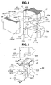
- FIG. 3 is a schematic exploded perspective view showing a seal structure in the portion of FIG. 2 in which a cylinder block, a cylinder head and a front cover meet.
- FIG. 4 is an enlarge view showing the portion of FIG. 3.
- FIG. 5A is a view showing the front cover of FIG. 3 as viewed from an engine block's side.
- FIG. 5B is a sectional view taken across a line F5B-F5B shown in FIG. 5A.
- FIGS. 6A and 6B are views illustrating behavior of liquid gasket into a chamfered portion of the front cover during an assembly operation of the front cover.
- FIGS. 7A and 7B are views illustrating behavior of liquid gasket into recessed portions of the cylinder block and cylinder head during an assembly operation of the front cover.
- FIG. 8 is a schematic perspective view showing a flange of the front cover.
- FIG. 9 is a schematic view showing an engine of another type to which the present invention can be applied.
- FIGS. 10A and 10B are views for illustrating a variation of the arrangement of FIG. 2 in which a projection 30 shown in FIG. 2 is eliminated.
- FIG. 10B shows a comparative example.
- FIG. 1 schematically shows an internal combustion engine 1 having a seal structure according to a first embodiment of the present invention.
- a front side of engine 1 is located on the left side and a rear side is on the right side, as viewed in FIG. 1.
- Engine 1 includes a cylinder block 11 and a cylinder head 12 which is fixedly mounted on the top of cylinder block 11.
- Cylinder block 11 is formed with cylinder bores each receiving a piston 13 forming a combustion chamber between the piston and the cylinder head 12.
- a camshaft 14 is rotatably supported on cylinder head 12.
- a head cover (or rocker cover) 15 is fixed to cylinder head 12 to cover the top of cylinder head 12.
- An upper oil pan 16 is fixed to the bottom of cylinder block 11 through a sealing material such as a liquid gasket.
- a lower oil pan 17 is fixed to the bottom of upper oil pan 16, and arranged to store a lubricating oil for engine 1.
- Cylinder block 11 and upper oil pan 16 form a crankcase in which a crankshaft 18 is supported.
- a front cover 19 is fixed to the front sides of cylinder block 11, cylinder head 12 and upper oil pan 16, and arranged to cover a chain 20 for transmitting rotation from crankshaft 18 to camshaft 14.
- front cover 19 is a single integral (jointless) member. However, it is optional to employ a front cover composed of upper and lower members joined together. Head cover 15 and front cover 19 are designed to protect the inside of the engine such as the inside cavity of cylinder block 11, cylinder head 12, upper oil pan 16 or lower oil pan 17 to close the inside from the outside and to prevent leakage of oil.
- a sealing layer of hardened liquid gasket g is formed for sealing between front cover 19 and an engine block formed by cylinder block 11 and cylinder head 12.
- the sealing layer is formed or filled in a hollow portion defined by one or more recessed portions such as chamfered portion.
- cylinder block 11 serves as a first member (or second member);
- cylinder head 12 serves as a second member (or first member);
- front cover 19 serves as a third member.
- FIG. 2 shows a sealed joint portion A shown in FIG. 1, as viewed from a direction F2 shown in FIG. 4.
- Cylinder head 12 is fixed, through a sheet gasket G, with the top surface of cylinder block 11.
- Front cover 19 is fixed, through liquid gasket g, with the front surfaces of cylinder block 11 and cylinder head 12.
- FIG. 3 schematically shows the sealed joint portion of FIG. 2 in perspective in an exploded form.
- Cylinder block 11 includes a flat top block surface 11a (serving as a first joint surface (or second joint surface)).
- Cylinder head 12 includes a flat head bottom surface 12a (serving as a second joint surface (or first joint surface)).
- Solid sheet gasket G is sandwiched between the flat top surface 11a of cylinder block 11 and the flat bottom surface 12a of cylinder head 12.
- Cylinder block 11 and cylinder head 12 are joined together to form the single engine block, by fastening devices such as bolts 61 (only one is schematically shown), with the horizontally placed sheet gasket G between the cylinder block 11 below and the cylinder head 12 above.
- FIG. 4 schematically shows the ternary sealed joint structure of the three members 11, 12 and 19 in the exploded state in which front cover 19 is broken away.
- Cylinder block 11 includes left and right front block flanges 111 projecting forwards, respectively, from the left front corner and the right front corner of cylinder block 11 shaped like a rectangular parallelepiped.
- Cylinder head 12 includes left and right front head flanges 121 projecting forwards, respectively, from the left front corner and the right front corner of cylinder head 12 shaped like a relatively short rectangular parallelepiped less tall than cylinder block 11.
- Each of block flanges 111 has a flat flange end surface 111a
- each of head flanges 121 has a flat flange end surface 121a.
- the flat flange end surface 111a and the flat flange end surface 121a are vertical and flush with each other so as to serve as third and fourth joint surfaces to be joined with front cover 19.
- each block flange 111 and the flat top surface 11a of cylinder block 11 meet together at a straight front upper edge extending horizontally (in the correct upright position of the engine block, to be exact) from an outer end point to an inner end point of the block flange 111, and these surfaces 111a and 11a form an angle which is substantially equal to 90°.
- a cylinder block recessed portion 113 is formed in an angled corner formed between the vertical flange end surface 111a and the horizontal block top surface 11a in each of the left and right block flanges 111. This recessed portion 113 can be also called beveled portion or cutout portion.
- Cylinder block recessed portion 113 is recessed rearwards so as to increase a spacing from a corresponding cover flange end surface 191a. As shown in FIG. 4, the recessed portion 113 of this example is formed by a sloping surface on the inner side of block flange 111.
- the cylinder block recessed portion 113 of this example is formed on the inner side of each block flange 111 at a position confronting a corresponding recessed portion (or chamfered portion) 1912 formed in front cover 19.
- Each block flange 111 of this example includes a flat outer flange side surface and a flat inner flange side surface which are spaced apart in a widthwise direction W of the flange, that is a lateral direction or left and right direction of cylinder block 11.
- the flat flange end surface 111a is bounded between the outer and inner flange side surfaces.
- the inner flange side surfaces of the left and right front block flanges 111 confront each other whereas the outer flange side surfaces face away from each other.
- the flange side surfaces of the left and right block flanges 111 of this example are parallel to one another, and all extend in a longitudinal direction of cylinder block 11, that is a front and rear direction.
- the recessed portion 113 is in the form of a cutout formed by cutting off the apex formed by the flange end surface 111a, the flange inner side surface and the block top surface 11a.
- recessed portion 113 is defined by the sloping or slant surface sloping down from the block top surface 11a to the inner flange side surface in the widthwise direction W.
- the (widthwise) direction W is perpendicular to the joining direction of the (first and second) joint surfaces (11a and 12a), and perpendicular to a normal to the flange end surface 111a.
- the joining or fastening direction of the joint surfaces 11a and 12a is a direction which is vertical, and perpendicular to the joint surfaces 11a and 12a.
- Bolts 61 extends in this joining direction.
- Each block recessed portion 113 of cylinder block 11 and the corresponding recessed (chamfered) portion 1912 of front cover 19 form a hollow portion therebetween, serving as a collector portion p1 for collecting liquid gasket g, as shown in FIG. 2. Accordingly, it is desirable to determine the shape and dimensions of the cylinder block recessed portion 113 in consideration of a desired quantity of liquid gasket g.
- Cylinder head 12 includes left and right front head flanges 121, and each head flange 121 has a flat flange end surface 121a, like cylinder block 11, as mentioned before.
- the flat flange end surface 121a of each head flange 121 and the flat bottom surface 12a of cylinder head 12 meet together at a straight front lower edge extending horizontally (in the correct upright position of the engine block, to be exact) from an outer end point to an inner end point of the head flange 121, and these surfaces 121a and 12a form an angle which is substantially equal to 90°. As shown in FIGS.
- a cylinder head recessed portion 123 (or beveled or cutout portion) is formed in an angled corner formed between the vertical flange end surface 121a and the horizontal head bottom surface 12a in each of the left and right head flanges 121.
- Cylinder head recessed portion 123 is recessed rearwards so as to increase a spacing from the corresponding cover flange end surface 191a of front cover 19 like the cylinder block recessed portions 113.
- cylinder head recessed portion 123 is in the form of a cutout shaped like a rectangular parallelepiped (or cuboid). However, it is optional to shape each of the cylinder head recessed portions 123 into a form defined by a sloping surface like a mirror image of the cylinder block recessed portion 113 shown in FIG. 4.
- the cylinder head flange 121 is aligned vertically with the block flange 111, and the block flange end surface 111a and head flange end surface 121a are even and flush with each other in the same plane.
- each head flange 121 of this example includes a flat outer flange side surface and a flat inner flange side surface which are spaced apart in the widthwise direction W of the flange, that is the lateral direction of cylinder head 12.
- the flat flange end surface 121a is bounded between the outer and inner flange side surfaces.
- the recessed portion 123 is in the form of a cutout formed by cutting off the apex formed by the flange end surface 121a, the flange inner side surface and the cylinder head bottom surface 12a.
- Head recessed portion 123 is located at a position confronting the corresponding block recessed portion 113 vertically across sheet gasket G.
- Sheet gasket G includes a corner portion G1 projecting into a hollow space formed between the block recessed portion 113 and head recessed portion 123, as shown in FIG. 4.
- the width Wc of the block recessed portion 113 is smaller than or equal to the width We of the cover recessed (chamfered) portion 1912 so as to increase the width of a flat metal touch portion (that is, the parallel overlap portion between a flat metal surface and a flat metal surface) of the flat portion 1911 and flange end surface 111a, and improve the sealing performance.
- the width Wc of the head recessed portion 123 is smaller than or equal to the width We of the cover recessed (chamfered) portion 1912.
- the corner portion G1 of sheet gasket G projects into the space formed by the block recessed portion 113 and the space formed by the head recessed portion 123.
- the projecting corner portion G1 of sheet gasket G does not reach front cover 19.
- the length L2 of the projecting gasket portion G1 is smaller than the depth L1 of recessed portions 113 and 123 which are set equal in the depth measured in the longitudinal direction of the engine block.
- the recessed portions 113 and 123 of cylinder block and head 11 and 12 and recessed portion 1912 of front cover 19 are all formed on the inner side toward an imaginary median plane bisecting the engine block (11 and 12) and the front cover 19 into left and right halves.
- the recessed portion 1912 of front cover 19 extends vertically and forms a vertical hollow portion or zone extending vertically from an upper segment confronting cylinder head 12 to a lower segment confronting cylinder block 11.
- Recessed portions 113 and 123 of cylinder block and head 11 and 12 define a small space or chamber which extends forwards in the longitudinal direction of the engine block, and thereby opens into an intermediate portion of the vertically extending hollow portion formed by the recessed portion 1912 of front cover 19.
- these recessed portions 113, 123 and 1912 are formed on the outer side.
- the collector portion p1 is opened in the left or right outer side surface of the engine block. Accordingly, this arrangement on the outer side can increase the area of the collector portion p1 bared to the outside air, and thereby promote the hardening of liquid gasket g in the collector portion p1.
- the time for hardening liquid gasket g is not problematical (because there is provided means for ensuring the contact with the outside air, for example), it is possible to form the recessed portions 113 and 123 in an intermediate position in the flange widthwise direction W between the outer and inner flange side surfaces.
- Front cover 19 of this example has a U-shaped cross section like a channel bar, and includes a plate-like main portion and left and right cover flanges 191 projecting rearwards toward the engine block, respectively, from the left and right ends of the main portion.
- Each cover flange 191 has a flange end surface 191a (serving as a fifth joint surface), and outer and inner flange side surfaces which are flat and parallel to each other in this example and which terminate at respective rear ends between which the flange end surface 191a extends in the flange widthwise direction.
- Front cover 19 is joined to the engine block composed of cylinder block 11 and cylinder head 12 by fastening devices such as bolts 62 (only one is shown schematically in FIG. 1) through liquid gasket g.
- each cover flange 191 is connected end to end with the corresponding block flange 111 and head flange 121.
- the liquid gasket g is interposed between the cover flange end surface 191a, and the flange end surfaces 111a and 121a of cylinder flange 111 and head flange 121.
- FIG. 5A shows front cover 19 as viewed from the rear side or the engine block's side.
- FIG. 5B is a sectional view taken across a line 5B-5B shown in FIG. 5A.
- the projecting end of each cover flange 191 is chamfered, and the flange end surface 191a of each cover flange 191 includes a flat region or portion 1911 and the above-mentioned recessed or chamfered portion 1912 extending side by side vertically.
- Flat portion 1911 confronts the corresponding flat flange end surfaces of block flange 111 and head flange 121.
- the vertical direction and the lateral direction of the engine block are parallel to the flat portion 1911.
- the longitudinal direction of the engine block is perpendicular to the flat portion 1911.
- each cover flange 191 is located on the outer side and bounded by the outer flange side surface.
- Flat portion 1911 extends from the outer end of cover flange 191 toward the inner end.
- Flat portion 1911 has a width Wf as shown in FIG. 5A.
- Recessed portion 1912 is located on the inner side of the cover flange between the flat portion 1911 and the flange inner side surface facing toward the flange inner side surface on the opposite side across an imaginary median plane bisecting front cover 19 into left and right halves.
- recessed portion 1912 is defined by a sloping or slant flat surface sloping from the inner end of the flat portion 1911, to the flange inner side surface so that the spacing from the flange end surfaces 111a and 121a of the corresponding block and cylinder flanges 111 and 121 increases gradually toward the flange inner side surface of the cover flange 1911.
- a flat step surface 1913 extends between the inner end of the flat portion 1911 and the outer end of the sloping surface, in the longitudinal direction of the engine block or in parallel to the outer and inner flange side surfaces.
- each cover flange 191 extends vertically and forms a vertically extending collector portion p2 in which the liquid gasket g is collected.
- This collector portion p2 is formed between the recessed portion 1912 of each cover flange 191 and the flat flange end surfaces of the corresponding block flange 111 and head flange 121.
- the step surface 1913 may be inclined so that the angle between the flat portion 1911 and the flat step surface 1913 is equal to an obtuse angle, and that the inclination of the step surface 1913 is sharper than the inclination of the sloping surface, and the step surface 1913 forms a concave angle with the sloping surface. However, it is preferable to orient the step surface so that the step surface is perpendicular to the flat portion 111.
- FIG. 8 schematically shows one cover flange 1911.
- cover flange 1911 includes a projecting portion 30 projecting from the sloping surface of the recessed portion 1912, rearwards toward the space formed by the block recessed portion 113 and head recessed portion 123 of the corresponding block and head flanges 111 and 121.
- the projecting portion 30 includes a flat end surface which is even, flush and continuous with the flat portion 1911 in the example shown in FIG. 8.
- the flat portion 1911 projects in the form of the projecting portion 30 to the flange inner side surface, and the vertically extending recessed portion 1912 is discontinued and divided by the projecting portion 30, into an upper recessed segment extending upwards from projecting portion 30 and a lower recessed segment extending downwards from projecting portion 30.
- the sheet gasket G of this example includes a bead 32 in the form of a ridge or projection, extending in the longitudinal direction between the corresponding block flange 111 and head flange 121, and thereby forms a seal line alongside the outer flange side surfaces of block flange 111 and head flange 121.
- This bead 32 extends straight toward the flat portion 1911 of the corresponding cover flange 191 so that the longitudinal direction of the bead 32 intersects the flat portion 1911 at right angles.
- the length or height L3 of projecting portion 30 is shorter than the length or height L4 of the space formed by the block and head recessed portions 113 and 123.
- FIGS. 6A, 6B, 7A and 7B illustrate the liquid gasket g in the assembly process of the cylinder block 11, cylinder head 12 and front cover 19.
- FIGS. 6A and 6B show behavior of liquid gasket g between one cover flange end surface 191a and the corresponding block flange end surface 111a (or head flange end surface 121a) in the form of a cross section as viewed from above.
- FIGS. 7A and 7B show behavior of liquid gasket g between one cover flange end surface 191a and the corresponding block and head recessed portions 113 and 123 (in the joint portion A).
- liquid gasket g which is not yet hard is applied to the inner end portion of flat portion 1911 of cover flange 191 adjacent to the step surface 1913.
- the step surface 1913 can serve as a target or reference position in an operation of applying liquid gasket g, and thereby make it easier to apply liquid gasket g at a correct position.
- the flange end surface 191a of cover flange 1901 and the flange end surfaces 111a and 121a of the corresponding block flange 111 and head flange 121 are moved toward each other gradually, and attached to each other, and the cover flange 191 and the block and head flanges 111 and 121 are fastened end to end by bolts 61.
- liquid gasket g is pressed between the confronting flange end surfaces, and spread in the collector portion p2 so that the liquid gasket g fills the interspace between the confronting flange end surfaces, as shown in FIGS. 6B and 7B.
- the liquid gasket g forms a layer between the flat flange end surfaces of front cover 19 and the engine block. Moreover, the liquid gasket g is readily collected in a larger quantity in the collector portions p1 and p2. The collector portion p1 is connected with collector portion p2 through gaps 31, so that liquid gasket g can flow therebetween smoothly.
- the portion G1 of the sheet gasket G projects in the space formed between block recessed portion 113 and head recessed portion 123, and the projecting portion 30 projects toward the projection G1 of sheet gasket G to the extent not preventing smooth flow of liquid gasket g up and down through the gap formed between the projecting portion 30 and the sheet gasket G. Accordingly, the liquid gasket g can be readily filled on both sides of the projecting portion G1 of sheet gasket G.
- the liquid gasket g is made hard by leaving for a predetermined time interval for drying.
- the hardened liquid gasket g forms a gasket layer including a thin film layer g1 formed between the flat portion 1911 of each cover flange 191 and the flat flange end surfaces 111a and 121a of block flange 111 and head flanges 121; and swell portions g2 and g3 formed, respectively, in collector portions p1 and p2, and connected continuously with the thin film layer g1.
- the swell portion g3 bulges like a ridge and extending vertically in the chamfered portion 1912.
- the chamfered portion 1912 is formed only on one side along one side edge of the fifth joint surface in the form of the flange end surface 191a, alongside the flat portion 1911. Accordingly, the chamfered portion on each side defines the liquid gasket collector portion p2, and thereby makes it possible to reduce the required time for drying the liquid gasket g by exposing the soft liquid gasket to the outside air.
- the swell portions g2 and g3 are formed only on one side. Accordingly, the liquid gasket can improve the withstanding strength and the sealing performance between cylinder block 11 and front cover 19 and between cylinder head 12 and front cover 19.
- the seal member produced by the hardened liquid gasket can be shaped so as to eliminate an angled corner liable to suffer stress concentration.
- the swell portions g2 and g3 are formed at a position at which stress concentration tends to occur. Therefore, the swell portions can function to disperse stress concentration therein, and thereby improve the durability specifically against damage such as cracking, and the sealing performance of the seal or gasket.
- Recessed portions 113 and 123 are formed at a T-shaped junction between the joint interface between cylinder block 11 and cylinder 12, and the joint interface between front cover 19 and the engine block which is a subassembly of cylinder block 11 and cylinder head 12.
- the thus-formed recessed portions 113 and 123 make it easier to fill the space at the T-shaped junction with the liquid gasket g smoothly, and to make the swell portions of the liquid gasket filled up in the collector portions p1 and p2.
- Recessed portions 113 and 123 are formed on the same side as the chamfered portion 1912 in the widthwise direction W, and arranged to confront the chamfered portion 1912. Accordingly, the widthwise dimension of the surface contact area between the flat region 1911 of front cover 19 and the flat flange end surfaces 111a and 121a of cylinder block 11 and cylinder head 12 is increased as compared to the arrangement in which recessed portions 113 and 123 are formed on the other side away from chamfered portion 1912. Therefore, the sealing effect is improved.
- Part of the sheet gasket G is designed to project into the space formed in recessed portions 113 and 123. Therefore, the liquid gasket g and sheet gasket G are lapped reliably. The projecting end portion of sheet gasket G is inserted and buried in the hardened liquid gasket g. Therefore, sheet gasket G and liquid gasket g are securely united into a T-shaped seal member which can improve the sealing performance significantly.
- Chamfered portion 1912 and recessed portions 113 and 123 are formed on the inner side in the widthwise direction W, that is on the inner side with respect to a leaking direction F1 of lubricating oil as shown in FIG. 4. Therefore, the seal member on the inner side can prevent the leakage of oil more reliably as compared to the arrangement having a liquid gasket portion on the outer side of the leaking direction. Moreover, the arrangement having the chamfered and recess portions on the inner side can prevent the liquid gasket from protruding outsides or dropping.
- the step surface 1913 is formed between the flat region 1911 and the sloping surface. This step surface 1913 makes it easier to produce the flat region and the sloping surface accurately to meet the respective requirements of the accuracy without interference from each other. Therefore, it is possible to decrease the product by product nonuniformity, and to produce the seal structure accurately and reliably.
- the projecting portion or projection 30 projects toward the recessed portions 113 and 123. Therefore, the liquid gasket g can readily flow, from below and from above as shown by arrows in FIG. 7B, into recessed portion 113 and into recessed portion 123. Moreover, the sloping surface can serve as a guide for leading the liquid gasket g into the deepest portion of the recessed portion. Therefore, the projecting end portion G1 of sheet gasket G can be tightly enclosed and buried in the liquid gasket on both sides of sheet gasket G.
- Projection 30 has the flat end surface flush with the flat portion 1911. Accordingly, projection 30 increases the width of the flat joint surface partly. Thereby, projection 30 can support the pressure efficiently during the joining operation, and prevent undesired flow of the not-yet-hardened liquid gasket g.
- Chamfered portion 1912 and recessed portions 113 and 123 are formed on the same side in the widthwise direction W. This arrangement makes it easier to set the bead 32 of sheet gasket G at the correct position confronting the flat portion 1911 without the need for further increasing the width of the contact area.
- the present invention is not limited to the embodiment illustrated and described above. Various modifications and variations are possible within the scope of the present invention.
- the three main members of the seal structure are cylinder block 11, cylinder head 12 and front cover 19.
- the seal structure according to the present invention may be a structure shown at B in FIG. 1 including, as the main three members, cylinder block 11, upper oil pan 16 and front cover 19; or may be a structure shown at C in FIG. 1 including, as the three main member, cylinder block 11, upper oil pan 16 and a rear oil seal retainer 21.
- Rear oil seal retainer 21 is a member for supporting, fixedly on the engine 1, an oil seal for sealing the inside of the crankcase from the outside.
- engine 1 may be of a type shown in FIG. 9.
- a cylinder head 12 is fixed to the top of a front cover 19, as well as to the top of a cylinder block 11.
- the seal structure according to the present invention can be applied to any one or more of a D portion, an E portion and an F portion of the engine shown in FIG. 9.
- chamfered portion 1912 extends plainly without being discontinued by the projection 30.
- the sealing effect is improved because liquid gasket g can flow smoothly on both sides of sheet gasket G by the aid of the recessed portions (113, 123), by contrast to a comparative example shown in FIG. 10B having no recessed portions.
- Sheet gasket G between cylinder block 11 and cylinder head 12 may be replaced by a layer of liquid gasket g.
- liquid gasket g is pressed between the cylinder block top surface 11a and the cylinder head bottom surface 12a, and introduced into the collector portion p1 smoothly.
- recessed portion 113 or 123 is formed in each of the block flange 111 and head flange 121. However, it is optional to employ an arrangement in which a recessed portion 113 or 123 is formed only in either of the block flange 111 and head flange 121.
- the seal structure according to the present invention can be applied to various machines and structures, specifically to oil seal portions, as well as to engines.
Landscapes
- Engineering & Computer Science (AREA)
- General Engineering & Computer Science (AREA)
- Mechanical Engineering (AREA)
- Physics & Mathematics (AREA)
- Geometry (AREA)
- Gasket Seals (AREA)
Abstract
Description
- The present invention relates to a seal structure. In particular, the present invention relates to a seal structure of three or more members joined together with the interposition of seal layer such as a layer of liquid gasket.
- Published
Japanese Patent Application Publication No. H11(1999)-173424 - However, the seal structure of the above-mentioned Japanese patent document tends to be insufficient in strength against a relative displacement (specifically in a shearing direction) between the flanges because the liquid gasket is dispersed into two portions for accumulating or collecting the liquid gasket.
- The inventor of the present application has proposed a seal structure designed to reduce the hardening time of liquid gasket between two members, and to improve the sealing performance with a smaller amount of the liquid gasket (
EP 1 522 769A1 published on April 13, 2005JP 2005-114113A published on April 28, 2005 - It is an object of the present invention to provide a seal structure to improve sealing properties especially for a joint portion at which three members are joined together.
- According to one aspect of the invention, a seal structure comprises: a first member including a first joint surface and a flat third joint surface forming a corner with the first joint surface; a second member joined with the first member, the second member including a second joint surface joined with the first joint surface of the first member, a flat fourth joint surface forming a corner with the second joint surface, and a recessed portion formed in the corner between the second and fourth joint surfaces; and a third member joined with the first and second members, the third member including a fifth joint surface joined, through a liquid seal, with the flat third joint surface of the first member and the flat fourth joint surface of the second member, the fifth joint surface including a flat region and a chamfered region which is recessed from the flat region of the fifth joint surface and which confronts the recessed portion of the second member.
- According to another aspect of the present invention, a seal structure comprises: a first member including a flat first joint surface and a flat third joint surface; a second member joined with the first member, the second member including a flat second joint surface joined with the first joint surface of the first member, and a flat fourth joint surface; a third member joined with the first and second members, the third member including a flat fifth joint surface which extends along the third joint surface and the fourth joint surface of the first and second members, and which is joined with the third and fourth joint surfaces of the first and second members; and a seal member. The seal member includes: a first seal section which is interposed between the first and second joint surfaces of the first and second members; a second seal section extending along the fifth joint surface and including a first segment interposed between the fifth joint surface and the third joint surface of the first member, a second segment interposed between the fifth joint surfaced and the fourth joint surface of the second member, and an intermediate portion located between the first and second segments; and a third seal section bulging from the intermediate portion of the second seal section, and connecting with the first seal section.
- FIG. 1 is a schematic view showing an engine including a seal structure according to one embodiment of the present invention.
- FIG. 2 is a view of a portion A of the engine shown in FIG. 1, as viewed from a direction F2 shown in FIG. 4.
- FIG. 3 is a schematic exploded perspective view showing a seal structure in the portion of FIG. 2 in which a cylinder block, a cylinder head and a front cover meet.
- FIG. 4 is an enlarge view showing the portion of FIG. 3.
- FIG. 5A is a view showing the front cover of FIG. 3 as viewed from an engine block's side. FIG. 5B is a sectional view taken across a line F5B-F5B shown in FIG. 5A.
- FIGS. 6A and 6B are views illustrating behavior of liquid gasket into a chamfered portion of the front cover during an assembly operation of the front cover.
- FIGS. 7A and 7B are views illustrating behavior of liquid gasket into recessed portions of the cylinder block and cylinder head during an assembly operation of the front cover.
- FIG. 8 is a schematic perspective view showing a flange of the front cover.
- FIG. 9 is a schematic view showing an engine of another type to which the present invention can be applied.
- FIGS. 10A and 10B are views for illustrating a variation of the arrangement of FIG. 2 in which a
projection 30 shown in FIG. 2 is eliminated. FIG. 10B shows a comparative example. - FIG. 1 schematically shows an
internal combustion engine 1 having a seal structure according to a first embodiment of the present invention. In this example, a front side ofengine 1 is located on the left side and a rear side is on the right side, as viewed in FIG. 1. -
Engine 1 includes acylinder block 11 and acylinder head 12 which is fixedly mounted on the top ofcylinder block 11.Cylinder block 11 is formed with cylinder bores each receiving apiston 13 forming a combustion chamber between the piston and thecylinder head 12. A camshaft 14 is rotatably supported oncylinder head 12. A head cover (or rocker cover) 15 is fixed tocylinder head 12 to cover the top ofcylinder head 12. Anupper oil pan 16 is fixed to the bottom ofcylinder block 11 through a sealing material such as a liquid gasket. Alower oil pan 17 is fixed to the bottom ofupper oil pan 16, and arranged to store a lubricating oil forengine 1.Cylinder block 11 andupper oil pan 16 form a crankcase in which acrankshaft 18 is supported. - A
front cover 19 is fixed to the front sides ofcylinder block 11,cylinder head 12 andupper oil pan 16, and arranged to cover achain 20 for transmitting rotation fromcrankshaft 18 to camshaft 14. In this example,front cover 19 is a single integral (jointless) member. However, it is optional to employ a front cover composed of upper and lower members joined together.Head cover 15 andfront cover 19 are designed to protect the inside of the engine such as the inside cavity ofcylinder block 11,cylinder head 12,upper oil pan 16 orlower oil pan 17 to close the inside from the outside and to prevent leakage of oil. - A sealing layer of hardened liquid gasket g is formed for sealing between
front cover 19 and an engine block formed bycylinder block 11 andcylinder head 12. The sealing layer is formed or filled in a hollow portion defined by one or more recessed portions such as chamfered portion. In this example,cylinder block 11 serves as a first member (or second member);cylinder head 12 serves as a second member (or first member); andfront cover 19 serves as a third member. - FIG. 2 shows a sealed joint portion A shown in FIG. 1, as viewed from a direction F2 shown in FIG. 4.
Cylinder head 12 is fixed, through a sheet gasket G, with the top surface ofcylinder block 11.Front cover 19 is fixed, through liquid gasket g, with the front surfaces ofcylinder block 11 andcylinder head 12. - FIG. 3 schematically shows the sealed joint portion of FIG. 2 in perspective in an exploded form.
Cylinder block 11 includes a flattop block surface 11a (serving as a first joint surface (or second joint surface)).Cylinder head 12 includes a flathead bottom surface 12a (serving as a second joint surface (or first joint surface)). Solid sheet gasket G is sandwiched between theflat top surface 11a ofcylinder block 11 and theflat bottom surface 12a ofcylinder head 12.Cylinder block 11 andcylinder head 12 are joined together to form the single engine block, by fastening devices such as bolts 61 (only one is schematically shown), with the horizontally placed sheet gasket G between thecylinder block 11 below and thecylinder head 12 above. j0017 - FIG. 4 schematically shows the ternary sealed joint structure of the three
members front cover 19 is broken away.Cylinder block 11 includes left and rightfront block flanges 111 projecting forwards, respectively, from the left front corner and the right front corner ofcylinder block 11 shaped like a rectangular parallelepiped.Cylinder head 12 includes left and rightfront head flanges 121 projecting forwards, respectively, from the left front corner and the right front corner ofcylinder head 12 shaped like a relatively short rectangular parallelepiped less tall thancylinder block 11. Each ofblock flanges 111 has a flatflange end surface 111a, and each ofhead flanges 121 has a flatflange end surface 121a. On each of the left and right sides, the flatflange end surface 111a and the flatflange end surface 121a are vertical and flush with each other so as to serve as third and fourth joint surfaces to be joined withfront cover 19. - The flat
flange end surface 111a of eachblock flange 111 and theflat top surface 11a ofcylinder block 11 meet together at a straight front upper edge extending horizontally (in the correct upright position of the engine block, to be exact) from an outer end point to an inner end point of theblock flange 111, and thesesurfaces portion 113 is formed in an angled corner formed between the verticalflange end surface 111a and the horizontal blocktop surface 11a in each of the left andright block flanges 111. This recessedportion 113 can be also called beveled portion or cutout portion. Cylinder block recessedportion 113 is recessed rearwards so as to increase a spacing from a corresponding cover flangeend surface 191a. As shown in FIG. 4, the recessedportion 113 of this example is formed by a sloping surface on the inner side ofblock flange 111. - The cylinder block recessed
portion 113 of this example is formed on the inner side of eachblock flange 111 at a position confronting a corresponding recessed portion (or chamfered portion) 1912 formed infront cover 19. Eachblock flange 111 of this example includes a flat outer flange side surface and a flat inner flange side surface which are spaced apart in a widthwise direction W of the flange, that is a lateral direction or left and right direction ofcylinder block 11. The flatflange end surface 111a is bounded between the outer and inner flange side surfaces. The inner flange side surfaces of the left and rightfront block flanges 111 confront each other whereas the outer flange side surfaces face away from each other. The flange side surfaces of the left andright block flanges 111 of this example are parallel to one another, and all extend in a longitudinal direction ofcylinder block 11, that is a front and rear direction. In eachblock flange 111, the recessedportion 113 is in the form of a cutout formed by cutting off the apex formed by theflange end surface 111a, the flange inner side surface and the blocktop surface 11a. In this example, as shown in FIG. 4, recessedportion 113 is defined by the sloping or slant surface sloping down from the blocktop surface 11a to the inner flange side surface in the widthwise direction W. The (widthwise) direction W is perpendicular to the joining direction of the (first and second) joint surfaces (11a and 12a), and perpendicular to a normal to theflange end surface 111a. The joining or fastening direction of thejoint surfaces joint surfaces Bolts 61 extends in this joining direction. Each block recessedportion 113 ofcylinder block 11 and the corresponding recessed (chamfered)portion 1912 offront cover 19 form a hollow portion therebetween, serving as a collector portion p1 for collecting liquid gasket g, as shown in FIG. 2. Accordingly, it is desirable to determine the shape and dimensions of the cylinder block recessedportion 113 in consideration of a desired quantity of liquid gasket g. -
Cylinder head 12 includes left and rightfront head flanges 121, and eachhead flange 121 has a flatflange end surface 121a, likecylinder block 11, as mentioned before. The flatflange end surface 121a of eachhead flange 121 and theflat bottom surface 12a ofcylinder head 12 meet together at a straight front lower edge extending horizontally (in the correct upright position of the engine block, to be exact) from an outer end point to an inner end point of thehead flange 121, and thesesurfaces flange end surface 121a and the horizontalhead bottom surface 12a in each of the left andright head flanges 121. Cylinder head recessedportion 123 is recessed rearwards so as to increase a spacing from the corresponding cover flangeend surface 191a offront cover 19 like the cylinder block recessedportions 113. As shown in FIG. 4. cylinder head recessedportion 123 is in the form of a cutout shaped like a rectangular parallelepiped (or cuboid). However, it is optional to shape each of the cylinder head recessedportions 123 into a form defined by a sloping surface like a mirror image of the cylinder block recessedportion 113 shown in FIG. 4. - In the assembled state, on each of the left and right sides, the
cylinder head flange 121 is aligned vertically with theblock flange 111, and the blockflange end surface 111a and headflange end surface 121a are even and flush with each other in the same plane. - The cylinder head recessed
portion 123 of this example is formed on the inner side of eachhead flange 121 at a position confronting the corresponding recessed portion (or chamfered portion) 1912 formed infront cover 19. Like theblock flanges 111, eachhead flange 121 of this example includes a flat outer flange side surface and a flat inner flange side surface which are spaced apart in the widthwise direction W of the flange, that is the lateral direction ofcylinder head 12. The flatflange end surface 121a is bounded between the outer and inner flange side surfaces. The recessedportion 123 is in the form of a cutout formed by cutting off the apex formed by theflange end surface 121a, the flange inner side surface and the cylinderhead bottom surface 12a. - Head recessed
portion 123 is located at a position confronting the corresponding block recessedportion 113 vertically across sheet gasket G. Sheet gasket G includes a corner portion G1 projecting into a hollow space formed between the block recessedportion 113 and head recessedportion 123, as shown in FIG. 4. In this example, the width Wc of the block recessedportion 113 is smaller than or equal to the width We of the cover recessed (chamfered)portion 1912 so as to increase the width of a flat metal touch portion (that is, the parallel overlap portion between a flat metal surface and a flat metal surface) of theflat portion 1911 andflange end surface 111a, and improve the sealing performance. Similarly, the width Wc of the head recessedportion 123 is smaller than or equal to the width We of the cover recessed (chamfered)portion 1912. The corner portion G1 of sheet gasket G projects into the space formed by the block recessedportion 113 and the space formed by the head recessedportion 123. However, the projecting corner portion G1 of sheet gasket G does not reachfront cover 19. As shown in FIG. 2, in this example, the length L2 of the projecting gasket portion G1 is smaller than the depth L1 of recessedportions - On each of the left and right sides, the recessed
portions head portion 1912 offront cover 19 are all formed on the inner side toward an imaginary median plane bisecting the engine block (11 and 12) and thefront cover 19 into left and right halves. The recessedportion 1912 offront cover 19 extends vertically and forms a vertical hollow portion or zone extending vertically from an upper segment confrontingcylinder head 12 to a lower segment confrontingcylinder block 11. Recessedportions head portion 1912 offront cover 19. - However, it is optional to form these recessed
portions portions -
Front cover 19 of this example has a U-shaped cross section like a channel bar, and includes a plate-like main portion and left andright cover flanges 191 projecting rearwards toward the engine block, respectively, from the left and right ends of the main portion. Eachcover flange 191 has aflange end surface 191a (serving as a fifth joint surface), and outer and inner flange side surfaces which are flat and parallel to each other in this example and which terminate at respective rear ends between which theflange end surface 191a extends in the flange widthwise direction.Front cover 19 is joined to the engine block composed ofcylinder block 11 andcylinder head 12 by fastening devices such as bolts 62 (only one is shown schematically in FIG. 1) through liquid gasket g. In the assembled state, eachcover flange 191 is connected end to end with thecorresponding block flange 111 andhead flange 121. The liquid gasket g is interposed between the coverflange end surface 191a, and theflange end surfaces cylinder flange 111 andhead flange 121. - FIG. 5A shows
front cover 19 as viewed from the rear side or the engine block's side. FIG. 5B is a sectional view taken across a line 5B-5B shown in FIG. 5A. As shown in these figures, the projecting end of eachcover flange 191 is chamfered, and theflange end surface 191a of eachcover flange 191 includes a flat region orportion 1911 and the above-mentioned recessed or chamferedportion 1912 extending side by side vertically.Flat portion 1911 confronts the corresponding flat flange end surfaces ofblock flange 111 andhead flange 121. The vertical direction and the lateral direction of the engine block are parallel to theflat portion 1911. The longitudinal direction of the engine block is perpendicular to theflat portion 1911. In this example, theflat portion 1911 of eachcover flange 191 is located on the outer side and bounded by the outer flange side surface.Flat portion 1911 extends from the outer end ofcover flange 191 toward the inner end.Flat portion 1911 has a width Wf as shown in FIG. 5A.
Recessedportion 1912 is located on the inner side of the cover flange between theflat portion 1911 and the flange inner side surface facing toward the flange inner side surface on the opposite side across an imaginary median plane bisectingfront cover 19 into left and right halves. In this example, recessedportion 1912 is defined by a sloping or slant flat surface sloping from the inner end of theflat portion 1911, to the flange inner side surface so that the spacing from theflange end surfaces cylinder flanges cover flange 1911. Aflat step surface 1913 extends between the inner end of theflat portion 1911 and the outer end of the sloping surface, in the longitudinal direction of the engine block or in parallel to the outer and inner flange side surfaces. The thus-shaped recessed or chamferedportion 1912 of eachcover flange 191 extends vertically and forms a vertically extending collector portion p2 in which the liquid gasket g is collected. This collector portion p2 is formed between the recessedportion 1912 of eachcover flange 191 and the flat flange end surfaces of thecorresponding block flange 111 andhead flange 121. Thestep surface 1913 may be inclined so that the angle between theflat portion 1911 and theflat step surface 1913 is equal to an obtuse angle, and that the inclination of thestep surface 1913 is sharper than the inclination of the sloping surface, and thestep surface 1913 forms a concave angle with the sloping surface. However, it is preferable to orient the step surface so that the step surface is perpendicular to theflat portion 111. - FIG. 8 schematically shows one
cover flange 1911. As shown in FIG. 8 and FIG. 2,cover flange 1911 includes a projectingportion 30 projecting from the sloping surface of the recessedportion 1912, rearwards toward the space formed by the block recessedportion 113 and head recessedportion 123 of the corresponding block andhead flanges portion 30 includes a flat end surface which is even, flush and continuous with theflat portion 1911 in the example shown in FIG. 8. In other words, theflat portion 1911 projects in the form of the projectingportion 30 to the flange inner side surface, and the vertically extending recessedportion 1912 is discontinued and divided by the projectingportion 30, into an upper recessed segment extending upwards from projectingportion 30 and a lower recessed segment extending downwards from projectingportion 30. The sheet gasket G of this example includes abead 32 in the form of a ridge or projection, extending in the longitudinal direction between thecorresponding block flange 111 andhead flange 121, and thereby forms a seal line alongside the outer flange side surfaces ofblock flange 111 andhead flange 121. Thisbead 32 extends straight toward theflat portion 1911 of thecorresponding cover flange 191 so that the longitudinal direction of thebead 32 intersects theflat portion 1911 at right angles. - In the assembled state shown in FIG. 2, there is formed an
upper gap 31 through which the collector portion p1 formed by the block recessedportion 113 and head recessedportion 123 is connected with the upper segment of the collector portion p2 formed between the cover recessedportion 1912 and theflange end surface 121a above the projectingportion 30, and alower gap 31 through which the collector portion p1 is connected with the lower segment of the collector portion p2 formed between the cover recessedportion 1912 and the blockflange end surface 111a below the projectingportion 30. Accordingly, the length or height L3 of projectingportion 30 is shorter than the length or height L4 of the space formed by the block and head recessedportions - FIGS. 6A, 6B, 7A and 7B illustrate the liquid gasket g in the assembly process of the
cylinder block 11,cylinder head 12 andfront cover 19. FIGS. 6A and 6B show behavior of liquid gasket g between one coverflange end surface 191a and the corresponding blockflange end surface 111a (or headflange end surface 121a) in the form of a cross section as viewed from above. FIGS. 7A and 7B show behavior of liquid gasket g between one coverflange end surface 191a and the corresponding block and head recessedportions 113 and 123 (in the joint portion A). - As shown in FIGS. 6A and 7B, liquid gasket g which is not yet hard is applied to the inner end portion of
flat portion 1911 ofcover flange 191 adjacent to thestep surface 1913. In this case, thestep surface 1913 can serve as a target or reference position in an operation of applying liquid gasket g, and thereby make it easier to apply liquid gasket g at a correct position. Then, theflange end surface 191a of cover flange 1901 and theflange end surfaces corresponding block flange 111 andhead flange 121 are moved toward each other gradually, and attached to each other, and thecover flange 191 and the block andhead flanges bolts 61. During this, the liquid gasket g is pressed between the confronting flange end surfaces, and spread in the collector portion p2 so that the liquid gasket g fills the interspace between the confronting flange end surfaces, as shown in FIGS. 6B and 7B. - As shown in FIGS. 6B and 7B, the liquid gasket g forms a layer between the flat flange end surfaces of
front cover 19 and the engine block. Moreover, the liquid gasket g is readily collected in a larger quantity in the collector portions p1 and p2. The collector portion p1 is connected with collector portion p2 throughgaps 31, so that liquid gasket g can flow therebetween smoothly. - In the example shown in FIG. 2, the portion G1 of the sheet gasket G projects in the space formed between block recessed
portion 113 and head recessedportion 123, and the projectingportion 30 projects toward the projection G1 of sheet gasket G to the extent not preventing smooth flow of liquid gasket g up and down through the gap formed between the projectingportion 30 and the sheet gasket G. Accordingly, the liquid gasket g can be readily filled on both sides of the projecting portion G1 of sheet gasket G. - After the fastening operation, the liquid gasket g is made hard by leaving for a predetermined time interval for drying. The hardened liquid gasket g forms a gasket layer including a thin film layer g1 formed between the
flat portion 1911 of eachcover flange 191 and the flatflange end surfaces block flange 111 andhead flanges 121; and swell portions g2 and g3 formed, respectively, in collector portions p1 and p2, and connected continuously with the thin film layer g1. The swell portion g3 bulges like a ridge and extending vertically in the chamferedportion 1912. - In the thus-constructed structure, the chamfered
portion 1912 is formed only on one side along one side edge of the fifth joint surface in the form of theflange end surface 191a, alongside theflat portion 1911. Accordingly, the chamfered portion on each side defines the liquid gasket collector portion p2, and thereby makes it possible to reduce the required time for drying the liquid gasket g by exposing the soft liquid gasket to the outside air. The swell portions g2 and g3 are formed only on one side. Accordingly, the liquid gasket can improve the withstanding strength and the sealing performance betweencylinder block 11 andfront cover 19 and betweencylinder head 12 andfront cover 19. - Stress (tensile stress and shearing stress) is produced in the liquid gasket g when
front cover 19 andcylinder block 11 are shifted relative to each other orfront cover 19 andcylinder head 12 are shifted relative to each other. The seal member produced by the hardened liquid gasket can be shaped so as to eliminate an angled corner liable to suffer stress concentration. Moreover, the swell portions g2 and g3 are formed at a position at which stress concentration tends to occur. Therefore, the swell portions can function to disperse stress concentration therein, and thereby improve the durability specifically against damage such as cracking, and the sealing performance of the seal or gasket. - Recessed
portions cylinder block 11 andcylinder 12, and the joint interface betweenfront cover 19 and the engine block which is a subassembly ofcylinder block 11 andcylinder head 12. The thus-formed recessedportions - Recessed
portions portion 1912 in the widthwise direction W, and arranged to confront the chamferedportion 1912. Accordingly, the widthwise dimension of the surface contact area between theflat region 1911 offront cover 19 and the flatflange end surfaces cylinder block 11 andcylinder head 12 is increased as compared to the arrangement in which recessedportions chamfered portion 1912. Therefore, the sealing effect is improved. - Part of the sheet gasket G is designed to project into the space formed in recessed
portions -
Chamfered portion 1912 and recessedportions - In
flange end surface 191a of eachcover flange 1911, thestep surface 1913 is formed between theflat region 1911 and the sloping surface. Thisstep surface 1913 makes it easier to produce the flat region and the sloping surface accurately to meet the respective requirements of the accuracy without interference from each other. Therefore, it is possible to decrease the product by product nonuniformity, and to produce the seal structure accurately and reliably. - The projecting portion or
projection 30 projects toward the recessedportions portion 113 and into recessedportion 123. Moreover, the sloping surface can serve as a guide for leading the liquid gasket g into the deepest portion of the recessed portion. Therefore, the projecting end portion G1 of sheet gasket G can be tightly enclosed and buried in the liquid gasket on both sides of sheet gasket G. -
Projection 30 has the flat end surface flush with theflat portion 1911. Accordingly,projection 30 increases the width of the flat joint surface partly. Thereby,projection 30 can support the pressure efficiently during the joining operation, and prevent undesired flow of the not-yet-hardened liquid gasket g. -
Chamfered portion 1912 and recessedportions bead 32 of sheet gasket G at the correct position confronting theflat portion 1911 without the need for further increasing the width of the contact area. - The present invention is not limited to the embodiment illustrated and described above. Various modifications and variations are possible within the scope of the present invention. In the preceding embodiment, the three main members of the seal structure (at A shown in FIG. 1) are
cylinder block 11,cylinder head 12 andfront cover 19. However, the seal structure according to the present invention may be a structure shown at B in FIG. 1 including, as the main three members,cylinder block 11,upper oil pan 16 andfront cover 19; or may be a structure shown at C in FIG. 1 including, as the three main member,cylinder block 11,upper oil pan 16 and a rearoil seal retainer 21. Rearoil seal retainer 21 is a member for supporting, fixedly on theengine 1, an oil seal for sealing the inside of the crankcase from the outside. - Moreover,
engine 1 may be of a type shown in FIG. 9. In the engine shown in FIG. 9, acylinder head 12 is fixed to the top of afront cover 19, as well as to the top of acylinder block 11. The seal structure according to the present invention can be applied to any one or more of a D portion, an E portion and an F portion of the engine shown in FIG. 9. - As shown in FIG. 10A, it is optional to eliminate the projecting portion 30 (shown in FIG. 2). In this case, chamfered
portion 1912 extends plainly without being discontinued by theprojection 30. In this case, too, the sealing effect is improved because liquid gasket g can flow smoothly on both sides of sheet gasket G by the aid of the recessed portions (113, 123), by contrast to a comparative example shown in FIG. 10B having no recessed portions. - Sheet gasket G between
cylinder block 11 andcylinder head 12 may be replaced by a layer of liquid gasket g. In this case, liquid gasket g is pressed between the cylinder blocktop surface 11a and the cylinderhead bottom surface 12a, and introduced into the collector portion p1 smoothly. - In the illustrated embodiment, recessed
portion block flange 111 andhead flange 121. However, it is optional to employ an arrangement in which a recessedportion block flange 111 andhead flange 121. - The seal structure according to the present invention can be applied to various machines and structures, specifically to oil seal portions, as well as to engines.
- In this specification, geometrical terms such as flat, parallel, perpendicular, vertical or horizontal are used to contain a meaning of "exactly or approximately". For example, "flat" means "exactly or approximately flat" or "substantially flat".
- This application is based on a prior
Japanese Patent Application No. 2005-65350 filed on March 9, 2005 Japanese Patent Application No. 2005-65350 - Although the invention has been described above by reference to certain embodiments of the invention, the invention is not limited to the embodiments described above. Modifications and variations of the embodiments described above will occur to those skilled in the art in light of the above teachings. The scope of the invention is defined with reference to the following claims.
Claims (15)
- A seal structure comprising:a first member (11; 12) including a first joint surface (11a; 12a) and a flat third joint surface (111a; 121a) forming a corner with the first joint surface;a second member (12; 11) joined with the first member, the second member including a second joint surface (12a; 11a) joined with the first joint surface of the first member, a flat fourth joint surface (121a; 111a) forming a corner with the second joint surface, and a recessed portion (123; 113) formed in the corner between the second and fourth joint surfaces; anda third member (19) joined with the first and second members, the third member including a fifth joint surface (191a) joined, through a liquid seal (g), with the flat third joint surface of the first member and the flat fourth joint surface of the second member, the fifth joint surface including a flat region (1911) and a chamfered region (1912) which is recessed from the flat region of the fifth joint surface and which confronts the recessed portion (123, 113) of the second member.
- The seal structure as claimed in Claim 1, wherein the seal structure further comprises a sheet gasket (G) interposed between the first joint surface of the first member and the second joint surface of the second member, and the sheet gasket includes a projecting portion projecting in the recessed portion of the second member.
- The seal structure as claimed in Claim 2, wherein the sheet gasket includes a bead (32) extending to the flat region of the fifth joint surface of the third member.
- The seal structure as claimed in one of Claims 1-3, wherein the first member includes a recessed portion (113; 123) formed in the corner between the first and third joint surfaces.
- The seal structure as claimed in one of Claims 1-3, wherein the third member further includes a projecting portion (30) projecting from the chamfered region of the third member toward a space formed by the recessed portion of the second member.
- The seal structure as claimed in Claim 5, wherein the projecting portion of the third member has a flat end surface which is flush with the flat region of the fifth joint surface.
- The seal structure as claimed in Claim 1, wherein the third member includes an outside surface, and the chamfered region of the third member is located on an inner side of the flat region so that the flat region is located between the outside surface of the third member and the recessed region.
- The seal structure as claimed in Claim 1, wherein one of the first and second members is a cylinder block (11) of an internal combustion engine, and the other of the first and second member is a cylinder head (12) of the engine, and the third member is a cover member (19) covering ends of the cylinder block and the cylinder head.
- The seal structure as claimed in Claim 1, wherein the seal structure further comprises a hardened liquid gasket layer including a thin layer (g1) formed between the flat region of the fifth joint surface of the third member and the flat third and fourth joint surfaces of the first and second members, a first swell portion (g2) bulging from the thin layer into the recessed portion of the second member; and a second swell portion (g3) bulging from the thin layer into the chamfered region of the third member.
- The seal structure as claimed in Claim 1, wherein the first member includes a first flange (111; 121) projecting toward the third member and terminating at the flat third joint surface; the second member includes a second flange (121; 111) projecting toward the third member and terminating at the flat third joint surface; and the third member is joint to the first flange of the first member and the second flange of the second member; and wherein the third member includes a third flange (191) projecting toward the first and second members and includes, as a flange end surface, the fifth joint surface.
- The seal structure as claimed in Claim 1, wherein the first and second joint surfaces of the first and second members confront each other in a joining direction; the fifth joint surface of the third member extends in the joining direction along the third joint surface of the first member and the fourth joint surface of the second member which are flush with each other, and extends in a widthwise direction from a first lateral edge to a second lateral edge of the fifth joint surface; the recessed portion of the second member is recessed in a first direction away from the fifth joint surface of the third member; and the chamfered portion is formed along the second lateral edge, and recessed in a second direction away from the third and fourth joint surfaces of the first and second members.
- The seal structure as claimed in Claim 11, wherein the widthwise direction is substantially perpendicular to the joining direction, and the first and second directions are substantially perpendicular to the joining direction and to the widthwise direction.
- The seal structure as claimed in Claim 11, wherein the first and second members are joined by first fastening devices (61) extending in the joining direction, and the third member is jointed to the first and second members by second fastening devices (62) extending in a direction perpendicular to the joining direction.
- A seal structure comprising:a first member (11; 12) including a flat first joint surface (11a; 12a) and a flat third joint surface (111a; 121a);a second member (12; 11) joined with the first member, the second member including a flat second joint surface (12a; 11a) joined with the first joint surface of the first member, and a flat fourth joint surface (121a; 111a);a third member (19) joined with the first and second members, the third member including a flat fifth joint surface (191a) which extends along the third joint surface and the fourth joint surface of the first and second members, and which is joined with the third and fourth joint surfaces of the first and second members; anda seal member (G, g) including,a first seal section (G) which is interposed between the first and second joint surfaces of the first and second members,a second seal section (g1) extending along the fifth joint surface and including a first segment interposed between the fifth joint surface and the third joint surface of the first member, a second segment interposed between the fifth joint surfaced and the fourth joint surface of the second member, and an intermediate portion located between the first and second segments, anda third seal section (g2) bulging from the intermediate portion of the second seal section, and connecting with the first seal section.
- The seal structure as claimed in Claim 14, wherein the first seal section includes an end portion (G1) buried in the third seal section; wherein the third seal section includes a portion filling a recessed portion (113, 123) formed in at least one of the first, second and third members; wherein the first seal section includes a solid sheet gasket; whereas the second and third seal sections are made of a liquid gasket; wherein the first seal section includes a ridge (32) extending in a first direction to form a seal line between the first and second joint surfaces; and the second seal section includes a ridge (g3) extending along the fifth joint surface of the third member; and wherein each of the first, second and third members is a metallic member.
Applications Claiming Priority (1)
| Application Number | Priority Date | Filing Date | Title |
|---|---|---|---|
| JP2005065350A JP4306626B2 (en) | 2005-03-09 | 2005-03-09 | Three-member assembly seal structure |
Publications (2)
| Publication Number | Publication Date |
|---|---|
| EP1701069A1 true EP1701069A1 (en) | 2006-09-13 |
| EP1701069B1 EP1701069B1 (en) | 2009-07-15 |
Family
ID=36579690
Family Applications (1)
| Application Number | Title | Priority Date | Filing Date |
|---|---|---|---|
| EP06004282A Expired - Lifetime EP1701069B1 (en) | 2005-03-09 | 2006-03-02 | Seal structure |
Country Status (5)
| Country | Link |
|---|---|
| US (1) | US7677578B2 (en) |
| EP (1) | EP1701069B1 (en) |
| JP (1) | JP4306626B2 (en) |
| CN (1) | CN100462597C (en) |
| DE (1) | DE602006007741D1 (en) |
Cited By (2)
| Publication number | Priority date | Publication date | Assignee | Title |
|---|---|---|---|---|
| EP2423540A1 (en) * | 2010-08-25 | 2012-02-29 | Aisin Seiki Kabushiki Kaisha | Seal Structure |
| EP3232095A1 (en) * | 2016-04-14 | 2017-10-18 | MAHLE Filter Systems Japan Corporation | Seal structure for internal combustion engine |
Families Citing this family (13)
| Publication number | Priority date | Publication date | Assignee | Title |
|---|---|---|---|---|
| WO2009123130A1 (en) * | 2008-04-02 | 2009-10-08 | Nok株式会社 | Sealing structure and sealing device |
| JP5003659B2 (en) * | 2008-11-18 | 2012-08-15 | 三菱自動車工業株式会社 | Three-sided seal structure |
| US8251030B2 (en) * | 2009-07-23 | 2012-08-28 | Briggs & Stratton Corporation | Rocker cover system |
| JP5626560B2 (en) * | 2010-02-19 | 2014-11-19 | アイシン精機株式会社 | Engine seal structure |
| JP2012097896A (en) * | 2010-10-08 | 2012-05-24 | Primearth Ev Energy Co Ltd | Seal structure using gasket |
| US8830662B2 (en) * | 2011-03-01 | 2014-09-09 | Apple Inc. | Electronic devices with moisture resistant openings |
| DE102011083932A1 (en) * | 2011-09-30 | 2013-04-04 | Bayerische Motoren Werke Aktiengesellschaft | Sealing device for a shell opening of a flap, in particular a tailgate of a motor vehicle |
| US8720905B2 (en) * | 2012-05-17 | 2014-05-13 | GM Global Technology Operations LLC | Sealed t-joint assembly |
| US20160169388A1 (en) * | 2014-12-16 | 2016-06-16 | Caterpillar Inc. | Seal for use with oblique joints |
| US20160281851A1 (en) * | 2015-03-26 | 2016-09-29 | Caterpillar Inc. | Sealing face for a component |
| CN105736697A (en) * | 2015-12-09 | 2016-07-06 | 中国船舶重工集团公司第七二六研究所 | Watertight coating structure |
| CN107461275A (en) * | 2017-08-11 | 2017-12-12 | 浙江吉利控股集团有限公司 | One kind three combines surface seal structure |
| US11375629B2 (en) * | 2019-09-26 | 2022-06-28 | Apple Inc. | Rotating frame lock for front crystal retention and sealing |
Citations (8)
| Publication number | Priority date | Publication date | Assignee | Title |
|---|---|---|---|---|
| US4832349A (en) * | 1987-03-05 | 1989-05-23 | Nissan Motor Company, Ltd. | Formed in place (FIP) gasket arrangement |
| JPH11173424A (en) | 1997-12-09 | 1999-06-29 | Jatco Corp | Oil pan mating surface seal structure |
| JPH11336901A (en) * | 1998-05-27 | 1999-12-07 | Ishino Gasket Kogyo Kk | Multi-layer metal gasket |
| EP1235008A2 (en) * | 2001-02-27 | 2002-08-28 | Nippon Gasket Co., Ltd. | Gasket for sealing tri-face area |
| JP2004068672A (en) * | 2002-08-05 | 2004-03-04 | Taiho Kogyo Co Ltd | Engine seal structure |
| JP2005065350A (en) | 2003-08-11 | 2005-03-10 | East Japan Railway Co | Pantograph device |
| EP1522769A1 (en) | 2003-10-10 | 2005-04-13 | Nissan Motor Co., Ltd. | Seal structure |
| JP2005233222A (en) * | 2004-02-17 | 2005-09-02 | Nissan Motor Co Ltd | Three-member assembly seal structure |
Family Cites Families (4)
| Publication number | Priority date | Publication date | Assignee | Title |
|---|---|---|---|---|
| JPH11336907A (en) * | 1998-05-27 | 1999-12-07 | Ishino Gasket Kogyo Kk | Sealing structure of the integrated front cover with three surfaces |
| JP2001090840A (en) * | 1999-09-24 | 2001-04-03 | Honda Motor Co Ltd | Sealing device |
| JP2002276462A (en) * | 2001-03-22 | 2002-09-25 | Suzuki Motor Corp | Internal combustion engine seal structure |
| JP2003049712A (en) * | 2001-08-03 | 2003-02-21 | Taiho Kogyo Co Ltd | Internal combustion engine seal structure |
-
2005
- 2005-03-09 JP JP2005065350A patent/JP4306626B2/en not_active Expired - Lifetime
-
2006
- 2006-02-28 US US11/362,827 patent/US7677578B2/en active Active
- 2006-03-02 CN CNB2006100547057A patent/CN100462597C/en not_active Expired - Lifetime
- 2006-03-02 DE DE602006007741T patent/DE602006007741D1/en not_active Expired - Lifetime
- 2006-03-02 EP EP06004282A patent/EP1701069B1/en not_active Expired - Lifetime
Patent Citations (9)
| Publication number | Priority date | Publication date | Assignee | Title |
|---|---|---|---|---|
| US4832349A (en) * | 1987-03-05 | 1989-05-23 | Nissan Motor Company, Ltd. | Formed in place (FIP) gasket arrangement |
| JPH11173424A (en) | 1997-12-09 | 1999-06-29 | Jatco Corp | Oil pan mating surface seal structure |
| JPH11336901A (en) * | 1998-05-27 | 1999-12-07 | Ishino Gasket Kogyo Kk | Multi-layer metal gasket |
| EP1235008A2 (en) * | 2001-02-27 | 2002-08-28 | Nippon Gasket Co., Ltd. | Gasket for sealing tri-face area |
| JP2004068672A (en) * | 2002-08-05 | 2004-03-04 | Taiho Kogyo Co Ltd | Engine seal structure |
| JP2005065350A (en) | 2003-08-11 | 2005-03-10 | East Japan Railway Co | Pantograph device |
| EP1522769A1 (en) | 2003-10-10 | 2005-04-13 | Nissan Motor Co., Ltd. | Seal structure |
| JP2005114113A (en) | 2003-10-10 | 2005-04-28 | Nissan Motor Co Ltd | Seal structure using liquid gasket |
| JP2005233222A (en) * | 2004-02-17 | 2005-09-02 | Nissan Motor Co Ltd | Three-member assembly seal structure |
Non-Patent Citations (2)
| Title |
|---|
| PATENT ABSTRACTS OF JAPAN vol. 2000, no. 03 30 March 2000 (2000-03-30) * |
| PATENT ABSTRACTS OF JAPAN vol. 2003, no. 12 5 December 2003 (2003-12-05) * |
Cited By (6)
| Publication number | Priority date | Publication date | Assignee | Title |
|---|---|---|---|---|
| EP2423540A1 (en) * | 2010-08-25 | 2012-02-29 | Aisin Seiki Kabushiki Kaisha | Seal Structure |
| CN102384268A (en) * | 2010-08-25 | 2012-03-21 | 爱信精机株式会社 | Seal Structure |
| KR101420373B1 (en) * | 2010-08-25 | 2014-07-16 | 아이신세이끼가부시끼가이샤 | Seal structure |
| CN102384268B (en) * | 2010-08-25 | 2015-05-20 | 爱信精机株式会社 | Seal Structure |
| EP3232095A1 (en) * | 2016-04-14 | 2017-10-18 | MAHLE Filter Systems Japan Corporation | Seal structure for internal combustion engine |
| US10393064B2 (en) | 2016-04-14 | 2019-08-27 | Mahle Filter Systems Japan Corporation | Seal structure for internal combustion engine |
Also Published As
| Publication number | Publication date |
|---|---|
| CN100462597C (en) | 2009-02-18 |
| CN1831388A (en) | 2006-09-13 |
| DE602006007741D1 (en) | 2009-08-27 |
| US7677578B2 (en) | 2010-03-16 |
| JP4306626B2 (en) | 2009-08-05 |
| EP1701069B1 (en) | 2009-07-15 |
| US20060202432A1 (en) | 2006-09-14 |
| JP2006250199A (en) | 2006-09-21 |
Similar Documents
| Publication | Publication Date | Title |
|---|---|---|
| EP1701069B1 (en) | Seal structure | |
| CN100402896C (en) | sealed structure | |
| CA2514063A1 (en) | Joint that includes at least one rib incorporating a limit compressor | |
| EP1012494A1 (en) | Gaskets | |
| US8443776B2 (en) | Seal structure, chain case, and seal structure formation method | |
| JP2004068672A (en) | Engine seal structure | |
| US5603512A (en) | Side and gap sealed oil ring | |
| EP1176344A2 (en) | Metal gasket with bead and seal coating | |
| KR101420373B1 (en) | Seal structure | |
| US7059292B2 (en) | Sealing structure for divided type cylinder block | |
| CN1289902A (en) | Sealing structure | |
| US8596644B2 (en) | Seal structure for engine | |
| US20060255547A1 (en) | Zip strip seal | |
| JP2002276462A (en) | Internal combustion engine seal structure | |
| JPH11336902A (en) | Metal cylinder head gasket | |
| JP4305175B2 (en) | Three-sided seal structure | |
| JP4506192B2 (en) | Three-member assembly seal structure | |
| JP2000145972A (en) | Three-way sealing structure | |
| JPH06265020A (en) | Compression ring for internal combustion engine | |
| JPS6210528Y2 (en) | ||
| JP5003660B2 (en) | Three-sided seal structure | |
| JP2007132197A (en) | Seal structure | |
| JPH11210751A (en) | Aluminum alloy cylinder block | |
| FR2928711A1 (en) | CYLINDER HEAD FOR INTERNAL COMBUSTION ENGINE. | |
| JP2002181193A (en) | Seal structure and seal member for three-face mating part in internal combustion engine |
Legal Events
| Date | Code | Title | Description |
|---|---|---|---|
| PUAI | Public reference made under article 153(3) epc to a published international application that has entered the european phase |
Free format text: ORIGINAL CODE: 0009012 |
|
| 17P | Request for examination filed |
Effective date: 20060302 |
|
| AK | Designated contracting states |
Kind code of ref document: A1 Designated state(s): AT BE BG CH CY CZ DE DK EE ES FI FR GB GR HU IE IS IT LI LT LU LV MC NL PL PT RO SE SI SK TR |
|
| AX | Request for extension of the european patent |
Extension state: AL BA HR MK YU |
|
| AKX | Designation fees paid |
Designated state(s): DE FR GB |
|
| 17Q | First examination report despatched |
Effective date: 20071115 |
|
| GRAP | Despatch of communication of intention to grant a patent |
Free format text: ORIGINAL CODE: EPIDOSNIGR1 |
|
| GRAS | Grant fee paid |
Free format text: ORIGINAL CODE: EPIDOSNIGR3 |
|
| GRAA | (expected) grant |
Free format text: ORIGINAL CODE: 0009210 |
|
| AK | Designated contracting states |
Kind code of ref document: B1 Designated state(s): DE FR GB |
|
| REG | Reference to a national code |
Ref country code: GB Ref legal event code: FG4D |
|
| REF | Corresponds to: |
Ref document number: 602006007741 Country of ref document: DE Date of ref document: 20090827 Kind code of ref document: P |
|
| PLBE | No opposition filed within time limit |
Free format text: ORIGINAL CODE: 0009261 |
|
| STAA | Information on the status of an ep patent application or granted ep patent |
Free format text: STATUS: NO OPPOSITION FILED WITHIN TIME LIMIT |
|
| 26N | No opposition filed |
Effective date: 20100416 |
|
| REG | Reference to a national code |
Ref country code: FR Ref legal event code: PLFP Year of fee payment: 11 |
|
| REG | Reference to a national code |
Ref country code: FR Ref legal event code: PLFP Year of fee payment: 12 |
|
| REG | Reference to a national code |
Ref country code: FR Ref legal event code: PLFP Year of fee payment: 13 |
|
| PGFP | Annual fee paid to national office [announced via postgrant information from national office to epo] |
Ref country code: DE Payment date: 20250218 Year of fee payment: 20 |
|
| PGFP | Annual fee paid to national office [announced via postgrant information from national office to epo] |
Ref country code: FR Payment date: 20250219 Year of fee payment: 20 |
|
| PGFP | Annual fee paid to national office [announced via postgrant information from national office to epo] |
Ref country code: GB Payment date: 20250221 Year of fee payment: 20 |
|
| REG | Reference to a national code |
Ref country code: DE Ref legal event code: R071 Ref document number: 602006007741 Country of ref document: DE |
|
| REG | Reference to a national code |
Ref country code: GB Ref legal event code: PE20 Expiry date: 20260301 |