EP1701020A1 - Throttle device and motor used for the throttle device - Google Patents
Throttle device and motor used for the throttle device Download PDFInfo
- Publication number
- EP1701020A1 EP1701020A1 EP03819031A EP03819031A EP1701020A1 EP 1701020 A1 EP1701020 A1 EP 1701020A1 EP 03819031 A EP03819031 A EP 03819031A EP 03819031 A EP03819031 A EP 03819031A EP 1701020 A1 EP1701020 A1 EP 1701020A1
- Authority
- EP
- European Patent Office
- Prior art keywords
- motor
- projections
- throttle
- casing
- output
- Prior art date
- Legal status (The legal status is an assumption and is not a legal conclusion. Google has not performed a legal analysis and makes no representation as to the accuracy of the status listed.)
- Granted
Links
- 238000003780 insertion Methods 0.000 claims abstract description 18
- 230000037431 insertion Effects 0.000 claims description 5
- 238000005520 cutting process Methods 0.000 claims description 3
- 238000005555 metalworking Methods 0.000 claims description 2
- 238000000034 method Methods 0.000 description 7
- 230000000694 effects Effects 0.000 description 4
- 229910052751 metal Inorganic materials 0.000 description 4
- 239000002184 metal Substances 0.000 description 4
- 238000002485 combustion reaction Methods 0.000 description 3
- 230000003245 working effect Effects 0.000 description 3
- 238000005452 bending Methods 0.000 description 2
- 229920003002 synthetic resin Polymers 0.000 description 2
- 239000000057 synthetic resin Substances 0.000 description 2
- 229910052782 aluminium Inorganic materials 0.000 description 1
- XAGFODPZIPBFFR-UHFFFAOYSA-N aluminium Chemical compound [Al] XAGFODPZIPBFFR-UHFFFAOYSA-N 0.000 description 1
- 238000010276 construction Methods 0.000 description 1
- 238000004512 die casting Methods 0.000 description 1
- 230000005489 elastic deformation Effects 0.000 description 1
- 230000007246 mechanism Effects 0.000 description 1
- 239000007769 metal material Substances 0.000 description 1
- 238000000465 moulding Methods 0.000 description 1
- 238000012856 packing Methods 0.000 description 1
- 238000003825 pressing Methods 0.000 description 1
Images



Classifications
-
- F—MECHANICAL ENGINEERING; LIGHTING; HEATING; WEAPONS; BLASTING
- F02—COMBUSTION ENGINES; HOT-GAS OR COMBUSTION-PRODUCT ENGINE PLANTS
- F02D—CONTROLLING COMBUSTION ENGINES
- F02D9/00—Controlling engines by throttling air or fuel-and-air induction conduits or exhaust conduits
- F02D9/08—Throttle valves specially adapted therefor; Arrangements of such valves in conduits
- F02D9/10—Throttle valves specially adapted therefor; Arrangements of such valves in conduits having pivotally-mounted flaps
- F02D9/1035—Details of the valve housing
-
- F—MECHANICAL ENGINEERING; LIGHTING; HEATING; WEAPONS; BLASTING
- F02—COMBUSTION ENGINES; HOT-GAS OR COMBUSTION-PRODUCT ENGINE PLANTS
- F02D—CONTROLLING COMBUSTION ENGINES
- F02D11/00—Arrangements for, or adaptations to, non-automatic engine control initiation means, e.g. operator initiated
- F02D11/06—Arrangements for, or adaptations to, non-automatic engine control initiation means, e.g. operator initiated characterised by non-mechanical control linkages, e.g. fluid control linkages or by control linkages with power drive or assistance
- F02D11/10—Arrangements for, or adaptations to, non-automatic engine control initiation means, e.g. operator initiated characterised by non-mechanical control linkages, e.g. fluid control linkages or by control linkages with power drive or assistance of the electric type
-
- F—MECHANICAL ENGINEERING; LIGHTING; HEATING; WEAPONS; BLASTING
- F02—COMBUSTION ENGINES; HOT-GAS OR COMBUSTION-PRODUCT ENGINE PLANTS
- F02D—CONTROLLING COMBUSTION ENGINES
- F02D9/00—Controlling engines by throttling air or fuel-and-air induction conduits or exhaust conduits
- F02D9/08—Throttle valves specially adapted therefor; Arrangements of such valves in conduits
- F02D9/10—Throttle valves specially adapted therefor; Arrangements of such valves in conduits having pivotally-mounted flaps
- F02D9/107—Manufacturing or mounting details
-
- F—MECHANICAL ENGINEERING; LIGHTING; HEATING; WEAPONS; BLASTING
- F02—COMBUSTION ENGINES; HOT-GAS OR COMBUSTION-PRODUCT ENGINE PLANTS
- F02D—CONTROLLING COMBUSTION ENGINES
- F02D9/00—Controlling engines by throttling air or fuel-and-air induction conduits or exhaust conduits
- F02D9/08—Throttle valves specially adapted therefor; Arrangements of such valves in conduits
- F02D9/10—Throttle valves specially adapted therefor; Arrangements of such valves in conduits having pivotally-mounted flaps
- F02D9/1035—Details of the valve housing
- F02D9/105—Details of the valve housing having a throttle position sensor
Definitions
- This invention relates to a throttle device and a motor therefor used to control the flow rate of air flowing into a cylinder of an internal-combustion engine.
- a throttle device wherein throttle valves disposed in an air-intake passage of a throttle body are electrically driven by a motor is already known.
- a body of the motor is housed in a motor casing, and the throttle body and the motor casing are formed as a single piece.
- the rear end of the motor is held by adding components to the rear end of such a motor.
- a washer is used to hold the rear end of a motor.
- the washer is a ring of a plate spring.
- the washer has an inner edge (the plate spring) which is flexible in an axial direction by making slits in a radial direction thereof.
- the washer is press-fitted into a position close an inner bottom (a deep recess position) of the motor casing in advance of inserting the motor into the motor casing. Then, when the motor is inserted into the motor casing, the rear end side portion of the motor is inserted into inner circumference of the washer, causing the inner cut zone of the washer to bend backward.
- the rear end of the motor is held in its radial directions by the washer.
- the motor when the motor is inserted into the motor, casing to bend the inner cut zone of the washer backward. During such motor insertion process, the outside of the motor body (yoke) may be scraped by the inner edge of the washer, and metal scraps may be produced.
- the motor when inserting the motor into the motor casing, the motor may be inserted having dislingnment and held in such a state because there is no means of aligning the center of the rear end of the motor.
- the disalignment of the center line of the motor with the center line of the motor casing means the disalignment of the motor's driving gears with a pinion gear and an intermediate gear and causes an error in mounting the motor.
- the elastic O-ring when the motor with the elastic O-ring is inserted into the motor casing, the elastic O-ring may be distorted or damaged.
- the object of the present invention is to provide a throttle device with a motor, which is free from the above problems and of relatively simple construction.
- the motor in a throttle device with a motor for driving a throttle valve, the motor is housed in a motor casing provided in a throttle body. Additionally, an output-shaft side of the motor (here, it's also called as “front side or front end”) is held in its radial directions in the vicinity of the motor casing's opening for inserting the motor into the motor casing. Another side (it's also called “rear side” or “rear end”) opposite to the output shaft is provided with projections (elastic projections, for example), which are deformed inwardly in a radial directions.
- the motor and the elastic projections are formed in a single piece, or the elastic projections are attached to the motor body. According to the deformation of the projection, the projections contact to the inside surface of the motor casing adding pressure, the rear end of the motor is held and fixed in its radial direction in the motor casing.
- the elastic projections may be bent projections or lugs arranged circumferentially of the rear end of the motor.
- the motor is aligned with the motor casing immediately before the motor body is fully inserted into the motor casing; therefore, the motor can be properly aligned (alignment in its radial direction) with the throttle body.
- the portion on the output-shaft side in the motor body is fixed to the throttle body, and the rear side of the motor body is held and fixed in its radial directions by the pressed-down (preferably elastic) projections in the motor casing; therefore, the motor's vibration in its radial directions is held down.
- the vibration resistance of the motor is improved.
- the rear side portion of the motor is held and fixed inside the casing by the elasticity of the pressed-down elastic projections.
- the rear side portion of the motor may be held and fixed by similar projections, for example, which are press-fitted into the motor casing to be physically deformation.
- Fig. 1 is a sectional view of a typical motor-driven throttle devise (a device for controlling air intake flow rate for internal-combustion engines) of the present invention.
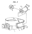
- Fig. 2 is a perspective view of the throttle device of Fig. 1, wherein a part (motor casing) 1b of the device 1b is shown with a section view, and the throttle actuator (motor) removed from the motor casing 1b is shown with a perspective view.
- Fig. 3 is an illustration of the steps in the process of inserting the motor into the throttle body and assembling them.
- the throttle body 1 shown in Figs. 1 to 3 is made by aluminum die-casting. Formed inside the throttle body 1 is a bore serving as an air-intake passage 1a. A throttle valve 2 is disposed in the air-intake passage 1a.
- the throttle valve 2 is fixed to a throttle shaft 3, which is supported through the throttle body 1, by set screws 4.
- the throttle shaft 3 is supported rotatably with bearings 5a and 5b.
- the bearing 5a is held by the throttle body 1 and a retainer plate 6a.
- the bearing 5b is held by the throttle body 1 and a retainer plug 6b and one end face is covered.
- a motor casing 1b is molded integrally together with the throttle body 1a.
- the yoke (motor body) 71 of the motor 7 for driving the throttle valve is inserted into the motor casing 1b.
- the motor 7 has an output shaft 70 in which one end (front side) protrude thorough the end bracket, and the output shaft 70a is provided with a pinion 8 for transmitting power from the motor 7 to the throttle shaft 3.
- An intermediate gear 9 for transmitting power from the motor is fitted on a shaft 11 being press-fitted into the throttle body 1.
- a throttle gear 10 is fixed on the front end of the throttle shaft 3 by a skirt nut 12.
- the gears 8, 9, and 10 constitute a reduction device for transmitting power from the motor 7 to the throttle shaft 3. They are covered in a sealed state with a packing 14 and a gear cover 13 attached to the throttle body 1.
- the gear cover 13 is made of synthetic resin.
- the gear cover 13 has a metal motor-driving terminal 13a and a throttle-sensor terminal 13b, the terminals 13a and 13b together provided into the cover 13 by insert molding. In this way, the gear cover is provided with a so-called directly mounting connector 13c and a throttle sensor.
- the throttle sensor has a rotor 20 and a resistor 19.
- the rotor 20 is fitted to one end side part of the throttle shaft 3.
- the rotor 20 has a brush 13b, which is in contact with the resistor 19 of the sensor.
- the throttle-sensor resistor 19 and the throttle-sensor terminal 18 are held by U-clip having spring elasticity. Thus, the resistor 19 and the throttle-sensor terminal 18 are electrically connected by mechanical contact.
- the art of driving and controlling a throttle valve with an electric motor is well known; therefore, the explanation of the art is omitted.
- a numeral 15 is a return spring
- a numeral 16 is a default lever
- a numeral 17 is a default spring
- a motor body 71 is inserted into the motor casing 1b through a motor-insertion opening 73.
- the one end portion 72 (flange 7b) on the output shaft side of the motor 7 is held and fixed in its radial direction in the vicinity of the motor-insertion opening 73 of the motor casing 1b.
- the other end portion 74 opposite to the output shaft side of the motor 7 is held in motor's radial direction by the inner surface of the motor casing 1b through the use of elastic pieces 7c (it may be so "flexible pieces"; refer to Figs 2 and 3).
- the motor body and the elastic pieces are formed in a single-piece design (or the elastic pieces are attached to the motor as shown in other embodiments to be described later).
- the elastic pieces are elastic-deformed inwardly in the radial direction of the motor by pressure from the inner surface of motor casing 1b.
- the elastic pieces (namely flexible pieces or springy pieces) 7c and a bearing bracket 7a opposite to an output-shaft side (rear end) of the motor are formed in a single-piece design.
- the elastic 7c are configured by bent-pieces which are formed on an outer edge of the bearing bracket 7a by sheet-metal working.
- the number and arrangement of spring pieces 7c are not limited to them.
- the bent pieces 7c extend radially from the outer edge of the bearing bracket in a state before bending working, and they are formed by being bent from the motor rear side toward the motor front side (output-shaft side of the motor). The bending direction of the bent pieces is opposite to the direction of inserting the motor.
- Each bent piece 7c has a curved surface (see Fig. 3).
- part of the curved outer surfaces of the bent pieces 7c come into contact with a tapered surface 1f inside the motor casing 1b and are pressed down inwardly in the radial direction of the motor.
- the motor casing 1b is configured by a cylindrical casing in which one end thereof is closed, and the other end thereof is provided with the motor-insertion opening 73.
- Inside of the motor casing 1b has a tapered surface (1e, 1f) tapering down from the motor 7-insertion opening side to toward the side opposite to the motor-insertion opening.
- the tapered surface is configured with a first tapered surface part 1e making up a sizable proportion thereof (it extends from the motor-insertion opening side toward the deep recess-portion of the motor casing) and a second tapered surface part 1f following the first tapered surface part 1e at the deep recess-portion.
- the slope of the second tapered surface 1f is larger than that of the first tapered surface 1e.
- the bent pieces 7c come into contact with the second tapered surface 1f immediately before the motor 7 is fully inserted into the motor casing 1b as shown in Fig. 3 (3). Then, as the motor 7 is fully inserted into the motor casing 1b, the bent pieces 7c are pressed down by the second tapered surface part 1f and are elastically deformed in the inner radial direction of the motor.
- bent pieces 7c have a curved outer surface, their curved outer surfaces comes into contact with the second tapered surface 1f of the motor casing 1b and, thus, the bent pieces 7c are pressed down.
- Parts 7b" (the parts made longer than the part 7b' in the radial direction) of the flange 7b are positioned between motor guide projections 1d.
- Each parts 7b" has a screw-through hole 80 (see Fig. 2), and the motor 7 is secured to the throttle 1 by screws using the screw-through holes 80.
- the parts 7b' (having smaller diameters than the parts 7b") of the flange 7b are clearance-fitted into the motor-guide (flange guide) 1d immediately before the motor 7 is fully inserted into the motor casing 1b.
- the end on the output-shaft side 72 of the motor 7 is fixed in its radial direction.
- the reference sign "L1" is a distance from a point p1 to the end of the motor guide projections (motor guide) 1d.
- the point P1 is a point where elastic pieces (bent pieces) 7c of the motor 7 first come into contact with the second tapered surface 1f during the motor insertion process.
- “L2,” is a distance from the point "P” to the flange 7b on the output-shaft side. L1 is equal to or larger than L2).
- Fig. 3 (1) shows the position before the bent pieces 7c reach the contact point "P" to the position shown in Fig. 3 (2).
- Fig. 3 (2) shows the position of the motor 7 immediately before it is fully inserted into the motor casing 1b, namely the position of the motor 7 where the bent pieces 7c reach the contact point "P" on the second tapered surface 1f.
- L1 is not shorter than L2
- the outer edge of the flange 7b (the end on the output side of the motor) is clearance-fitted into inner faces of the motor guide projections 1d.
- the motor flange 7b is supported by the motor guide projections 1d.
- the center of the end 74 opposite to the output-shaft side of the motor 7 is aligned with the center of the motor casing 1b by the bent pieces 7c coming into contact with the second tapered surface 1f.
- the bent pieces 7c are pressed down by the second tapered surface 1f and, then, by the non-tapered inner surface 1c as shown in Fig. 3 (3) and are elastically deformed (flexibly deformed) inwardly of the radial direction of the motor.
- the bent pieces 7c partially enter the notches 75 and the rear end 74 of the motor body 71 is firmly held in the inner surface 1c of the motor casing by the elasticity (springy force) of the pressed-down bent pieces 7c.
- the precision in assembling the motor 7 and vibration resistance of the motor 7 are improved.
- the number of parts is relatively small and the assembling process of the motor 7 is relatively simple.
- the elastic pieces 7c have a curved outer surface and the halfway parts of curved outer surfaces are pressed down by the second tapered surface 1f (inside of the casing), the elastic pieces 7c do not scrape the inside of the motor casing 1b, producing no metal scraps.
- Figs. 4 to 8 are partially sectional views of other embodiments of the present invention.
- the same reference numerals and signs commonly used between Figs. 1 to 3 stand for the same components and elements. The differences from the first embodiment will be described below.
- the motor body 71 as a yoke is provided with elastic pieces 7e.
- the elastic pieces 7e such as lugs are formed by cutting and raising parts of the yoke 71 of the motor 7.
- the elastic pieces 7e are arranged in a circumferential direction of the yoke 71.
- the yoke 7 is fitted with a ring (a part different from the yoke) 7f' with elastic pieces (flexible pieces like plate springs) 7f.
- the elastic projections (lugs) 7f are formed and arranged in a circumferential direction of the ring 7f' by cutting parts of the ring 7f' in the shape of a lug and raising them.
- the bearing boss 77 at the rear end of the motor 7 is fitted with a ring 7g' with elastic pieces 7g (or elastic projections).
- This ring 7g' has the same workings and effect as the rings of the other embodiments.
- the contact point "P" of the elastic pieces 7g is somewhere on the inner surface of the boss 77.
- the previously described relation between "L1" and “L2" that "L1" is not shorter than “L2” holds true in this embodiment.
- the present embodiment has the same workings and effect as those of the previously described embodiments.
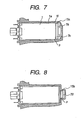
- Figs. 7 and 8 show other embodiments.
- one end of the yoke 7 is provided with a circumferential groove 79, and an O-ring (elastic member) 15a is fitted therein.
- the O-ring has the same effect as that of the previously described elastic pieces.
- the previously described relation between "L1" and “L2" that "L1" is not shorter than “L2” also holds true in this embodiment.
- the bearing boss 78 at the rear end of the yoke 7 is provided with a circumferential groove 79', and an O-ring 15b is fitted therein.
- the contact point "P" of the O-ring 15b is somewhere on the inner surface of the boss 78.
- the previously described relation between "L1" and “L2" that the L1 is not shorter than “L2” also holds true in this embodiment.
- the present embodiment has the same workings and effect as those of the previously described embodiments.
- the elastic pieces, rings, etc. may be made of synthetic resin. The present invention is not limited to the above embodiments, and various types of elastic pieces, elastic projections, etc. are applicable.
- a throttle device and a motor therefor in which vibration resistance of the motor and the precision in assembling the motor (precision of alignment of the motor) are improved with simple configuration can be provided.
Landscapes
- Engineering & Computer Science (AREA)
- Chemical & Material Sciences (AREA)
- Combustion & Propulsion (AREA)
- Mechanical Engineering (AREA)
- General Engineering & Computer Science (AREA)
- Manufacturing & Machinery (AREA)
- Motor Or Generator Frames (AREA)
- Control Of Throttle Valves Provided In The Intake System Or In The Exhaust System (AREA)
- Electrically Driven Valve-Operating Means (AREA)
Abstract
Description
- This invention relates to a throttle device and a motor therefor used to control the flow rate of air flowing into a cylinder of an internal-combustion engine.
- A throttle device wherein throttle valves disposed in an air-intake passage of a throttle body are electrically driven by a motor is already known. A body of the motor is housed in a motor casing, and the throttle body and the motor casing are formed as a single piece.
- Proposed is the art of improving vibration resistance of such a body of the motor by fixing its front and rear ends in its radial direction (Both-end supporting structure). The following mechanisms for holding the output shaft and the rear end (an end opposite to the output-shaft side) of such a motor are disclosed.
- According to
Japanese Patent Laid-Open Nos. 2002-339766 H10-252510 - To put it more concretely, according to
Japanese Patent Laid-Open No. 2002-339766 - On the other hand, according to
Japanese Patent Laid-Open No. H10-252510 - In the case of the former prior art, when the motor is inserted into the motor, casing to bend the inner cut zone of the washer backward. During such motor insertion process, the outside of the motor body (yoke) may be scraped by the inner edge of the washer, and metal scraps may be produced. In addition, when inserting the motor into the motor casing, the motor may be inserted having dislingnment and held in such a state because there is no means of aligning the center of the rear end of the motor. The disalignment of the center line of the motor with the center line of the motor casing means the disalignment of the motor's driving gears with a pinion gear and an intermediate gear and causes an error in mounting the motor.
- In the case of the latter prior art, when the motor with the elastic O-ring is inserted into the motor casing, the elastic O-ring may be distorted or damaged.
- The object of the present invention is to provide a throttle device with a motor, which is free from the above problems and of relatively simple construction.
- According to the present invention, in a throttle device with a motor for driving a throttle valve, the motor is housed in a motor casing provided in a throttle body. Additionally, an output-shaft side of the motor (here, it's also called as "front side or front end") is held in its radial directions in the vicinity of the motor casing's opening for inserting the motor into the motor casing. Another side (it's also called "rear side" or "rear end") opposite to the output shaft is provided with projections (elastic projections, for example), which are deformed inwardly in a radial directions. The motor and the elastic projections are formed in a single piece, or the elastic projections are attached to the motor body. According to the deformation of the projection, the projections contact to the inside surface of the motor casing adding pressure, the rear end of the motor is held and fixed in its radial direction in the motor casing.
- The elastic projections may be bent projections or lugs arranged circumferentially of the rear end of the motor.
- With the above configuration, the motor is aligned with the motor casing immediately before the motor body is fully inserted into the motor casing; therefore, the motor can be properly aligned (alignment in its radial direction) with the throttle body.
- When the motor is further inserted (fully inserted) into the motor casing, the elastic projections of the end opposite to the output-shaft side (rear end) of the motor are pressed down in the radial direction of the motor by the inside surface of the motor casing; thus, the rear end of the motor is held and fixed in its radial directions in the motor casing, the motor output shaft is kept precisely in parallel with an intermediate gear shaft and a throttle valve shaft. Therefore, the motor gear engages with the intermediate gear in good condition. That is, this arrangement is prevent from disalignment of the motor and no good mesh of gears with no good gear pitch due to such disalignment. As described above, the portion on the output-shaft side in the motor body is fixed to the throttle body, and the rear side of the motor body is held and fixed in its radial directions by the pressed-down (preferably elastic) projections in the motor casing; therefore, the motor's vibration in its radial directions is held down. Thus, the vibration resistance of the motor is improved. As described above, the rear side portion of the motor is held and fixed inside the casing by the elasticity of the pressed-down elastic projections. Alternatively, the rear side portion of the motor may be held and fixed by similar projections, for example, which are press-fitted into the motor casing to be physically deformation.
-
- Fig. 1 is a sectional view of a typical motor-driven throttle device (a device for controlling air intake for internal-combustion engines) of the present invention;
- Fig. 2 is a perspective view of the throttle device of Fig. 1; wherein a section of part of the unit (motor casing) 1b is shown, and a perspective view of the throttle actuator (motor) removed from the motor casing is presented;
- Fig. 3 is an illustration of the steps in the process of inserting the motor into the throttle body and assembling them; and
- Figs. 4 to 8 are partially sectional views of other embodiments of the present invention.
- By referring to the drawings, a preferred embodiment of the present invention will be described below.
- Fig. 1 is a sectional view of a typical motor-driven throttle devise (a device for controlling air intake flow rate for internal-combustion engines) of the present invention. Fig. 2 is a perspective view of the throttle device of Fig. 1, wherein a part (motor casing) 1b of the
device 1b is shown with a section view, and the throttle actuator (motor) removed from themotor casing 1b is shown with a perspective view. Fig. 3 is an illustration of the steps in the process of inserting the motor into the throttle body and assembling them. - The throttle body (also referred to as "main body" or "bore body") 1 shown in Figs. 1 to 3 is made by aluminum die-casting. Formed inside the
throttle body 1 is a bore serving as an air-intake passage 1a. Athrottle valve 2 is disposed in the air-intake passage 1a. - The
throttle valve 2 is fixed to athrottle shaft 3, which is supported through thethrottle body 1, by setscrews 4. Thethrottle shaft 3 is supported rotatably withbearings throttle body 1 and aretainer plate 6a. The bearing 5b is held by thethrottle body 1 and aretainer plug 6b and one end face is covered. - A
motor casing 1b is molded integrally together with thethrottle body 1a. The yoke (motor body) 71 of themotor 7 for driving the throttle valve is inserted into themotor casing 1b. - The
motor 7 has anoutput shaft 70 in which one end (front side) protrude thorough the end bracket, and the output shaft 70a is provided with apinion 8 for transmitting power from themotor 7 to thethrottle shaft 3. - An
intermediate gear 9 for transmitting power from the motor is fitted on ashaft 11 being press-fitted into thethrottle body 1. Athrottle gear 10 is fixed on the front end of thethrottle shaft 3 by askirt nut 12. Thegears motor 7 to thethrottle shaft 3. They are covered in a sealed state with apacking 14 and agear cover 13 attached to thethrottle body 1. - The
gear cover 13 is made of synthetic resin. Thegear cover 13 has a metal motor-driving terminal 13a and a throttle-sensor terminal 13b, theterminals cover 13 by insert molding. In this way, the gear cover is provided with a so-called directly mountingconnector 13c and a throttle sensor. The throttle sensor has arotor 20 and aresistor 19. Therotor 20 is fitted to one end side part of thethrottle shaft 3. Therotor 20 has abrush 13b, which is in contact with theresistor 19 of the sensor. The throttle-sensor resistor 19 and the throttle-sensor terminal 18 are held by U-clip having spring elasticity. Thus, theresistor 19 and the throttle-sensor terminal 18 are electrically connected by mechanical contact. The art of driving and controlling a throttle valve with an electric motor is well known; therefore, the explanation of the art is omitted. - As shown in Fig. 1, a numeral 15 is a return spring, a numeral 16 is a default lever, and a numeral 17 is a default spring.
- The arrangement for holding the
motor 7 for the throttle device will be detailed below. - In the
motor 7 of the present embodiment, amotor body 71 is inserted into themotor casing 1b through a motor-insertion opening 73. The one end portion 72 (flange 7b) on the output shaft side of themotor 7 is held and fixed in its radial direction in the vicinity of the motor-insertion opening 73 of themotor casing 1b. Theother end portion 74 opposite to the output shaft side of themotor 7 is held in motor's radial direction by the inner surface of themotor casing 1b through the use ofelastic pieces 7c (it may be so "flexible pieces"; refer to Figs 2 and 3). The motor body and the elastic pieces are formed in a single-piece design (or the elastic pieces are attached to the motor as shown in other embodiments to be described later). The elastic pieces are elastic-deformed inwardly in the radial direction of the motor by pressure from the inner surface ofmotor casing 1b. - As shown in Fig. 2, the elastic pieces (namely flexible pieces or springy pieces) 7c and a
bearing bracket 7a opposite to an output-shaft side (rear end) of the motor are formed in a single-piece design. The elastic 7c are configured by bent-pieces which are formed on an outer edge of thebearing bracket 7a by sheet-metal working. Although there are four elastic pieces (bent pieces like metal plate springs) 7c at evenly spaced intervals in Fig. 2, the number and arrangement ofspring pieces 7c are not limited to them. - The
bent pieces 7c extend radially from the outer edge of the bearing bracket in a state before bending working, and they are formed by being bent from the motor rear side toward the motor front side (output-shaft side of the motor). The bending direction of the bent pieces is opposite to the direction of inserting the motor. Eachbent piece 7c has a curved surface (see Fig. 3). - Immediately before the
motor 7 is fully inserted into themotor casing 1b, part of the curved outer surfaces of thebent pieces 7c come into contact with atapered surface 1f inside themotor casing 1b and are pressed down inwardly in the radial direction of the motor. - The above pressing will be detailed later when the process of installing the motor body into the motor casing is described by referring to Fig. 3. When pressed down, the
bent pieces 7c are elastically deformed (flexibly deformed) inwardly in the directions of the motor. Due to such elastic deformation, thebent pieces 7c come intonotches 75 which are made in theyoke 71 of themotor 7. - The
motor casing 1b is configured by a cylindrical casing in which one end thereof is closed, and the other end thereof is provided with the motor-insertion opening 73. Inside of themotor casing 1b has a tapered surface (1e, 1f) tapering down from the motor 7-insertion opening side to toward the side opposite to the motor-insertion opening. In this embodiment, the tapered surface is configured with a first taperedsurface part 1e making up a sizable proportion thereof (it extends from the motor-insertion opening side toward the deep recess-portion of the motor casing) and a secondtapered surface part 1f following the first taperedsurface part 1e at the deep recess-portion. - The slope of the second tapered
surface 1f is larger than that of the first taperedsurface 1e. When themotor 7 is fully inserted into themotor casing 1b, the rear end of themotor 7 is positioned at the non-taperedinner surface part 1c between the second taperedsurface part 1f and the rear end (inner bottom) 1h of themotor casing 1b as shown in Figs. 1 and 3. The non-taperedinner surface part 1c is formed in a straight cylindrical-inner surface shape. - As shown in Fig. 3, there is a gap between the outer surface of the
motor 7 and the motor casing-inner surface comprising the first taperedsurface part 1e, the second taperedsurface part 1f and the non-taperedinner surface part 1c. The sum R1 of outer diameter of the motor-body 7 and the height at the highest points of the curved outer surfaces of thebent pieces 7c before the bent pieces (elastic pieces) are elastically deformed is larger than the inner diameter R2 at a halfway point "P" on the second taperedsurface part 1f. But the sum diameter R1 is smaller than the inner diameter R3 at any point of the range from the first taperedsurface part 1e up to a position immediately before the halfway point "P" of the second taperedsurface part 1f. Accordingly, thebent pieces 7c come into contact with the second taperedsurface 1f immediately before themotor 7 is fully inserted into themotor casing 1b as shown in Fig. 3 (3). Then, as themotor 7 is fully inserted into themotor casing 1b, thebent pieces 7c are pressed down by the second taperedsurface part 1f and are elastically deformed in the inner radial direction of the motor. - Because the
bent pieces 7c have a curved outer surface, their curved outer surfaces comes into contact with the second taperedsurface 1f of themotor casing 1b and, thus, thebent pieces 7c are pressed down. - A
motor guide 1d for guiding motor inserting are formed in the vicinity of the motor-insertion opening 73 of themotor casing 1b. As shown in Fig. 2, themotor guide 1d is configured by plural guide projections formed in the vicinity of the motor-insertion opening 73, and have arc-shaped inner faces respectively. The end on the output-shaft side of themotor 7 is restrained in the radial direction by the ark-shaped inner face of themotor guide 1d (for example, apart 7b' (see Fig. 2) of a motor-mountingflange 7b of themotor body 71 are put into contact with the arc-shaped inner faces of themotor guide 1d).Parts 7b" (the parts made longer than thepart 7b' in the radial direction) of theflange 7b are positioned betweenmotor guide projections 1d. Eachparts 7b" has a screw-through hole 80 (see Fig. 2), and themotor 7 is secured to thethrottle 1 by screws using the screw-through holes 80. - The
parts 7b' (having smaller diameters than theparts 7b") of theflange 7b are clearance-fitted into the motor-guide (flange guide) 1d immediately before themotor 7 is fully inserted into themotor casing 1b. Thus, the end on the output-shaft side 72 of themotor 7 is fixed in its radial direction. - By referring to Fig. 3, the process of mounting the
motor 7 into themotor casing 1b will be described below. - In Fig. 3, the reference sign "L1" is a distance from a point p1 to the end of the motor guide projections (motor guide) 1d. The point P1 is a point where elastic pieces (bent pieces) 7c of the
motor 7 first come into contact with the second taperedsurface 1f during the motor insertion process. "L2," is a distance from the point "P" to theflange 7b on the output-shaft side. L1 is equal to or larger than L2). - As the
motor 7 is inserted into themotor casing 1b, themotor 7 moves from the position shown in Fig. 3 (1) (the position before thebent pieces 7c reach the contact point "P") to the position shown in Fig. 3 (2). Fig. 3 (2) shows the position of themotor 7 immediately before it is fully inserted into themotor casing 1b, namely the position of themotor 7 where thebent pieces 7c reach the contact point "P" on the second taperedsurface 1f. At the time, because L1 is not shorter than L2, the outer edge of theflange 7b (the end on the output side of the motor) is clearance-fitted into inner faces of themotor guide projections 1d. - Thus, in the step of inserting the
motor 7 into themotor casing 1b shown in Fig. 3 (2), themotor flange 7b is supported by themotor guide projections 1d. On the other hand, the center of theend 74 opposite to the output-shaft side of themotor 7 is aligned with the center of themotor casing 1b by thebent pieces 7c coming into contact with the second taperedsurface 1f. - Then, when the
motor 7 is fully inserted into themotor casing 1b, thebent pieces 7c are pressed down by the second taperedsurface 1f and, then, by the non-taperedinner surface 1c as shown in Fig. 3 (3) and are elastically deformed (flexibly deformed) inwardly of the radial direction of the motor. Thus, thebent pieces 7c partially enter thenotches 75 and therear end 74 of themotor body 71 is firmly held in theinner surface 1c of the motor casing by the elasticity (springy force) of the pressed-downbent pieces 7c. - In the above step of full insertion, the
motor flange 7b is guided by themotor guide projections 1d; therefore, themotor 7 is fully inserted into themotor casing 1b correctly. - Thus, the precision in assembling the
motor 7 and vibration resistance of themotor 7 are improved. Besides, as thebent pieces 7c and themotor 7 are formed as a single piece, the number of parts is relatively small and the assembling process of themotor 7 is relatively simple. Moreover, because theelastic pieces 7c have a curved outer surface and the halfway parts of curved outer surfaces are pressed down by the second taperedsurface 1f (inside of the casing), theelastic pieces 7c do not scrape the inside of themotor casing 1b, producing no metal scraps. - Figs. 4 to 8 are partially sectional views of other embodiments of the present invention. The same reference numerals and signs commonly used between Figs. 1 to 3 stand for the same components and elements. The differences from the first embodiment will be described below.
- In Fig. 4, the
motor body 71 as a yoke is provided withelastic pieces 7e. Theelastic pieces 7e such as lugs are formed by cutting and raising parts of theyoke 71 of themotor 7. As in the case of the first embodiment, theelastic pieces 7e are arranged in a circumferential direction of theyoke 71. The relation between "L1" and "L2" of the first embodiment that "L1" is not shorter than "L2" holds true in this embodiment. - In Fig. 5, the
yoke 7 is fitted with a ring (a part different from the yoke) 7f' with elastic pieces (flexible pieces like plate springs) 7f. The elastic projections (lugs) 7f are formed and arranged in a circumferential direction of thering 7f' by cutting parts of thering 7f' in the shape of a lug and raising them. - In Fig. 6, the bearing
boss 77 at the rear end of themotor 7 is fitted with aring 7g' withelastic pieces 7g (or elastic projections). Thisring 7g' has the same workings and effect as the rings of the other embodiments. In this embodiment, the contact point "P" of theelastic pieces 7g is somewhere on the inner surface of theboss 77. Also, the previously described relation between "L1" and "L2" that "L1" is not shorter than "L2" holds true in this embodiment. Thus, the present embodiment has the same workings and effect as those of the previously described embodiments. - Figs. 7 and 8 show other embodiments. In Fig. 7, one end of the
yoke 7 is provided with acircumferential groove 79, and an O-ring (elastic member) 15a is fitted therein. The O-ring has the same effect as that of the previously described elastic pieces. The previously described relation between "L1" and "L2" that "L1" is not shorter than "L2" also holds true in this embodiment. - In Fig. 8, the bearing boss 78 at the rear end of the
yoke 7 is provided with a circumferential groove 79', and an O-ring 15b is fitted therein. In this embodiment, the contact point "P" of the O-ring 15b is somewhere on the inner surface of the boss 78. The previously described relation between "L1" and "L2" that the L1 is not shorter than "L2" also holds true in this embodiment. Further, the present embodiment has the same workings and effect as those of the previously described embodiments. In addition to metal materials, the elastic pieces, rings, etc. may be made of synthetic resin. The present invention is not limited to the above embodiments, and various types of elastic pieces, elastic projections, etc. are applicable. - According to the present invention, a throttle device and a motor therefor in which vibration resistance of the motor and the precision in assembling the motor (precision of alignment of the motor) are improved with simple configuration can be provided.
Claims (14)
- A throttle device comprising a throttle body with an air-intake passage, a throttle valve for controlling the opening of said air-intake passage, and a motor for driving said throttle valve;
said throttle device further comprising:a motor casing which is molded integrally together with said throttle body and houses a motor body of said motor;a portion which is on an output-shaft side of said motor body and restrained in its radial direction in the vicinity of a motor-insertion opening of said motor casing;a portion which is on opposite side to the output-shaft side of said motor body and provided with projections; andsaid projections formed in a single piece together with said motor body or attached to said motor body;wherein said projections are deformed inwardly in a radial direction of said motor body by being pressed down by an inner surface of said motor casing so that said portion opposite to the output-shaft side in said motor body is held in its radial direction in said motor casing. - A throttle device comprising a throttle body with an air-intake passage, a throttle valve for controlling the opening of said air-intake passage, and a motor for driving said throttle valve;
said throttle device further comprising:a motor casing which is molded integrally together with said throttle body and houses a motor body of said motor;a portion which is on an output-shaft side in said motor body and restrained in its radial direction in the vicinity of a motor-insertion opening of said motor casing; anda portion which is on opposite side to the output-shaft side in said motor body and provided with plural bent pieces or lugs arranged in a circumferential direction of said motor body;wherein said bent pieces or lugs are deformed inwardly in a radial direction of said motor body by being pressed down at a deep recess-portion of said motor casing by an inner surface of said motor casing so that said portion opposite to the output-shaft side in said motor body is held in its radial direction in said motor casing. - The throttle device according to claim 1,
wherein said projections are elastic projections. - The throttle device according to claim 1,
wherein two or more said projections are arranged in a circumferential direction of said motor body. - The throttle device according to claim 2,
wherein two or more said bent pieces or lugs are formed in a single piece together with a component of said motor or formed so as to be attachable to said motor body, and they are arranged in a circumferential direction of said motor body. - The throttle device according to claim 1 or 2 further comprising a motor guide formed in the vicinity of the motor-insertion opening of said motor casing;
wherein the portion on the output-shaft side in said motor body is designed so as to be clearance-fitted into an inner surface of said motor guide before said motor is fully inserted into said motor casing, and the portion on the output-shaft side in said motor body is restrained in its radial direction by said motor guide. - The throttle device according to claim 1 or 2 further comprising a motor guide formed in the vicinity of the motor-insertion opening of said motor casing;
wherein a motor-mounting flange on the output-shaft side of said motor body is designed so as to be clearance-fitted into an inner face of said motor guide, and the portion on the output-shaft side of said motor body is restrained in its radial direction by said motor guide. - The throttle device according to claim 2 further comprising a taper which is formed on at least a part of the inside surface of said motor casing so as to taper down from a motor insertion side toward a side opposite to said motor insertion side;
wherein said bent pieces or lugs have respectively curved outer surfaces, and said curved outer surfaces come into contact with said taper of said motor casing so that said bent pieces or lugs are pressed down. - A throttle valve driving motor comprising projections formed in one-single piece together with a component of a motor body or attached to said motor body,
wherein said projections is arranged on a portion opposite to an output-shaft side in said motor body and capable of contacting with pressure and its deformation to an inside surface of a motor casing for hosing a motor body of said motor. - The throttle valve driving motor according to claim 9,
wherein said projections are flexibly deformable projections and formed in one-single piece together with a bearing bracket or a yoke on the side opposite to the output-shaft side of said motor. - The throttle valve driving motor according to claim 9,
wherein said projections comprise plural bent pieces which are arranged on outer circumference of a bearing bracket at a portion opposite to the output-shaft side of said motor body by sheet-metal working; and
wherein a yoke of said motor is provided with notches for receiving said bent pieces when they are elastically deformed. - The throttle valve driving motor according to claim 9,
wherein said projections are plural rugs by cutting and raising locally a yoke of said motor and arranged in a circumferential direction of said motor body. - The throttle valve driving motor according to claim 9, wherein said projections are formed on a ring attached to an outer circumference of a yoke of said motor body.
- The throttle valve driving motor according to claim 9, wherein said projections are formed on a ring attached to an outer circumference of a bearing boss of said motor body.
Applications Claiming Priority (1)
| Application Number | Priority Date | Filing Date | Title |
|---|---|---|---|
| PCT/JP2003/014921 WO2005049991A1 (en) | 2003-11-21 | 2003-11-21 | Throttle device and motor used for the throttle device |
Publications (3)
| Publication Number | Publication Date |
|---|---|
| EP1701020A1 true EP1701020A1 (en) | 2006-09-13 |
| EP1701020A4 EP1701020A4 (en) | 2010-07-07 |
| EP1701020B1 EP1701020B1 (en) | 2012-03-21 |
Family
ID=34611324
Family Applications (1)
| Application Number | Title | Priority Date | Filing Date |
|---|---|---|---|
| EP03819031A Expired - Lifetime EP1701020B1 (en) | 2003-11-21 | 2003-11-21 | Throttle device and motor used for the throttle device |
Country Status (5)
| Country | Link |
|---|---|
| US (1) | US7469879B2 (en) |
| EP (1) | EP1701020B1 (en) |
| JP (1) | JP4231050B2 (en) |
| CN (1) | CN1878937B (en) |
| WO (1) | WO2005049991A1 (en) |
Cited By (2)
| Publication number | Priority date | Publication date | Assignee | Title |
|---|---|---|---|---|
| EP1544438A3 (en) * | 2003-12-19 | 2011-07-06 | Denso Corporation | Supporting device for actuator received in housing |
| US11047349B2 (en) | 2017-08-09 | 2021-06-29 | Honda Motor Co., Ltd. | Intake structure of engine |
Families Citing this family (12)
| Publication number | Priority date | Publication date | Assignee | Title |
|---|---|---|---|---|
| DE102004011753B3 (en) | 2004-03-09 | 2005-09-29 | Tesma Europa Gmbh | filler cap |
| JP2006097500A (en) * | 2004-09-28 | 2006-04-13 | Honda Motor Co Ltd | General-purpose engine throttle device |
| JP4490897B2 (en) * | 2005-10-14 | 2010-06-30 | 愛三工業株式会社 | Electronically controlled throttle valve device |
| TWI484095B (en) * | 2011-11-23 | 2015-05-11 | Kwang Yang Motor Co | Engine throttle control structure |
| FR3014525B1 (en) * | 2013-12-11 | 2016-04-29 | Valeo Systemes De Controle Moteur | VALVE BODY WITH OPTIMIZED HOUSING FOR RECEIVING AN ENGINE |
| FR3014526B1 (en) * | 2013-12-11 | 2016-04-29 | Valeo Systemes De Controle Moteur | VALVE BODY WITH OPTIMIZED HOUSING FOR RECEIVING AN ENGINE |
| FR3058200A1 (en) * | 2016-11-03 | 2018-05-04 | Valeo Systemes De Controle Moteur | MOTOR CONTROL ACTUATOR AND FLUID CIRCULATION VALVE COMPRISING SAME |
| FR3059060B1 (en) * | 2016-11-22 | 2019-07-19 | Valeo Systemes De Controle Moteur | DEVICE FOR MAINTAINING AN ELECTRIC MOTOR IN AN ACTUATOR BODY |
| FR3074621A1 (en) * | 2017-12-01 | 2019-06-07 | Valeo Systemes De Controle Moteur | ELECTRIC MOTOR FOR MOTOR CONTROL ACTUATOR AND ACTUATOR COMPRISING SAME |
| KR102146657B1 (en) * | 2017-12-27 | 2020-08-21 | 주식회사 현대케피코 | Throttle valve assembly |
| JP7124792B2 (en) * | 2019-06-07 | 2022-08-24 | 株式会社デンソー | Cover device for motor terminals |
| US12546409B2 (en) * | 2024-05-17 | 2026-02-10 | Buerkert Werke Gmbh & Co. Kg | Valve unit and method for producing the valve unit |
Family Cites Families (11)
| Publication number | Priority date | Publication date | Assignee | Title |
|---|---|---|---|---|
| JPS47607U (en) | 1971-01-19 | 1972-08-04 | ||
| JPS5251976A (en) | 1975-10-24 | 1977-04-26 | Hitachi Ltd | Chatter time measuring system |
| JPS52127616A (en) | 1976-04-19 | 1977-10-26 | Nippon Kokan Kk <Nkk> | Connecting method for socket and spigot joint with rubber ring |
| DE4342949A1 (en) * | 1993-12-16 | 1995-06-22 | Bosch Gmbh Robert | Arrangement for clearance-free fixing of electric machine into casing |
| DE69627401T3 (en) * | 1995-01-17 | 2014-01-30 | Hitachi, Ltd. | Airflow control device |
| JP3364873B2 (en) | 1997-03-13 | 2003-01-08 | 株式会社日立ユニシアオートモティブ | Electronically controlled throttle valve device for internal combustion engine |
| JP3404254B2 (en) * | 1997-05-07 | 2003-05-06 | 株式会社日立製作所 | Engine throttle device |
| JP2001346351A (en) * | 2000-05-31 | 2001-12-14 | Asmo Co Ltd | Motor and throttle actuator |
| JP2002339766A (en) * | 2001-05-15 | 2002-11-27 | Aisan Ind Co Ltd | Throttle valve control device |
| DE10138060A1 (en) * | 2001-08-03 | 2003-02-20 | Bosch Gmbh Robert | Throttle device with drive holder and drive contact |
| JP4056724B2 (en) | 2001-10-01 | 2008-03-05 | 株式会社日立製作所 | Engine throttle device |
-
2003
- 2003-11-21 US US10/580,113 patent/US7469879B2/en not_active Expired - Lifetime
- 2003-11-21 JP JP2005510764A patent/JP4231050B2/en not_active Expired - Fee Related
- 2003-11-21 WO PCT/JP2003/014921 patent/WO2005049991A1/en not_active Ceased
- 2003-11-21 CN CN2003801107260A patent/CN1878937B/en not_active Expired - Fee Related
- 2003-11-21 EP EP03819031A patent/EP1701020B1/en not_active Expired - Lifetime
Cited By (2)
| Publication number | Priority date | Publication date | Assignee | Title |
|---|---|---|---|---|
| EP1544438A3 (en) * | 2003-12-19 | 2011-07-06 | Denso Corporation | Supporting device for actuator received in housing |
| US11047349B2 (en) | 2017-08-09 | 2021-06-29 | Honda Motor Co., Ltd. | Intake structure of engine |
Also Published As
| Publication number | Publication date |
|---|---|
| WO2005049991A1 (en) | 2005-06-02 |
| CN1878937A (en) | 2006-12-13 |
| JP4231050B2 (en) | 2009-02-25 |
| US20070069170A1 (en) | 2007-03-29 |
| US7469879B2 (en) | 2008-12-30 |
| EP1701020A4 (en) | 2010-07-07 |
| EP1701020B1 (en) | 2012-03-21 |
| JPWO2005049991A1 (en) | 2007-06-14 |
| CN1878937B (en) | 2010-09-29 |
Similar Documents
| Publication | Publication Date | Title |
|---|---|---|
| US7469879B2 (en) | Throttle device and motor therefor | |
| KR100361410B1 (en) | Dc motor | |
| CN101213726A (en) | Motors and transmission drive units for servo drives in automobiles | |
| CN101273511B (en) | Motor and its manufacturing process | |
| KR100790670B1 (en) | Supporting device for actuator received in housing | |
| CN101443986A (en) | Motor with speed reducer and method for manufacturing the same | |
| EP1091469A2 (en) | Cap for thrust bearing | |
| JP4093173B2 (en) | Throttle control device for internal combustion engine | |
| KR100948106B1 (en) | motor | |
| JP2004187378A (en) | Electric motor with reduction gear | |
| CN215058125U (en) | Electric pump | |
| JP4119294B2 (en) | Step motor and flow control valve equipped with the step motor | |
| KR100483234B1 (en) | Fuel pump | |
| US20070187193A1 (en) | Blocking device, gear-drive unit containing such a blocking device, and method for producing such a gear-drive unit | |
| CN102472327B (en) | Support device | |
| CN101421906B (en) | Motor assembly | |
| EP1400701B1 (en) | Water pump | |
| KR101067740B1 (en) | Step motor actuator | |
| JP4464697B2 (en) | Electric motor | |
| CN112771734A (en) | Windshield wiper motor and method of assembling a windshield wiper motor | |
| CN120720375A (en) | Drive device | |
| JP7463811B2 (en) | Electric pump | |
| JP3690385B2 (en) | DC motor | |
| KR100525715B1 (en) | Starter motor | |
| JP2005312226A (en) | Electric motor |
Legal Events
| Date | Code | Title | Description |
|---|---|---|---|
| PUAI | Public reference made under article 153(3) epc to a published international application that has entered the european phase |
Free format text: ORIGINAL CODE: 0009012 |
|
| 17P | Request for examination filed |
Effective date: 20060621 |
|
| AK | Designated contracting states |
Kind code of ref document: A1 Designated state(s): DE |
|
| DAX | Request for extension of the european patent (deleted) | ||
| RBV | Designated contracting states (corrected) |
Designated state(s): DE |
|
| A4 | Supplementary search report drawn up and despatched |
Effective date: 20100608 |
|
| 17Q | First examination report despatched |
Effective date: 20100908 |
|
| GRAC | Information related to communication of intention to grant a patent modified |
Free format text: ORIGINAL CODE: EPIDOSCIGR1 |
|
| GRAJ | Information related to disapproval of communication of intention to grant by the applicant or resumption of examination proceedings by the epo deleted |
Free format text: ORIGINAL CODE: EPIDOSDIGR1 |
|
| GRAP | Despatch of communication of intention to grant a patent |
Free format text: ORIGINAL CODE: EPIDOSNIGR1 |
|
| GRAS | Grant fee paid |
Free format text: ORIGINAL CODE: EPIDOSNIGR3 |
|
| GRAA | (expected) grant |
Free format text: ORIGINAL CODE: 0009210 |
|
| AK | Designated contracting states |
Kind code of ref document: B1 Designated state(s): DE |
|
| REG | Reference to a national code |
Ref country code: DE Ref legal event code: R096 Ref document number: 60340384 Country of ref document: DE Effective date: 20120510 |
|
| PLBE | No opposition filed within time limit |
Free format text: ORIGINAL CODE: 0009261 |
|
| STAA | Information on the status of an ep patent application or granted ep patent |
Free format text: STATUS: NO OPPOSITION FILED WITHIN TIME LIMIT |
|
| 26N | No opposition filed |
Effective date: 20130102 |
|
| REG | Reference to a national code |
Ref country code: DE Ref legal event code: R097 Ref document number: 60340384 Country of ref document: DE Effective date: 20130102 |
|
| PGFP | Annual fee paid to national office [announced via postgrant information from national office to epo] |
Ref country code: DE Payment date: 20191105 Year of fee payment: 17 |
|
| REG | Reference to a national code |
Ref country code: DE Ref legal event code: R119 Ref document number: 60340384 Country of ref document: DE |
|
| PG25 | Lapsed in a contracting state [announced via postgrant information from national office to epo] |
Ref country code: DE Free format text: LAPSE BECAUSE OF NON-PAYMENT OF DUE FEES Effective date: 20210601 |