EP1700901A1 - Vorrichtung zur Vergasung von Kohlenfeststoffen - Google Patents
Vorrichtung zur Vergasung von Kohlenfeststoffen Download PDFInfo
- Publication number
- EP1700901A1 EP1700901A1 EP06004671A EP06004671A EP1700901A1 EP 1700901 A1 EP1700901 A1 EP 1700901A1 EP 06004671 A EP06004671 A EP 06004671A EP 06004671 A EP06004671 A EP 06004671A EP 1700901 A1 EP1700901 A1 EP 1700901A1
- Authority
- EP
- European Patent Office
- Prior art keywords
- radiation
- reactor
- inlet
- source
- cavity
- Prior art date
- Legal status (The legal status is an assumption and is not a legal conclusion. Google has not performed a legal analysis and makes no representation as to the accuracy of the status listed.)
- Withdrawn
Links
Images



Classifications
-
- C—CHEMISTRY; METALLURGY
- C10—PETROLEUM, GAS OR COKE INDUSTRIES; TECHNICAL GASES CONTAINING CARBON MONOXIDE; FUELS; LUBRICANTS; PEAT
- C10J—PRODUCTION OF PRODUCER GAS, WATER-GAS, SYNTHESIS GAS FROM SOLID CARBONACEOUS MATERIAL, OR MIXTURES CONTAINING THESE GASES; CARBURETTING AIR OR OTHER GASES
- C10J3/00—Production of combustible gases containing carbon monoxide from solid carbonaceous fuels
- C10J3/72—Other features
- C10J3/723—Controlling or regulating the gasification process
-
- C—CHEMISTRY; METALLURGY
- C10—PETROLEUM, GAS OR COKE INDUSTRIES; TECHNICAL GASES CONTAINING CARBON MONOXIDE; FUELS; LUBRICANTS; PEAT
- C10G—CRACKING HYDROCARBON OILS; PRODUCTION OF LIQUID HYDROCARBON MIXTURES, e.g. BY DESTRUCTIVE HYDROGENATION, OLIGOMERISATION, POLYMERISATION; RECOVERY OF HYDROCARBON OILS FROM OIL-SHALE, OIL-SAND, OR GASES; REFINING MIXTURES MAINLY CONSISTING OF HYDROCARBONS; REFORMING OF NAPHTHA; MINERAL WAXES
- C10G1/00—Production of liquid hydrocarbon mixtures from oil-shale, oil-sand, or non-melting solid carbonaceous or similar materials, e.g. wood, coal
-
- C—CHEMISTRY; METALLURGY
- C10—PETROLEUM, GAS OR COKE INDUSTRIES; TECHNICAL GASES CONTAINING CARBON MONOXIDE; FUELS; LUBRICANTS; PEAT
- C10J—PRODUCTION OF PRODUCER GAS, WATER-GAS, SYNTHESIS GAS FROM SOLID CARBONACEOUS MATERIAL, OR MIXTURES CONTAINING THESE GASES; CARBURETTING AIR OR OTHER GASES
- C10J3/00—Production of combustible gases containing carbon monoxide from solid carbonaceous fuels
- C10J3/46—Gasification of granular or pulverulent flues in suspension
- C10J3/48—Apparatus; Plants
- C10J3/485—Entrained flow gasifiers
-
- F—MECHANICAL ENGINEERING; LIGHTING; HEATING; WEAPONS; BLASTING
- F24—HEATING; RANGES; VENTILATING
- F24S—SOLAR HEAT COLLECTORS; SOLAR HEAT SYSTEMS
- F24S20/00—Solar heat collectors specially adapted for particular uses or environments
- F24S20/20—Solar heat collectors for receiving concentrated solar energy, e.g. receivers for solar power plants
-
- C—CHEMISTRY; METALLURGY
- C10—PETROLEUM, GAS OR COKE INDUSTRIES; TECHNICAL GASES CONTAINING CARBON MONOXIDE; FUELS; LUBRICANTS; PEAT
- C10G—CRACKING HYDROCARBON OILS; PRODUCTION OF LIQUID HYDROCARBON MIXTURES, e.g. BY DESTRUCTIVE HYDROGENATION, OLIGOMERISATION, POLYMERISATION; RECOVERY OF HYDROCARBON OILS FROM OIL-SHALE, OIL-SAND, OR GASES; REFINING MIXTURES MAINLY CONSISTING OF HYDROCARBONS; REFORMING OF NAPHTHA; MINERAL WAXES
- C10G2300/00—Aspects relating to hydrocarbon processing covered by groups C10G1/00 - C10G99/00
- C10G2300/80—Additives
- C10G2300/805—Water
- C10G2300/807—Steam
-
- C—CHEMISTRY; METALLURGY
- C10—PETROLEUM, GAS OR COKE INDUSTRIES; TECHNICAL GASES CONTAINING CARBON MONOXIDE; FUELS; LUBRICANTS; PEAT
- C10J—PRODUCTION OF PRODUCER GAS, WATER-GAS, SYNTHESIS GAS FROM SOLID CARBONACEOUS MATERIAL, OR MIXTURES CONTAINING THESE GASES; CARBURETTING AIR OR OTHER GASES
- C10J2200/00—Details of gasification apparatus
- C10J2200/09—Mechanical details of gasifiers not otherwise provided for, e.g. sealing means
-
- C—CHEMISTRY; METALLURGY
- C10—PETROLEUM, GAS OR COKE INDUSTRIES; TECHNICAL GASES CONTAINING CARBON MONOXIDE; FUELS; LUBRICANTS; PEAT
- C10J—PRODUCTION OF PRODUCER GAS, WATER-GAS, SYNTHESIS GAS FROM SOLID CARBONACEOUS MATERIAL, OR MIXTURES CONTAINING THESE GASES; CARBURETTING AIR OR OTHER GASES
- C10J2300/00—Details of gasification processes
- C10J2300/09—Details of the feed, e.g. feeding of spent catalyst, inert gas or halogens
- C10J2300/0913—Carbonaceous raw material
- C10J2300/0943—Coke
-
- C—CHEMISTRY; METALLURGY
- C10—PETROLEUM, GAS OR COKE INDUSTRIES; TECHNICAL GASES CONTAINING CARBON MONOXIDE; FUELS; LUBRICANTS; PEAT
- C10J—PRODUCTION OF PRODUCER GAS, WATER-GAS, SYNTHESIS GAS FROM SOLID CARBONACEOUS MATERIAL, OR MIXTURES CONTAINING THESE GASES; CARBURETTING AIR OR OTHER GASES
- C10J2300/00—Details of gasification processes
- C10J2300/09—Details of the feed, e.g. feeding of spent catalyst, inert gas or halogens
- C10J2300/0953—Gasifying agents
- C10J2300/0959—Oxygen
-
- C—CHEMISTRY; METALLURGY
- C10—PETROLEUM, GAS OR COKE INDUSTRIES; TECHNICAL GASES CONTAINING CARBON MONOXIDE; FUELS; LUBRICANTS; PEAT
- C10J—PRODUCTION OF PRODUCER GAS, WATER-GAS, SYNTHESIS GAS FROM SOLID CARBONACEOUS MATERIAL, OR MIXTURES CONTAINING THESE GASES; CARBURETTING AIR OR OTHER GASES
- C10J2300/00—Details of gasification processes
- C10J2300/09—Details of the feed, e.g. feeding of spent catalyst, inert gas or halogens
- C10J2300/0953—Gasifying agents
- C10J2300/0973—Water
-
- C—CHEMISTRY; METALLURGY
- C10—PETROLEUM, GAS OR COKE INDUSTRIES; TECHNICAL GASES CONTAINING CARBON MONOXIDE; FUELS; LUBRICANTS; PEAT
- C10J—PRODUCTION OF PRODUCER GAS, WATER-GAS, SYNTHESIS GAS FROM SOLID CARBONACEOUS MATERIAL, OR MIXTURES CONTAINING THESE GASES; CARBURETTING AIR OR OTHER GASES
- C10J2300/00—Details of gasification processes
- C10J2300/12—Heating the gasifier
- C10J2300/1284—Heating the gasifier by renewable energy, e.g. solar energy, photovoltaic cells, wind
- C10J2300/1292—Heating the gasifier by renewable energy, e.g. solar energy, photovoltaic cells, wind mSolar energy
-
- Y—GENERAL TAGGING OF NEW TECHNOLOGICAL DEVELOPMENTS; GENERAL TAGGING OF CROSS-SECTIONAL TECHNOLOGIES SPANNING OVER SEVERAL SECTIONS OF THE IPC; TECHNICAL SUBJECTS COVERED BY FORMER USPC CROSS-REFERENCE ART COLLECTIONS [XRACs] AND DIGESTS
- Y02—TECHNOLOGIES OR APPLICATIONS FOR MITIGATION OR ADAPTATION AGAINST CLIMATE CHANGE
- Y02P—CLIMATE CHANGE MITIGATION TECHNOLOGIES IN THE PRODUCTION OR PROCESSING OF GOODS
- Y02P20/00—Technologies relating to chemical industry
- Y02P20/10—Process efficiency
- Y02P20/133—Renewable energy sources, e.g. sunlight
Definitions
- the present invention relates to an apparatus, a system and method for using same for thermochemically converting carbonaceous solid materials such as petcoke into synthetic fluid fuels such as syngas.
- Anthropogenic emissions of green house gases and other pollutants can be significantly reduced or even completely eliminated by replacing fossil fuels with cleaner fuels, e.g. solar fuels. Further, the conversion of solar energy into a chemical energy carrier that can be long-term stored and long-range transported would overcome major drawbacks of solar energy, namely, that solar energy is conventionally a diluted, intermittent, and unequally distributed energy source.
- an apparatus for thermochemical conversion of solid carbonaceous materials into fluid fuels using a fluid source of oxygen and an external source of concentrated radiation comprising a reactor having a wall defining a cavity; a radiation inlet positioned in the wall for passing concentrated radiation into the cavity; and at least one inlet for introducing a fluid reactant flow of a source of oxygen and particles of carbonaceous material into direct exposure to the concentrated radiation in the cavity so as to heat and thermochemically convert the particles into fluid fuel.
- the fluid source of oxygen serves only as the gasifying agent, and the external source of concentrated radiation serves to sustain the process.
- a process for converting solid carbonaceous materials into fluid fuels using an external source of concentrated radiation comprises the steps of providing a reactor comprising a wall defining a cavity; a radiation inlet through the wall for passing concentrated radiation into the cavity; and at least one inlet for introducing a fluid reactant flow of a source of oxygen and particles of carbonaceous material into direct exposure to the concentrated radiation in the cavity so as to heat and thermochemically convert the particles into fluid fuel; introducing concentrated radiation through the radiation inlet into the cavity; and introducing the reactant flow through the at least one inlet and into the cavity in the presence of the concentrated radiation so as to heat and thermodynamically convert the particles into fluid fuels.
- a system for converting carbonaceous material into a fluid fuel which comprises: the reactor as described above; a generation unit communicated with the at least one inlet for providing the fluid source of oxygen; a feeder unit communicated with the at least one inlet for providing the particles of solid carbonaceous material; a generation unit communicated with the at least one inlet to the radiation inlet chamber for providing the flow of gas to aerodynamically protect the window from material deposition and overheating; a cooling/heating unit to maintain the radiation inlet chamber at a temperature that is above the condensation temperature of steam; and a control unit which communicates with the reactor, generation units, feeder unit, and cooling/heating unit to operate the system to produce fluid fuel from the solid carbonaceous material.
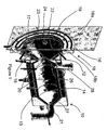
- Figure 1 is a partially sectional view of a reactor according to the invention
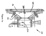
- Figure 1a is a side sectional view of a reactor according to the invention.
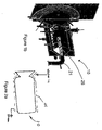
- FIG. 1b illustrates an alternate embodiment of the invention
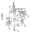
- Figure 2 is a schematic illustration of a system according to the invention.
- FIG. 2a illustrates a heat recovery embodiment of the invention
- Figure 3 illustrates temperatures and gas compositions for a sample run of a system according to the invention
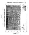
- Figure 4 illustrates a portion of concentrated solar radiation incorporated into the gas product in several sample runs of a system according to the invention
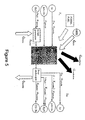
- Figure 5 further illustrates an energy balance of a system according to the invention
- Figure 6 illustrates temperature of the reactor and Inconel coating as a function of solar power input
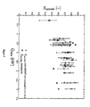
- Figure 7 illustrates calculated and measured petcoke conversion rates as a function of solar power input
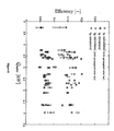
- Figure 8 illustrates process efficiency as a function of solar power input
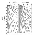
- Figure 9 illustrates molar flow rate curves for different petcoke feed rates and reactor volumes
- Figure 10 illustrates molar flow rate curves for different petcoke feed rates and solar power inputs.
- the process underlying the apparatus of the present invention and operation of same is described in co-pending and commonly owned US patent application serial number 10/954,507, filed September 29, 2004 .
- This application is incorporated herein in its entirety by reference.
- the process concerns the thermochemical conversion of carbonaceous materials, for example petroleum coke (petcoke), into synthetic fluid fuels, for example synthesis gas (syngas).
- the process uses an oxygen source, preferably steam, as a gasification agent.
- the process uses an external source of concentrated thermal radiation for supplying high-temperature process heat for the endothermic transformation.
- concentrated solar radiation is used as the source of process heat.
- the present invention offers a viable route for fossil fuel decarbonization and creates a transition path towards solar hydrogen.
- the advantages of supplying solar energy for process heat are four-fold: 1) the calorific value of the feedstock is upgraded; 2) the gaseous products are not contaminated by byproducts of combustion; 3) the discharge of pollutants to the environment is avoided; and 4) expenses due to combustion of fossil fuels and related investments for oxygen generation are substantially reduced.
- a 2 nd -Law analysis for generating electricity using the solar gasification products indicates a potential for doubling the specific electrical output and, consequently, halving the specific CO 2 emissions, vis-à-vis conventional petcoke-fired power plants.
- Feeds for the present invention are preferably any carbonaceous materials, preferably solid materials and/or slurries or other reactant streams containing same.
- Preferred material is particulate carbonaceous material, for example particles of petcoke as one non-limiting example. Such particles can preferably have an average diameter of between about 1 and about 1,000 microns, preferably less than about 100 microns.
- x and y are the elemental molar ratios of H/C and O/C in the carbonaceous feedstock, respectively.
- Sulfur compounds and other impurities contained in the raw materials are omitted from the above equation. These are of course important from a process standpoint, but their exclusion does not affect the main aspect of this invention.
- the moisture content is also not accounted for in the above Equation 1, but the stoichiometric addition of water can be adjusted accordingly.
- the net process is endothermic by about 50% of the feedstock's heating value, and proceeds at a temperature above 1350 K to produce a mixture of mainly H 2 and CO, as corroborated experimentally using a directly-irradiated fluidized bed reactor.
- the endothermicity and reaction temperature of the feedstock should be determined and used to optimize the process.
- the reaction temperature is preferably maintained at between about 1300 and about 1800 K.
- the present invention concerns a solar chemical reactor and method for carrying out the steam-gasification of carbonaceous solid materials using the reactor of the present invention.
- the reactor is described.
- Figure 1 shows a cylindrical cavity-reactor 10 that contains a radiation inlet 12 defined by a small opening or aperture to let concentrated radiation enter a cavity 14 defined by wall 13 of reactor 10.
- Figure 1 shows cavity 14 having a cylindrical form. It should be appreciated that other cavity geometries are possible, but cavity-type geometries are preferable because of their ability to capture incoming radiation effectively.
- the cavity can be defined by reactor wall 13 or other structure made out of suitable heat resistant materials, one example of which is InconelTM, a heat resistant metallic alloy provided by Inco Alloys International, Inc.
- the reactor walls can advantageously be provided with a ceramic liner such as a lining of Al 2 O 3 , or SiC, or other ceramic material.
- the reactor can be insulated as well, for example with a ceramic insulation such as ceramic foam, for example with Al 2 O 3 /ZrO 2 ceramic foam or the like.
- a radiation inlet chamber 15 is aligned with radiation inlet 12, and preferably has a first open end 17 connected with inlet 12 and a second open end 19. Ends 17, 19 are preferably defined at opposite ends of a cone shaped structure 22 which serves to further concentrate radiation passing along a converging flow path to inlet 12.
- a window 16, one preferred example of which is a clear fused quartz window, is positioned over open end 19. Window 16 is preferably mounted in a water-cooled ring 18 that also serves as a shield for spilled radiation. Ring 18 has two ring halves 18a, 18b, which in this embodiment clamp to both sides of window 16 to seal and hold window 16 in place. Ring half 18a is shown with a coolant tube 23 positioned along same. Tube 23 is communicated with a source of cooling fluid.
- Other window mounting arrangements are of course possible and well within the broad scope of the present invention.
- the radiation inlet chamber or passage 15 is preferably in the form of a converging flow structure, which converges in a radiation flow direction from a relatively larger flow area to a relatively smaller flow area. This structure is further discussed below.
- window 16 can be actively cooled and kept clear from particles and/or condensable gases.
- this is accomplished by defining an aerodynamic protection curtain created by tangential and radial flow through tangential and radial nozzles 24, 25 positioned in radiation inlet chamber 15 to create a desired flow pattern.
- Radial nozzles 25 are preferably substantially adjacent to window 16 while tangential nozzles 24 are preferably spaced inwardly from nozzles 25, and closer to radiation inlet 12. This serves to define a very stable vortex flow in radiation inlet chamber 15 which is effective to keep window 16 free of particles and other matter which could interfere with transmission of concentrated solar radiation, and also serves to help cool window 16 and prevent damage to same.
- Figure 1a further illustrates tangential nozzles 24 and radial nozzles 25 according to the invention.
- tangential nozzles 24 can be provided as bent or angled flow conduits which discharge fluid substantially tangential to an inside surface of radiation inlet chamber 15, and radial nozzles 25 can be defined by a ring gap in ring 18 which can be fed from an external source of purge gas, preferably steam.
- purge gas preferably steam
- a preferred gas for use in creating the protection flow is steam, which simplifies the apparatus and system since steam is already used as the source of oxygen for the reaction.
- steam is already used as the source of oxygen for the reaction.
- other configurations are possible within the scope of the invention, including the use of other fluids for generating the protective flow pattern and thereby protecting the window from deposition of particles and the like.
- a suitable alternative fluid is Argon.
- radiation inlet chamber 15 is defined in the shape of a frustum or cone 22 positioned between aperture 12 at one end and window 16/ring 18 at the other end.
- Cone 22 and especially the area around window 16 is preferably kept above a temperature of 373 K during operation so as to prevent steam condensation on window 16.
- the radiation inlet chamber defined by cone 22 can advantageously have a length selected to sufficiently concentrate the radiation as desired, and to focus this radiation upon the interior or cavity of reactor 10 as desired.
- Cone 22 is a particularly suitable embodiment because of the smooth converging inner walls defined by same. Of course, other structures would be suitable within the scope of the present invention.
- Figure 1 further shows cone 22 positioned to direct concentrated radiation along an axis A of reactor 10.
- radiation inlet or aperture 12 preferably has a size or area which is less than about 1/3 of the area of the inside surface of reactor 10. Radiation inlet chamber 15 is also preferably provided having a length which is sufficient to distance window 16 from reactor 10 and thereby to help protect window 16 from overheating due to the high temperatures within reactor 10.
- Inlets 24 and/or inlets 25 to radiation inlet chamber 15 are preferably axis-symmetrically distributed, that is, they are preferably positioned substantially equidistant from each other or at least from adjacent inlets, around a periphery of chamber 15.
- these inlets preferably include a set of tangential inlet ports or points 24 and a second set of radial inlet ports 25, each of which are preferably positioned in a separate plane, respectively, with the separate planes being axially spaced from each other.
- inlets 20 are also provided in reactor 10 to introduce steam or some other fluid medium, preferably a fluid source of oxygen, into reactor 10.
- Inlets 20 are preferably arranged substantially tangential to an inner surface so that flow through inlets 20 generates a helical or vortex flow through reactor 10 as desired.
- Inlets 20 can likewise be arranged in two or more groups, preferably axially spaced from each other.
- a particle feeding inlet 28 is also preferably provided for introducing particles to be treated into reactor 10.
- Particle feeding inlet 28 is preferably positioned substantially co-planar with one group of inlets 20 so as to encourage entrainment of particles fed to reactor 10 through inlet 28 in the fluid flow vortex created by flow through inlets 20.
- reactor 10 can preferably be provided having end walls 26, 27, which are themselves substantially cone shaped as shown. End wall 26 extends at an angle from aperture 12 to the full diameter of wall 13 of reactor 10, and end wall 27 extends at an angle from wall 13 of reactor 10 to the smaller diameter outlet 21 from reactor 10.
- Figure 1 shows outlet 21 arranged substantially coaxial with reactor 10. This is advantageous, particularly where a reaction does not go to completion and some particles exit the reactor.
- Figure 1b shows an alternate embodiment wherein an axial outlet tube 25 is positioned inside reactor 10 and along an axis thereof.
- tube 25 can be positioned along an axis A of reactor 10, and can have both ends open.
- Such a configuration can function as a "cyclone separator" and separate unreacted particles from produced syngas. In this way, unreacted particles will remain in reactor 10 until gasified.
- Figure 2 shows reactor 10 receiving concentrated solar energy, and also connected to a steam generator 30 for providing the fluid stream of oxygen source material.
- Reactor 10 is also connected to a coke feeder 32 for providing the carbonaceous solid material to be converted, a reactor cooling system 34 for providing coolant to tube 23 to cool cone 22 and window 16, and a window purge unit 36 for assisting in keeping window 16 clear of particles and the like as described above.
- control system 38 which is programmed to control feed of reactants to reactor 10, properly control the cooling and purge functions, and the like.
- Products from reactor 10 are conveyed through a filter 40 as well as any other post processing equipment, and then to a vent 42 to other processing and/or storage.
- control unit 38 advantageously is also connected to sensors 44 along a line to vent 42 for monitoring qualities of the product.
- particles of carbonaceous solid material and steam are injected into the reactor cavity 14 (Figure 1) either as a slurry or separately.
- steam and particles are injected separately, permitting separate control of mass flow rates and stoichiometry.
- Steam is introduced through several inlets 20 as shown, and may also be introduced into radiation inlet chamber 15 through inlets 24.
- suitable flow patterns in terms of residence time and flow stability are obtained with two sets of symmetrically distributed tangential nozzles 20, as shown in Figure 1. These sets can advantageously be positioned in a plurality, preferably two, planes drawn normal to the axis A of reactor 10.
- planes can be spaced as appropriate along the axis of the reactor, and advantageously serve to define the desired helical flow pattern of steam with entrained particles through the reactor.
- the different planes of steam injection inlets can be fed uniformly or, preferably, the set of inlets which is closer to aperture 12 can be the primary injection location and can be fed with a greater flow rate than planes of inlets located further downstream along axis A.
- particle-feeding unit 28 is shown positioned on the top of the reactor vessel 10 with an inlet port preferably located in the same plane as the primary steam injection system, allowing for immediate entrainment of particles by the steam flow.
- the gas-particle stream forms a vortex flow that progresses towards the rear along a helical path.
- the particles are directly exposed to high-flux irradiation, providing efficient heat transfer directly to the reaction site, and bypassing the limitations imposed by indirect heat transfer through reactor walls.
- Energy is absorbed by the reactants and raises their temperature to above about 1300K and drives the gasification reaction. Reaction products exit through outlet tube 21 at the rear side of the cavity.
- reaction products when reactor 10 is operated according to the invention, are produced in the form of a substantially equimolar mixture of hydrogen and carbon monoxide, with less than about 5% volume of carbon dioxide, as desired.
- the source of radiation is preferably concentrated solar energy.
- concentrated solar energy can be created using carious methods and apparatus known to a person of skill in the art.
- the structure of the present invention is particularly preferred as this structure is particularly effective at delivering concentrated solar energy to reactor 10 for carrying out the inventive process.
- an alternate embodiment of the invention uses a hybrid of concentrated solar energy and fossil fuel generated energy to provide the external radiation.
- the hydrocarbon material to be reacted can advantageously be a combination of particulate carbonaceous material such as petcoke, and a fossil fuel.
- the fossil fuel serves both to absorb external radiation as desired and also acts as a source of chemical reactants.
- the source of oxygen can advantageously be any of a wide variety of oxygen sources, such as steam, elemental oxygen, metal oxides and the like, and combinations thereof. While any of these can be utilized according to the invention, steam is particularly suitable for use in accordance with the present invention. The following description will be given using steam as the oxygen source.
- Figure 2a schematically illustrates an alternate embodiment of the invention wherein waste heat and/or spilled radiation are used to heat water to make steam, for example at inlets 20, 24, 25.
- Figure 2a schematically illustrates coil 44 or other heat exchange structure positioned to exchange heat with reactor 10 and/or cone22. Coil 44 can be fed with water from any suitable source, and spilled radiation from cone 22 and/or heat from reactor 10 and/or cone 22 heat this water to steam which can then be fed directly to inlets 20, 24 and/or 25 to meet some or all steam needs of reactor 10.
- Fig. 5 shows an energy balance for a system according to the invention and will be discussed further below.
- Fig. 5 schematically illustrates the reactor and shows concentrated radiation to the reactor.
- this concentrated radiation is preferably concentrated solar radiation as shown in solid lines in Fig. 5.
- concentrated radiation can be supplemented using fossil fuels as illustrated in dashed lines in Fig. 5.
- the source of concentrated radiation was a 120 square meter sun-tracking heliostat having an 8.5 m diameter parabaloid concentrator, and this delivers up to 40 kW at peak concentration ratios exceeding 5,000 suns.
- a Venetian blind type shutter located between the heliostat and the concentrator controls power input to the reactor.
- Radiative solar flux intensities were measured optically with a calibrated CCD camera by recording the image of the sun on a water-cooled alumina coated Lambertian (diffusively reflecting) plate positioned at the focal plane.
- the reactor was positioned with its aperture at the focal plane and intercepting the regions of maximum solar flux intensity. Integration of the incident radiative flux over the reactor's aperture yielded the solar power input, referred to as Q solar .
- Reactor wall temperatures were measured in twelve locations with type K thermocouples, inserted into the Inconel walls and not exposed to direct irradiation.
- the nominal cavity temperature was measured with a solar-blind pyrometer that is not affected by the reflected solar irradiation because it measures in a narrow wavelength interval around 1.39 microns where solar irradiation is mostly absorbed by the atmosphere.
- Gas flows were controlled using Bronkhorst HI-TEC electronic flow controllers.
- the coke-feeding ratio was determined by measuring the weight difference of the particle conveyor, with 5% accuracy.
- the reactor's pressure was monitored with pressure transducers, while a pressure safety valve prevented overpressure derived from a five-fold volumetric growth due to gas formation and thermal expansion.
- gaseous products were analyzed on-line by gas chromotagraphy (GC, High speed Micro GC G2890A by Agilent Technologies, equipped with a molecular sieve 5A and HaySep A capillary columns). Gas analysis was supplemented by IR-based detector for H 2 (Calomet-6 by Siemens). Representative solid product samples collected at the filter downstream of the reactor were examined by scanning electron micrography.
- GC gas chromotagraphy
- a solar reactor prototype based on the aforementioned concept was tested in a high-flux solar furnace for a solar power input in the range 3.3-6.6 kW, a nominal reactor temperature in the range 1296-1818 K, and a reactant mass flow rate in the range of 1.85-4.45 gr petcoke/min and 3.68-9.04 gr steam/min.
- chemical conversions of petcoke and steam reached up to 87% and 69% molar, respectively.
- Fig. 3 Temperatures and gas compositions for a representative solar run (run # 7) are shown in Fig. 3.
- Q heating and Q chem are supplied for heating the reactants to T reactor and for the enthalpy change of the reaction, respectively: Equation 7 :
- Q heating ⁇ H 2 O ⁇ n petcoke ⁇ ⁇ T steam T reactor c p , H 2 O ( g ) ( T ) ⁇ d T + ⁇ Ar ⁇ n petcoke ⁇ ⁇ T ⁇ T reactor c p , Ar ( g ) ( T ) ⁇ d T + n petcoke ⁇ ⁇ T ⁇ T reactor c p , petcoke ( T ) ⁇ d T Equation 8
- Q chem X petcoke ⁇ n petcoke ⁇ ⁇ H
- Q sensible n H 2 ⁇ ⁇ T h x T reactor c p , H 2 ( g ) ( T ) ⁇ d T + n C O ⁇ ⁇ T h x T reactor c p , C O ( g ) ( T ) ⁇ d T + n C O 2 ⁇ ⁇ T h x T reactor c p , C O 2 ( g ) ( T ) ⁇ d T + n C H 4 ⁇ ⁇ T h x T reactor c p , C H 4 ( g ) ( T ) ⁇ d T + ( 1 ⁇ X H 2 O ) ⁇ n H 2 O ⁇ ⁇ T h x T reactor c p , H 2 O ( g ) ( T ) ⁇ d T + n Ar ⁇ ⁇ T
- Q conduction is the power lost by conduction through the insulation, calculated using the thermal conductivities specified by the manufacturer and accounting for heat conduction bridges. Specific heats are known.
- Q reradiation is the power lost by re-radiation through the windowed aperture. It is composed by the reflected, emitted, and transmitted terms: Equation 10
- Q reradiation A aperture ⁇ ( q reflected + q emitted + q transmitted )
- Equation 11 Q solar A aperture ⁇ 0 ⁇ e ⁇ b ( T sun ) ⁇ R w ( ⁇ , T sun ) ⁇ d ⁇ ⁇ 0 ⁇ e ⁇ b ( T sun ) ⁇ d ⁇ Equation 12
- q emitted 1 2 ( Q solar A aperture ⁇ 0 ⁇ e ⁇ b ( T sun ) ⁇ A w ( ⁇ , T sun ) ⁇ d ⁇ ⁇ 0 ⁇ e ⁇ b ( T sun ) ⁇
- Equation (12) takes into account emission from both sides of the window.
- Aw, Tw and Rw are the overall spectral absorptance, transmittance, and reflectance, respectively, which, for clear fused quartz of high purity, are approximated to be constant in the three spectral bands shown in Table 6.
- Fcavity-window Aaperture/Acavity.
- n ( t ) n petcoke ⁇ ( ⁇ Ar + ⁇ H 2 O + X ( t ) ) ⁇ n petcoke ⁇ ( ⁇ Ar + ⁇ H 2 O + 1 ⁇ e ⁇ ln ( 1 ⁇ X potcoke ) ⁇ ⁇ t )
- Equation (20) Since all terms in Equation (20) are temperature dependent, the problem is solved iteratively until convergence in T reactor .
- the simulation model is run for the operational parameters of each experimental run listed in Table 2.
- Figures 6, 7, and 8 show the experimentally measured and numerically calculated values for reactor temperatures T reactor , petcoke conversion X petcoke , and energy conversion efficiencies ⁇ 1 and ⁇ 2, respectively.
- the error bars denote the error propagation in the calculated values derived from measurement errors in the solar power input Q solar and the petcoke feeding rate m petcoke . The agreement is within the error bars.
- the simulation model is further applied for determining optimal design parameters for maximum energy conversion efficiency. For example, a lower petcoke feeding rate leads to a higher chemical conversion due to longer residence times, but at the expense of a lower net solar energy absorbed. In contrast, a higher petcoke feeding rate leads to a larger portion of energy used for heating the feedstock but not converted into chemical energy. A similar effect has an increase in the reactor volume, resulting in longer residence times and higher chemical conversion, but at the expense of higher conduction losses.
- the selected input parameters are: the solar power input Q solar , the petcoke feeding rate mpetcoke, the overall thermal conductivity U, and the H 2 O-to-petcoke and Ar-to-petcoke molar ratios ⁇ H2O and ⁇ Ar .
- the output terms of interest are: T reactor , X petcoke , ⁇ 1, and ⁇ 2.
- Figure 9 shows a contour plot of the efficiencies ⁇ 1 and ⁇ 2 as a function of the reactor volume V and the petcoke feeding rate m petcoke , using as baseline the operating conditions of run # 7 listed in Table 2.
- Fig. 10 The effect of scaling-up the reactor is elucidated in Fig. 10, where ⁇ 1 and ⁇ 2 are plotted as a function of Q solar and m petcoke , using as baseline the optimum operating conditions found in Figure 9.
- the reactor volume is scaled-up linearly with Q solar while the aperture's diameter is adjusted to keep a constant average solar concentration ratio of 2300 suns. Further assumed is an improved 5 cm-thick ceramic insulation.
- the predicted ⁇ 1 of a 10, 100, and 1000 kW reactor is 12%, 21%, and 23%, respectively, whereas the predicted ⁇ 2 is 35%, 58%, and 63%, respectively.
- Tables 4 and 5 below provide Arrhenius parameters for steam-gasification of flexicoke and PD coke, respectively.
- Table 4 Reaction constant 1070 - 1370 K Flexicoke E A [kJ/mol] k 0 [k i ] RMS [-] k 1 [mol/(g s Pa)] 158 4.74 ⁇ 10 -3 4.22 ⁇ 10 -10 k 2 [mol/(g s Pa)] 66.5 1.02 ⁇ 10 -6 5.58 ⁇ 10 -10 k 3 [1/Pa] -200 1.09 ⁇ 10 -12 5.05 ⁇ 10 -04
- Table 5 Reaction constant 1070 - 1670 K PD Coke E A [kJ/mol] k 0 [k i ] RMS [-] k 1 [mol/(g s Pa)] 78.9 1.05 ⁇ 10 -6 3.62 ⁇ 10 -10 k 2 [mol/(g s Pa)] 91.5 1.94 ⁇ 10 -6 3.30 ⁇ 10 -10 k 3 [1/Pa] -
- a solar chemical reactor for performing solar steam-gasification of petcoke to syngas.
- Example data was obtained using a high-flux solar furnace for a solar power input in the range 3.3-6.6 kW, a nominal reactor temperatures in the range 1296-1818 K, and a reactant mass flow rate in the range of 1.85-4.45 gr petcoke/min and 3.68-9.04 gr steam/min.
- Chemical conversions of petcoke and steam reached up to 87% and 69%, respectively.
- the energy conversion efficiency defined as the portion of solar energy net absorbed (both as chemical energy and sensible heat) ranged from 10 to 20%.
- the steady state energy conservation equation that links the radiative power input with the power consumed by the endothermic chemical reaction was determined. Validation was accomplished by comparing calculated and measured values for temperatures, chemical conversions, and energy conversion efficiencies. Example results predict a solar-to-chemical energy conversion efficiency of 63% and a petcoke gasification rate of 76 kg/h for a solar power input of 1 MW to a scaled-up reactor.
Landscapes
- Chemical & Material Sciences (AREA)
- Engineering & Computer Science (AREA)
- Oil, Petroleum & Natural Gas (AREA)
- Organic Chemistry (AREA)
- Combustion & Propulsion (AREA)
- Life Sciences & Earth Sciences (AREA)
- General Chemical & Material Sciences (AREA)
- Chemical Kinetics & Catalysis (AREA)
- Wood Science & Technology (AREA)
- Sustainable Energy (AREA)
- General Engineering & Computer Science (AREA)
- Mechanical Engineering (AREA)
- Thermal Sciences (AREA)
- Physics & Mathematics (AREA)
- Sustainable Development (AREA)
- Physical Or Chemical Processes And Apparatus (AREA)
Applications Claiming Priority (2)
| Application Number | Priority Date | Filing Date | Title |
|---|---|---|---|
| US65980705P | 2005-03-08 | 2005-03-08 | |
| US11/369,517 US7449158B2 (en) | 2003-10-01 | 2006-03-06 | Apparatus and gasification of carbonaceous solid materials |
Publications (1)
| Publication Number | Publication Date |
|---|---|
| EP1700901A1 true EP1700901A1 (de) | 2006-09-13 |
Family
ID=36337393
Family Applications (1)
| Application Number | Title | Priority Date | Filing Date |
|---|---|---|---|
| EP06004671A Withdrawn EP1700901A1 (de) | 2005-03-08 | 2006-03-08 | Vorrichtung zur Vergasung von Kohlenfeststoffen |
Country Status (2)
| Country | Link |
|---|---|
| US (2) | US7449158B2 (de) |
| EP (1) | EP1700901A1 (de) |
Cited By (2)
| Publication number | Priority date | Publication date | Assignee | Title |
|---|---|---|---|---|
| WO2011092456A1 (en) * | 2010-01-27 | 2011-08-04 | Rifat Ai Chalabi | Improvements in thermal oxidisers, using concentrated sunlight |
| WO2012033475A1 (ru) * | 2010-09-09 | 2012-03-15 | Tsyhankov Ivan Yurjevich | Генератор для выработки синтезированного газа |
Families Citing this family (32)
| Publication number | Priority date | Publication date | Assignee | Title |
|---|---|---|---|---|
| WO2009012190A1 (en) * | 2007-07-15 | 2009-01-22 | Yin Wang | Wood-drying solar greenhouse |
| AT505927B1 (de) * | 2007-12-21 | 2009-05-15 | Holcim Technology Ltd | Verfahren zum verbessern der produkteigenschaften von klinker beim brennen von rohmehl |
| US9188086B2 (en) | 2008-01-07 | 2015-11-17 | Mcalister Technologies, Llc | Coupled thermochemical reactors and engines, and associated systems and methods |
| US8318131B2 (en) | 2008-01-07 | 2012-11-27 | Mcalister Technologies, Llc | Chemical processes and reactors for efficiently producing hydrogen fuels and structural materials, and associated systems and methods |
| US8931475B2 (en) * | 2008-07-10 | 2015-01-13 | Brightsource Industries (Israel) Ltd. | Systems and methods for control of a solar power tower using infrared thermography |
| US8318269B2 (en) * | 2009-02-17 | 2012-11-27 | Mcalister Technologies, Llc | Induction for thermochemical processes, and associated systems and methods |
| US8441361B2 (en) | 2010-02-13 | 2013-05-14 | Mcallister Technologies, Llc | Methods and apparatuses for detection of properties of fluid conveyance systems |
| WO2010103520A1 (en) * | 2009-03-10 | 2010-09-16 | Boaz Zadik | Solar powered method and system for sludge treatment |
| US8814961B2 (en) | 2009-06-09 | 2014-08-26 | Sundrop Fuels, Inc. | Various methods and apparatuses for a radiant-heat driven chemical reactor |
| US9663363B2 (en) | 2009-06-09 | 2017-05-30 | Sundrop Fuels, Inc. | Various methods and apparatuses for multi-stage synthesis gas generation |
| US20100242354A1 (en) * | 2009-06-09 | 2010-09-30 | Sundrop Fuels, Inc. | Systems and methods for reactor chemistry and control |
| US8187549B2 (en) * | 2010-02-13 | 2012-05-29 | Mcalister Technologies, Llc | Chemical reactors with annularly positioned delivery and removal devices, and associated systems and methods |
| KR101297906B1 (ko) | 2010-02-13 | 2013-08-22 | 맥알리스터 테크놀로지즈 엘엘씨 | 수소계 연료 및 구조적 성분을 생성하기 위한 압력 및 열전달 특성을 갖는 반응기 용기와,관련 시스템 및 방법 |
| JP5726911B2 (ja) | 2010-02-13 | 2015-06-03 | マクアリスター テクノロジーズ エルエルシー | 水素ベースの燃料および構造要素を生成する透過面を有する反応容器、ならびに関連するシステムおよび方法 |
| CN102985195B (zh) | 2010-06-08 | 2016-01-27 | 三照普燃料公司 | 用于超高热通量化学反应器的各种方法和装置 |
| WO2012083097A2 (en) * | 2010-12-17 | 2012-06-21 | University Of Delaware | Beam-down solar-thermochemical reactor for the ultra-high temperature dissociation of solid-oxides and creation of solar fuels and materials and methods of use thereof |
| US8826657B2 (en) | 2011-08-12 | 2014-09-09 | Mcallister Technologies, Llc | Systems and methods for providing supplemental aqueous thermal energy |
| US9522379B2 (en) | 2011-08-12 | 2016-12-20 | Mcalister Technologies, Llc | Reducing and/or harvesting drag energy from transport vehicles, including for chemical reactors, and associated systems and methods |
| US8669014B2 (en) | 2011-08-12 | 2014-03-11 | Mcalister Technologies, Llc | Fuel-cell systems operable in multiple modes for variable processing of feedstock materials and associated devices, systems, and methods |
| WO2013025647A2 (en) | 2011-08-12 | 2013-02-21 | Mcalister Technologies, Llc | Fuel-cell systems operable in multiple modes for variable processing of feedstock materials and associated devices, systems, and methods |
| US8911703B2 (en) | 2011-08-12 | 2014-12-16 | Mcalister Technologies, Llc | Reducing and/or harvesting drag energy from transport vehicles, including for chemical reactors, and associated systems and methods |
| CN103857873A (zh) | 2011-08-12 | 2014-06-11 | 麦卡利斯特技术有限责任公司 | 从水下来源除去和处理气体的系统和方法 |
| WO2013025645A2 (en) | 2011-08-12 | 2013-02-21 | Mcalister Technologies, Llc | Systems and methods for collecting and processing permafrost gases, and for cooling permafrost |
| US8821602B2 (en) | 2011-08-12 | 2014-09-02 | Mcalister Technologies, Llc | Systems and methods for providing supplemental aqueous thermal energy |
| WO2013025650A1 (en) | 2011-08-12 | 2013-02-21 | Mcalister Technologies, Llc | Mobile transport platforms for producing hydrogen and structural materials and associated systems and methods |
| US8888408B2 (en) | 2011-08-12 | 2014-11-18 | Mcalister Technologies, Llc | Systems and methods for collecting and processing permafrost gases, and for cooling permafrost |
| US8734546B2 (en) | 2011-08-12 | 2014-05-27 | Mcalister Technologies, Llc | Geothermal energization of a non-combustion chemical reactor and associated systems and methods |
| US9295961B2 (en) | 2012-03-26 | 2016-03-29 | Sundrop Fuels, Inc. | Various methods and apparatuses for internally heated radiant tubes in a chemical reactor |
| US8926719B2 (en) | 2013-03-14 | 2015-01-06 | Mcalister Technologies, Llc | Method and apparatus for generating hydrogen from metal |
| US9829217B2 (en) | 2013-04-22 | 2017-11-28 | The Babcock & Wilcox Company | Concentrated solar power solids-based system |
| WO2017024338A1 (en) * | 2015-08-13 | 2017-02-16 | The University Of Adelaide | Solar receiver |
| FR3103259B1 (fr) * | 2019-11-14 | 2022-07-15 | Commissariat A L Energie Atomique Et Aux Energies Alternatives | Réacteur solaire à jet à transfert thermique amélioré. Procédé de fonctionnement associé, application à la gazéification de biomasse ou au reformage. |
Citations (7)
| Publication number | Priority date | Publication date | Assignee | Title |
|---|---|---|---|---|
| US4229184A (en) * | 1979-04-13 | 1980-10-21 | The United States Of America As Represented By The United States Department Of Energy | Apparatus and method for solar coal gasification |
| US4290779A (en) * | 1980-05-15 | 1981-09-22 | Nasa | Solar heated fluidized bed gasification system |
| GB2073869A (en) * | 1980-04-15 | 1981-10-21 | Us Energy | Solar heated gasification apparatus |
| FR2503177A1 (fr) * | 1981-03-31 | 1982-10-08 | Bergwerksverband Gmbh | Procede de production de gaz contenant h2 et co, notamment a partir de charbon ou de coke |
| US4415339A (en) * | 1981-04-06 | 1983-11-15 | The United States Of America As Represented By The Department Of Energy | Solar coal gasification reactor with pyrolysis gas recycle |
| US5647877A (en) * | 1991-12-26 | 1997-07-15 | Yeda Research And Development Company Limited | Solar energy gasification of solid carbonaceous material in liquid dispersion |
| EP1520901A1 (de) * | 2003-10-01 | 2005-04-06 | Intevep SA | Verfahren zur Umwandlung von schweren Rohölen und Petrolkoks unter Verwendung einer externen Strahlungsquelle |
Family Cites Families (22)
| Publication number | Priority date | Publication date | Assignee | Title |
|---|---|---|---|---|
| US2760920A (en) * | 1952-06-06 | 1956-08-28 | Robert B Olsen | Solar energy coking apparatus |
| US4059416A (en) * | 1972-07-13 | 1977-11-22 | Thagard Technology Company | Chemical reaction process utilizing fluid-wall reactors |
| US3928000A (en) * | 1973-12-28 | 1975-12-23 | Texaco Inc | Production of a clean methane-rich fuel gas from high-sulfur containing hydrocarbonaceous materials |
| US3993458A (en) * | 1975-03-28 | 1976-11-23 | The United States Of America As Represented By The United States Energy Research And Development Administration | Method for producing synthetic fuels from solid waste |
| US4000733A (en) * | 1975-10-31 | 1977-01-04 | Lou Allen Pauly | Solar furnace |
| CH609089A5 (de) * | 1976-04-22 | 1979-02-15 | Willy Keller | |
| US4177120A (en) * | 1977-04-29 | 1979-12-04 | Solarco Corporation | Photolytic process for gasification of carbonaceous material |
| US4455153A (en) * | 1978-05-05 | 1984-06-19 | Jakahi Douglas Y | Apparatus for storing solar energy in synthetic fuels |
| US4588478A (en) * | 1983-09-15 | 1986-05-13 | Phillips Petroleum Company | Apparatus for solar retorting of oil shale |
| DE3337078A1 (de) * | 1983-10-12 | 1985-05-02 | M.A.N. Maschinenfabrik Augsburg-Nürnberg AG, 8000 München | Verfahren und vorrichtung zum herstellen von synthesegas |
| US4582590A (en) * | 1984-07-23 | 1986-04-15 | The Unied States Of America As Represented By The Administrator, National Aeronautics And Space Administration | Solar heated oil shale pyrolysis process |
| US5247796A (en) * | 1985-12-27 | 1993-09-28 | Parker Robin Z | Solar augmented power system |
| US5236470A (en) * | 1989-04-04 | 1993-08-17 | Advanced Waste Treatment Technology, Inc. | Method for the gasification of coal and other carbonaceous material |
| US5934271A (en) * | 1994-07-19 | 1999-08-10 | Anutech Pty Limited | Large aperture solar collectors with improved stability |
| US6233914B1 (en) * | 1997-07-31 | 2001-05-22 | Ormat Industries Ltd. | Method of an apparatus for producing power having a solar reformer and a steam generator which generate fuel for a power plant |
| US6187465B1 (en) * | 1997-11-07 | 2001-02-13 | Terry R. Galloway | Process and system for converting carbonaceous feedstocks into energy without greenhouse gas emissions |
| US6510695B1 (en) * | 1999-06-21 | 2003-01-28 | Ormat Industries Ltd. | Method of and apparatus for producing power |
| IL131371A0 (en) * | 1999-08-12 | 2001-01-28 | Yeda Res & Dev | Reaction chamber with a protected surface |
| US7033570B2 (en) * | 2000-05-08 | 2006-04-25 | Regents Of The University Of Colorado | Solar-thermal fluid-wall reaction processing |
| WO2003049853A1 (en) * | 2000-05-08 | 2003-06-19 | Midwest Research Institute | Solar thermal aerosol flow reaction process |
| US6384320B1 (en) * | 2000-10-13 | 2002-05-07 | Leon Lung-Chen Chen | Solar compound concentrator of electric power generation system for residential homes |
| US6832485B2 (en) * | 2001-11-26 | 2004-12-21 | Ormat Industries Ltd. | Method of and apparatus for producing power using a reformer and gas turbine unit |
-
2006
- 2006-03-06 US US11/369,517 patent/US7449158B2/en not_active Expired - Fee Related
- 2006-03-08 EP EP06004671A patent/EP1700901A1/de not_active Withdrawn
-
2008
- 2008-01-22 US US12/017,426 patent/US8257454B1/en not_active Expired - Fee Related
Patent Citations (8)
| Publication number | Priority date | Publication date | Assignee | Title |
|---|---|---|---|---|
| US4229184A (en) * | 1979-04-13 | 1980-10-21 | The United States Of America As Represented By The United States Department Of Energy | Apparatus and method for solar coal gasification |
| GB2073869A (en) * | 1980-04-15 | 1981-10-21 | Us Energy | Solar heated gasification apparatus |
| US4290779A (en) * | 1980-05-15 | 1981-09-22 | Nasa | Solar heated fluidized bed gasification system |
| FR2503177A1 (fr) * | 1981-03-31 | 1982-10-08 | Bergwerksverband Gmbh | Procede de production de gaz contenant h2 et co, notamment a partir de charbon ou de coke |
| US4415339A (en) * | 1981-04-06 | 1983-11-15 | The United States Of America As Represented By The Department Of Energy | Solar coal gasification reactor with pyrolysis gas recycle |
| US5647877A (en) * | 1991-12-26 | 1997-07-15 | Yeda Research And Development Company Limited | Solar energy gasification of solid carbonaceous material in liquid dispersion |
| EP1520901A1 (de) * | 2003-10-01 | 2005-04-06 | Intevep SA | Verfahren zur Umwandlung von schweren Rohölen und Petrolkoks unter Verwendung einer externen Strahlungsquelle |
| US20050192362A1 (en) | 2003-10-01 | 2005-09-01 | Domingo Rodriguez | Process for converting heavy crude oils and petroleum coke to syngas using external source of radiation |
Cited By (4)
| Publication number | Priority date | Publication date | Assignee | Title |
|---|---|---|---|---|
| WO2011092456A1 (en) * | 2010-01-27 | 2011-08-04 | Rifat Ai Chalabi | Improvements in thermal oxidisers, using concentrated sunlight |
| CN102821834A (zh) * | 2010-01-27 | 2012-12-12 | 勒法特·埃尔·查勒比 | 使用聚集的太阳光的热氧化器的改进 |
| CN102821834B (zh) * | 2010-01-27 | 2014-08-13 | 勒法特·埃尔·查勒比 | 使用聚集的太阳光的热氧化器的改进 |
| WO2012033475A1 (ru) * | 2010-09-09 | 2012-03-15 | Tsyhankov Ivan Yurjevich | Генератор для выработки синтезированного газа |
Also Published As
| Publication number | Publication date |
|---|---|
| US7449158B2 (en) | 2008-11-11 |
| US20070098602A1 (en) | 2007-05-03 |
| US20120222355A1 (en) | 2012-09-06 |
| US8257454B1 (en) | 2012-09-04 |
Similar Documents
| Publication | Publication Date | Title |
|---|---|---|
| US8257454B1 (en) | Method for gasification of carbonaceous solid materials | |
| Z’Graggen et al. | Hydrogen production by steam-gasification of petroleum coke using concentrated solar power—II Reactor design, testing, and modeling | |
| Hirsch et al. | Solar hydrogen production by thermal decomposition of natural gas using a vortex-flow reactor | |
| Curcio et al. | Dynamic simulation of a solar-autothermal hybridized gasifier: Model principle, experimental validation and parametric study | |
| Maag et al. | Solar thermal cracking of methane in a particle-flow reactor for the co-production of hydrogen and carbon | |
| Z’Graggen et al. | Hydrogen production by steam-gasification of petroleum coke using concentrated solar power—III. Reactor experimentation with slurry feeding | |
| AU2007289219B2 (en) | Rapid solar-thermal conversion of biomass to syngas | |
| Rodat et al. | Hydrogen production from solar thermal dissociation of natural gas: development of a 10 kW solar chemical reactor prototype | |
| Steinfeld et al. | A solar chemical reactor for co-production of zinc and synthesis gas | |
| US6872378B2 (en) | Solar thermal aerosol flow reaction process | |
| AU2010355257B2 (en) | Various methods and apparatuses for an ultra-high heat flux chemical reactor | |
| US8673035B2 (en) | Solar-thermal reaction processing | |
| Abanades et al. | A drop-tube particle-entrained flow solar reactor applied to thermal methane splitting for hydrogen production | |
| Z'Graggen et al. | Hydrogen production by steam-gasification of carbonaceous materials using concentrated solar energy–V. Reactor modeling, optimization, and scale-up | |
| Abanades et al. | Hydrogen production from solar thermal dissociation of methane in a high-temperature fluid-wall chemical reactor | |
| EP1520901B1 (de) | Verfahren zur Umwandlung von schweren Rohölen und Petrolkoks unter Verwendung einer externen Strahlungsquelle | |
| US20100247387A1 (en) | Systems and methods for biomass gasifier reactor and receiver configuration | |
| Chuayboon et al. | Solar chemical looping gasification of biomass with the ZnO/Zn redox system for syngas and zinc production in a continuously-fed solar reactor | |
| Z’Graggen et al. | Hydrogen production by steam-gasification of carbonaceous materials using concentrated solar energy—IV. Reactor experimentation with vacuum residue | |
| Nikulshina et al. | Coproduction of syngas and lime by combined CaCO3-calcination and CH4-reforming using a particle-flow reactor driven by concentrated solar radiation | |
| Maag et al. | Design of a 10 MW particle-flow reactor for syngas production by steam-gasification of carbonaceous feedstock using concentrated solar energy | |
| US12474088B2 (en) | Receiver | |
| Liu et al. | A comprehensive experimental study of the solar-driven biomass gasification under CO2 atmosphere in a combined drop-tube and fixed-bed reactor | |
| Z’Graggen et al. | Hydrogen production by steam-gasification of petroleum coke using concentrated solar power: reactor experimentation with slurry feeding | |
| Z'Graggen | Solar Gasification of Carbonaceous Materials: Reactor Design, Modeling, and Experimentation |
Legal Events
| Date | Code | Title | Description |
|---|---|---|---|
| PUAI | Public reference made under article 153(3) epc to a published international application that has entered the european phase |
Free format text: ORIGINAL CODE: 0009012 |
|
| AK | Designated contracting states |
Kind code of ref document: A1 Designated state(s): AT BE BG CH CY CZ DE DK EE ES FI FR GB GR HU IE IS IT LI LT LU LV MC NL PL PT RO SE SI SK TR |
|
| AX | Request for extension of the european patent |
Extension state: AL BA HR MK YU |
|
| 17P | Request for examination filed |
Effective date: 20070220 |
|
| AKX | Designation fees paid |
Designated state(s): CH DE ES LI |
|
| 17Q | First examination report despatched |
Effective date: 20070704 |
|
| STAA | Information on the status of an ep patent application or granted ep patent |
Free format text: STATUS: THE APPLICATION IS DEEMED TO BE WITHDRAWN |
|
| 18D | Application deemed to be withdrawn |
Effective date: 20161001 |