EP1699566B1 - Spraying device with interchangeable cartridge - Google Patents
Spraying device with interchangeable cartridge Download PDFInfo
- Publication number
- EP1699566B1 EP1699566B1 EP04810535.7A EP04810535A EP1699566B1 EP 1699566 B1 EP1699566 B1 EP 1699566B1 EP 04810535 A EP04810535 A EP 04810535A EP 1699566 B1 EP1699566 B1 EP 1699566B1
- Authority
- EP
- European Patent Office
- Prior art keywords
- fluid
- cartridge
- valve
- spraying device
- sprayer body
- Prior art date
- Legal status (The legal status is an assumption and is not a legal conclusion. Google has not performed a legal analysis and makes no representation as to the accuracy of the status listed.)
- Expired - Lifetime
Links
Images




Classifications
-
- B—PERFORMING OPERATIONS; TRANSPORTING
- B05—SPRAYING OR ATOMISING IN GENERAL; APPLYING FLUENT MATERIALS TO SURFACES, IN GENERAL
- B05B—SPRAYING APPARATUS; ATOMISING APPARATUS; NOZZLES
- B05B7/00—Spraying apparatus for discharge of liquids or other fluent materials from two or more sources, e.g. of liquid and air, of powder and gas
- B05B7/02—Spray pistols; Apparatus for discharge
- B05B7/04—Spray pistols; Apparatus for discharge with arrangements for mixing liquids or other fluent materials before discharge
- B05B7/0408—Spray pistols; Apparatus for discharge with arrangements for mixing liquids or other fluent materials before discharge with arrangements for mixing two or more liquids
-
- B—PERFORMING OPERATIONS; TRANSPORTING
- B05—SPRAYING OR ATOMISING IN GENERAL; APPLYING FLUENT MATERIALS TO SURFACES, IN GENERAL
- B05B—SPRAYING APPARATUS; ATOMISING APPARATUS; NOZZLES
- B05B7/00—Spraying apparatus for discharge of liquids or other fluent materials from two or more sources, e.g. of liquid and air, of powder and gas
- B05B7/24—Spraying apparatus for discharge of liquids or other fluent materials from two or more sources, e.g. of liquid and air, of powder and gas with means, e.g. a container, for supplying liquid or other fluent material to a discharge device
- B05B7/2402—Apparatus to be carried on or by a person, e.g. by hand; Apparatus comprising containers fixed to the discharge device
- B05B7/244—Apparatus to be carried on or by a person, e.g. by hand; Apparatus comprising containers fixed to the discharge device using carrying liquid for feeding, e.g. by suction, pressure or dissolution, a carried liquid from the container to the nozzle
- B05B7/2443—Apparatus to be carried on or by a person, e.g. by hand; Apparatus comprising containers fixed to the discharge device using carrying liquid for feeding, e.g. by suction, pressure or dissolution, a carried liquid from the container to the nozzle the carried liquid and the main stream of carrying liquid being brought together downstream of the container before discharge
-
- B—PERFORMING OPERATIONS; TRANSPORTING
- B05—SPRAYING OR ATOMISING IN GENERAL; APPLYING FLUENT MATERIALS TO SURFACES, IN GENERAL
- B05B—SPRAYING APPARATUS; ATOMISING APPARATUS; NOZZLES
- B05B7/00—Spraying apparatus for discharge of liquids or other fluent materials from two or more sources, e.g. of liquid and air, of powder and gas
- B05B7/24—Spraying apparatus for discharge of liquids or other fluent materials from two or more sources, e.g. of liquid and air, of powder and gas with means, e.g. a container, for supplying liquid or other fluent material to a discharge device
- B05B7/2402—Apparatus to be carried on or by a person, e.g. by hand; Apparatus comprising containers fixed to the discharge device
- B05B7/2478—Gun with a container which, in normal use, is located above the gun
-
- B—PERFORMING OPERATIONS; TRANSPORTING
- B05—SPRAYING OR ATOMISING IN GENERAL; APPLYING FLUENT MATERIALS TO SURFACES, IN GENERAL
- B05B—SPRAYING APPARATUS; ATOMISING APPARATUS; NOZZLES
- B05B7/00—Spraying apparatus for discharge of liquids or other fluent materials from two or more sources, e.g. of liquid and air, of powder and gas
- B05B7/24—Spraying apparatus for discharge of liquids or other fluent materials from two or more sources, e.g. of liquid and air, of powder and gas with means, e.g. a container, for supplying liquid or other fluent material to a discharge device
- B05B7/2402—Apparatus to be carried on or by a person, e.g. by hand; Apparatus comprising containers fixed to the discharge device
- B05B7/2405—Apparatus to be carried on or by a person, e.g. by hand; Apparatus comprising containers fixed to the discharge device using an atomising fluid as carrying fluid for feeding, e.g. by suction or pressure, a carried liquid from the container to the nozzle
- B05B7/2408—Apparatus to be carried on or by a person, e.g. by hand; Apparatus comprising containers fixed to the discharge device using an atomising fluid as carrying fluid for feeding, e.g. by suction or pressure, a carried liquid from the container to the nozzle characterised by the container or its attachment means to the spray apparatus
-
- Y—GENERAL TAGGING OF NEW TECHNOLOGICAL DEVELOPMENTS; GENERAL TAGGING OF CROSS-SECTIONAL TECHNOLOGIES SPANNING OVER SEVERAL SECTIONS OF THE IPC; TECHNICAL SUBJECTS COVERED BY FORMER USPC CROSS-REFERENCE ART COLLECTIONS [XRACs] AND DIGESTS
- Y10—TECHNICAL SUBJECTS COVERED BY FORMER USPC
- Y10T—TECHNICAL SUBJECTS COVERED BY FORMER US CLASSIFICATION
- Y10T137/00—Fluid handling
- Y10T137/7722—Line condition change responsive valves
- Y10T137/7837—Direct response valves [i.e., check valve type]
Definitions
- the present invention relates to a spraying device and more particularly to a spraying device that includes a sprayer body, a cartridge containing a first fluid, the cartridge being oriented such that gravity exerts a downward force on the first fluid, and a valve for mixing a second fluid with the first fluid by creating a vacuum that draws the first fluid out of the cartridge, without the need for a dip tube, and into the valve thus enabling the first and second fluids to mix and be dispensed.
- Typical spraying devices include a sprayer body connected to a container filled with a fluid (e.g. , a concentrated chemical) and connected to a water hose. The fluids are mixed and dispensed via a spray head.
- Typical sprayers include a dip tube that extends downwardly into the container. The dip tube provides a direct passageway between the fluid in the container and the sprayer body. The constant flow of water through the sprayer produces a vacuum that draws the fluid through the dip tube, mixes the fluid with the water and dispenses the mixture from the spray head.
- Typical sprayers also include sealed containers for storing the fluid to be dispensed. These containers can only be used with a spraying device, they can not be used to manually dispense the contained fluid.
- a first fluid e.g. , water
- a second fluid e.g. , water
- US 2002/0175223 A1 is related to a device for adjusting discharge manner and flow amount of a fluid, and more particularly to a switch of a straight sprinkling gun or sprinkling gun provided with a brush at the discharge end, wherein the device includes a detergent chamber as well as a flow damper unit including a flow-guiding hole.
- the present invention overcomes the disadvantages of the prior art by providing a spraying device that includes a cartridge containing a first fluid, the cartridge being removably connected to a sprayer body.
- the cartridge is oriented such that gravity exerts a downward force on the first fluid.
- the sprayer body includes a conduit for receiving a second fluid.
- a valve is coupled to the conduit. The valve allows the second fluid to flow through the valve, thereby creating a Venturi vacuum that draws the first fluid out of the cartridge and into the valve to enable the first and second fluids to mix and form an outlet stream.
- An orifice meters a predetermined amount of the first fluid into the valve to achieve a predetermined ratio of the first fluid to the second fluid in the outlet stream. The outlet stream may then be dispensed from a spray nozzle.
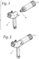
- a spraying device of the present invention generally includes two primary parts: a sprayer body 10 and a cartridge 12, as shown in FIGs. 1 and 2 .
- the cartridge 12 is removably connected to the sprayer body 10 via threads 24, or other suitable connecting means, as shown in FIGs. 1-3 .
- a first fluid 36 contained in the cartridge 12 flows into the sprayer body 10 and is mixed with a second fluid 37 (e.g. , water) in valve 20, as explained below.
- the cartridge 12 can be made of flexible plastic, or any other suitable material.
- the cartridge 12 can have many different shapes and forms, including a flexible bottle, pouch or bag shape. An alternative cartridge design is illustrated in FIG. 12 .
- the first fluid 36 may comprise liquid fertilizers, insecticides, herbicides, fungicides, mildewcides, nematicides, growth regulators, insect repellents, cleaning products, and the like.
- fluid conduit 17 is disposed in the sprayer body 10, which can be constructed from any suitable material, such as plastic.
- a first end of fluid conduit 17 is coupled to hose coupler 14.
- the sprayer body 10 connects to a typical home water supply (e.g. , a garden hose) at coupler 14.
- the coupler 14 includes an anti-siphon unit 16 (shown in FIG. 8 ), which is well known in the art, for preventing or minimizing back flow and leaking from fluid conduit 17.
- a second end of fluid conduit 17 is coupled to a valve 20, which is coupled to spray nozzle 48.
- the terms "connected” and “coupled” both mean connected directly or indirectly through intervening components.
- the valve 20 includes a valve knob 22 for rotatably selecting between three conditions: off, feed and water only.
- the valve 20 is coupled to and actuated by the valve knob 22.
- the valve 20 further includes a Venturi location 18 for creating a vacuum for siphoning the first fluid from the cartridge 12.
- the second fluid 37 e.g. , water
- the valve 20 flows into the valve 20 creating a Venturi vacuum that draws the first fluid 36 out of the cartridge 12.
- the flow of the second fluid 37 through the valve 20 creates a vacuum therein. Because the cartridge 12 is oriented such that gravity exerts a downward force on the first fluid 36, the valve 20 is able to draw the first fluid 36 out of the cartridge 12 without the need for a dip tube.
- the first fluid 36 travels through cartridge adapter 38 and filter assembly 40.
- the valve 20 includes a metering orifice 42 through which the first fluid flows into the valve 20 where it is mixed with the second fluid 37 at Venturi location 18. The mixture is then dispensed out of the spray nozzle 48.
- the spray nozzle 48 is rotatably adjustable to provide different spray patterns via three different nozzle orifices: flat 50, jet 52 and shower 54, as shown in FIG. 8 .
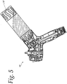
- FIG. 3 shows the spraying device in the "feed” position, which mixes the two fluids and dispenses the mixture.
- FIG. 4 shows the spraying device in the "water only” position, which dispenses the second fluid 37 only.
- FIG. 5 shows the spraying device in the "off" position, which prevents either fluid from being dispensed.
- the cartridge 12 includes a two-way check valve 30 that keeps the cartridge sealed until the vacuum generated by the sprayer body 10 actuates the "duckbill" portion 32, which allows the first fluid 36 to be siphoned from the cartridge 12. Air is allowed back into the cartridge 12 via the "umbrella” portion 34 thus allowing proper venting and consistent mixing of the first fluid 36 with the second fluid 37 in the valve 20. The second fluid 37 does not enter the cartridge 12 during this process.
- the check valve 30 allows the cartridge 12 to be removed from the sprayer body 10 at any time without leakage because the check valve 30 will return to a closed position when no vacuum is present.
- Another advantage of the cartridge 12 is that the first fluid can be manually dispensed from the cartridge 12 by squeezing the flexible cartridge 12 when it is in an inverted position. This allows a user to manually mix small quantities of the first fluid with a second fluid (e.g. , water) in a bucket or watering can without the use of the sprayer body 10. This allows the first fluid to be distributed in small areas without the need for a garden hose.
- Previously known cartridges are sealed containers that can only be used with a corresponding spraying device.
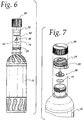
- the cartridge 12 includes a cap 26 having threads that correspond to the threads 24 on the cartridge 12, as shown in FIG. 6 .
- the cartridge 12 can be a sealed, non-refillable container, as shown in FIG. 6 or a refillable container that includes a secondary threaded closure 28, as shown in FIG. 7 .
- fixed fluid metering is accomplished by including a metering orifice 70 within cartridge insert 72, as shown in FIG. 9 .
- the metering orifice 70 is included in the secondary threaded closure 28, as shown in FIG. 7 .
- cartridges containing different types of fluids can each have appropriately sized orifices to mix the proper ratio of the first fluid 36 with the second fluid 37. Providing the metering orifice within the cartridge 12 eliminates having to make or use different sprayers for different types of fluids.
- Variable fluid metering is accomplished by using an adjustable metering disc 56, as shown in FIGs. 10 and 11 .
- the metering disc 56 rotates about axis 58.
- the disc 56 is manually rotated via a selector 60 that allows selection of one of several orifice sizes 62.
- the metering disc 56 is engaged against the valve 20 and a continuous seal is maintained by a floating plunger 66 that is kept against the metering disc 56 by a compression spring 68.
- FIG. 10 shows a spraying device that includes both a fixed metering orifice 70 within the cartridge insert 72 and a variable metering disc 56 within the sprayer body 10.
- the metering orifice determines the amount of the first fluid that is mixed with the second fluid so that a predetermined ratio of the first fluid to the second fluid can be dispensed in the outlet stream.
- fluid filters 74 and/or 76 may be included to assure that metering orifices 42 and/or 70 are kept open and functional.
- FIG. 12 An alternative embodiment of the spraying device is shown in FIG. 12 .
- This embodiment includes a sprayer body 10 and cartridge 12 having different designs than the embodiment of FIGs. 1-2 .
- the internal operation of this embodiment is generally the same as described above.
Landscapes
- Catching Or Destruction (AREA)
- Nozzles (AREA)
- Containers And Packaging Bodies Having A Special Means To Remove Contents (AREA)
Description
- The present invention relates to a spraying device and more particularly to a spraying device that includes a sprayer body, a cartridge containing a first fluid, the cartridge being oriented such that gravity exerts a downward force on the first fluid, and a valve for mixing a second fluid with the first fluid by creating a vacuum that draws the first fluid out of the cartridge, without the need for a dip tube, and into the valve thus enabling the first and second fluids to mix and be dispensed.
- There are many known spraying devices for dispensing chemicals for lawn and garden applications. Typical spraying devices include a sprayer body connected to a container filled with a fluid (e.g., a concentrated chemical) and connected to a water hose. The fluids are mixed and dispensed via a spray head. Typical sprayers include a dip tube that extends downwardly into the container. The dip tube provides a direct passageway between the fluid in the container and the sprayer body. The constant flow of water through the sprayer produces a vacuum that draws the fluid through the dip tube, mixes the fluid with the water and dispenses the mixture from the spray head. Typical sprayers also include sealed containers for storing the fluid to be dispensed. These containers can only be used with a spraying device, they can not be used to manually dispense the contained fluid.
- Other known sprayers divert a portion of the water from a hose into a container connected to the sprayer body. The water mixes with the contents of the container, filling the container. The pressure of the mixture in the container forces the mixture out of the container, into the sprayer body, and out the spray head.
- However, there are drawbacks to the known sprayers, including complex construction and the inability to manually select the amount of chemical mixed with water. Therefore, a need exists for a spraying device that is capable of mixing a predetermined or selected ratio of a first fluid with a second fluid without the need for a dip tube and without having to mix the fluids in the container.
- It is desirable to provide an inexpensive cartridge that is interchangeable.
- It is also desirable to provide a cartridge that is substantially simpler and more economical to produce.
- It is desirable to provide a sprayer body that is durable and reusable multiple times.
- It is also desirable to provide a cartridge that allows small amounts of fluid to be dispensed without the use of a sprayer.
- It is desirable to provide a spraying device that allows a user to adjust the ratio of a first fluid that is mixed with a second fluid (e.g., water) via an adjustable metering selector.
- It is also desirable to provide a spraying device that includes a metering orifice for mixing a predetermined amount of a first fluid with a second fluid.
-
US 2002/0175223 A1 is related to a device for adjusting discharge manner and flow amount of a fluid, and more particularly to a switch of a straight sprinkling gun or sprinkling gun provided with a brush at the discharge end, wherein the device includes a detergent chamber as well as a flow damper unit including a flow-guiding hole. - The present invention overcomes the disadvantages of the prior art by providing a spraying device that includes a cartridge containing a first fluid, the cartridge being removably connected to a sprayer body. The cartridge is oriented such that gravity exerts a downward force on the first fluid. The sprayer body includes a conduit for receiving a second fluid. A valve is coupled to the conduit. The valve allows the second fluid to flow through the valve, thereby creating a Venturi vacuum that draws the first fluid out of the cartridge and into the valve to enable the first and second fluids to mix and form an outlet stream. An orifice meters a predetermined amount of the first fluid into the valve to achieve a predetermined ratio of the first fluid to the second fluid in the outlet stream. The outlet stream may then be dispensed from a spray nozzle.
- These and other features of the present invention will be more fully disclosed when taken in conjunction with the following Detailed Description of the Invention in which like numerals represent like elements and in which:
-
FIG. 1 shows a perspective view of one embodiment of a spraying device according to the present invention that includes a sprayer body and a cartridge. -
FIG. 2 shows a perspective view of an assembled spraying device according to the present invention. -
FIG. 3 shows a cross-sectional view of one embodiment of an assembled spraying device according to the present invention in the "feed" position. -
FIG. 4 shows a cross-sectional view of one embodiment of an assembled spraying device according to the present invention in the "water only" position. -
FIG. 5 shows a cross-sectional view of one embodiment of an assembled spraying device according to the present invention in the "off" position. -
FIG. 6 shows an exploded view of one embodiment of a cartridge according to the present invention. -
FIG. 7 shows a partial exploded view of another embodiment of a cartridge according to the present invention. -
FIG. 8 shows an exploded view of one embodiment of a spraying device according to the present invention. -
FIG. 9 shows a partial cross-sectional view of one embodiment of an assembled spraying device according to the present invention. -
FIG. 10 shows a partial cross-sectional view of another embodiment of a sprayer body according to the present invention including an adjustable metering disc. -
FIG. 11 shows a cross-sectional view of one embodiment of a sprayer body according to the present invention including an adjustable metering disc. -
FIG. 12 shows a side view of another embodiment of a spraying device according to the present invention. - In one embodiment, a spraying device of the present invention generally includes two primary parts: a
sprayer body 10 and acartridge 12, as shown inFIGs. 1 and 2 . Thecartridge 12 is removably connected to thesprayer body 10 viathreads 24, or other suitable connecting means, as shown inFIGs. 1-3 . When thecartridge 12 is connected to thesprayer body 10, afirst fluid 36 contained in thecartridge 12 flows into thesprayer body 10 and is mixed with a second fluid 37 (e.g., water) invalve 20, as explained below. Thecartridge 12 can be made of flexible plastic, or any other suitable material. Thecartridge 12 can have many different shapes and forms, including a flexible bottle, pouch or bag shape. An alternative cartridge design is illustrated inFIG. 12 . Thefirst fluid 36 may comprise liquid fertilizers, insecticides, herbicides, fungicides, mildewcides, nematicides, growth regulators, insect repellents, cleaning products, and the like. - Referring to
FIG. 3 ,fluid conduit 17 is disposed in thesprayer body 10, which can be constructed from any suitable material, such as plastic. A first end offluid conduit 17 is coupled tohose coupler 14. Thesprayer body 10 connects to a typical home water supply (e.g., a garden hose) atcoupler 14. In one embodiment, thecoupler 14 includes an anti-siphon unit 16 (shown inFIG. 8 ), which is well known in the art, for preventing or minimizing back flow and leaking fromfluid conduit 17. A second end offluid conduit 17 is coupled to avalve 20, which is coupled tospray nozzle 48. As used herein, the terms "connected" and "coupled" both mean connected directly or indirectly through intervening components. - In one embodiment, the
valve 20 includes avalve knob 22 for rotatably selecting between three conditions: off, feed and water only. Thevalve 20 is coupled to and actuated by thevalve knob 22. Thevalve 20 further includes a Venturilocation 18 for creating a vacuum for siphoning the first fluid from thecartridge 12. When thevalve knob 22 is in the "feed" position, the second fluid 37 (e.g., water) flows into thevalve 20 creating a Venturi vacuum that draws thefirst fluid 36 out of thecartridge 12. - Specifically, the flow of the
second fluid 37 through thevalve 20 creates a vacuum therein. Because thecartridge 12 is oriented such that gravity exerts a downward force on thefirst fluid 36, thevalve 20 is able to draw thefirst fluid 36 out of thecartridge 12 without the need for a dip tube. Thefirst fluid 36 travels throughcartridge adapter 38 andfilter assembly 40. In one embodiment, thevalve 20 includes ametering orifice 42 through which the first fluid flows into thevalve 20 where it is mixed with thesecond fluid 37 atVenturi location 18. The mixture is then dispensed out of thespray nozzle 48. In one embodiment, thespray nozzle 48 is rotatably adjustable to provide different spray patterns via three different nozzle orifices: flat 50,jet 52 andshower 54, as shown inFIG. 8 . -
FIG. 3 shows the spraying device in the "feed" position, which mixes the two fluids and dispenses the mixture.FIG. 4 shows the spraying device in the "water only" position, which dispenses thesecond fluid 37 only.FIG. 5 shows the spraying device in the "off" position, which prevents either fluid from being dispensed. - Referring to
FIGs. 6 and 7 , thecartridge 12 includes a two-way check valve 30 that keeps the cartridge sealed until the vacuum generated by thesprayer body 10 actuates the "duckbill"portion 32, which allows thefirst fluid 36 to be siphoned from thecartridge 12. Air is allowed back into thecartridge 12 via the "umbrella"portion 34 thus allowing proper venting and consistent mixing of thefirst fluid 36 with thesecond fluid 37 in thevalve 20. Thesecond fluid 37 does not enter thecartridge 12 during this process. - The
check valve 30 allows thecartridge 12 to be removed from thesprayer body 10 at any time without leakage because thecheck valve 30 will return to a closed position when no vacuum is present. Another advantage of thecartridge 12 is that the first fluid can be manually dispensed from thecartridge 12 by squeezing theflexible cartridge 12 when it is in an inverted position. This allows a user to manually mix small quantities of the first fluid with a second fluid (e.g., water) in a bucket or watering can without the use of thesprayer body 10. This allows the first fluid to be distributed in small areas without the need for a garden hose. Previously known cartridges are sealed containers that can only be used with a corresponding spraying device. - In one embodiment, the
cartridge 12 includes acap 26 having threads that correspond to thethreads 24 on thecartridge 12, as shown inFIG. 6 . Thecartridge 12 can be a sealed, non-refillable container, as shown inFIG. 6 or a refillable container that includes a secondary threaded closure 28, as shown inFIG. 7 . - In one embodiment, fixed fluid metering is accomplished by including a
metering orifice 70 withincartridge insert 72, as shown inFIG. 9 . This allows mix ratio customization based on theparticular fluid 36 contained within thecartridge 12. In another embodiment, themetering orifice 70 is included in the secondary threaded closure 28, as shown inFIG. 7 . In both embodiments, cartridges containing different types of fluids can each have appropriately sized orifices to mix the proper ratio of thefirst fluid 36 with thesecond fluid 37. Providing the metering orifice within thecartridge 12 eliminates having to make or use different sprayers for different types of fluids. - Variable fluid metering is accomplished by using an
adjustable metering disc 56, as shown inFIGs. 10 and 11 . Themetering disc 56 rotates aboutaxis 58. Thedisc 56 is manually rotated via aselector 60 that allows selection of one ofseveral orifice sizes 62. Themetering disc 56 is engaged against thevalve 20 and a continuous seal is maintained by a floatingplunger 66 that is kept against themetering disc 56 by acompression spring 68. -
FIG. 10 shows a spraying device that includes both a fixedmetering orifice 70 within thecartridge insert 72 and avariable metering disc 56 within thesprayer body 10. The metering orifice determines the amount of the first fluid that is mixed with the second fluid so that a predetermined ratio of the first fluid to the second fluid can be dispensed in the outlet stream. - As shown in
FIGs. 3 ,6 ,7 ,8 and10 , fluid filters 74 and/or 76 may be included to assure thatmetering orifices 42 and/or 70 are kept open and functional. - An alternative embodiment of the spraying device is shown in
FIG. 12 . This embodiment includes asprayer body 10 andcartridge 12 having different designs than the embodiment ofFIGs. 1-2 . However, the internal operation of
this embodiment is generally the same as described above. - While particular embodiments of the invention have been shown and described in detail, it will be obvious to those skilled in the art that changes and modifications of the present invention, in its various embodiments, may be made. Other elements,
steps, methods and techniques that are insubstantially different from those described herein are also within the scope of the invention. Thus, the scope of the invention should not be limited by the particular embodiments described herein but should be defined by the appended claims and equivalents thereof.
Claims (6)
- A spraying device comprising:a sprayer body (10) coupled to an interchangeable cartridge (12) containing a first fluid (36);the sprayer body (10) comprising:a conduit (17) for receiving a second fluid (37);a valve (20) coupled to the conduit (17), the valve (20) allowing passage of the second fluid (37) through the valve (20) to create a vacuum that draws the first fluid (36) out of the interchangeable cartridge (12) and into the valve (20) without the need for a dip tube, the valve (20) enabling the first and second fluids (36, 37) to mix and form an outlet stream; andan orifice (70) for metering a predetermined amount of the first fluid (36) into the valve (20) to achieve a predetermined ratio of the first fluid (36) to the second fluid (37) in the outlet stream, wherein the metering orifice (70) is disposed in the interchangeable cartridge (12) for customizing the ratio based on the particular first fluid (36) contained within the interchangeable cartridge (12).
- The spraying device of claim 1, further including a spray nozzle (48) coupled to the valve (20) and being rotatably adjustable to provide different spray patterns.
- The spraying device of claim 1, wherein the first fluid (36) can be dispensed from the cartridge (12) by squeezing the cartridge (12) in an inverted position.
- The spraying device of claim 1, wherein the cartridge (12) includes a check valve (30).
- The spraying device of claim 1, further including a hose coupler (14) that is coupled to the conduit (17) and includes an anti-siphon unit (16).
- The spraying device of claim 1, wherein the cartridge (12) is oriented such that gravity exerts a downward pressure on the first fluid (36) within the cartridge (12).
Applications Claiming Priority (2)
| Application Number | Priority Date | Filing Date | Title |
|---|---|---|---|
| US10/712,970 US7156324B2 (en) | 2003-11-13 | 2003-11-13 | Spraying device with interchangeable cartridge |
| PCT/US2004/037206 WO2005049216A1 (en) | 2003-11-13 | 2004-11-05 | Spraying device with interchangeable cartridge |
Publications (3)
| Publication Number | Publication Date |
|---|---|
| EP1699566A1 EP1699566A1 (en) | 2006-09-13 |
| EP1699566A4 EP1699566A4 (en) | 2009-11-11 |
| EP1699566B1 true EP1699566B1 (en) | 2018-01-10 |
Family
ID=34573632
Family Applications (1)
| Application Number | Title | Priority Date | Filing Date |
|---|---|---|---|
| EP04810535.7A Expired - Lifetime EP1699566B1 (en) | 2003-11-13 | 2004-11-05 | Spraying device with interchangeable cartridge |
Country Status (6)
| Country | Link |
|---|---|
| US (5) | US7156324B2 (en) |
| EP (1) | EP1699566B1 (en) |
| AR (1) | AR047239A1 (en) |
| PE (1) | PE20050651A1 (en) |
| TW (1) | TWI252133B (en) |
| WO (1) | WO2005049216A1 (en) |
Families Citing this family (78)
| Publication number | Priority date | Publication date | Assignee | Title |
|---|---|---|---|---|
| WO2006042127A2 (en) * | 2004-10-08 | 2006-04-20 | Mueller John R | Cleaning spray nozzle |
| US7753288B2 (en) | 2005-11-08 | 2010-07-13 | Maclean-Blevins Mark T | System for failsafe controlled dispensing of liquid material |
| US7566013B2 (en) * | 2005-11-08 | 2009-07-28 | Mark Maclean-Blevins | System for failsafe controlled dispensing of liquid material |
| US8746593B2 (en) | 2006-06-16 | 2014-06-10 | Robert E. Smith, III | Chemical application apparatus for sprinkler systems |
| WO2008088759A1 (en) * | 2007-01-11 | 2008-07-24 | Homax Products, Inc. | Systems and methods for spraying water and mixtures of water and other materials |
| USD569478S1 (en) | 2007-07-10 | 2008-05-20 | Oms Investments, Inc. | Sprayer |
| US20090121040A1 (en) * | 2007-11-10 | 2009-05-14 | Theo Duncan | Liquid fertilizer, weed killer, and pesticide application device using exchangeable containers connected to an irrigation system |
| US8136698B1 (en) | 2008-11-21 | 2012-03-20 | Michael Sylvius Beaulieu | Applicator for the delivery of solutions and materials in a pressurized fluid system |
| US9061293B2 (en) | 2008-11-21 | 2015-06-23 | Michael S. Beaulieu | Applicator for the delivery of solutions and materials in a pressurized fluid system |
| EP2373428B1 (en) * | 2008-12-23 | 2018-08-15 | OMS Investments, Inc. | Sprayer |
| USD619215S1 (en) | 2008-12-24 | 2010-07-06 | Smg Brands, Inc. | Sprayer |
| TW201034761A (en) * | 2009-03-27 | 2010-10-01 | Victor Air Tools Co Ltd | Liquid container for spray coating device |
| TW201036707A (en) * | 2009-04-01 | 2010-10-16 | Victor Air Tools Co Ltd | Feeding structure of spray device |
| TW201109088A (en) * | 2009-09-11 | 2011-03-16 | United Benefit Corp | Turbulent flow component for sprayers |
| USD681470S1 (en) | 2010-01-08 | 2013-05-07 | Oms Investments, Inc. | Dispensing container |
| US8840038B2 (en) | 2010-04-22 | 2014-09-23 | Ez-Pro Texture Inc. | Texturing a wall or ceiling with non-acoustical joint compound |
| USD650046S1 (en) | 2011-03-01 | 2011-12-06 | Smg Brands, Inc. | Sprayer |
| US20120223161A1 (en) | 2011-03-01 | 2012-09-06 | Smg Brands, Inc. | Ready-to-use hose end sprayer |
| US20120223160A1 (en) | 2011-03-01 | 2012-09-06 | Smg Brands, Inc. | Applicator with collapsible wand |
| USD670982S1 (en) | 2011-03-01 | 2012-11-20 | Smg Brands, Inc. | Applicator |
| USD713931S1 (en) | 2013-01-09 | 2014-09-23 | Central Garden & Pet Company | Sprayer |
| US9079142B2 (en) | 2013-03-11 | 2015-07-14 | Oms Investments, Inc. | Hydraulic mixing device for sprayer system |
| USD708293S1 (en) | 2013-03-11 | 2014-07-01 | Oms Investments, Inc. | Spraying device |
| USD713497S1 (en) | 2013-03-14 | 2014-09-16 | Central Garden & Pet Company | Hose-end sprayer |
| USD708301S1 (en) | 2013-03-15 | 2014-07-01 | Oms Investments, Inc. | Liquid sprayer |
| GB2531176B (en) | 2013-03-15 | 2017-10-18 | Bissell Homecare Inc | Fluid delivery system |
| US9950302B1 (en) | 2014-01-13 | 2018-04-24 | Crossford International, Llc | Stand-alone chemical dispenser |
| US11085550B2 (en) | 2014-02-28 | 2021-08-10 | Ayr Ltd. | Electronic vaporiser system |
| GB201413021D0 (en) | 2014-02-28 | 2014-09-03 | Beyond Twenty Ltd | Beyond 2 |
| US10588176B2 (en) | 2014-02-28 | 2020-03-10 | Ayr Ltd. | Electronic vaporiser system |
| US10136674B2 (en) | 2014-02-28 | 2018-11-27 | Beyond Twenty Ltd. | Electronic vaporiser system |
| US12295411B2 (en) | 2014-02-28 | 2025-05-13 | Ayr Ltd. | Electronic vaporizer system |
| US10091839B2 (en) | 2014-02-28 | 2018-10-02 | Beyond Twenty Ltd. | Electronic vaporiser system |
| US10099916B2 (en) | 2014-02-28 | 2018-10-16 | Beyond Twenty Ltd. | Electronic vaporiser system |
| US10130119B2 (en) | 2014-02-28 | 2018-11-20 | Beyond Twenty Ltd. | Electronic vaporiser system |
| US9493933B2 (en) * | 2014-08-07 | 2016-11-15 | Brasscraft Manufacturing Company | Pedestal strainer for a sink drain |
| CN106687218B (en) | 2014-09-04 | 2019-11-12 | 胜利创新公司 | Electrostatic Fluid Delivery System |
| USD750333S1 (en) | 2014-12-23 | 2016-02-23 | Crossford International, Llc | Chemical cleaning apparatus |
| KR20240131476A (en) | 2015-09-01 | 2024-08-30 | 에이와이알 리미티드 | Electronic vaporiser system |
| US10143350B2 (en) | 2015-09-09 | 2018-12-04 | Bissell Homecare, Inc. | Cap and receiver for coupling a container to a surface cleaning device |
| US9533331B1 (en) | 2015-10-28 | 2017-01-03 | Crossford International, Llc | Hand-held solid chemical applicator |
| USD813984S1 (en) * | 2016-12-30 | 2018-03-27 | Clayton Corporation | Dispensing gun for dispensing flowable product from pressurized can |
| USD813982S1 (en) * | 2016-12-30 | 2018-03-27 | Clayton Corporation | Dispensing gun for dispensing flowable product from pressurized can |
| USD813983S1 (en) * | 2016-12-30 | 2018-03-27 | Clayton Corporation | Dispensing gun for dispensing flowable product from pressurized can |
| GB2553031B (en) | 2017-06-27 | 2021-12-29 | Kohler Mira Ltd | Additive dispenser |
| MX2018005056A (en) | 2017-07-19 | 2019-03-28 | Chapin Mfg Inc | Carbon capture. |
| US10624725B2 (en) * | 2017-08-23 | 2020-04-21 | Brian King | Oral rinsing apparatus |
| US12031306B2 (en) | 2019-05-14 | 2024-07-09 | Kohler Co. | Inline dispensing device |
| US11666931B2 (en) | 2019-05-14 | 2023-06-06 | Kohler Co. | Inline shower device |
| US10682658B1 (en) * | 2019-05-28 | 2020-06-16 | Butler's Brand, Inc. | Concentrated cleaning capsule and atomizer for dispensing cleaning solution therefrom |
| US10766045B1 (en) * | 2019-05-28 | 2020-09-08 | Butler's Brand, Inc. | Concentrated cleaning capsule and dispenser for dispensing cleaning solution therefrom |
| ES3004350T3 (en) | 2019-06-05 | 2025-03-12 | Everybody Cleanup P B C | Floor cleaning device |
| US11213841B2 (en) * | 2019-08-29 | 2022-01-04 | Chapin Manufacturing, Inc. | Wet/dry hose end sprayer |
| USD910811S1 (en) * | 2019-11-19 | 2021-02-16 | The Clorox Company | Portable spray head |
| USD1090783S1 (en) | 2020-04-24 | 2025-08-26 | Kohler Co. | Shower system |
| USD1104210S1 (en) | 2021-07-01 | 2025-12-02 | Kohler Co. | Shower device |
| USD1104211S1 (en) | 2021-07-01 | 2025-12-02 | Kohler Co. | Shower system |
| US12521743B2 (en) | 2022-05-03 | 2026-01-13 | Wagner Spray Tech Corp | Compact air-driven fluid sprayer with replaceable cartridge assembly |
| US12213617B2 (en) | 2022-05-13 | 2025-02-04 | Sharkninja Operating Llc | Flavored beverage carbonation process |
| US11647860B1 (en) | 2022-05-13 | 2023-05-16 | Sharkninja Operating Llc | Flavored beverage carbonation system |
| US11751585B1 (en) | 2022-05-13 | 2023-09-12 | Sharkninja Operating Llc | Flavored beverage carbonation system |
| US12096880B2 (en) | 2022-05-13 | 2024-09-24 | Sharkninja Operating Llc | Flavorant for beverage carbonation system |
| WO2024003877A1 (en) * | 2022-07-01 | 2024-01-04 | 3M Innovative Properties Company | Spray gun component with resilient flow control valve |
| CN218282196U (en) * | 2022-07-29 | 2023-01-13 | 广州沫和车制造有限公司 | Quick butt joint fluid reservoir and leak protection foam watering can |
| US12539500B2 (en) | 2022-08-31 | 2026-02-03 | Sharkninja Operating Llc | Additive containers |
| US12103840B2 (en) | 2022-11-17 | 2024-10-01 | Sharkninja Operating Llc | Ingredient container with sealing valve |
| US11745996B1 (en) | 2022-11-17 | 2023-09-05 | Sharkninja Operating Llc | Ingredient containers for use with beverage dispensers |
| US12084334B2 (en) | 2022-11-17 | 2024-09-10 | Sharkninja Operating Llc | Ingredient container |
| US11738988B1 (en) | 2022-11-17 | 2023-08-29 | Sharkninja Operating Llc | Ingredient container valve control |
| US11634314B1 (en) | 2022-11-17 | 2023-04-25 | Sharkninja Operating Llc | Dosing accuracy |
| USD1092208S1 (en) | 2022-12-23 | 2025-09-09 | Sharkninja Operating Llc | Cap of ingredient container |
| USD1091308S1 (en) | 2022-12-23 | 2025-09-02 | Sharkninja Operating Llc | Ingredient container |
| AU2023424754A1 (en) | 2023-01-20 | 2025-07-31 | Sharkninja Operating Llc | Extraction cleaner |
| AU2023425744A1 (en) | 2023-01-20 | 2025-07-31 | Sharkninja Operating Llc | Extraction cleaner |
| US20240286156A1 (en) * | 2023-02-23 | 2024-08-29 | Bmic Llc | Spray application system and methods of use thereof |
| US11871867B1 (en) | 2023-03-22 | 2024-01-16 | Sharkninja Operating Llc | Additive container with bottom cover |
| US12116257B1 (en) | 2023-03-22 | 2024-10-15 | Sharkninja Operating Llc | Adapter for beverage dispenser |
| US11925287B1 (en) | 2023-03-22 | 2024-03-12 | Sharkninja Operating Llc | Additive container with inlet tube |
Family Cites Families (52)
| Publication number | Priority date | Publication date | Assignee | Title |
|---|---|---|---|---|
| US443305A (en) * | 1890-12-23 | Musical instrument | ||
| US367191A (en) * | 1887-07-26 | Wheel-fender for wagons | ||
| US448726A (en) * | 1891-03-24 | Thorstein oeyan | ||
| US813254A (en) * | 1905-04-27 | 1906-02-20 | Fred M Schwartz | Spray. |
| US1777925A (en) * | 1929-02-01 | 1930-10-07 | August J Kollmann | Sprayer |
| US2293390A (en) * | 1939-05-18 | 1942-08-18 | Molded Specialties Inc | Spray nozzle |
| US2606068A (en) * | 1949-11-14 | 1952-08-05 | Laurie J Bonacor | Fertilizer distributor |
| US2961335A (en) * | 1956-04-13 | 1960-11-22 | Metallizing Engineering Co Inc | Method and apparatus for applying heat-fusible coatings on solid objects |
| US2991939A (en) * | 1959-09-28 | 1961-07-11 | Barco Mfg Co Inc | Fluid mixing and spraying device |
| US3052417A (en) * | 1959-12-01 | 1962-09-04 | Hugh O Daniel | Dispensing apparatus |
| US3159176A (en) * | 1962-12-07 | 1964-12-01 | Vernay Laboratories | Check-relief valve |
| US3174691A (en) * | 1963-04-29 | 1965-03-23 | Earl H Haviland | Detergent dispenser having a compressible container |
| US3236459A (en) * | 1963-12-16 | 1966-02-22 | Thomas P Mcritchie | Apparatus for spraying materials |
| US3323685A (en) * | 1965-06-10 | 1967-06-06 | Schultz Shoe Co Inc | Mixing device for sprays and the like |
| US3628732A (en) * | 1970-03-19 | 1971-12-21 | Vincent Vicari | Soap mixer and dispenser for shower baths and the like |
| US3612404A (en) * | 1970-05-15 | 1971-10-12 | Vincent Vicari | Liquid soap mixer and dispenser for shower baths and the like |
| US3797741A (en) * | 1973-01-18 | 1974-03-19 | L Spencer | Intermittent irrigation system |
| US3941149A (en) * | 1974-11-11 | 1976-03-02 | Baxter Laboratories, Inc. | Valve |
| US4346844A (en) * | 1980-01-28 | 1982-08-31 | Conservation Associates Incorporated | Aerated pulsating shower head |
| US4491254A (en) * | 1982-09-22 | 1985-01-01 | The O. M. Scott And Sons Company | Liquid chemical applicator |
| US4527740A (en) * | 1982-12-16 | 1985-07-09 | Chevron Research Company | Hose-end aspirator sprayer |
| US4491154A (en) * | 1983-05-09 | 1985-01-01 | Joy Manufacturing Company | Double acting pilot valve |
| US4901923A (en) * | 1988-10-11 | 1990-02-20 | Chevron Research Company | Variable dilution ratio hose-end aspirator sprayer |
| US5069389A (en) * | 1988-10-31 | 1991-12-03 | Constantine Bitsakos | Adapter for an air spray paint gun |
| US4969603A (en) * | 1988-11-01 | 1990-11-13 | R. O. Norman Company, Inc. | Fluid spray system having a replaceable cartridge |
| US4878619A (en) * | 1988-11-01 | 1989-11-07 | Environmental Delivery Systems, Inc. | Fluid spray system having a replaceable cartridge |
| US5360548A (en) * | 1989-02-14 | 1994-11-01 | Elf Atochem, S.A. | Process for absorbing organic polluting products |
| MX9304902A (en) * | 1992-08-12 | 1995-01-31 | Abraham Y Schultz | MIXER AND DISTRIBUTOR SPRAYING DEVICE. |
| US5413280A (en) * | 1992-10-16 | 1995-05-09 | Taylor; William S. | Apparatus and method for dissolving and dispensing soluble compounds |
| US5332158A (en) * | 1992-12-16 | 1994-07-26 | Monsanto Company | Spraying device with an interchangeable cartridge |
| US5484106A (en) * | 1993-01-26 | 1996-01-16 | Gilmond; Dan G. | Automatic pressurized adjustable solution dispenser |
| US5469993A (en) * | 1993-12-02 | 1995-11-28 | Monsanto Company | Dispensing system |
| US5454517A (en) * | 1994-03-30 | 1995-10-03 | Naemura; William H. | Air brush with removable and rotatable nozzle head |
| US5415351A (en) * | 1994-09-06 | 1995-05-16 | Kraft Tool Company | Pneumatic spray gun with improved bearing frame |
| US5918621A (en) * | 1994-10-28 | 1999-07-06 | Gilmore; Dan | Automatic, pressure-sensitive, independent zone, diverter check valve |
| US5630548A (en) * | 1995-05-01 | 1997-05-20 | Chih; I-Shun | Gun type water spraying nozzle |
| US5727736A (en) * | 1995-08-09 | 1998-03-17 | Homax Products, Inc. | Spray applicator with air shut-off valve |
| US5881955A (en) * | 1997-04-17 | 1999-03-16 | Monsanto Company | Spraying device |
| US5918815A (en) * | 1997-10-22 | 1999-07-06 | Wu; Yu-Chih | Paint cup mounting arrangement of a paint spray gun |
| FR2788049B1 (en) * | 1999-01-06 | 2001-01-26 | Sidel Sa | DELIVERY PROCESS IN A FILLING MACHINE AND FILLING MACHINE FOR CARRYING OUT SUCH A METHOD |
| US6435426B1 (en) * | 1999-05-11 | 2002-08-20 | William H. Copp, Jr. | Floating gasket plate for paint cup on spray gun |
| US6170706B1 (en) * | 1999-12-08 | 2001-01-09 | Oms Investments, Inc. | Hand holdable pump spray system |
| US6578776B1 (en) * | 2000-04-03 | 2003-06-17 | Hayes Products, Llc. | Single valve ready to use hose end sprayer |
| US6478776B1 (en) * | 2000-04-05 | 2002-11-12 | Biocardia, Inc. | Implant delivery catheter system and methods for its use |
| US6609733B2 (en) * | 2001-01-29 | 2003-08-26 | E-Z Flo Injection Systems, Inc. | Differential pressure fitting |
| JP3496651B2 (en) * | 2001-03-30 | 2004-02-16 | 東海ゴム工業株式会社 | Check valve for automotive fuel piping |
| GB0110025D0 (en) | 2001-04-24 | 2001-06-13 | 3M Innovative Properties Co | Improvements in or relating to liquid spraying apparatus |
| US7188785B2 (en) * | 2001-04-24 | 2007-03-13 | 3M Innovative Properties Company | Reservoir with refill inlet for hand-held spray guns |
| TW479563U (en) | 2001-05-18 | 2002-03-11 | Gordon Chih | Straight pipe water jet nozzle switch |
| US6453935B1 (en) * | 2001-07-02 | 2002-09-24 | E-Z Flo Injection Systems, Inc. | Fluid injector with vent/proportioner ports |
| US6604546B1 (en) * | 2001-07-02 | 2003-08-12 | E-Z Flo Injection Systems, Inc. | Hose-end chemical delivery system |
| DE20208915U1 (en) * | 2002-06-07 | 2002-08-14 | Hsueh, Li-Wei, Nantuen Chiu, Taichung | paint spray system |
-
2003
- 2003-11-13 US US10/712,970 patent/US7156324B2/en not_active Expired - Lifetime
-
2004
- 2004-11-05 EP EP04810535.7A patent/EP1699566B1/en not_active Expired - Lifetime
- 2004-11-05 WO PCT/US2004/037206 patent/WO2005049216A1/en not_active Ceased
- 2004-11-12 PE PE2004001113A patent/PE20050651A1/en not_active Application Discontinuation
- 2004-11-12 TW TW93134575A patent/TWI252133B/en not_active IP Right Cessation
- 2004-11-12 AR ARP040104177 patent/AR047239A1/en active IP Right Grant
-
2006
- 2006-03-06 US US11/368,963 patent/US20060157588A1/en not_active Abandoned
-
2010
- 2010-06-09 US US12/797,415 patent/US8235310B2/en not_active Expired - Fee Related
-
2012
- 2012-06-15 US US13/524,827 patent/US20130099024A1/en not_active Abandoned
-
2014
- 2014-02-10 US US14/176,407 patent/US9427755B2/en not_active Expired - Lifetime
Non-Patent Citations (1)
| Title |
|---|
| None * |
Also Published As
| Publication number | Publication date |
|---|---|
| US8235310B2 (en) | 2012-08-07 |
| US9427755B2 (en) | 2016-08-30 |
| US20050103893A1 (en) | 2005-05-19 |
| AR047239A1 (en) | 2006-01-11 |
| WO2005049216A1 (en) | 2005-06-02 |
| TWI252133B (en) | 2006-04-01 |
| TW200520852A (en) | 2005-07-01 |
| US20130099024A1 (en) | 2013-04-25 |
| US20100243760A1 (en) | 2010-09-30 |
| US7156324B2 (en) | 2007-01-02 |
| PE20050651A1 (en) | 2005-08-25 |
| EP1699566A1 (en) | 2006-09-13 |
| EP1699566A4 (en) | 2009-11-11 |
| US20060157588A1 (en) | 2006-07-20 |
| US20140151465A1 (en) | 2014-06-05 |
Similar Documents
| Publication | Publication Date | Title |
|---|---|---|
| US7156324B2 (en) | Spraying device with interchangeable cartridge | |
| CA2286626C (en) | An improved spraying device | |
| US10328398B2 (en) | Multiple function dispenser | |
| US4406406A (en) | Liquid metering and dispensing apparatus | |
| US5383603A (en) | Aspiration-type sprayer | |
| US5553748A (en) | Refillable liquid dispenser | |
| US5332158A (en) | Spraying device with an interchangeable cartridge | |
| US20170036231A1 (en) | Trigger Sprayer With Bottle Filling Conduit | |
| CN102458677A (en) | Handheld Devices for Dispensing Fluids | |
| US4244494A (en) | Method for inserting an additive liquid into a flowing fluid and discharging the resultant mixture | |
| US4171070A (en) | Apparatus for inserting an additive liquid into a flowing fluid and discharging the resultant mixture | |
| US3323685A (en) | Mixing device for sprays and the like | |
| US20010023900A1 (en) | Apparatus for metering, mixing, and spraying component liquids | |
| US5474210A (en) | Fluid dispensing device | |
| WO2003011473A1 (en) | Dispensing device | |
| US6969010B1 (en) | Landscape and agricultural sprayer foam marking attachment | |
| KR102748524B1 (en) | Water dispenser having water spray function | |
| MXPA99009552A (en) | An improved spraying device | |
| JPS6056540B2 (en) | distribution device | |
| JPS6141624B2 (en) |
Legal Events
| Date | Code | Title | Description |
|---|---|---|---|
| PUAI | Public reference made under article 153(3) epc to a published international application that has entered the european phase |
Free format text: ORIGINAL CODE: 0009012 |
|
| 17P | Request for examination filed |
Effective date: 20060613 |
|
| AK | Designated contracting states |
Kind code of ref document: A1 Designated state(s): AT BE BG CH CY CZ DE DK EE ES FI FR GB GR HU IE IS IT LI LU MC NL PL PT RO SE SI SK TR |
|
| AX | Request for extension of the european patent |
Extension state: AL HR LT LV MK YU |
|
| RIN1 | Information on inventor provided before grant (corrected) |
Inventor name: MOYER, JON Inventor name: CAVINS, MICHAEL Inventor name: CICHY, STEVE Inventor name: HAVLOVITZ, PAUL Inventor name: BIRRENKOTT, BRIAN |
|
| A4 | Supplementary search report drawn up and despatched |
Effective date: 20090903 |
|
| 17Q | First examination report despatched |
Effective date: 20110531 |
|
| GRAP | Despatch of communication of intention to grant a patent |
Free format text: ORIGINAL CODE: EPIDOSNIGR1 |
|
| STAA | Information on the status of an ep patent application or granted ep patent |
Free format text: STATUS: GRANT OF PATENT IS INTENDED |
|
| INTG | Intention to grant announced |
Effective date: 20170621 |
|
| GRAS | Grant fee paid |
Free format text: ORIGINAL CODE: EPIDOSNIGR3 |
|
| GRAA | (expected) grant |
Free format text: ORIGINAL CODE: 0009210 |
|
| STAA | Information on the status of an ep patent application or granted ep patent |
Free format text: STATUS: THE PATENT HAS BEEN GRANTED |
|
| AK | Designated contracting states |
Kind code of ref document: B1 Designated state(s): AT BE BG CH CY CZ DE DK EE ES FI FR GB GR HU IE IS IT LI LU MC NL PL PT RO SE SI SK TR |
|
| AX | Request for extension of the european patent |
Extension state: AL HR LT LV MK YU |
|
| REG | Reference to a national code |
Ref country code: GB Ref legal event code: FG4D |
|
| REG | Reference to a national code |
Ref country code: CH Ref legal event code: EP Ref country code: AT Ref legal event code: REF Ref document number: 961814 Country of ref document: AT Kind code of ref document: T Effective date: 20180115 |
|
| REG | Reference to a national code |
Ref country code: IE Ref legal event code: FG4D |
|
| REG | Reference to a national code |
Ref country code: DE Ref legal event code: R096 Ref document number: 602004052279 Country of ref document: DE |
|
| REG | Reference to a national code |
Ref country code: NL Ref legal event code: MP Effective date: 20180110 |
|
| REG | Reference to a national code |
Ref country code: LT Ref legal event code: MG9D |
|
| REG | Reference to a national code |
Ref country code: AT Ref legal event code: MK05 Ref document number: 961814 Country of ref document: AT Kind code of ref document: T Effective date: 20180110 |
|
| PG25 | Lapsed in a contracting state [announced via postgrant information from national office to epo] |
Ref country code: NL Free format text: LAPSE BECAUSE OF FAILURE TO SUBMIT A TRANSLATION OF THE DESCRIPTION OR TO PAY THE FEE WITHIN THE PRESCRIBED TIME-LIMIT Effective date: 20180110 |
|
| PG25 | Lapsed in a contracting state [announced via postgrant information from national office to epo] |
Ref country code: ES Free format text: LAPSE BECAUSE OF FAILURE TO SUBMIT A TRANSLATION OF THE DESCRIPTION OR TO PAY THE FEE WITHIN THE PRESCRIBED TIME-LIMIT Effective date: 20180110 Ref country code: CY Free format text: LAPSE BECAUSE OF FAILURE TO SUBMIT A TRANSLATION OF THE DESCRIPTION OR TO PAY THE FEE WITHIN THE PRESCRIBED TIME-LIMIT Effective date: 20180110 Ref country code: FI Free format text: LAPSE BECAUSE OF FAILURE TO SUBMIT A TRANSLATION OF THE DESCRIPTION OR TO PAY THE FEE WITHIN THE PRESCRIBED TIME-LIMIT Effective date: 20180110 |
|
| PG25 | Lapsed in a contracting state [announced via postgrant information from national office to epo] |
Ref country code: BG Free format text: LAPSE BECAUSE OF FAILURE TO SUBMIT A TRANSLATION OF THE DESCRIPTION OR TO PAY THE FEE WITHIN THE PRESCRIBED TIME-LIMIT Effective date: 20180410 Ref country code: AT Free format text: LAPSE BECAUSE OF FAILURE TO SUBMIT A TRANSLATION OF THE DESCRIPTION OR TO PAY THE FEE WITHIN THE PRESCRIBED TIME-LIMIT Effective date: 20180110 Ref country code: PL Free format text: LAPSE BECAUSE OF FAILURE TO SUBMIT A TRANSLATION OF THE DESCRIPTION OR TO PAY THE FEE WITHIN THE PRESCRIBED TIME-LIMIT Effective date: 20180110 Ref country code: GR Free format text: LAPSE BECAUSE OF FAILURE TO SUBMIT A TRANSLATION OF THE DESCRIPTION OR TO PAY THE FEE WITHIN THE PRESCRIBED TIME-LIMIT Effective date: 20180411 Ref country code: SE Free format text: LAPSE BECAUSE OF FAILURE TO SUBMIT A TRANSLATION OF THE DESCRIPTION OR TO PAY THE FEE WITHIN THE PRESCRIBED TIME-LIMIT Effective date: 20180110 Ref country code: IS Free format text: LAPSE BECAUSE OF FAILURE TO SUBMIT A TRANSLATION OF THE DESCRIPTION OR TO PAY THE FEE WITHIN THE PRESCRIBED TIME-LIMIT Effective date: 20180510 |
|
| REG | Reference to a national code |
Ref country code: DE Ref legal event code: R097 Ref document number: 602004052279 Country of ref document: DE |
|
| PG25 | Lapsed in a contracting state [announced via postgrant information from national office to epo] |
Ref country code: EE Free format text: LAPSE BECAUSE OF FAILURE TO SUBMIT A TRANSLATION OF THE DESCRIPTION OR TO PAY THE FEE WITHIN THE PRESCRIBED TIME-LIMIT Effective date: 20180110 Ref country code: RO Free format text: LAPSE BECAUSE OF FAILURE TO SUBMIT A TRANSLATION OF THE DESCRIPTION OR TO PAY THE FEE WITHIN THE PRESCRIBED TIME-LIMIT Effective date: 20180110 Ref country code: IT Free format text: LAPSE BECAUSE OF FAILURE TO SUBMIT A TRANSLATION OF THE DESCRIPTION OR TO PAY THE FEE WITHIN THE PRESCRIBED TIME-LIMIT Effective date: 20180110 |
|
| PLBE | No opposition filed within time limit |
Free format text: ORIGINAL CODE: 0009261 |
|
| STAA | Information on the status of an ep patent application or granted ep patent |
Free format text: STATUS: NO OPPOSITION FILED WITHIN TIME LIMIT |
|
| PG25 | Lapsed in a contracting state [announced via postgrant information from national office to epo] |
Ref country code: DK Free format text: LAPSE BECAUSE OF FAILURE TO SUBMIT A TRANSLATION OF THE DESCRIPTION OR TO PAY THE FEE WITHIN THE PRESCRIBED TIME-LIMIT Effective date: 20180110 Ref country code: SK Free format text: LAPSE BECAUSE OF FAILURE TO SUBMIT A TRANSLATION OF THE DESCRIPTION OR TO PAY THE FEE WITHIN THE PRESCRIBED TIME-LIMIT Effective date: 20180110 Ref country code: CZ Free format text: LAPSE BECAUSE OF FAILURE TO SUBMIT A TRANSLATION OF THE DESCRIPTION OR TO PAY THE FEE WITHIN THE PRESCRIBED TIME-LIMIT Effective date: 20180110 |
|
| 26N | No opposition filed |
Effective date: 20181011 |
|
| PG25 | Lapsed in a contracting state [announced via postgrant information from national office to epo] |
Ref country code: SI Free format text: LAPSE BECAUSE OF FAILURE TO SUBMIT A TRANSLATION OF THE DESCRIPTION OR TO PAY THE FEE WITHIN THE PRESCRIBED TIME-LIMIT Effective date: 20180110 |
|
| REG | Reference to a national code |
Ref country code: CH Ref legal event code: PL |
|
| PG25 | Lapsed in a contracting state [announced via postgrant information from national office to epo] |
Ref country code: LU Free format text: LAPSE BECAUSE OF NON-PAYMENT OF DUE FEES Effective date: 20181105 Ref country code: MC Free format text: LAPSE BECAUSE OF FAILURE TO SUBMIT A TRANSLATION OF THE DESCRIPTION OR TO PAY THE FEE WITHIN THE PRESCRIBED TIME-LIMIT Effective date: 20180110 |
|
| REG | Reference to a national code |
Ref country code: BE Ref legal event code: MM Effective date: 20181130 |
|
| REG | Reference to a national code |
Ref country code: IE Ref legal event code: MM4A |
|
| PG25 | Lapsed in a contracting state [announced via postgrant information from national office to epo] |
Ref country code: CH Free format text: LAPSE BECAUSE OF NON-PAYMENT OF DUE FEES Effective date: 20181130 Ref country code: LI Free format text: LAPSE BECAUSE OF NON-PAYMENT OF DUE FEES Effective date: 20181130 |
|
| PG25 | Lapsed in a contracting state [announced via postgrant information from national office to epo] |
Ref country code: IE Free format text: LAPSE BECAUSE OF NON-PAYMENT OF DUE FEES Effective date: 20181105 |
|
| PG25 | Lapsed in a contracting state [announced via postgrant information from national office to epo] |
Ref country code: BE Free format text: LAPSE BECAUSE OF NON-PAYMENT OF DUE FEES Effective date: 20181130 |
|
| PG25 | Lapsed in a contracting state [announced via postgrant information from national office to epo] |
Ref country code: TR Free format text: LAPSE BECAUSE OF FAILURE TO SUBMIT A TRANSLATION OF THE DESCRIPTION OR TO PAY THE FEE WITHIN THE PRESCRIBED TIME-LIMIT Effective date: 20180110 |
|
| PG25 | Lapsed in a contracting state [announced via postgrant information from national office to epo] |
Ref country code: PT Free format text: LAPSE BECAUSE OF FAILURE TO SUBMIT A TRANSLATION OF THE DESCRIPTION OR TO PAY THE FEE WITHIN THE PRESCRIBED TIME-LIMIT Effective date: 20180110 |
|
| PG25 | Lapsed in a contracting state [announced via postgrant information from national office to epo] |
Ref country code: HU Free format text: LAPSE BECAUSE OF FAILURE TO SUBMIT A TRANSLATION OF THE DESCRIPTION OR TO PAY THE FEE WITHIN THE PRESCRIBED TIME-LIMIT; INVALID AB INITIO Effective date: 20041105 |
|
| PGFP | Annual fee paid to national office [announced via postgrant information from national office to epo] |
Ref country code: GB Payment date: 20231127 Year of fee payment: 20 |
|
| PGFP | Annual fee paid to national office [announced via postgrant information from national office to epo] |
Ref country code: FR Payment date: 20231127 Year of fee payment: 20 Ref country code: DE Payment date: 20231129 Year of fee payment: 20 |
|
| REG | Reference to a national code |
Ref country code: DE Ref legal event code: R071 Ref document number: 602004052279 Country of ref document: DE |
|
| REG | Reference to a national code |
Ref country code: GB Ref legal event code: PE20 Expiry date: 20241104 |
|
| PG25 | Lapsed in a contracting state [announced via postgrant information from national office to epo] |
Ref country code: GB Free format text: LAPSE BECAUSE OF EXPIRATION OF PROTECTION Effective date: 20241104 |
|
| PG25 | Lapsed in a contracting state [announced via postgrant information from national office to epo] |
Ref country code: GB Free format text: LAPSE BECAUSE OF EXPIRATION OF PROTECTION Effective date: 20241104 |