EP1699531B1 - Ceinture a composante respiratoire et de forme anatomique - Google Patents
Ceinture a composante respiratoire et de forme anatomique Download PDFInfo
- Publication number
- EP1699531B1 EP1699531B1 EP04813637A EP04813637A EP1699531B1 EP 1699531 B1 EP1699531 B1 EP 1699531B1 EP 04813637 A EP04813637 A EP 04813637A EP 04813637 A EP04813637 A EP 04813637A EP 1699531 B1 EP1699531 B1 EP 1699531B1
- Authority
- EP
- European Patent Office
- Prior art keywords
- belt
- section
- respiratory component
- main belt
- user
- Prior art date
- Legal status (The legal status is an assumption and is not a legal conclusion. Google has not performed a legal analysis and makes no representation as to the accuracy of the status listed.)
- Expired - Lifetime
Links
- 230000000241 respiratory effect Effects 0.000 title claims abstract description 140
- 210000004705 lumbosacral region Anatomy 0.000 claims abstract description 9
- 210000001696 pelvic girdle Anatomy 0.000 claims abstract description 5
- 210000004197 pelvis Anatomy 0.000 claims description 15
- 239000000463 material Substances 0.000 claims description 14
- 238000005452 bending Methods 0.000 claims description 3
- 210000001624 hip Anatomy 0.000 description 12
- BFMKFCLXZSUVPI-UHFFFAOYSA-N ethyl but-3-enoate Chemical compound CCOC(=O)CC=C BFMKFCLXZSUVPI-UHFFFAOYSA-N 0.000 description 9
- 210000003205 muscle Anatomy 0.000 description 9
- 230000001681 protective effect Effects 0.000 description 8
- 230000029058 respiratory gaseous exchange Effects 0.000 description 6
- 230000000694 effects Effects 0.000 description 5
- 231100001261 hazardous Toxicity 0.000 description 5
- 238000003780 insertion Methods 0.000 description 5
- 230000037431 insertion Effects 0.000 description 5
- 230000002787 reinforcement Effects 0.000 description 5
- 239000000356 contaminant Substances 0.000 description 4
- 239000004744 fabric Substances 0.000 description 4
- 210000003041 ligament Anatomy 0.000 description 4
- 230000002093 peripheral effect Effects 0.000 description 4
- 230000005484 gravity Effects 0.000 description 3
- 210000002414 leg Anatomy 0.000 description 3
- 230000001144 postural effect Effects 0.000 description 3
- 238000000926 separation method Methods 0.000 description 3
- 208000007623 Lordosis Diseases 0.000 description 2
- 239000000853 adhesive Substances 0.000 description 2
- 230000001070 adhesive effect Effects 0.000 description 2
- 238000004049 embossing Methods 0.000 description 2
- 239000002360 explosive Substances 0.000 description 2
- 229920001903 high density polyethylene Polymers 0.000 description 2
- 239000004700 high-density polyethylene Substances 0.000 description 2
- 230000001045 lordotic effect Effects 0.000 description 2
- 229920001684 low density polyethylene Polymers 0.000 description 2
- 239000004702 low-density polyethylene Substances 0.000 description 2
- 229920002635 polyurethane Polymers 0.000 description 2
- 239000004814 polyurethane Substances 0.000 description 2
- 230000004044 response Effects 0.000 description 2
- 230000003068 static effect Effects 0.000 description 2
- 230000003319 supportive effect Effects 0.000 description 2
- 210000000115 thoracic cavity Anatomy 0.000 description 2
- VGGSQFUCUMXWEO-UHFFFAOYSA-N Ethene Chemical compound C=C VGGSQFUCUMXWEO-UHFFFAOYSA-N 0.000 description 1
- 239000004831 Hot glue Substances 0.000 description 1
- 206010023509 Kyphosis Diseases 0.000 description 1
- 210000003489 abdominal muscle Anatomy 0.000 description 1
- 238000005299 abrasion Methods 0.000 description 1
- 239000002390 adhesive tape Substances 0.000 description 1
- 210000003484 anatomy Anatomy 0.000 description 1
- 230000037396 body weight Effects 0.000 description 1
- 210000001217 buttock Anatomy 0.000 description 1
- 238000004140 cleaning Methods 0.000 description 1
- 239000011248 coating agent Substances 0.000 description 1
- 238000000576 coating method Methods 0.000 description 1
- 238000011109 contamination Methods 0.000 description 1
- 229920001577 copolymer Polymers 0.000 description 1
- 230000008878 coupling Effects 0.000 description 1
- 238000010168 coupling process Methods 0.000 description 1
- 238000005859 coupling reaction Methods 0.000 description 1
- 238000005202 decontamination Methods 0.000 description 1
- 230000003588 decontaminative effect Effects 0.000 description 1
- 230000007423 decrease Effects 0.000 description 1
- 230000007123 defense Effects 0.000 description 1
- 238000006073 displacement reaction Methods 0.000 description 1
- 238000009826 distribution Methods 0.000 description 1
- 239000000428 dust Substances 0.000 description 1
- 230000002708 enhancing effect Effects 0.000 description 1
- 239000003822 epoxy resin Substances 0.000 description 1
- 239000006260 foam Substances 0.000 description 1
- 239000007789 gas Substances 0.000 description 1
- 239000000383 hazardous chemical Substances 0.000 description 1
- 210000004394 hip joint Anatomy 0.000 description 1
- 210000004446 longitudinal ligament Anatomy 0.000 description 1
- 230000007246 mechanism Effects 0.000 description 1
- 238000000034 method Methods 0.000 description 1
- 238000012986 modification Methods 0.000 description 1
- 230000004048 modification Effects 0.000 description 1
- 239000012768 molten material Substances 0.000 description 1
- 230000036973 muscularity Effects 0.000 description 1
- 239000013618 particulate matter Substances 0.000 description 1
- 229920003023 plastic Polymers 0.000 description 1
- 239000004033 plastic Substances 0.000 description 1
- 229920000647 polyepoxide Polymers 0.000 description 1
- 229920000728 polyester Polymers 0.000 description 1
- 229920006124 polyolefin elastomer Polymers 0.000 description 1
- 230000003252 repetitive effect Effects 0.000 description 1
- 239000007787 solid Substances 0.000 description 1
- 230000000087 stabilizing effect Effects 0.000 description 1
- 210000002784 stomach Anatomy 0.000 description 1
- 239000003053 toxin Substances 0.000 description 1
- 231100000765 toxin Toxicity 0.000 description 1
- 108700012359 toxins Proteins 0.000 description 1
- -1 vapors Substances 0.000 description 1
- 238000003466 welding Methods 0.000 description 1
Images


Classifications
-
- A—HUMAN NECESSITIES
- A62—LIFE-SAVING; FIRE-FIGHTING
- A62B—DEVICES, APPARATUS OR METHODS FOR LIFE-SAVING
- A62B9/00—Component parts for respiratory or breathing apparatus
- A62B9/04—Couplings; Supporting frames
-
- A—HUMAN NECESSITIES
- A62—LIFE-SAVING; FIRE-FIGHTING
- A62B—DEVICES, APPARATUS OR METHODS FOR LIFE-SAVING
- A62B25/00—Devices for storing or holding or carrying respiratory or breathing apparatus
Definitions
- the present invention relates to a respiratory protection system.
- the invention concerns a waist-mounted respiratory component system including a decontaminatible belt for supporting a respiratory component.
- the belt is ergonomically designed for improved comfort and support to a user.
- Fan-forced positive pressure breathing apparatus commonly known as Powered Air Purifying Respirators (PAPRs), and other respiratory components are used by first responders (HazMat, police, fire, and civil defense), military or other emergency response units to manage hazardous respiratory exposure. These respirators are also generally used in industrial applications, where the environmental hazards are well defined and quantified. Respiratory hazards might include harmful gases, vapors, and particulate matter. Respirators include a breathing mask, or other suitable hood, helmet or headtop, having a filtered air inlet. Respirators are employed to continually supply positive pressure to the wearer's mask. The filtered supplied air replenishes the internal confines of the mask and is continually ejected.
- PAPRs Powered Air Purifying Respirators
- Respirators are currently typically attached to a belt threaded through slots in the back of the respiratory component, where the belt is formed from a relatively narrow strip (e.g., 2 inches) of stitched webbing.
- the responder wears the belt carrying the respirator around his or her waist and the load is normally attached to the rear of the belt.
- the responder also wears or carries additional equipment, such as a hood, protective clothing, and protective footwear, some of which may also be attached to the belt.
- a belt as defined in the preamble of claim 1 is know in the prior art (such as from US-A-5 394 870 ).
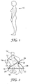
- FIG. 1 is a side view of a user 10 and FIG. 2 is a schematic illustration of the user's lower spine and pelvis.
- a load is carried by the user, such as on the shoulders, back, or hip, it is critical to carry the load in such a manner so as not to over stress the individual's back. This is especially important when loads of a repetitive nature, such as might be found in a workplace, are experienced.
- the user when postured in a relaxed upright stance, (shown in FIG. 1) as one might be standing on a factory floor, causes the spine 14 and the hip 18 to orient in a definable way, defining a sacral angle 20.
- the sacral angle 20 is the inclined angle that occurs between an imaginary plane 22 that horizontally transverses the hip 18 and a plane 24 aligned with the top of a sacrum 26, a lower portion of the spine 14.
- an optimum sacral angle 20 is one that minimizes stress on both the ligaments and the muscles of the lower back. From abiomechanical standpoint an optimum sacral angle 20 is generally considered to be about 30 degrees.
- a sacral angle 20 less than 30 degrees is caused when the pelvis 16 is rotated back (e.g., in direction of arrow 17); this orientation can place undue stress on the ligaments of the spine 14.
- a sacral angle 20 greater than 30 degrees occurs when the pelvis 16 is rotated forward (e.g., in direction of arrow 19), creating a posture that stresses the muscularity of the back.
- the belt To provide a comfortable and supportive fit, the belt must be held tightly against the wearer's body. Wearing a typical webbing belt with an attached respiratory component around a wearer's waist does not position the respiratory component firmly and rigidly against the wearer's body. Improper positioning of the load of the respiratory component on a wearer's back does not provide efficient distribution and transfer of loads to the user's skeletal frame, and the user discomfort and fatigue results. With the respiratory component load placed to the rear of the belt, the front of the belt tugs in a rearward direction on the front of the belt creating an uncomfortable and unnecessary force on the lower abdominal muscles.
- Belts formed from a strip of material are not easily adaptable to a variety of user body types, although the belt may be adaptable with regard to girth generally. Persons with exaggerated or minimal protrusions at the stomach or buttocks area require adjustable width and length of the belt to address the variances in their anatomy.
- the respiratory component In use, the respiratory component is generally exposed to hazardous environments, which causes contamination to the belt. While some materials and surfaces are readily decontaminatible, others such as stitched fabric or webbing are difficult to decontaminate. Existing fabric belts and straps are difficult to effectively clean because debris and toxins may become trapped in the fabric and/or stitching so as to resist removal and require costly cleaning procedures. Discarding contaminated equipment is costly and not desirable. Therefore, responders desire a belt that can be decontaminatible after each use, so that it can be reused.
- the belt should be relatively inexpensive and adaptable to a variety of wearers.
- the belt should facilitate easy decontamination of the respiratory protection system and an anatomically correct fit for a variety of user body types.
- the present invention is directed to a belt for use in carrying one or more waist-mounted respiratory protection components.
- the belt includes a main belt portion and a belt buckle portion.
- the main belt portion has a back section, a left side section, a right side section, a left connective section between the back section and the left side section, and a right connective section between the back section and the right side section.
- the back section is wider than both the left side section and the right side section and has a plurality of slots therein for use in mounting a respiratory protection component thereon.
- the left and right side and connective sections are symmetrically shaped relative to the back section and each side section has a generally horizontal forward segment and a downwardly angled rearward segment.
- the belt buckle portion includes a right piece connected to the right side section of the main belt portion and a left piece connected to the left side section of the main belt portion. At least one of the right and left pieces of the belt buckle portion is adjustable in length, and free ends of the right and left pieces are selectively connected together by a releasable buckle.
- the main belt portion is shaped to be secured around a user's pelvic girdle and to align the respiratory component thereon over the lumbar region of the user's spine, at an ideal angle of inclination of approximately 15 degrees, to distribute a weight of the respiratory component around a pelvis of the user, allow free leg movement, minimize pinching adj acent a user's iliac crests during such movement, and shift the rotational momentum of the weight of the respiratory component toward the user, thus further enhancing user comfort.
- the respiratory protection system includes a breathing face-piece 30, or head gear, and a respiratory component 32, such as a fan-forced positive pressure breathing device, commonly known as a Powered Air Purifying Respirator (PAPR), an air filter or monitor.
- a respiratory component 32 such as a fan-forced positive pressure breathing device, commonly known as a Powered Air Purifying Respirator (PAPR), an air filter or monitor.
- An air hose 34, or tube connects the respiratory component 32 to the breathing face-piece 30 to supply breathable air to a user 36.
- the respiratory component 32 is designed to be worn by a person working in an atmosphere with unwanted contaminants, including respiratory hazards.
- the PAPR 32 has a housing 32a and one or more filter units 32b, which serve to filter unwanted contaminants from the surrounding atmosphere, thus allowing a user wearing the PAPR to work in contaminated or hazardous areas.
- the PAPR 32 typically has a weight in the range of about 0.3 Kg to about 3.0 Kg.
- a PAPR is disclosed and described in U.S. Patent No. 6,575,165 , entitled “Apparatus and Method for Breathing Apparatus Component Coupling,” which has a weight of about 1.4 Kg.
- the present invention concerns an anatomically fitted, ergonomically designed belt 38 for carrying the respiratory component 32.
- the belt 38 may also be used with a variety of respiratory components for hands-free use in contaminated areas.
- the respiratory component 32 is attached to the anatomically fitted belt 38 for carrying by the user and positioned such that the load is carried at the rear of the belt 38.
- the respiratory component 32 attached to the belt 38 allows carriage by the user 36 leaving the hands free for other purposes.
- the belt 38 is configured to provide an anatomical fit wherein the hips carry the load of the respiratory component 32, leg movement is freed, and the lumbar of the back is firmly supported.
- the belt 38 also cushions the back of the user 36 while still maintaining rigidity to support the respiratory component 32.
- line 14 represents the curvature of a user's spine, including an upper cervical region 42, a kyphotic curve 44, lower lumbar region 12 and a lordotic curve 46.
- the respiratory component 32 and the belt 38 is formed from a decontaminatible material such that after use in hazardous areas, the belt 38 may be decontaminated for future reuse.
- the spine 14 can be considered as a modified elastic rod because of the flexibility of the spinal column, the shock-absorbing behavior of the discs and vertebrae, the stabilizing function of the longitudinal ligaments, and the elasticity of the ligamenta flava.
- the two curvatures of the spine in the sagittal plane, kyphotic 44 and lordotic 46, also contribute to the spring like capacity of the spine and allow the vertebral column to withstand higher loads than if it were straight.
- the extrinsic support provided by the trunk muscles helps stabilize and modify the loads on the spine 14 in both dynamic and static situations.
- the postural muscles When a persons stands, the postural muscles are constantly active. This activity is minimized when the body segments are well aligned.
- the line of gravity of the trunk usually passes ventral to the center of the fourth lumbar vertebral body. Thus, it falls ventral to the transverse axis of motion of the spine 14 and the motion segments are subjected to a forward-bending moment, which must be counterbalanced by ligament forces and erector spinea muscle forces. Any displacement of the line of gravity alters the magnitude and direction of the moment of the spine 14. For the body to return to equilibrium, the moment must be counteracted by increased muscle activity, which causes intermittent postural sway.
- the pelvis 16 also plays a role in the muscle activity and resulting loads on the spine 14 during standing.
- the base of the sacrum 26 is inclined forward and downward.
- the angle of the inclination, or sacral angle 20 is about 30 degrees to the transverse plane during relaxed standing. Tilting of the pelvis 16 about the transverse axis between the hip joints changes the angle.
- the sacral angle 20 decreases and the lumbar lordosis flattens. This flattening affects the thoracic spine, which extends slightly to adjust the center of gravity of the trunk so that energy expenditure, in terms of muscle work, is minimized.
- Body position affects the magnitude of the loads on the spine 14. These loads are minimal during well supported reclining and remain low during relaxed up-right standing.
- the present invention belt displaces the load of the respiratory component between the spine 14 and the pelvis 16 such that an optimum posture defined by the sacral angle 20 occurs.
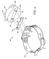
- FIG. 4 is an exploded perspective view of a waist-mounted respiratory component system 48.
- the waist-mounted respiratory component system 48 includes the belt 38, a mounting assembly 50 (discussed in detail below with respect to FIGS. 13-16 and 18-19) for mounting the respiratory component 32 to the belt 38, and the respiratory component 32.
- the belt 38 includes a plurality of spaced apart mounting slots 52, or clip openings, for attaching the mounting assembly 50 to the belt 38.
- the mounting assembly 50 is a clip that is woven through the slots 52 of the belt 38 such that first and second ends 54, 56 of the mounting assembly 50 are free for attaching to the respiratory component 32 and an intermediate portion 58 is connected to the belt 38 (as shown in FIGS. 14, 16 and 18).
- the belt 38 and the mounting assembly 50 are a unitary component.
- the belt 38 may include tabs, or projections, permanently attached thereto for mounting the respiratory component 32 thereon.
- U.S. Patent Application No. 10/749,177 entitled “Respiratory Component Mounting Assembly” (attorney docket number 59131US002) and filed on 30 December, 2003, discusses the mounting assembly 50 in further detail and is incorporated herein by reference.
- the respiratory component 32 includes at least two spaced apart openings 60, 62 for receiving the free ends 54, 56 of the mounting clip 50.
- the mounting slots 52 and clip openings 60, 62 shown in FIG. 4 are generally parallel and vertically aligned, those skilled in the art will recognize that other configurations and orientations for the slots and openings are possible.
- FIGS. 5-12 show an embodiment of the respiratory protection system belt 38.
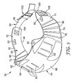
- FIG. 5 provides a perspective view of the belt 38
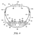
- FIGS. 6, 7, and 8 provide back (outer), side and top views, respectively.
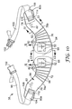
- FIGS. 9 and 10 are inner views of the belt 38
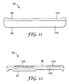
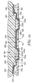
- FIGS. 11 and 12 are cross-sectional views of the belt 38 taken along lines 11 -- 11 and 12-12, respectively, of FIG. 10.
- the belt 38 for carrying one or more respiratory components 32 includes a main belt portion 64 and a belt buckle portion 66 connected to the main belt portion 64.
- the main belt portion 64 includes a back section 68, a left side section 70, a left connective section 72 between the back section 68 and the left side section 70, a right side section 74 and a right connective section 76 between the back section 68 and the right side section 74.
- the left and right side sections 70, 74 and the left and right connective sections 72, 76 are symmetrically shaped relative to the back section 68.
- Each side section 70, 74 has a generally horizontal forward segment 78a and 78b and, a downwardly angled rearward segment 80a and 80b (shown in FIG. 7).
- the back section 68 is wider than the other sections of the main belt portion 64 to provide support for the respiratory component 32 and distribute the load of the respiratory component to a user's hips.
- the back section 68 includes two sets of mounting slots, each comprised of three slots 52.
- the slots 52 are used for mounting the respiratory component 32 to the belt 38, and in particular, receive the mounting assembly 50.
- the main belt portion 64 may include connector elements 82 for use in mounting additional supportive or respiratory components to the belt 38.
- the main belt portion 64 includes an outer face 84 and an inner face 86.
- the inner face 86 has a generally vertically disposed recess 88 therein, which serves as an air flow channel.
- the recess 88 channels air along the belt 38, thereby making the belt 38 cooler to wear and reducing user perspiration.
- the inner face 86 at the connective sections 72, 76 includes generally vertically disposed channels 90 (FIG. 5). The channels 90 direct air away from a user's body, which gives breathability to the belt 38.
- the main belt portion 64 has a substantially conical shape such that the belt 38 secures around a user's pelvic girdle and aligns the respiratory component 32 thereon over the lumbar region 12 of a user's spine 14.
- the main belt portion 64 is aligned over the lumbar region at an angle of inclination 28 of about 15 degrees (i.e., -75 degrees from the hip plane 22 shown in FIG. 2).
- the belt 38 distributes the weight of the respiratory component 32 around a user's pelvis 16 such that a user's hips carry the load of the respiratory component 32.
- the shape and the position of the main belt portion 64 allows free leg movement of the user 36 and minimizes pinching adjacent a user's iliac crests during such movement.
- the position of the main belt portion 64 with respect to a user's spine 14 shifts the rotational momentum of the weight of the respirator component 32 to the user 36.
- the shape of the main belt portion 64 of the belt 38 facilitates positioning of the respiratory component 32, while the belt 38 is worn by a user, over a user's lumbar region 12 at an angle of inclination 28 to enhance comfort of a user.
- the main belt portion 64 has an upper peripheral edge 92 and a lower peripheral edge 94. As shown in FIGS. 5-8, the main belt portion 64 includes a flared portion at which the lower edge 94 extends outwardly, relative to a user, beyond the upper edge 92. Thereby, a diameter of the belt 3 8 along the upper peripheral edge 92 is less than a diameter of the belt 38 along the lower peripheral edge 94.
- the flared portion shown in the present embodiment extends along the entire main belt portion 64, including the left and right side sections 70, 74, in further embodiments of the belt 38 the flared portion is defined by the back section 68 only or a combination of the back section 68 and connective sections 72, 76.
- Each connective section 72, 76 of the main belt portion 64 includes hinges 96 that radiate downwardly and outwardly from the upper edge 92. The hinges 96 facilitate bending in use to accommodate movement of the user 36.
- the belt buckle portion 66 of the belt 38 includes a left piece 98 connected to the left side section 70 of the main belt portion 64 and a right piece 100 connected to the right side section 74 of the main belt portion 64.
- Each piece 98,100 of the belt buckle portion 66 is adjustable in length, although in further embodiments of the belt only one piece may be adjustable. Free ends of the left and right pieces 98,100 are selectively connected together by a buckle 102, such as a releasable buckle, or any other buckle known in the art.
- first ends 104,106 of the left and right pieces 98,100 of the belt buckle portion 66 connect to the respective left and right side sections 70, 74, for example, by stitching or adhesive.
- the left and right pieces 98,100 are releasably connected to the side sections 70, 74 to accommodate separation of the belt buckle portion 66 from the main belt portion 64.
- a releasable belt buckle portion 66 is desired when the left and right pieces 98, 100 are not comprised of a decontaminatible material.
- the left and right pieces 98, 100 are detachable for disposal and the main belt portion 64 may be decontaminated for reuse.
- Each side section 98,100 includes an opening 108 and 110 for receiving the first end 104, 106 of the respective belt piece 98,100 and the first end 104,106 of each belt piece 98,100 includes a hinged connective member 112 and 114.
- the connective member 112, 114 folds at its hinge to narrow the connective member 112, 114 to facilitate sliding of the connective member 112, 114 through the opening 108, 110 of the side section 70, 74.
- the connective member 112,114 is unfolded at the hinge such that the connective member 112, 114 is wider than the opening 108, 110 to prevent removal of the belt piece 98, 100 from the main belt portion 64.
- other suitable connection mechanisms are possible, such as snap-fit, interlocking members, or the like.
- the main belt portion 64 is formed as a laminate having an outer layer 116 and an inner layer 118.
- the outer layer 116 provides rigidity and the inner layer 118, which contacts a user's body, provides a cushioning layer.
- the main belt portion 64, and in particular the outer layer 116, is formed from a generally rigid material relative to the left and right pieces 98, 100 of the belt buckle portion 66.
- the main belt portion 64 is generally more rigid than the belt buckle portion 66, which facilitates support of the respiratory component 32 and distributes the weight of the respiratory component 32 across the main belt portion 64.
- the slots 52 in the back section 68 of the main belt portion 64 are reinforced with a reinforcement member 120, such as a plate.
- the reinforcement member 120 stabilizes the respiratory component 32 and prevents separation of the respiratory component 32 and the mounting assembly 50 or the belt 38, and movement of the respiratory component away from the belt 38.
- both the outer layer 116 and the inner layer 118 of the main belt portion 64 are formed from an ethyl vinyl acetate (EVA) copolymer with a polyolefin elastomer.
- EVA ethyl vinyl acetate
- One suitable EVA is made by Alveo (a Sekisui Company of Luzern, Switzerland).
- the outer layer 116 EVA has a density of about 125 kg/m 3 and the inner layer 118 EVA has a density of about 70 kg/m 3 to about 75 kg/m 3 .
- the outer layer 116 is more rigid than the inner layer 118 to provide rigidity and structure, whereas the inner layer 118 is less rigid and serves as a cushioning inner layer of the main belt portion 64 to provide more comfort to a user.
- the outer layer 116 has a thickness of about 3 mm (in non-embossed areas) and the inner layer 118 has a thickness of about 5 mm.
- EVA is a decontaminatible material and abrasion resistant, whereby if the main belt portion 64 is damaged (i.e., nicked), it will remain decontaminatible.
- the outer layer 116 is formed from a rigid, high density polyethylene (HDPE).
- the reinforcement members 120 of the slots 52 are formed from a low density polyethylene, such as an LDPE made by VTS Plastics (Liverpool, UK), having a thickness of about 1.5 mm.
- the belt 38 typically has a weight of about 240 grams.
- the main belt portion 64 is formed from a single, solid layer EVA or a foam surrounded by a polyurethane coated fabric. Whatever material is used to form the main belt portion should be a material that does not readily carry debris or contaminates, or bear a coating thereon having such contaminant resistant characteristics.
- sheets of EVA material for the outer and inner layers 116, 118 are flame laminated together. Each layer of material is heated until there is a thin layer of molten material on its surface. The two layers are than pressed together (e.g., embossing) and the materials weld together as each layer cools.
- the belt shape, slots, channels, hinges and other openings are formed in the main belt portion, for example, by stamping and/or embossing.
- optional reinforcement members are attached to the main belt portion by an EVA hot melt adhesive.
- the outer layer and inner layer are joined together with a suitable adhesive, such as an epoxy resin or a double-sided adhesive tape, or additional attachment means are used to attach the reinforcement members to the belt, such as stitching, welding or suitable fasteners.
- a suitable adhesive such as an epoxy resin or a double-sided adhesive tape
- additional attachment means are used to attach the reinforcement members to the belt, such as stitching, welding or suitable fasteners.
- the belt buckle portion 66 is formed from readily decontaminatible material.
- the belt pieces 98, 100 are formed from a polyester coated with polyurethane or PVC, which allows the belt buckle portion 66 to be wiped clean of contaminants.
- the thread areas may collect contaminates and are generally decontaminatible. Releasably connecting the belt buckle portion 66 to the main belt portion 64 permits the contaminated pieces to be removed, disposed and replaced with new, clean pieces, thereby maintaining the contaimination-free nature of the entire belt.
- FIG. 13 is a perspective view of mounting clip 50 for attaching the respiratory component 32 to the belt 38 and FIG. 14 is a cross-sectional view of the waist-mounted respiratory component system 48, taken along line A--A of FIG. 10, showing the respiratory component mounting clip 50 and the respiratory component 32 mounted to the inventive belt 38.
- the mounting clip 50 includes the intermediate portion 58, two spaced apart free ends 54, 56 connected to the intermediate portion 58, a first surface 122 and a second surface 124.
- the intermediate portion 58 extends between a first shoulder 126 and a second shoulder 128, while the first and second free ends 54, 56 extend from the first and second shoulders 126, 128, respectively.
- the free ends 54, 56 are aligned to extend in generally opposite directions.
- the first surface 122 of the intermediate portion 58 defines a channel 130 extending between a first outer wall 132 and a second outer wall 134.
- the channel 130 includes a stepped portion 136 extending towards the first surface 122 and defining a second channel 138 on the second surface 124 of the mounting clip 50.
- a depth of the first channel 130 (defined by walls 132 and 134) is greater than a depth of the second channel 138 (defined by walls 138a and 138b).
- the first and second free ends 54, 56 of the mounting clip 50 include first and second biased detent tabs 140, 142 extending generally downwardly and inwardly from the second surface 124 of the mounting clip 50.
- the mounting clip 50 is generally used to attach the respiratory component 32 to the belt 38.
- the intermediate portion 58 of the clip 50 is woven through the mounting slots 52b, 52c, 52d, and 52e of the belt 38, whereby the free ends 54, 56 project from the inner surface 86 of the belt 38.
- four of the mounting slots 52b, 52c, 52d, and 52e receive the intermediate portion 58 of the clip 50, and in particular walls 132, 138a, 138b, and 134, respectively.
- one of the two surfaces 122, 124 of the clip 50 aligns against either the outer face 84 or the inner face 86 of the belt 38.
- the respiratory component 32 includes first and second openings 60, 62 for removably receiving the free ends 54, 56 of the clip 50.
- the respiratory component 32 also includes first and second opposed detent surfaces 144, 146 adjacent the first and second clip openings 60, 62, respectively.
- the openings 60, 62 of the respiratory component 32 receive the free ends 54, 56 of the clip 50 whereby the detent tabs 140, 142 of the clip 50 form a locking engagement with the detent surfaces 144, 146 of the respiratory component 32.
- the mounting clip 50 firmly secures the respiratory component 32 to the belt 38 and prevents the respiratory component 32 from falling off the belt 38 during normal use, and provides strong enough attachment to prevent separation of the respiratory component 32 from the belt 38 even if caught on machinery or other apparatus.
- the mounting clip 50 provides easy attachment and detachment of the respiratory component 32 to and from the belt 3 8 and facilitates efficient interchange between respiratory components carried by the belt 38.
- the free ends 54, 56 of the clip 50 are inserted into or removed from the clip openings 60, 62 in the respiratory component 32.
- Detent tabs 140,142 are pressed towards the second surface 124 of the clip 50 to facilitate insertion and removal of the clip from the respiratory component.
- At least the free ends 54, 56 of the clip 50 are flexibly resilient to accommodate insertion and removal to and from the clip openings 60, 62 of the respiratory component 32.
- the intermediate portion 58 of the clip 50 is sufficiently flexible to weave through the mounting slots 52 of the belt 38.
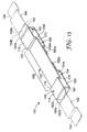
- FIG. 15 is a perspective view of a further embodiment of a mounting clip 150 for attaching the respiratory component 32 to the belt 38 and FIG. 16 is a cross-sectional view of the waist-mounted respiratory component system 48, taken along line A--A of FIG. 10, showing the respiratory component mounting clip 150 and the respiratory component 32 mounted to the inventive belt 38.
- the mounting clip 150 includes an intermediate portion 152, two spaced apart first and second free ends 154, 156 connected to the intermediate portion 152, a first surface 158 and a second surface 160.
- the intermediate portion 152 extends between a first pair of living hinges 162 and a second pair of living hinges 164, which connect the intermediate portion 152 to the first and second free ends 154, 156, respectively.
- the free ends 154, 156 of the mounting clip 150 fold and extend, at the living hinges 162, 164, between a folded, use position (shown in solid lines in FIG. 15) and an extended position (shown in broken lines in FIG. 15). In the use position, the free ends 154, 156 are aligned to extend toward each other and the second surface 130 of the intermediate portion 152 and the free ends 154, 156 are generally horizontally aligned.
- Each pair of living hinges 162, 164 includes an upper hinge 162a, 164a and a lower hinge 162b, 164b spaced apart and separated by a connector wall 166a, 166b.
- the first surface 158 of the intermediate portion 152 defines a channel 168 extending between a first channel wall 170 and a second channel wall 172.
- the intermediate portion 152 also includes first and second intermediate ledges 174,176.
- the first intermediate ledge 174 extends from a first shoulder 178 adjacent the first channel wall 170 to the first, upper living hinge 162a.
- the second intermediate ledge 176 extends from a second shoulder 180 adjacent the second channel wall 172 to the second, upper living hinge 162a.
- Each free end 154, 156 is stepped, as at stepped walls 154a and 156a, and includes an end ledge 182, 184 generally parallel and horizontally aligned with its respective intermediate ledge 174,176, when the free ends 154, 156 are in the extended position.
- Each free end 154 and 156 also includes an outermost free ledge 182a and 184a, respectively, extending beyond stepped walls 154a and 156a.
- the respiratory component 32 includes first and second clip openings 60, 62 for receiving the intermediate portion 152 of the clip 150.
- the openings 60, 62 of the respiratory component 32 receive the intermediate portion 152 of the clip 150 whereby the intermediate portion 152 is woven through the openings 60, 62 and passes along an outer wall 186 of the respiratory component 32.
- the free ends 154, 156 of the clip 150 are woven through the mounting slots 52a, 52c, 52d and 25e of the belt 38, whereby the end ledges 182 and 184 project from the outer surface 84 of the belt 38, while the outermost free ledges 182a and 184a project along the inner face 86 of the belt 38.
- An example of a suitable respiratory component for use with the mounting clip 150 is JUPITER brand turbo unit (Part No. 085-00-05P) from 3M United Kingdom PLC (Bracknell, UK).
- four of the mounting slots 52a, 52c, 52d, and 52f receive the walls 166a, 154a, 156a, and 168a, respectively, of free ends 154, 156 of the clip 150.
- one of the two faces (158, 160) of the clip 150 aligns against either the outer face 84 or the inner face 86 of the belt 38.
- the free ends 154, 156 of the clip 150 are inserted into or removed from the mounting slots 52 in the belt 38.
- At least the free ends 154, 156 of the clip 150 are flexibly resilient to accommodate insertion and removal to and from the mounting slots 52 of the belt 38.
- the intermediate portion 152 of the clip 150 is sufficiently flexible to weave through the clip openings 60, 62 of the respiratory component 32.
- the mounting assembly 150 shown in FIGS. 15 and 16 is particularly useful in explosive or dusty environments.
- a protective pouch 188 can be used to encase the respiratory component 32 to keep dust out of the component and/or prevent explosive materials from coming into contact with the component.
- FIG. 17 is a side view of the respiratory component 32 encased in the protective pouch 188.
- An example of a suitable protective pouch for use with the mounting clip 150 is JUPITER IS brand battery 4hr including pouch (Part No. 085-12-00P) from 3M United Kingdom PLC (Bracknell, UK).
- the respiratory component 32 is placed in the protective pouch 188 and the intermediate portion 152 of the mounting clip 150 is inserted through the openings 60, 62 on the respiratory component 32.
- the pouch 158 includes sleeves 190, 192 for free ends 154, 156 of the clip 150 to pass through.
- the free ends 154,156 of the mounting clip 150 project through the pouch 188 while the intermediate portion 152 is enclosed within the pouch 188. Because the free ends 154, 156 are received by the belt 38 (rather than the respiratory component 32), the respiratory component 32 is enclosed in the pouch 188, yet still detachable from the belt 3 8 without exposing the respiratory component 32 to a harmful environment.
- the respiratory component 32 is not encased in the protective pouch 188.
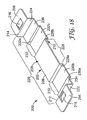
- FIG. 18 is a perspective view of further embodiment of a mounting clip 200 for attaching a respiratory component 201 to the belt 38 and FIG. 19 is a cross-sectional view of the waist-mounted respiratory component system 48, taken along line A--A of FIG. 10, showing the respiratory component mounting clip 200 and the respiratory component 201 mounted to the inventive belt 38.
- the mounting clip 200 includes an intermediate portion 202, two spaced apart free ends 204, 206 connected to the intermediate portion 202, a first surface 208 and a second surface 210.
- the intermediate portion 202 extends between a first shoulder 212 and a second shoulder 214, while the first and second free ends 204, 206 extend from the first and second shoulders 212, 214, respectively.
- the free ends 204, 206 are aligned to extend in generally opposite directions.
- the first and second free ends 204, 206 of the mounting clip 200 include first and second biased detent tabs 216, 218 extending generally downwardly and inwardly from the second surface 210 of the mounting clip 200.
- the first surface 208 of the intermediate portion 202 defines a channel 220 extending between a first outer wall 222 and a second outer wall 224.
- the channel 220 includes a stepped portion 226 extending towards the first surface 208 and defining a second channel 228 on the second surface 210 of the mounting clip 200.
- a depth of the first channel 220 (defined by walls 222 and 224) is greater than a depth of the second channel 228 (defined by walls 228a and 228b).
- Formed in the channel 220 are first and second subchannels 230, 232, which extend towards the second surface 210 and are defined on the first surface 208 of the mounting clip 200.
- a depth of each subchannel 230 (defined by walls 230a and 228a) and subchannel 232 (defined by walls 232a and 228b) is substantially equal to the depth of the second channel 228.
- First and second ledges 234, 236 extend between the first and second subchannels 230, 232 and the first and second outer walls 222, 224, respectively.
- Ledge 230b is in subchannel 230
- ledge 232b is in subchannel 232
- the stepped portion 226 is in channel 220 and separates subchannels 230 and 232.
- the intermediate portion 202 of the clip 200 is woven through the mounting slots 52 of the belt 38, whereby the free ends 204, 206 project from the inner surface 86 of the belt 38.
- four of the mounting slots 52b, 22c, 52d, and 52e receive walls 230a, 228a, 228b, and 232a, respectively, of the intermediate portion 202 of the clip 200.
- one of the ledges 234, 230b, 226, 232b, and 236 of the two faces (208, 210) of the clip 200 aligns against either the outer face 84 or the inner face 86 of the belt 38.
- the respiratory component 201 includes first and second openings 60, 62 for removably receiving the free ends 204, 206 of the clip 200.
- the respiratory component 201 also includes first and second opposed detent surfaces 238, 240 adjacent the first and second clip openings 60, 62, respectively.
- the openings 60, 62 of the respiratory component 201 receive the free ends 204, 206 of the clip 200 whereby the detent tabs 216, 218 of the clip 200 form a locking engagement with the detent surfaces 238, 240 of the respiratory component 201.
- the free ends 204, 206 of the clip 200 are inserted into or removed from the clip openings 60, 62 in the respiratory component 201.
- Detent tabs 216, 218 are pressed towards the second surface 210 of the clip 200 to facilitate insertion and removal to and from the clip openings 60, 62 of the respiratory component 201. At least the free ends 204, 206 of the clip 200 are flexibly resilient to accommodate insertion and removal to and from the clip openings 60, 62 of the respiratory component 201.
- the intermediate portion 202 of the clip 200 is sufficiently flexible to weave through the mounting slots 52 of the belt 38.
- An example of a suitable respiratory component for use with the mounting clip 200 is DUSTMASTER brand air filter unit (Part No. 021-00-38P) from 3M United Kingdom PLC (Bracknell, UK).
- the belt 38 includes sufficient mounting slots 52 (or other suitable fasteners or attachment elements) for accommodating more than one mounting assembly 50, and thereby facilitating the attachment of more than one respiratory component to the belt 38.
- additional components may attached anywhere along the outer perimeter of the belt 38.
- the alignment of the mounting slots 52 of the belt 38 may be other than generally parallel to accommodate differing orientations of mounting clips and connector receptacles on the respiratory components, as well as respiratory components of varying size.
Landscapes
- Health & Medical Sciences (AREA)
- Pulmonology (AREA)
- General Health & Medical Sciences (AREA)
- Business, Economics & Management (AREA)
- Emergency Management (AREA)
- Orthopedics, Nursing, And Contraception (AREA)
- Thermistors And Varistors (AREA)
- Resistance Heating (AREA)
- Corsets Or Brassieres (AREA)
- Respiratory Apparatuses And Protective Means (AREA)
- Finger-Pressure Massage (AREA)
Claims (9)
- Ceinture (38) destinée à être utilisée pour porter une ou plusieurs composantes (32) de protection respiratoire montées à la taille, caractérisée en ce qu'elle comporte :une portion (64) de ceinture principale possédant une section (68) arrière contenant une pluralité de fentes (52) à travers celle-ci, une section (70) latérale gauche, une section (72) connective gauche entre la section (68) arrière et la section (70) latérale gauche, une section (74) latérale droite, et une section (76) connective droite entre la section (68) arrière et la section (74) latérale droite dans laquelle la section (68) arrière est plus large à la fois que la section (70) latérale gauche et que la section (74) latérale droite ;
dans laquelle la portion (64) de ceinture principale a une forme en général frustoconique pour pouvoir être fixée autour de la ceinture pelvienne d'un utilisateur afin d'y aligner une composante de protection respiratoire au niveau de la région (12) lombaire de la colonne vertébrale (14) d'un utilisateur de sorte que le poids de la composante (32) respiratoire est distribué autour du pelvis de l'utilisateur ;une bride de montage (50) engagée dans la portion (64) de ceinture principale pour monter la composante (32) respiratoire sur la portion (64) de ceinture principale ; etune portion de boucle (66) de ceinture possédant une pièce droite reliée à la section latérale droite de la portion (64) de ceinture principale et une pièce gauche reliée à la section latérale gauche de la portion de ceinture principale. - Ceinture selon la revendication 1 dans laquelle les sections latérales et connectives gauche et droite ont une forme symétrique par rapport à la section arrière, et en outre dans laquelle chaque section latérale possède un segment vers l'avant en général horizontal et un segment vers l'arrière à un certain angle vers le bas.
- Ceinture selon la revendication 1 dans laquelle chaque section connective de la portion de ceinture principale définit une pluralité d'articulations rayonnant radialement vers le bas et vers l'extérieur pour faciliter la flexion lors de son utilisation.
- Ceinture selon la revendication 1 dans laquelle la portion de ceinture principale est munie d'une couche externe et d'une couche interne, la couche externe fournissant une rigidité et la couche interne fournissant une couche d'amortissement.
- Ceinture selon la revendication 1 dans laquelle la portion de ceinture principale est réalisée à partir de matériaux qui peuvent être facilement décontaminés.
- Ceinture selon la revendication 1 dans laquelle au moins une portion de la section arrière de la portion de ceinture principale est renforcée.
- Ceinture selon la revendication 1 dans laquelle la portion de ceinture principale a une face interne et une face externe, et dans laquelle la face interne sur la section arrière a au moins un canal de circulation d'air disposé en général verticalement à l'intérieur de celle-ci.
- Ceinture selon la revendication 1 dans laquelle la forme de la portion de ceinture principale maintient l'angle sacré formé par le pelvis et la colonne vertébrale de l'utilisateur à environ 30 degrés.
- Ceinture selon la revendication 1 dans laquelle la portion de ceinture principale a une forme lui permettant d'être fixée autour de la ceinture pelvienne de l'utilisateur et d'y aligner la composante respiratoire au niveau de la région lombaire de la colonne vertébrale de l'utilisateur à un angle d'inclinaison idéal d'environ 15°.
Priority Applications (1)
| Application Number | Priority Date | Filing Date | Title |
|---|---|---|---|
| PL04813637T PL1699531T3 (pl) | 2003-12-30 | 2004-12-09 | Anatomicznie dopasowany pas do zespołu respiracyjnego |
Applications Claiming Priority (2)
| Application Number | Priority Date | Filing Date | Title |
|---|---|---|---|
| US10/748,907 US7454800B2 (en) | 2003-12-30 | 2003-12-30 | Anatomically fitted respiratory component belt |
| PCT/US2004/041335 WO2005065780A1 (fr) | 2003-12-30 | 2004-12-09 | Ceinture a composante respiratoire et de forme anatomique |
Publications (2)
| Publication Number | Publication Date |
|---|---|
| EP1699531A1 EP1699531A1 (fr) | 2006-09-13 |
| EP1699531B1 true EP1699531B1 (fr) | 2007-08-08 |
Family
ID=34710998
Family Applications (1)
| Application Number | Title | Priority Date | Filing Date |
|---|---|---|---|
| EP04813637A Expired - Lifetime EP1699531B1 (fr) | 2003-12-30 | 2004-12-09 | Ceinture a composante respiratoire et de forme anatomique |
Country Status (12)
| Country | Link |
|---|---|
| US (1) | US7454800B2 (fr) |
| EP (1) | EP1699531B1 (fr) |
| KR (1) | KR20060113977A (fr) |
| CN (1) | CN1901972A (fr) |
| AT (1) | ATE369191T1 (fr) |
| AU (1) | AU2004311964B2 (fr) |
| BR (1) | BRPI0418217A (fr) |
| DE (1) | DE602004008112T2 (fr) |
| ES (1) | ES2288704T3 (fr) |
| PL (1) | PL1699531T3 (fr) |
| RU (1) | RU2006123337A (fr) |
| WO (1) | WO2005065780A1 (fr) |
Families Citing this family (22)
| Publication number | Priority date | Publication date | Assignee | Title |
|---|---|---|---|---|
| US7900278B2 (en) * | 2006-10-09 | 2011-03-08 | Safariland, Llc | Ergonomic duty gear belt |
| WO2009137770A2 (fr) * | 2008-05-09 | 2009-11-12 | Avon Protection Systems, Inc. | Appareil filtrant à ventilation assistée à répartition d’air et de ceinture intégrée |
| US9492105B1 (en) * | 2009-02-13 | 2016-11-15 | Cleveland Medical Devices Inc. | Device for sleep diagnosis |
| EP2555849B1 (fr) * | 2010-04-06 | 2018-06-27 | 3M Innovative Properties Company | Dispositif de filtration d'air |
| US20120055894A1 (en) * | 2010-09-06 | 2012-03-08 | Rooster Products International, Inc. | Belt merchandising system and method |
| GB2490743B (en) * | 2011-05-13 | 2017-03-22 | Berghaus Ltd | Load transfer belt |
| US10406387B2 (en) | 2012-02-15 | 2019-09-10 | 3M Innovative Properties Company | Interlock system for a respirator waist belt |
| US9119975B2 (en) | 2012-02-15 | 2015-09-01 | 3M Innovative Properties Company | Respirator waist belt |
| US20130261577A1 (en) * | 2012-04-02 | 2013-10-03 | Andre Gene Brazeau | Ostomy belt |
| WO2015066793A1 (fr) * | 2013-11-05 | 2015-05-14 | B-Ternia Inc. | Ceinture de taille pour applications de port de charge |
| CN103721353B (zh) * | 2014-01-23 | 2016-07-06 | 何正华 | 一种烟尘及重空气污染场合用呼吸器 |
| US9999546B2 (en) | 2014-06-16 | 2018-06-19 | Illinois Tool Works Inc. | Protective headwear with airflow |
| CN105617557A (zh) * | 2014-10-30 | 2016-06-01 | 哈尔滨聚吉轩科技开发有限公司 | 一种便携式雾霾净化装置 |
| CN104888378A (zh) * | 2015-05-26 | 2015-09-09 | 张萍 | 一种便携式灰尘净化装置 |
| US10499723B2 (en) | 2015-09-15 | 2019-12-10 | Santc Group, Inc. | Wearable modular carrying system and methods of use |
| US11812816B2 (en) | 2017-05-11 | 2023-11-14 | Illinois Tool Works Inc. | Protective headwear with airflow |
| USD881380S1 (en) | 2017-10-16 | 2020-04-14 | Gentex Corporation | Respirator |
| EP3697504B1 (fr) * | 2017-10-18 | 2022-06-29 | 3M Innovative Properties Company | Ensemble de support articulé pour appareil respiratoire autonome |
| RU2694539C1 (ru) * | 2018-04-24 | 2019-07-16 | Дмитрий Николаевич Пазухин | Держатель самоспасателя |
| US20210316176A1 (en) * | 2020-04-12 | 2021-10-14 | Alexander Andrew, Inc. Dba Falltech | Web harness waist pad belts |
| WO2022056253A1 (fr) * | 2020-09-11 | 2022-03-17 | Msa Technology, Llc | Appareil respiratoire à double mode |
| GB2623807B (en) | 2022-10-28 | 2024-10-23 | Jsp Ltd | Powered air purifying respirator |
Family Cites Families (24)
| Publication number | Priority date | Publication date | Assignee | Title |
|---|---|---|---|---|
| CA1119975A (fr) | 1977-05-31 | 1982-03-16 | John W. Tidland | Masques respiratoires portables filtreurs d'air |
| US4608716A (en) * | 1982-08-20 | 1986-09-02 | Michael Brumfield | Safety jump suit uniform and lifting mechanism for miners and other workers |
| US4756306A (en) * | 1984-03-20 | 1988-07-12 | Safeguard Technologies, Inc. | Therapeutic belt |
| US5105806A (en) * | 1988-11-23 | 1992-04-21 | Wbss | Rigid abdominal pad for lumbar/sacral support |
| US5009225A (en) * | 1989-11-30 | 1991-04-23 | Boehringer Mannheim Corporation | Personal ventilating system |
| US5052603A (en) | 1990-04-18 | 1991-10-01 | Cousins Haulkholder Incorporated | Implement holder |
| US5394870A (en) * | 1993-09-03 | 1995-03-07 | Minnesota Mining And Manufacturing Company | Respirator blower unit housing with pommel-like strap support member comprising lower exterior support surface |
| AU7416494A (en) | 1993-09-30 | 1995-04-13 | Christopher Terence Hession | A belt |
| US5564124A (en) * | 1995-04-20 | 1996-10-15 | Bio-Medical Devices, Inc | Personal body ventilation system |
| US5609283A (en) * | 1995-06-07 | 1997-03-11 | Dunlap & Codding, P.C. | Utility belt for painters and methods |
| US5728055A (en) * | 1996-01-30 | 1998-03-17 | Fisher Scientific Company | Therapeutic lumbosacral appliance |
| US5871132A (en) | 1996-04-22 | 1999-02-16 | Hargreaves; Annette H. | 3 in 1 fanniflap pack |
| US5944242A (en) | 1996-05-16 | 1999-08-31 | Musarella; Michael | Tool holder |
| US5943772A (en) * | 1997-08-19 | 1999-08-31 | Brazeway, Inc. | Method of cladding tubing and manufacturing condensor cores |
| US5833095A (en) | 1997-12-05 | 1998-11-10 | Task Corporation | Tool and fastener holder with detachable holding belt |
| US6394088B1 (en) * | 1998-11-06 | 2002-05-28 | Mark R. Frye | Oxygen-delivery system with portable oxygen meter |
| US6038747A (en) | 1999-02-03 | 2000-03-21 | Illinois Tool Works Inc. | Pack waist-belt and buckles therefor |
| US6206257B1 (en) | 1999-10-22 | 2001-03-27 | Ericsson Inc. | Swivel belt clip with bi-directional action |
| US6193122B1 (en) | 2000-01-03 | 2001-02-27 | Gregory R. Buckley | Rigid frame tool belt assembly |
| US6213365B1 (en) * | 2000-02-23 | 2001-04-10 | David Stocke | Painter's utility belt |
| GB0014713D0 (en) * | 2000-06-16 | 2000-08-09 | 3M Innovative Properties Co | Pressure regulator for a respirator system |
| US6575165B1 (en) | 2000-08-03 | 2003-06-10 | 3M Innovative Properties Company | Apparatus and method for breathing apparatus component coupling |
| ITMI20010097A1 (it) | 2001-01-19 | 2002-07-19 | Luca Florindo De | Depuratore d'aria portatile individuale |
| US6533740B2 (en) * | 2001-03-01 | 2003-03-18 | Amei Technologies Inc. | Lifting mechanism for a traction device |
-
2003
- 2003-12-30 US US10/748,907 patent/US7454800B2/en not_active Expired - Fee Related
-
2004
- 2004-12-09 RU RU2006123337/12A patent/RU2006123337A/ru not_active Application Discontinuation
- 2004-12-09 AU AU2004311964A patent/AU2004311964B2/en not_active Ceased
- 2004-12-09 KR KR1020067012994A patent/KR20060113977A/ko not_active Application Discontinuation
- 2004-12-09 WO PCT/US2004/041335 patent/WO2005065780A1/fr active IP Right Grant
- 2004-12-09 EP EP04813637A patent/EP1699531B1/fr not_active Expired - Lifetime
- 2004-12-09 AT AT04813637T patent/ATE369191T1/de not_active IP Right Cessation
- 2004-12-09 BR BRPI0418217-0A patent/BRPI0418217A/pt not_active Application Discontinuation
- 2004-12-09 CN CNA2004800393946A patent/CN1901972A/zh active Pending
- 2004-12-09 ES ES04813637T patent/ES2288704T3/es not_active Expired - Lifetime
- 2004-12-09 PL PL04813637T patent/PL1699531T3/pl unknown
- 2004-12-09 DE DE602004008112T patent/DE602004008112T2/de not_active Expired - Lifetime
Also Published As
| Publication number | Publication date |
|---|---|
| AU2004311964A1 (en) | 2005-07-21 |
| ATE369191T1 (de) | 2007-08-15 |
| PL1699531T3 (pl) | 2007-12-31 |
| DE602004008112D1 (de) | 2007-09-20 |
| KR20060113977A (ko) | 2006-11-03 |
| CN1901972A (zh) | 2007-01-24 |
| BRPI0418217A (pt) | 2007-04-27 |
| EP1699531A1 (fr) | 2006-09-13 |
| ES2288704T3 (es) | 2008-01-16 |
| US7454800B2 (en) | 2008-11-25 |
| RU2006123337A (ru) | 2008-02-10 |
| AU2004311964B2 (en) | 2010-08-12 |
| WO2005065780A1 (fr) | 2005-07-21 |
| US20050144706A1 (en) | 2005-07-07 |
| DE602004008112T2 (de) | 2008-04-30 |
Similar Documents
| Publication | Publication Date | Title |
|---|---|---|
| EP1699531B1 (fr) | Ceinture a composante respiratoire et de forme anatomique | |
| US7819120B2 (en) | Respiratory component mounting assembly | |
| EP2814579B1 (fr) | Assemblage de composants respiratoires | |
| AU2013219881B2 (en) | Interlock system for a respirator waist belt | |
| US9486654B1 (en) | Reconfigurable, modular ergonomic sit harness or saddle | |
| EP1127588B1 (fr) | Système de protection du visage et des voies respiratoires | |
| US9221373B1 (en) | Biomechanical protective system | |
| WO2016015104A1 (fr) | Dispositif de support | |
| US20160270466A1 (en) | Waist belt for load bearing applications |
Legal Events
| Date | Code | Title | Description |
|---|---|---|---|
| PUAI | Public reference made under article 153(3) epc to a published international application that has entered the european phase |
Free format text: ORIGINAL CODE: 0009012 |
|
| 17P | Request for examination filed |
Effective date: 20060602 |
|
| AK | Designated contracting states |
Kind code of ref document: A1 Designated state(s): AT BE BG CH CY CZ DE DK EE ES FI FR GB GR HU IE IS IT LI LT LU MC NL PL PT RO SE SI SK TR |
|
| GRAP | Despatch of communication of intention to grant a patent |
Free format text: ORIGINAL CODE: EPIDOSNIGR1 |
|
| RIN1 | Information on inventor provided before grant (corrected) |
Inventor name: HENDERSON, CHRISTOPHER P. Inventor name: TAYLOR, DAVID S. Inventor name: LEE, PETER D. |
|
| DAX | Request for extension of the european patent (deleted) | ||
| GRAS | Grant fee paid |
Free format text: ORIGINAL CODE: EPIDOSNIGR3 |
|
| GRAA | (expected) grant |
Free format text: ORIGINAL CODE: 0009210 |
|
| AK | Designated contracting states |
Kind code of ref document: B1 Designated state(s): AT BE BG CH CY CZ DE DK EE ES FI FR GB GR HU IE IS IT LI LT LU MC NL PL PT RO SE SI SK TR |
|
| REG | Reference to a national code |
Ref country code: GB Ref legal event code: FG4D |
|
| REG | Reference to a national code |
Ref country code: CH Ref legal event code: EP |
|
| REG | Reference to a national code |
Ref country code: IE Ref legal event code: FG4D |
|
| REF | Corresponds to: |
Ref document number: 602004008112 Country of ref document: DE Date of ref document: 20070920 Kind code of ref document: P |
|
| REG | Reference to a national code |
Ref country code: SE Ref legal event code: TRGR |
|
| ET | Fr: translation filed | ||
| REG | Reference to a national code |
Ref country code: PL Ref legal event code: T3 |
|
| REG | Reference to a national code |
Ref country code: ES Ref legal event code: FG2A Ref document number: 2288704 Country of ref document: ES Kind code of ref document: T3 |
|
| PG25 | Lapsed in a contracting state [announced via postgrant information from national office to epo] |
Ref country code: NL Free format text: LAPSE BECAUSE OF FAILURE TO SUBMIT A TRANSLATION OF THE DESCRIPTION OR TO PAY THE FEE WITHIN THE PRESCRIBED TIME-LIMIT Effective date: 20070808 Ref country code: BG Free format text: LAPSE BECAUSE OF FAILURE TO SUBMIT A TRANSLATION OF THE DESCRIPTION OR TO PAY THE FEE WITHIN THE PRESCRIBED TIME-LIMIT Effective date: 20071108 Ref country code: IS Free format text: LAPSE BECAUSE OF FAILURE TO SUBMIT A TRANSLATION OF THE DESCRIPTION OR TO PAY THE FEE WITHIN THE PRESCRIBED TIME-LIMIT Effective date: 20071208 Ref country code: LT Free format text: LAPSE BECAUSE OF FAILURE TO SUBMIT A TRANSLATION OF THE DESCRIPTION OR TO PAY THE FEE WITHIN THE PRESCRIBED TIME-LIMIT Effective date: 20070808 |
|
| PGFP | Annual fee paid to national office [announced via postgrant information from national office to epo] |
Ref country code: ES Payment date: 20071226 Year of fee payment: 4 |
|
| NLV1 | Nl: lapsed or annulled due to failure to fulfill the requirements of art. 29p and 29m of the patents act | ||
| REG | Reference to a national code |
Ref country code: CH Ref legal event code: PL |
|
| PG25 | Lapsed in a contracting state [announced via postgrant information from national office to epo] |
Ref country code: AT Free format text: LAPSE BECAUSE OF FAILURE TO SUBMIT A TRANSLATION OF THE DESCRIPTION OR TO PAY THE FEE WITHIN THE PRESCRIBED TIME-LIMIT Effective date: 20070808 Ref country code: LI Free format text: LAPSE BECAUSE OF FAILURE TO SUBMIT A TRANSLATION OF THE DESCRIPTION OR TO PAY THE FEE WITHIN THE PRESCRIBED TIME-LIMIT Effective date: 20070808 Ref country code: CH Free format text: LAPSE BECAUSE OF FAILURE TO SUBMIT A TRANSLATION OF THE DESCRIPTION OR TO PAY THE FEE WITHIN THE PRESCRIBED TIME-LIMIT Effective date: 20070808 |
|
| PGFP | Annual fee paid to national office [announced via postgrant information from national office to epo] |
Ref country code: PL Payment date: 20071203 Year of fee payment: 4 |
|
| PG25 | Lapsed in a contracting state [announced via postgrant information from national office to epo] |
Ref country code: BE Free format text: LAPSE BECAUSE OF FAILURE TO SUBMIT A TRANSLATION OF THE DESCRIPTION OR TO PAY THE FEE WITHIN THE PRESCRIBED TIME-LIMIT Effective date: 20070808 |
|
| PG25 | Lapsed in a contracting state [announced via postgrant information from national office to epo] |
Ref country code: DK Free format text: LAPSE BECAUSE OF FAILURE TO SUBMIT A TRANSLATION OF THE DESCRIPTION OR TO PAY THE FEE WITHIN THE PRESCRIBED TIME-LIMIT Effective date: 20070808 Ref country code: GR Free format text: LAPSE BECAUSE OF FAILURE TO SUBMIT A TRANSLATION OF THE DESCRIPTION OR TO PAY THE FEE WITHIN THE PRESCRIBED TIME-LIMIT Effective date: 20071109 |
|
| PG25 | Lapsed in a contracting state [announced via postgrant information from national office to epo] |
Ref country code: SK Free format text: LAPSE BECAUSE OF FAILURE TO SUBMIT A TRANSLATION OF THE DESCRIPTION OR TO PAY THE FEE WITHIN THE PRESCRIBED TIME-LIMIT Effective date: 20070808 Ref country code: PT Free format text: LAPSE BECAUSE OF FAILURE TO SUBMIT A TRANSLATION OF THE DESCRIPTION OR TO PAY THE FEE WITHIN THE PRESCRIBED TIME-LIMIT Effective date: 20080108 Ref country code: CZ Free format text: LAPSE BECAUSE OF FAILURE TO SUBMIT A TRANSLATION OF THE DESCRIPTION OR TO PAY THE FEE WITHIN THE PRESCRIBED TIME-LIMIT Effective date: 20070808 |
|
| PLBE | No opposition filed within time limit |
Free format text: ORIGINAL CODE: 0009261 |
|
| STAA | Information on the status of an ep patent application or granted ep patent |
Free format text: STATUS: NO OPPOSITION FILED WITHIN TIME LIMIT |
|
| PG25 | Lapsed in a contracting state [announced via postgrant information from national office to epo] |
Ref country code: RO Free format text: LAPSE BECAUSE OF FAILURE TO SUBMIT A TRANSLATION OF THE DESCRIPTION OR TO PAY THE FEE WITHIN THE PRESCRIBED TIME-LIMIT Effective date: 20070808 |
|
| 26N | No opposition filed |
Effective date: 20080509 |
|
| PG25 | Lapsed in a contracting state [announced via postgrant information from national office to epo] |
Ref country code: MC Free format text: LAPSE BECAUSE OF NON-PAYMENT OF DUE FEES Effective date: 20071231 |
|
| PG25 | Lapsed in a contracting state [announced via postgrant information from national office to epo] |
Ref country code: IE Free format text: LAPSE BECAUSE OF NON-PAYMENT OF DUE FEES Effective date: 20071210 |
|
| PG25 | Lapsed in a contracting state [announced via postgrant information from national office to epo] |
Ref country code: EE Free format text: LAPSE BECAUSE OF FAILURE TO SUBMIT A TRANSLATION OF THE DESCRIPTION OR TO PAY THE FEE WITHIN THE PRESCRIBED TIME-LIMIT Effective date: 20070808 |
|
| PGFP | Annual fee paid to national office [announced via postgrant information from national office to epo] |
Ref country code: FI Payment date: 20081230 Year of fee payment: 5 |
|
| PG25 | Lapsed in a contracting state [announced via postgrant information from national office to epo] |
Ref country code: SI Free format text: LAPSE BECAUSE OF FAILURE TO SUBMIT A TRANSLATION OF THE DESCRIPTION OR TO PAY THE FEE WITHIN THE PRESCRIBED TIME-LIMIT Effective date: 20070808 |
|
| PG25 | Lapsed in a contracting state [announced via postgrant information from national office to epo] |
Ref country code: CY Free format text: LAPSE BECAUSE OF FAILURE TO SUBMIT A TRANSLATION OF THE DESCRIPTION OR TO PAY THE FEE WITHIN THE PRESCRIBED TIME-LIMIT Effective date: 20070808 |
|
| PG25 | Lapsed in a contracting state [announced via postgrant information from national office to epo] |
Ref country code: LU Free format text: LAPSE BECAUSE OF NON-PAYMENT OF DUE FEES Effective date: 20071209 |
|
| PGFP | Annual fee paid to national office [announced via postgrant information from national office to epo] |
Ref country code: SE Payment date: 20081229 Year of fee payment: 5 |
|
| PG25 | Lapsed in a contracting state [announced via postgrant information from national office to epo] |
Ref country code: HU Free format text: LAPSE BECAUSE OF FAILURE TO SUBMIT A TRANSLATION OF THE DESCRIPTION OR TO PAY THE FEE WITHIN THE PRESCRIBED TIME-LIMIT Effective date: 20080209 Ref country code: TR Free format text: LAPSE BECAUSE OF FAILURE TO SUBMIT A TRANSLATION OF THE DESCRIPTION OR TO PAY THE FEE WITHIN THE PRESCRIBED TIME-LIMIT Effective date: 20070808 |
|
| PGFP | Annual fee paid to national office [announced via postgrant information from national office to epo] |
Ref country code: FR Payment date: 20081217 Year of fee payment: 5 |
|
| PG25 | Lapsed in a contracting state [announced via postgrant information from national office to epo] |
Ref country code: PL Free format text: LAPSE BECAUSE OF NON-PAYMENT OF DUE FEES Effective date: 20081209 |
|
| REG | Reference to a national code |
Ref country code: ES Ref legal event code: FD2A Effective date: 20081210 |
|
| REG | Reference to a national code |
Ref country code: PL Ref legal event code: LAPE |
|
| PG25 | Lapsed in a contracting state [announced via postgrant information from national office to epo] |
Ref country code: ES Free format text: LAPSE BECAUSE OF NON-PAYMENT OF DUE FEES Effective date: 20081210 |
|
| EUG | Se: european patent has lapsed | ||
| PG25 | Lapsed in a contracting state [announced via postgrant information from national office to epo] |
Ref country code: FI Free format text: LAPSE BECAUSE OF NON-PAYMENT OF DUE FEES Effective date: 20091209 |
|
| REG | Reference to a national code |
Ref country code: FR Ref legal event code: ST Effective date: 20100831 |
|
| PG25 | Lapsed in a contracting state [announced via postgrant information from national office to epo] |
Ref country code: FR Free format text: LAPSE BECAUSE OF NON-PAYMENT OF DUE FEES Effective date: 20091231 |
|
| PG25 | Lapsed in a contracting state [announced via postgrant information from national office to epo] |
Ref country code: SE Free format text: LAPSE BECAUSE OF NON-PAYMENT OF DUE FEES Effective date: 20091210 |
|
| PGFP | Annual fee paid to national office [announced via postgrant information from national office to epo] |
Ref country code: IT Payment date: 20071231 Year of fee payment: 4 |
|
| PGFP | Annual fee paid to national office [announced via postgrant information from national office to epo] |
Ref country code: GB Payment date: 20181205 Year of fee payment: 15 |
|
| PGFP | Annual fee paid to national office [announced via postgrant information from national office to epo] |
Ref country code: DE Payment date: 20191126 Year of fee payment: 16 |
|
| GBPC | Gb: european patent ceased through non-payment of renewal fee |
Effective date: 20191209 |
|
| PG25 | Lapsed in a contracting state [announced via postgrant information from national office to epo] |
Ref country code: GB Free format text: LAPSE BECAUSE OF NON-PAYMENT OF DUE FEES Effective date: 20191209 |
|
| REG | Reference to a national code |
Ref country code: DE Ref legal event code: R119 Ref document number: 602004008112 Country of ref document: DE |
|
| PG25 | Lapsed in a contracting state [announced via postgrant information from national office to epo] |
Ref country code: DE Free format text: LAPSE BECAUSE OF NON-PAYMENT OF DUE FEES Effective date: 20210701 |