EP1699150B1 - Vorrichtung zur Regeneration von optischen Impulsen, System mit dieser Vorrichtung und Verwendung dieser Vorrichtung - Google Patents
Vorrichtung zur Regeneration von optischen Impulsen, System mit dieser Vorrichtung und Verwendung dieser Vorrichtung Download PDFInfo
- Publication number
- EP1699150B1 EP1699150B1 EP06290331A EP06290331A EP1699150B1 EP 1699150 B1 EP1699150 B1 EP 1699150B1 EP 06290331 A EP06290331 A EP 06290331A EP 06290331 A EP06290331 A EP 06290331A EP 1699150 B1 EP1699150 B1 EP 1699150B1
- Authority
- EP
- European Patent Office
- Prior art keywords
- optical
- filter
- pulses
- regeneration device
- frequency
- Prior art date
- Legal status (The legal status is an assumption and is not a legal conclusion. Google has not performed a legal analysis and makes no representation as to the accuracy of the status listed.)
- Expired - Lifetime
Links
Images
Classifications
-
- H—ELECTRICITY
- H04—ELECTRIC COMMUNICATION TECHNIQUE
- H04B—TRANSMISSION
- H04B10/00—Transmission systems employing electromagnetic waves other than radio-waves, e.g. infrared, visible or ultraviolet light, or employing corpuscular radiation, e.g. quantum communication
- H04B10/25—Arrangements specific to fibre transmission
- H04B10/2507—Arrangements specific to fibre transmission for the reduction or elimination of distortion or dispersion
- H04B10/25077—Arrangements specific to fibre transmission for the reduction or elimination of distortion or dispersion using soliton propagation
Definitions
- the present invention relates to an optical pulse regeneration device, an installation comprising such a device and a use of this device.
- the invention relates to the regeneration of dispersion-managed soliton pulses transmitted on an optical fiber.
- Soliton pulses managed in dispersion are also called solitons DM pulses (of the English “Dispersion-Managed solitons").
- DM soliton pulses have the property of propagating periodically without deformation in a non-linear medium, since these particular pulses are solution of the nonlinear Schrödinger equation.
- Collisions between solitons DM pulses belonging to different channels of the optical fiber are also a source of jitter (called collision)
- optical pulse regeneration device comprising an optical bandpass filter adapted for time synchronization and pulse intensity stabilization, in particular according to the document entitled " Linear Stability Analysis of Dispersion-Managed Solitons Controlled by Filters, by J. Kumasako and M. Matsumoto, from the Journal of Lightwave Technology, Volume 18, No. 8, August 2000 .
- the filter is adjusted by adjusting its center frequency and width.
- the use of a bandpass filter allows, on the one hand, a temporal synchronization of the pulses by refocusing them on the central frequency of the filter, and on the other hand, a stabilization of intensity of these pulses by filtering the frequencies extremes of the spectrum of pulses, which appeared during their propagation.
- the filter For the filter to be effective, it must be narrow enough to limit the spectral width of a pulse and to suppress noise. However, if the filter is too narrow, it may change the optimal shape of the pulse at the risk of destabilizing it and disrupt its propagation in the optical fiber. The choice of the spectral width of the filter therefore results from a compromise.
- the filter used can not be too narrow, the filter is ineffective in suppressing the amplified spontaneous emission noise. Therefore, the device of regeneration of the state of the art is inefficient to suppress this noise which therefore tends to accumulate during the transmission of pulses in the optical fiber. This is particularly true in a wavelength multiplexed line.
- the aim of the invention is to provide an optical pulse regeneration device which can be easily and precisely adjusted to ensure both temporal synchronization, intensity stabilization and noise suppression of transmitted pulses.
- the subject of the invention is an optical pulse regeneration device comprising an optical bandpass filter adapted for the time synchronization and intensity stabilization of soliton pulses managed in dispersion, characterized in that it further comprises noise suppression means, separate from the bandpass filter.
- the noise suppression means being distinct from the bandpass filter, the filter can be adjusted independently, to optimize its time synchronization and pulse intensity stabilization functions, and the noise suppression means.
- the noise suppression means comprise a saturable absorber, for the suppression of amplified spontaneous emission noise.
- a saturable absorber in combination with an optical filter makes it possible to obtain an entirely passive optical regeneration device.
- Such a regeneration device is particularly advantageous for transoceanic applications in which an electrical power supply must be limited to the strict minimum because of its difficulty of implementation.
- Nonlinear Optical Loop Miror non-linear optical loop mirror
- a highly non-linear fiber as amplified spontaneous emission noise suppression means since their transfer function is similar to that of the saturable absorber.
- the transfer function of the noise canceling means is a staircase transfer function.
- the transfer function of the filter has a substantially Gaussian or sinus profile.
- soliton pulses are substantially Gaussian profile pulses, their spectrum has a Gaussian profile. It is therefore advantageous for the transfer function of the filter to be as close as possible to the pulse spectrum so as not to destabilize them.
- Sine filters and Gaussian filters have very similar profiles. We can use either a Gaussian filter or a sine filter to regenerate solitons DM pulses.
- the frequency width at half height of the filter is substantially equal to twice the frequency width at mid-height of the soliton pulses managed in dispersion to be regenerated. This parameterization of the filter makes it possible to sufficiently filter the pulses without destabilizing their propagation.
- the bandpass filter is adapted to pass a plurality of distinct frequency bands predefined and separated two by two by a frequency band attenuated by the filter, so as to simultaneously filter a plurality of frequency-multiplexed pulses. in an optical signal.
- the filter is periodic in frequency.
- a periodic filter will be taken whose modulation depth is between 0.5 and 4 dB, preferably between 1 and 4 dB and / or whose modulation depth is between 10% and 60% of the frequency height of the pulses to be regenerated.
- This value of the modulation depth makes it possible to obtain satisfactory temporal re-synchronization of the pulses as well as suppression of the amplitude-effective noise without destabilizing the soliton DM pulses.
- a Fabry-Perot type filter is an example of a periodic frequency bandpass filter that can be used in the device of the invention.
- the subject of the invention is also an optical transmission facility for soliton pulses managed in dispersion, comprising means for propagating optical pulses, characterized in that it comprises an optical pulse regeneration device as previously defined, inserted in the propagation means.
- the regeneration device is inserted into the propagation means in the vicinity of a point where the spectral width of the pulses reaches a maximum.
- the optical pulse propagation means comprising first abnormal dispersion propagation means and second normal dispersion propagation means, the optical pulse propagation means are adapted so that the pulses reach a maximum of maximum spectral width in the vicinity of the middle of the first propagation means.
- the invention also relates to the use of a device according to the invention for the regeneration of soliton pulses managed in dispersion.
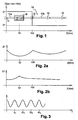
- the optical transmission system shown on the figure 1 comprises a line fiber 10 forming means for propagating an optical signal.
- the optical signal considered is composed of a plurality of frequency-multiplexed channels.
- the multiplexing frequencies are multiples of a frequency ⁇ 0 .
- Each channel is composed of DM solitons. These pulses are used for very high speed optical transmission applications, for example transmissions at 40 Gbit / s or higher.
- bit-time denotes the transmission period of the pulses.
- the half-time temporal width of soliton DM pulses is generally of the order of half the bit-time.
- the line fiber 10 comprises a first portion 10a fulfilling a function of propagation means with abnormal dispersion, whose dispersion coefficient D + is for example equal to 2.55 ps / nm / km.
- This first portion of fiber 10a with abnormal dispersion is extended by a second portion of fiber 10b with normal dispersion, of which the dispersion coefficient D - is equal to -2.45 ps / nm / km.
- the first and second fiber portions 10a and 10b each have a length of 100 km.
- the scheme of the figure 1 can be reproduced periodically to provide a line fiber 10 of much greater length, including a line fiber for transoceanic transmissions.
- the optical transmission installation also includes optical amplifiers 12 inserted at regular intervals in the line fiber 10. These amplifiers are at the origin of the amplified spontaneous emission noise disturbing the pulses. This noise results in the appearance of disturbing frequencies regularly distributed in the pulse spectrum.
- a soliton pulse DM generally comprises several components of different frequencies because of its time width.
- the refractive index of the optical fiber varies as a function of frequency, and the speed of propagation of a pulse on a fiber depends on the refractive index of the fiber. Consequently, the different components of the pulse are transmitted on the line fiber 10 at different speeds and the pulse width varies during its propagation in the line fiber 10. We speak of linear dispersive effects .
- the pulse In addition to the linear dispersive effects, the pulse also undergoes nonlinear effects such as self-phase modulation. These effects cause variations in the spectral width of the pulse.
- the pulses undergo deformation and need to be regenerated at regular intervals.
- An optical regeneration device 16 is inserted into the line fiber 10. It comprises a band-pass filter 18 and a saturable absorber 20.
- the band-pass filter is adapted for the time synchronization and the stabilization of the intensity of the current.
- solitons DM by removing the extreme frequencies of the spectrum to refocus the pulse on its initial frequency.
- the transfer function of the filter has a substantially Gaussian or sinus profile.
- the saturable absorber constitutes noise suppression means.
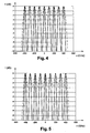
- the figure 2a is a graph representing the time width of a pulse as a function of its propagation in the line fiber 10. As a function of the dispersion coefficient of the line fiber 10, the time width of a pulse increases or decreases, which causes pulse beats. The time width of the pulse reaches local minimums in the middle of the first fiber portion 10a and in the middle of the second fiber portion 10b.
- the non-linear effects cause variations in the spectral width of the pulse as shown in FIG. figure 2b .
- the spectral width reaches a maximum substantially in the middle of the first fiber portion 10a.
- the optical regeneration device 16 is therefore preferably inserted in the vicinity of the middle of the first fiber portion 10a, where the spectral width reaches this maximum.
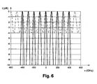
- the band-pass filter 18 is for example a Fabry-Perot periodic optical filter, the frequency profile of which is shown in FIG. figure 3 . It is constituted by the periodic repetition of a predefined pattern. Each pattern is intended to filter one of the channels of the signal transmitted on the line fiber 10. For this purpose, each pattern is centered on a frequency multiple of the channel multiplexing frequency ⁇ 0 .
- the filter adjustment is made by adjusting the profile of the periodic pattern, which acts on the depth of modulation of the filter.
- the modulation depth characterizes the selectivity of the filter.
- a high modulation depth means that the filter passes only very narrow frequency bands and strongly attenuates the intermediate frequency bands.
- a low modulation depth means that the filter passes wide frequency bands, and the intermediate frequencies are only slightly attenuated.
- the filter of the invention preferably has a moderate modulation depth. Indeed, the depth of modulation of the filter must not be too low in order to obtain the desired temporal synchronization and amplitude stabilization effects, nor too strong not to change the profile of the pulses too much, and to disturb their propagation.
- the half-height frequency width of one of the patterns of the periodic filter is set to be about twice the frequency halfway width of the signal at the point where the filter is located. More specifically, we will take a periodic filter whose modulation depth is between 0.5 and 4 dB and / or whose modulation depth is between 10% and 60% of the frequency height of the pulses to be regenerated.
- the periodic filter does not effectively suppress the interfering frequencies, interposed between the multiplexing frequencies, which are due to amplified spontaneous amplification noise.
- the saturable absorber 20 therefore has the role of suppressing this amplified spontaneous amplification noise by only passing through the signals whose amplitude is at least equal to a predetermined minimum threshold.
- the bit time is equal to 25 picoseconds (ps) and the cycle ratio is 50%, the half width of a pulse is 12.5 ps.
- the width T 0 to 1 / exp (1) of a pulse is then considered.
- To 7.5070 ps.
- the parameter of the Gaussian filter (denoted by P) is chosen such that the half-height width of a Gaussian filter pattern 18 is equal to twice the spectral width at mid-height of the Gaussian pulses constituting the channels.
- Dashed lines are shown respectively on the Figures 4 and 5 the intensity response of the periodic Gaussian filter 18 for values of P equal to To / 2.20 * 1e-3 and To / 2.00 * 1 e-3, which corresponds to respective modulation depths of 2dB and 3dB.
- P the intensity response of the periodic Gaussian filter 18 for values of P equal to To / 2.20 * 1e-3 and To / 2.00 * 1 e-3, which corresponds to respective modulation depths of 2dB and 3dB.
- P To obtain a modulation depth of 4 dB, we take a value of P equal to To / 1.86 * 1 e-3.
- the filter period is 100 GHz, the spectral spacing between the transmission channels.
- M is 0.365, 0.5 and 0.6.
- noise suppression means any optical device whose transfer function has substantially a step shape (like that of a saturable absorber) so as to eliminate all the signals whose maximum intensity is less than a threshold intensity and let pass the signals whose maximum intensity exceeds the threshold intensity.
- a nonlinear optical loop mirror may be used.
- an optical regeneration device as described above (that is to say combining a Gaussian or periodic sinus filter and a saturable absorber) allows the optical regeneration of DM soliton pulses in a fully passive manner and regenerating possibly simultaneously all the multiplexed channels of the same signal.
Landscapes
- Physics & Mathematics (AREA)
- Electromagnetism (AREA)
- Engineering & Computer Science (AREA)
- Computer Networks & Wireless Communication (AREA)
- Signal Processing (AREA)
- Optical Communication System (AREA)
- Optical Modulation, Optical Deflection, Nonlinear Optics, Optical Demodulation, Optical Logic Elements (AREA)
- Lasers (AREA)
- Gyroscopes (AREA)
Claims (13)
- Vorrichtung (16) zur optischen Regenerierung von Impulsen, die ein optisches Bandpassfilter (18) aufweist, das für die zeitliche Synchronisation und die Intensitätsstabilisierung von Dispersions-gemanagten Solitonen-Impulsen geeignet ist, wobei das Bandpassfilter (18) geeignet ist, mehrere unterschiedliche vordefinierte und paarweise von einem Bereich von durch das Filter gedämpften Frequenzen getrennte Frequenzbereiche durchzulassen, um gleichzeitig mehrere frequenzmultiplexierte Impulse in einem optischen Signal zu filtern, dadurch gekennzeichnet, dass sie außerdem Einrichtungen (20) zur Rauschunterdrückung aufweist, die sich von dem Bandpassfilter (18) unterscheiden, und dass das Bandpassfilter (18) eine geringe Modulationstiefe hat, die zwischen 10 % und 60 % der Frequenzhöhe der zu regenerierenden Impulse liegt.
- Optische Regenerierungsvorrichtung (16) nach Anspruch 1, bei der die Modulationstiefe des Filters (18) zwischen 0,5 und 4dB, vorzugsweise zwischen 1 und 4dB liegt.
- Optische Regenerierungsvorrichtung (16) nach einem der Ansprühe 1 bis 2, bei der die Rauschunterdrückungseinrichtungen (20) einen sättigbaren Absorber (20) zur Rauschunterdrückung einer verstärkten spontanen Emission aufweisen.
- Optische Regenerierungsvorrichtung (16) nach einem der Ansprüche 1 bis 2, bei der die Rauschunterdrückungseinrichtungen (20) einen nichtlinearen optischen Schleifenspiegel zur Rauschunterdrückung einer verstärkten spontanen Emission aufweisen.
- Optische Regenerierungsvorrichtung (16) nach einem der Ansprüche 1 bis 2, bei der die Rauschunterdrückungseinrichtungen (20) eine hoch nichtlineare Faser zur Rauschunterdrückung einer verstärkten spontanen Emission aufweisen.
- Optische Regenerierungsvorrichtung (16) nach einem der Ansprüche 1 bis 5, bei der die Transferfunktion des Filters (18) im Wesentlichen ein Gauß'sches oder ein Sinusprofil hat.
- Optische Regenerierungsvorrichtung (16) nach Anspruch 6, bei dem die Frequenzbreite auf halber Höhe des Filters (18) im Wesentlichen gleich dem Doppelten der Frequenzbreite auf halber Höhe der zu regenerierenden Impulse ist.
- Optische Regenerierungsvorrichtung (16) nach einem der Ansprüche 1 bis 7, bei der das Filter frequenzperiodisch ist.
- Optische Regenerierungsvorrichtung (16) nach Anspruch 8, bei der das Filter ein Filter vom Typ Fabry-Perot ist.
- Optische Übertragungsanlage von Dispersions-gemanagten Solitonen-Impulsen, die Einrichtungen (10) zur Ausbreitung von optischen Impulsen aufweist, dadurch gekennzeichnet, dass sie eine Vorrichtung (16) zur optischen Regenerierung der Impulse nach einem der Ansprüche 1 bis 9, eingefügt in die Ausbreitungseinrichtungen (10), aufweist.
- Optische Übertragungsanlage nach Anspruch 10, bei der die Regenerierungsvorrichtung (16) in die Ausbreitungseinrichtungen (10) in der Nähe eines Punkts eingefügt ist, an dem die Spektralbreite der Impulse ein Maximum erreicht.
- Optische Übertragungsanlage nach Anspruch 11, bei der die Einrichtungen (10) zur Ausbreitung optischer Impulse erste Einrichtungen (10a) zur Ausbreitung mit anormaler Dispersion und zweite Einrichtungen (10b) zur Ausbreitung mit normaler Dispersion aufweisen, wobei die Einrichtungen (10) zur Ausbreitung optischer Impulse geeignet sind, damit die Impulse eine maximale Spektralbreite in der Nähe der Mitte der ersten Ausbreitungseinrichtungen erreichen.
- Verwendung einer Vorrichtung (16) nach einem der Ansprüche 1 bis 9 zur Regenerierung von Dispersions-gemanagten Solitonen-Impulsen.
Applications Claiming Priority (1)
| Application Number | Priority Date | Filing Date | Title |
|---|---|---|---|
| FR0502125A FR2882877A1 (fr) | 2005-03-02 | 2005-03-02 | Dispositif de regeneration optique d'impulsions,installation comprenant un tel dispositif et utilisation de ce dispositif |
Publications (3)
| Publication Number | Publication Date |
|---|---|
| EP1699150A2 EP1699150A2 (de) | 2006-09-06 |
| EP1699150A3 EP1699150A3 (de) | 2008-07-30 |
| EP1699150B1 true EP1699150B1 (de) | 2009-07-22 |
Family
ID=35057192
Family Applications (1)
| Application Number | Title | Priority Date | Filing Date |
|---|---|---|---|
| EP06290331A Expired - Lifetime EP1699150B1 (de) | 2005-03-02 | 2006-02-28 | Vorrichtung zur Regeneration von optischen Impulsen, System mit dieser Vorrichtung und Verwendung dieser Vorrichtung |
Country Status (7)
| Country | Link |
|---|---|
| US (1) | US7298948B2 (de) |
| EP (1) | EP1699150B1 (de) |
| CN (1) | CN1838571B (de) |
| AT (1) | ATE437487T1 (de) |
| DE (1) | DE602006007891D1 (de) |
| ES (1) | ES2330038T3 (de) |
| FR (1) | FR2882877A1 (de) |
Families Citing this family (1)
| Publication number | Priority date | Publication date | Assignee | Title |
|---|---|---|---|---|
| FR2854289A1 (fr) * | 2003-04-22 | 2004-10-29 | France Telecom | Dispositif de regeneration optique d'impulsions, installation comprenant un tel dispositif et utilisation de ce dispositif |
Family Cites Families (3)
| Publication number | Priority date | Publication date | Assignee | Title |
|---|---|---|---|---|
| FR2764451B1 (fr) * | 1997-06-05 | 1999-07-30 | Alsthom Cge Alcatel | Systeme de transmission a fibre optique a signaux solitons, a multiplexage de longueur d'onde et a absorbants saturables |
| GB2371160B (en) * | 2001-01-10 | 2004-06-30 | Univ Aston | Optical pulse regenerating transmission lines |
| KR100459571B1 (ko) * | 2002-07-20 | 2004-12-03 | 삼성전자주식회사 | 전광 신호 재생장치 및 방법 |
-
2005
- 2005-03-02 FR FR0502125A patent/FR2882877A1/fr active Pending
-
2006
- 2006-02-28 ES ES06290331T patent/ES2330038T3/es not_active Expired - Lifetime
- 2006-02-28 AT AT06290331T patent/ATE437487T1/de not_active IP Right Cessation
- 2006-02-28 DE DE602006007891T patent/DE602006007891D1/de not_active Expired - Lifetime
- 2006-02-28 EP EP06290331A patent/EP1699150B1/de not_active Expired - Lifetime
- 2006-03-02 US US11/366,350 patent/US7298948B2/en not_active Expired - Fee Related
- 2006-03-02 CN CN2006100739485A patent/CN1838571B/zh not_active Expired - Fee Related
Also Published As
| Publication number | Publication date |
|---|---|
| EP1699150A2 (de) | 2006-09-06 |
| US20060228081A1 (en) | 2006-10-12 |
| CN1838571B (zh) | 2012-09-05 |
| CN1838571A (zh) | 2006-09-27 |
| ES2330038T3 (es) | 2009-12-03 |
| US7298948B2 (en) | 2007-11-20 |
| FR2882877A1 (fr) | 2006-09-08 |
| EP1699150A3 (de) | 2008-07-30 |
| ATE437487T1 (de) | 2009-08-15 |
| DE602006007891D1 (de) | 2009-09-03 |
Similar Documents
| Publication | Publication Date | Title |
|---|---|---|
| JP2966294B2 (ja) | 光伝送システム | |
| FR2781321A1 (fr) | Amplification quasi-distribuee dans un systeme de transmission a fibre optique a signaux solitons | |
| FR2707442A1 (fr) | Système de transmission sur fibre optique à compensation des distorsions en ligne. | |
| EP0862286B1 (de) | Optische Regenerierung für faseroptische Übertragungssysteme mit nicht-Soliton Signalen | |
| FR2761839A1 (fr) | Dispositif de traitement optique a multiplexage par repartition en longueurs d'onde et voie de transmission de communication optique | |
| Kahlon et al. | Various dispersion compensation techniques for optical system: a survey | |
| FR2738431A1 (fr) | Systeme pour la transmission, notamment longue distance, d'impulsions rz par une ligne optique amplifiee | |
| EP0576358A1 (de) | Verfahren zur optischen Übertragung von Solitonen über lange Abstände | |
| CA2093991C (fr) | Source d'impulsion optique et systeme de transmission optique a solitons comportant cette source | |
| GB2371160A (en) | Optical pulse regeneration using dispersion managed optical fibre and an unbalanced interferometer | |
| EP0818896A1 (de) | Optisches Datenübertragungssystem im Solitonformat | |
| EP1699150A2 (de) | Vorrichtung zur Regeneration von optischen Impulsen, System mit dieser Vorrichtung und Verwendung dieser Vorrichtung | |
| EP0975106B1 (de) | Anordnung zum Inline-Regenerieren eines optischen Solitonsignals durch synchrone Modulation dieser Solitonen und Übertragungssystem mit einer derartigen Vorrichtung | |
| US20040208622A1 (en) | Method and apparatus for signal conditioning of optical signals for fiber-optic transmission | |
| Liu et al. | Analysis of loss ripple and its application to the mitigation of optical filtering penalty | |
| Zhu et al. | 1000 cascaded stages of optical 3R regeneration with SOA-MZI-based clock enhancement to achieve 10-gb/s 125 000-km dispersion uncompensated transmission | |
| WO2007035948A2 (en) | All-optical 2r regenerator for multi-channel communication | |
| EP0961425A1 (de) | Soliton Übertragungssystem mit Doppel Filterung | |
| EP1142167B1 (de) | Faseroptische übertragungssysteme mit kompensation der chromatischen dispersion | |
| Hu et al. | SPM-based 2R regenerative 10Gbps optically linearly controlled delay line with 0ps to 170ps tuning range | |
| EP1590903B1 (de) | Einrichtung und verfahren zur hochratigen optischen übertragung und verwendung der einrichtung des verfahrens | |
| Oliveira et al. | Crosstalk penalties analysis in mixed line transmission rates (10G‐OOK/40G‐DQPSK/112G‐DP‐QPSK/224G‐DP‐16‐QAM) optical flexible grid networks | |
| Taccheo et al. | Supercontinuum-based devices for telecom applications | |
| EP1001564B1 (de) | Kollisionsausgleichung in einem Soliton-Übertragungssystem | |
| Sudhakar et al. | Optical Filtering along with Pre-emphasis Driver in Long-haul Optical Networks |
Legal Events
| Date | Code | Title | Description |
|---|---|---|---|
| PUAI | Public reference made under article 153(3) epc to a published international application that has entered the european phase |
Free format text: ORIGINAL CODE: 0009012 |
|
| AK | Designated contracting states |
Kind code of ref document: A2 Designated state(s): AT BE BG CH CY CZ DE DK EE ES FI FR GB GR HU IE IS IT LI LT LU LV MC NL PL PT RO SE SI SK TR |
|
| AX | Request for extension of the european patent |
Extension state: AL BA HR MK YU |
|
| PUAL | Search report despatched |
Free format text: ORIGINAL CODE: 0009013 |
|
| AK | Designated contracting states |
Kind code of ref document: A3 Designated state(s): AT BE BG CH CY CZ DE DK EE ES FI FR GB GR HU IE IS IT LI LT LU LV MC NL PL PT RO SE SI SK TR |
|
| AX | Request for extension of the european patent |
Extension state: AL BA HR MK YU |
|
| 17P | Request for examination filed |
Effective date: 20080804 |
|
| 17Q | First examination report despatched |
Effective date: 20080904 |
|
| GRAP | Despatch of communication of intention to grant a patent |
Free format text: ORIGINAL CODE: EPIDOSNIGR1 |
|
| AKX | Designation fees paid |
Designated state(s): AT BE BG CH CY CZ DE DK EE ES FI FR GB GR HU IE IS IT LI LT LU LV MC NL PL PT RO SE SI SK TR |
|
| GRAS | Grant fee paid |
Free format text: ORIGINAL CODE: EPIDOSNIGR3 |
|
| GRAA | (expected) grant |
Free format text: ORIGINAL CODE: 0009210 |
|
| AK | Designated contracting states |
Kind code of ref document: B1 Designated state(s): AT BE BG CH CY CZ DE DK EE ES FI FR GB GR HU IE IS IT LI LT LU LV MC NL PL PT RO SE SI SK TR |
|
| REG | Reference to a national code |
Ref country code: GB Ref legal event code: FG4D Free format text: NOT ENGLISH |
|
| REG | Reference to a national code |
Ref country code: CH Ref legal event code: EP |
|
| REG | Reference to a national code |
Ref country code: IE Ref legal event code: FG4D |
|
| REF | Corresponds to: |
Ref document number: 602006007891 Country of ref document: DE Date of ref document: 20090903 Kind code of ref document: P |
|
| REG | Reference to a national code |
Ref country code: ES Ref legal event code: FG2A Ref document number: 2330038 Country of ref document: ES Kind code of ref document: T3 |
|
| NLV1 | Nl: lapsed or annulled due to failure to fulfill the requirements of art. 29p and 29m of the patents act | ||
| PG25 | Lapsed in a contracting state [announced via postgrant information from national office to epo] |
Ref country code: SE Free format text: LAPSE BECAUSE OF FAILURE TO SUBMIT A TRANSLATION OF THE DESCRIPTION OR TO PAY THE FEE WITHIN THE PRESCRIBED TIME-LIMIT Effective date: 20090722 Ref country code: LT Free format text: LAPSE BECAUSE OF FAILURE TO SUBMIT A TRANSLATION OF THE DESCRIPTION OR TO PAY THE FEE WITHIN THE PRESCRIBED TIME-LIMIT Effective date: 20090722 Ref country code: AT Free format text: LAPSE BECAUSE OF FAILURE TO SUBMIT A TRANSLATION OF THE DESCRIPTION OR TO PAY THE FEE WITHIN THE PRESCRIBED TIME-LIMIT Effective date: 20090722 Ref country code: FI Free format text: LAPSE BECAUSE OF FAILURE TO SUBMIT A TRANSLATION OF THE DESCRIPTION OR TO PAY THE FEE WITHIN THE PRESCRIBED TIME-LIMIT Effective date: 20090722 Ref country code: IS Free format text: LAPSE BECAUSE OF FAILURE TO SUBMIT A TRANSLATION OF THE DESCRIPTION OR TO PAY THE FEE WITHIN THE PRESCRIBED TIME-LIMIT Effective date: 20091122 |
|
| PG25 | Lapsed in a contracting state [announced via postgrant information from national office to epo] |
Ref country code: PL Free format text: LAPSE BECAUSE OF FAILURE TO SUBMIT A TRANSLATION OF THE DESCRIPTION OR TO PAY THE FEE WITHIN THE PRESCRIBED TIME-LIMIT Effective date: 20090722 Ref country code: LV Free format text: LAPSE BECAUSE OF FAILURE TO SUBMIT A TRANSLATION OF THE DESCRIPTION OR TO PAY THE FEE WITHIN THE PRESCRIBED TIME-LIMIT Effective date: 20090722 Ref country code: SI Free format text: LAPSE BECAUSE OF FAILURE TO SUBMIT A TRANSLATION OF THE DESCRIPTION OR TO PAY THE FEE WITHIN THE PRESCRIBED TIME-LIMIT Effective date: 20090722 Ref country code: NL Free format text: LAPSE BECAUSE OF FAILURE TO SUBMIT A TRANSLATION OF THE DESCRIPTION OR TO PAY THE FEE WITHIN THE PRESCRIBED TIME-LIMIT Effective date: 20090722 |
|
| REG | Reference to a national code |
Ref country code: IE Ref legal event code: FD4D |
|
| PG25 | Lapsed in a contracting state [announced via postgrant information from national office to epo] |
Ref country code: PT Free format text: LAPSE BECAUSE OF FAILURE TO SUBMIT A TRANSLATION OF THE DESCRIPTION OR TO PAY THE FEE WITHIN THE PRESCRIBED TIME-LIMIT Effective date: 20091122 Ref country code: BG Free format text: LAPSE BECAUSE OF FAILURE TO SUBMIT A TRANSLATION OF THE DESCRIPTION OR TO PAY THE FEE WITHIN THE PRESCRIBED TIME-LIMIT Effective date: 20091022 |
|
| PG25 | Lapsed in a contracting state [announced via postgrant information from national office to epo] |
Ref country code: RO Free format text: LAPSE BECAUSE OF FAILURE TO SUBMIT A TRANSLATION OF THE DESCRIPTION OR TO PAY THE FEE WITHIN THE PRESCRIBED TIME-LIMIT Effective date: 20090722 Ref country code: IE Free format text: LAPSE BECAUSE OF FAILURE TO SUBMIT A TRANSLATION OF THE DESCRIPTION OR TO PAY THE FEE WITHIN THE PRESCRIBED TIME-LIMIT Effective date: 20090722 Ref country code: EE Free format text: LAPSE BECAUSE OF FAILURE TO SUBMIT A TRANSLATION OF THE DESCRIPTION OR TO PAY THE FEE WITHIN THE PRESCRIBED TIME-LIMIT Effective date: 20090722 Ref country code: DK Free format text: LAPSE BECAUSE OF FAILURE TO SUBMIT A TRANSLATION OF THE DESCRIPTION OR TO PAY THE FEE WITHIN THE PRESCRIBED TIME-LIMIT Effective date: 20090722 Ref country code: CZ Free format text: LAPSE BECAUSE OF FAILURE TO SUBMIT A TRANSLATION OF THE DESCRIPTION OR TO PAY THE FEE WITHIN THE PRESCRIBED TIME-LIMIT Effective date: 20090722 |
|
| PLBE | No opposition filed within time limit |
Free format text: ORIGINAL CODE: 0009261 |
|
| STAA | Information on the status of an ep patent application or granted ep patent |
Free format text: STATUS: NO OPPOSITION FILED WITHIN TIME LIMIT |
|
| PG25 | Lapsed in a contracting state [announced via postgrant information from national office to epo] |
Ref country code: SK Free format text: LAPSE BECAUSE OF FAILURE TO SUBMIT A TRANSLATION OF THE DESCRIPTION OR TO PAY THE FEE WITHIN THE PRESCRIBED TIME-LIMIT Effective date: 20090722 |
|
| 26N | No opposition filed |
Effective date: 20100423 |
|
| BERE | Be: lapsed |
Owner name: FRANCE TELECOM Effective date: 20100228 |
|
| REG | Reference to a national code |
Ref country code: CH Ref legal event code: PL |
|
| PG25 | Lapsed in a contracting state [announced via postgrant information from national office to epo] |
Ref country code: GR Free format text: LAPSE BECAUSE OF FAILURE TO SUBMIT A TRANSLATION OF THE DESCRIPTION OR TO PAY THE FEE WITHIN THE PRESCRIBED TIME-LIMIT Effective date: 20091023 Ref country code: LI Free format text: LAPSE BECAUSE OF NON-PAYMENT OF DUE FEES Effective date: 20100228 Ref country code: CH Free format text: LAPSE BECAUSE OF NON-PAYMENT OF DUE FEES Effective date: 20100228 Ref country code: MC Free format text: LAPSE BECAUSE OF NON-PAYMENT OF DUE FEES Effective date: 20100301 |
|
| PG25 | Lapsed in a contracting state [announced via postgrant information from national office to epo] |
Ref country code: BE Free format text: LAPSE BECAUSE OF NON-PAYMENT OF DUE FEES Effective date: 20100228 |
|
| PG25 | Lapsed in a contracting state [announced via postgrant information from national office to epo] |
Ref country code: IT Free format text: LAPSE BECAUSE OF FAILURE TO SUBMIT A TRANSLATION OF THE DESCRIPTION OR TO PAY THE FEE WITHIN THE PRESCRIBED TIME-LIMIT Effective date: 20090722 |
|
| PG25 | Lapsed in a contracting state [announced via postgrant information from national office to epo] |
Ref country code: CY Free format text: LAPSE BECAUSE OF FAILURE TO SUBMIT A TRANSLATION OF THE DESCRIPTION OR TO PAY THE FEE WITHIN THE PRESCRIBED TIME-LIMIT Effective date: 20090722 |
|
| PG25 | Lapsed in a contracting state [announced via postgrant information from national office to epo] |
Ref country code: HU Free format text: LAPSE BECAUSE OF FAILURE TO SUBMIT A TRANSLATION OF THE DESCRIPTION OR TO PAY THE FEE WITHIN THE PRESCRIBED TIME-LIMIT Effective date: 20100123 Ref country code: LU Free format text: LAPSE BECAUSE OF NON-PAYMENT OF DUE FEES Effective date: 20100228 |
|
| PG25 | Lapsed in a contracting state [announced via postgrant information from national office to epo] |
Ref country code: TR Free format text: LAPSE BECAUSE OF FAILURE TO SUBMIT A TRANSLATION OF THE DESCRIPTION OR TO PAY THE FEE WITHIN THE PRESCRIBED TIME-LIMIT Effective date: 20090722 |
|
| REG | Reference to a national code |
Ref country code: FR Ref legal event code: PLFP Year of fee payment: 10 |
|
| PGFP | Annual fee paid to national office [announced via postgrant information from national office to epo] |
Ref country code: DE Payment date: 20150122 Year of fee payment: 10 Ref country code: ES Payment date: 20150206 Year of fee payment: 10 |
|
| PGFP | Annual fee paid to national office [announced via postgrant information from national office to epo] |
Ref country code: GB Payment date: 20150123 Year of fee payment: 10 Ref country code: FR Payment date: 20150220 Year of fee payment: 10 |
|
| REG | Reference to a national code |
Ref country code: DE Ref legal event code: R119 Ref document number: 602006007891 Country of ref document: DE |
|
| GBPC | Gb: european patent ceased through non-payment of renewal fee |
Effective date: 20160228 |
|
| REG | Reference to a national code |
Ref country code: FR Ref legal event code: ST Effective date: 20161028 |
|
| PG25 | Lapsed in a contracting state [announced via postgrant information from national office to epo] |
Ref country code: DE Free format text: LAPSE BECAUSE OF NON-PAYMENT OF DUE FEES Effective date: 20160901 Ref country code: GB Free format text: LAPSE BECAUSE OF NON-PAYMENT OF DUE FEES Effective date: 20160228 Ref country code: FR Free format text: LAPSE BECAUSE OF NON-PAYMENT OF DUE FEES Effective date: 20160229 |
|
| PG25 | Lapsed in a contracting state [announced via postgrant information from national office to epo] |
Ref country code: ES Free format text: LAPSE BECAUSE OF NON-PAYMENT OF DUE FEES Effective date: 20160228 |
|
| REG | Reference to a national code |
Ref country code: ES Ref legal event code: FD2A Effective date: 20181207 |
|
| PG25 | Lapsed in a contracting state [announced via postgrant information from national office to epo] |
Ref country code: ES Free format text: LAPSE BECAUSE OF NON-PAYMENT OF DUE FEES Effective date: 20160301 |