EP1699046A1 - Optical head and optical disc device provided therewith - Google Patents
Optical head and optical disc device provided therewith Download PDFInfo
- Publication number
- EP1699046A1 EP1699046A1 EP06004399A EP06004399A EP1699046A1 EP 1699046 A1 EP1699046 A1 EP 1699046A1 EP 06004399 A EP06004399 A EP 06004399A EP 06004399 A EP06004399 A EP 06004399A EP 1699046 A1 EP1699046 A1 EP 1699046A1
- Authority
- EP
- European Patent Office
- Prior art keywords
- base
- laser light
- act
- holes
- optical disc
- Prior art date
- Legal status (The legal status is an assumption and is not a legal conclusion. Google has not performed a legal analysis and makes no representation as to the accuracy of the status listed.)
- Granted
Links
- 230000003287 optical effect Effects 0.000 title claims abstract description 105
- 239000000853 adhesive Substances 0.000 claims abstract description 42
- 230000001070 adhesive effect Effects 0.000 claims abstract description 42
- 230000001678 irradiating effect Effects 0.000 claims description 14
- 230000008878 coupling Effects 0.000 claims description 11
- 238000010168 coupling process Methods 0.000 claims description 11
- 238000005859 coupling reaction Methods 0.000 claims description 11
- ZZUFCTLCJUWOSV-UHFFFAOYSA-N furosemide Chemical compound C1=C(Cl)C(S(=O)(=O)N)=CC(C(O)=O)=C1NCC1=CC=CO1 ZZUFCTLCJUWOSV-UHFFFAOYSA-N 0.000 claims description 4
- 238000000034 method Methods 0.000 description 6
- 238000004519 manufacturing process Methods 0.000 description 4
- 230000002265 prevention Effects 0.000 description 3
- 230000000149 penetrating effect Effects 0.000 description 2
- 230000015556 catabolic process Effects 0.000 description 1
- 230000005494 condensation Effects 0.000 description 1
- 238000009833 condensation Methods 0.000 description 1
- 238000006731 degradation reaction Methods 0.000 description 1
- 238000002347 injection Methods 0.000 description 1
- 239000007924 injection Substances 0.000 description 1
Images





Classifications
-
- G—PHYSICS
- G11—INFORMATION STORAGE
- G11B—INFORMATION STORAGE BASED ON RELATIVE MOVEMENT BETWEEN RECORD CARRIER AND TRANSDUCER
- G11B7/00—Recording or reproducing by optical means, e.g. recording using a thermal beam of optical radiation by modifying optical properties or the physical structure, reproducing using an optical beam at lower power by sensing optical properties; Record carriers therefor
- G11B7/12—Heads, e.g. forming of the optical beam spot or modulation of the optical beam
- G11B7/22—Apparatus or processes for the manufacture of optical heads, e.g. assembly
Definitions
- the present invention relates to an optical disc device capable of performing data recording or reading by irradiating an optical disc with light, and more specifically, to an optical head that irradiates the optical disc with light.
- optical discs which are capable of performing data recording or reading by being irradiated with light.
- a CD compact disc
- DVD digital versatile disc
- An optical disc device which performs data recording or reading on this optical disc as a recording medium, includes an optical head that irradiates the recording surface of the optical disc with laser light and that detects the light reflected therefrom.
- FIG. 6 is a schematic layout drawing of a DVD player as one example of a conventional optical disc device.
- the DVD player PM shown in FIG. 6 includes: a spindle motor Sp that rotates a DVD media Ds; an optical head B that irradiates the surface of the DVD media Ds with laser light and then detects the light reflected therefrom; a decoder Dc that decodes a signal detected by the optical head B; an external connector Oc that makes connection with an external monitor Mn; and a controller Cont.
- the controller Cont drives the spindle motor Sp to thereby rotate the DVD media Ds.
- the optical head B irradiates the DVD media Ds in rotation with laser light, and then detects the light reflected therefrom.
- the light detected by the optical head B is transmitted as an electrical signal to the decoder Dc, where the signal is demodulated into a picture signal and then is transmitted to the monitor Mn, whereby the picture is displayed on the monitor Mn.
- FIG. 2 shows a layout drawing of the optical head.
- the optical head has, as shown in FIG. 2, a laser light source Ld, a mirror Mr, a collimating lens 3, an objective lens 4, a beam splitter Bs, and a light receiving element Pd.
- Laser light emitted from the laser light source Ld is reflected on the mirror Mr and then enters the collimating lens 3.
- the laser light entering the collimating lens 3 then emerges therefrom as parallel light and then enters the objective lens 4.
- the laser light entering the objective lens 4 is irradiated to the recording surface of the DVD media Ds.
- the beam splitter Bs is a prism that transmits half of incident laser light therethrough and reflects half of the incident laser light and that guides light reflected on the DVD media Ds to the light receiving element Pd.
- the light receiving element Pd converts light into a current, and reads data based on the intensity of light.
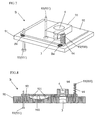
- FIG. 7 is a perspective view of a conventional optical head
- FIG. 8 is a sectional view thereof.
- the optical head B has a base 91 for fitting the collimating lens 3, and an actuator base 92 (hereinafter indicated as act base) which is fitted to the base 91 and on which the objective lens 4 is arranged.
- act base an actuator base 92 (hereinafter indicated as act base) which is fitted to the base 91 and on which the objective lens 4 is arranged.
- the act base 92 is fixed to the base 91 with three sections thereof screwed with, but not limited to, screws 93 in this embodiment.
- one of the screws 93 for fixing the act base 92 is fitted with a spring 94.
- the act base 92 is always biased by the spring 94.
- the objective lens 4 is so arranged by being fitted to a lens fitting part 95, which is then fitted to the act base 92.
- a large truncated spherical recession 911 is formed in the base 91.
- the projections 921 not limited to but three in quantity in this embodiment, are formed which are cut into a spherical shape.
- the curved surface of this projection 921 is arranged in contact with the curved surface of the recession 911.
- the act base 92 smoothly changes its tilt state with respect to the base 91.
- the act base 92 is tilted by adequately operating the screws 931 so that the DVD media is irradiated with laser light emitted from the objective lens 4, with the optical axis thereof perpendicular to the DVD media. Subsequently, an adhesive Be is applied to the side surfaces of the base 91 and the act base 92, whereby the act base 92 is fixed to the base 91. In this manner, the optical head B can be manufactured.
- the collimating lens 3 fitted to the base 91 and the objective lens 4 included in the act base 92 are generally so formed as to be arranged vertically one on another at position where laser light is shined.
- the screws 93 (930, 931), and the recession 911 and the projections 921 may not be arranged at respective positions within the permitted ranges since they cannot be largely shifted.
- An optical head C shown in FIG. 9 has a through hole 811 in a base 81.
- a positioning member 86 penetrating through this through hole 811 is used for positioning.
- the positioning member 86 is formed in a rectangular parallelepiped shape, having on the top thereof two projections 861 formed in a cylindrical shape with a magnet 862 in between.
- locking holes 821 are formed at position in correspondence with the projections 861. The positioning member 86 is penetrated through the through hole 811, then the projections 861 of the positioning member 861 are put into engagement with the locking holes 821 of the act base 82, and then the positioning member 86 and the act base 82 are firmly connected together.
- the positioning member 86 is moved horizontally to move the act base 82 so that the objective lens 4 arranged on the act base 82 is located at such a position as to appropriately receive laser light emerging from the collimating lens 3 fitted to the base 81. Further, moving the positioning member 86 makes adjustment so that the DVD media is irradiated with the laser light emerging from the objective lens 4, with the optical axis thereof perpendicular to the DVD media. Subsequently, upon completion of this adjustment, the adhesive Be is applied to the side surfaces of the base 81 and the act base 82, whereby the act base 82 is fixed to the base 81.
- the invention as described in JP-A-2002-42373 refers to a method of fixing a stator part of an actuator to a frame by inserting a fixing projection through a fixing through hole with an adhesive.
- the position where the act base 82 is to be arranged is determined by use of the positioning member 86, and the act base 82 and the base 81 are bonded together with the adhesive Be.
- a biased stress is imposed on the act base 82 under shrinkage of the adhesive Be or the like.
- the act base 82 moves to a position not determined by the positioning member 86 or is so fixed as to be deformed, thereby leading to performance degradation of the optical head.
- JP-A-2002-42373 discloses a method of inserting a fixing projection through a fixing through hole and then fixing them with an adhesive.
- this provides a structure such that the adhesive tends to flow out of the gap between the fixing projection and the fixing through hole, so that unequal stress is possibly generated due to adhesive condensation.
- the present invention has been made, and it is an object of the invention to provide an optical head that achieves a higher accuracy in bonding between a base on which a collimating lens is arranged and an act base on which an objective lens is arranged, and that is capable of irradiating an optical disc with laser light of a stable intensity, thereby suppressing failure involved in data recording or reading.
- the present invention also relates to an optical disc device adopting such an optical head.
- act base a plurality of through holes to engage with the base are formed in symmetry.
- projection are formed at positions in correspondence with the through holes of the act base in a stepped manner.
- the act base is adjusted so that the tilt angles of the objective lens and the optical disc fall within predetermined ranges, the through holes are engaged with the projections of the base, and an adhesive is injected to the through holes, thereby fixing the act base and the base together.
- an optical disc device which irradiates a discoid optical disc in rotation with laser light to thereby perform data recording or reading, includes an optical head for irradiating the optical disc with laser light, wherein the optical head includes: a laser light source for emitting laser light; a mirror for reflecting the laser light; a collimating lens for converting the laser light into parallel light; an objective lens for irradiating the optical disc with the laser light; a beam splitter for splitting the light reflected on the optical disc; and a light receiving element for receiving the light.
- the collimating lens is supported by a base.
- the objective lens is supported by an act base. In four corners of the act base, through holes to engage with the base are formed.
- projections are formed at positions in correspondence with the through holes of the act base in a stepped manner by coupling together a first cylinder of a larger diameter and a second cylinder of a smaller diameter.
- a recessed groove is formed around the second cylinder.
- the adhesive in connecting and fixing the base and the act base together, the adhesive stays in the through hole of the act base and in the recessed groove of the projections of the base, thereby making it difficult for the adhesive to flow out of the projections.
- through holes to engage with the base are formed.
- projections are formed at positions in correspondence with the through holes of the act base in a stepped manner by coupling together cylinders of different diameters.
- the act base is adjusted so that the tilt angles of the objective lens and the optical disc falls within predetermined ranges, the through holes are engaged with the projections of the base, and an adhesive is injected to the through holes, thereby fixing the act base and the base together.
- the through holes are formed in the four corners of the act base, and the amount of adhesive injected is constant.
- the act base hardly become tilted or deformed due to a stress generated by shrinkage when the adhesive becomes dry.
- the projection is formed on the base by coupling together the cylinders of different diameters, thereby making it easier to manufacture.
- an optical head includes: a laser light source for emitting laser light; a mirror for reflecting the laser light emitted from the laser light source; a collimating lens for converting the laser light reflected by the mirror into parallel light; a base for supporting the collimating lens; an objective lens for irradiating the optical disc with the laser light; an act base for supporting the objective lens; and a light receiving element for receiving the light reflected on the optical disc.
- act base a plurality of through holes to engage with the base are formed in symmetry.
- projections are formed at positions in correspondence with the through holes of the act base in a stepped manner. The act base is adjusted so that the tilt angles of the objective lens and the optical disc falls within predetermined ranges, the through holes are engaged with the projections of the base, and an adhesive is injected to the through holes, thereby fixing the act base and the projections together.
- the through holes of the act base may be formed at four or substantially four corners of the act base.
- the projection of the base can be exemplified by the one formed by coupling together cylinders of different diameters, but the shape thereof is not limited to this.
- the projection may be formed by coupling together cylindrical members having different cross sections.
- a wide variety of members may be used which are capable of engaging with the through hole of the act base, including those sharp-pointed such as cones, pyramids, and like, those having a tapered inclination, and the like.
- a coupling part of the projection has a recessed groove formed therearound where one of the cylinders of the larger diameter couples with another of the cylinders.
- the recessed grooves may be widely used which makes it easy for the adhesive to flow, including those having a cross section of a circular arc, an oval, a rectangle, and the like.
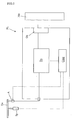
- FIG. 1 is a layout drawing of an optical disc device according to the present invention
- FIG. 2 is a layout drawing of one example of an optical head
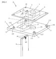
- FIG. 3 is a perspective view of an optical head according to the present invention.
- FIG. 4 is an exploded perspective view of the optical head shown in FIG. 3;
- FIG. 5A to FIG. 5D are sectional views of process of manufacturing the optical head according to the present invention.
- FIG. 6 is a schematic layout drawing of one example of a conventional optical disc device
- FIG. 7 is a perspective view of a conventional optical head
- FIG. 8 is a sectional view of the conventional optical head
- FIG. 9 is a perspective view of the conventional optical head
- FIG. 10 is an enlarged sectional view of one example of a projection provided in the optical head shown in FIG. 3;
- FIG. 11 is an enlarged sectional view of another example of the projection shown in FIG. 10.
- FIG. 1 is a layout drawing of an optical disc device according to the present invention.
- the optical disc device shown in FIG. 1 is, but not limited to, a DVD player in this embodiment.
- the DVD player PL shown in FIG. 1 has substantially the same structure as that of the conventional DVD player PM. That is, the DVD player PL includes: a spindle motor Sp that rotates a DVD media Ds; an optical head A that irradiates the DVD media Ds with light and then reads information thereform; a decoder Dc that decodes a signal detected by the optical head A; an external connector Oc that makes connection with a monitor Mn provided as an external display device; and a controller Cont.
- a spindle motor Sp that rotates a DVD media Ds
- an optical head A that irradiates the DVD media Ds with light and then reads information thereform
- a decoder Dc that decodes a signal detected by the optical head A
- an external connector Oc that makes connection with a monitor Mn provided
- the DVD player PL is controlled by the controller Cont.
- the spindle motor Sp is first driven to thereby rotate the DVD media Ds.
- the optical head A irradiates the DVD media Ds in rotation with laser light, and then detects the light reflected therefrom.
- a light receiving element Pd, to be described below, included in the optical head A converts the detected light into an electrical signal, which is transmitted to the decoder Dc, where the signal is demodulated into a picture signal and then transmitted to the monitor Mn through the external connector Oc, whereby the picture is displayed on the monitor Mn
- FIG. 2 shows a layout drawing of one example of the optical head. More specifically, the optical head has a laser light source Ld, a mirror Mr, a collimating lens 3, an objective lens 4, a beam splitter Bs, and the light receiving element Pd. Laser light emitted from the laser light source Ld is reflected on the mirror Mr, enters the collimating lens 3, transforms into parallel light, and then emerge from the objective lens 4, to be thereby irradiated to the DVD media Ds.
- the beam splitter Bs is a prism that transmits half of incident laser light therethrough and reflects half of the incident laser light and that guides light reflected on the DVD media Ds to the light receiving element Pd.
- the light receiving element Pd converts light into a current, and reads data based on the intensity of light.
- FIG. 3 is a perspective view of the optical head according to the present invention
- FIG. 4 is an exploded perspective view of the optical head shown in FIG. 3.
- the optical head A has a base 1 for supporting the collimating lens 3, and an actuator base 2 for supporting the objective lens 4 which actuator base is fitted to the base 1.
- the act base 2 is formed in, but not limited to, a rectangular shape with through holes 21 formed in the four corners thereof.
- the base 1 has, on the position thereof corresponding to the through holes 21 when the act base 2 is arranged on the base 1, projections 11 to engage with the respective through holes 21. With the through holes 21 of the act base 2 engaged with the respective projections 11 of the base 1, an adhesive Bd is filled to the through holes 21 to thereby fix the act base 2 to the base 1.
- a lens fitting hole 12 for fitting the collimating lens 3 As shown in FIG. 4, in the base 1, there is formed a lens fitting hole 12 for fitting the collimating lens 3. Next to the lens fitting holes 12, a positioning hole 13 is formed in a rectangular shape.
- FIG. 10 is an enlarged sectional view of one example of the projection provided on the optical head shown in FIG. 3 or 4.
- the projection 11 shown in FIG. 10 is formed by combining two cylinders of different diameters, in such a manner that the second projection 112 having a smaller diameter R2 is arranged vertically one on another on the first projection 111 having a larger diameter R1 with the central axes thereof in agreement with each other.
- the first projection 111 is formed in a cylindrical shape having an outer diameter slightly larger than the inner diameter of the through hole 21 of the act base 2.
- the lens fitting part 5 for fitting the objective lens 4 and a light passage hole 22 penetrating through the act base 2 for making laser light from the collimating lens 3 incident on the objective lens 4.
- an engagement part 23, to be described below, for engaging a positioning member 6 is formed.
- the positioning member 6 has a rectangular parallelepiped shape with a top thereof provided with two engaging projections 61 to engage with the engagement part 23 of the act base 2.
- the engaging projections 61 each have a columnar shape. Between the adjacent engaging projections 61, a magnet 62 is arranged. The positioning member 6 engages the engaging projections 61 to the engagement part 23 of the act base 2 and also holds the act base 2 with the magnetic force of the magnet 62.
- FIGS. 5A to 5D sectional views are provided showing process of manufacturing the optical head according to the present invention.
- the direction along the paper surface indicated by the arrow denotes the movement direction. Three-dimensionally speaking, the movement is actually also possible in the direction separating from the paper surface.
- the base 1 is horizontally arranged, and then the act base 2 is arranged on the top of the base 1 with the through holes 21 thereof located in correspondence with the respective projections 11 of the base 1.
- the positioning member 6 is inserted through the positioning hole 13 of the base 1, and the positioning member 6 and the act base 2 are coupled together.
- the positioning member 6 is moved to provide a predetermined positional relationship between the collimating lens 3 fitted to the base 1 and the objective lens 4 mounted on the act base 2.
- the positioning member 6 is moved, with the act base 2 kept in parallel with the base 1.
- the positioning member 6 is movable horizontally within such a range that the second projections 112 formed in the base 1 can engage with the respective through holes 21 of the act base 2 and is also movable in the height direction.
- the positioning member 6 is further moved to swing the act base 2 so that laser light emitted from the objective lens 4 is irradiated to the DVD media Ds at a predetermined angle (with the optical axis perpendicular to the media Ds in this embodiment).
- the positioning member 6 is moved so that the arrangement position of the objective lens 4 is not changed, i.e., the act base 2 swings about the objective lens 4 (see FIG. 2).
- the position of the positioning member 6 is fixed. Then, after confirming that the second projections 112 of the base 1 are in engagement with the respective through holes 21 of the act base 2, the adhesive Bd is injected (see FIG. 5C). After the injection of the adhesive, the positioning member 6 is fixed at the position of FIG. 5C until the adhesive Bd becomes dry, and when the adhesive Bd has become dry, the positioning member 6 is removed, thereby completing the fitting operation (see FIG. 5D).
- the through holes 21 formed in the act base 2 all have the same shape and the same size, and the second projections 112 formed on the base 1 all have the same shape and the same size. Since the act base 2 is arranged in parallel to or slightly at a tilt to the base 1, the second projections 112 engage with the respective through holes 21, and the same or substantially the same amount of the adhesive Bd is injected to each of the through holes 21. Therefore, the stress, which is generated by shrinkage when the adhesive Bd is injected to the through holes 21 becomes dry to be thereby solidified, is evenly applied to the act base 2, thus permitting preventing occurrence of problems such as movement, deformation, and the like.
- FIG. 11 is an enlarged sectional view of another example of the projection shown in FIG. 10.
- the projection shown in FIG. 11 has the same shape as that of the projection shown in FIG. 10 with only different in that the first projection has a recessed groove, and thus the same portions are provided with the same numerals as used in FIG. 10.
- the projection 11B shown in FIG. 11 has a first projection 113 of a large diameter R1 which is integrally formed with the base 1B, and a second projection 114 of a small diameter R2 which is integrally formed with the first projection 113.
- the first projection 113 and the second projection 114 are so formed as to be coaxially coupled together.
- the recessed groove 115 is so formed as to surround the portion coupling with the second projection 114.
- the recessed groove 115 is formed larger than the inner diameter of the through hole 21 in the act base 2.
- the adhesive Bd injected to the through hole 21 flows into the recessed groove 115 formed in first projection 113 of the projection 11B, whereby the adhesive Bd stays in a space 210 formed by the projection 11B and the through hole 21, thereby suppressing the adhesive Bd from dropping from the side surface of the first projection 113.
- the act base 2 is illustrated which has a rectangular shape with the through holes 21 provided in the four corners thereof.
- the shape of the act base 2 is not limited to this, and thus any shape can be widely used which does not cause any problems when arranged on the base.
- an act base can be widely adopted which includes a plurality of through holes located at position that permits supporting the load applied to the act base in a balanced and divided manner.
- an example of the projection 11 of the base 1 is exemplified by the one which is formed by coupling together the cylindrical first projection 111and second projection 112 of different diameters, but the projection 11 is not limited to this example.
- the first projection and the second projection may have different cross sections, and thus the second projection may be adopted which is formed in a sharp-pointed conical shape, a tapered shape, or the like, that can be easily inserted in the through hole 21.
- the second projection can be widely adopted which is capable of providing a stable bonding area when the adhesive Bd is injected to the through hole 21.
- an optical head and an optical disc device employing this optical head can be provided which are capable of improving the accuracy in bonding between a base on which a collimating lens is arranged and an act base on which an objective lens is arranged and which are capable of irradiating an optical disc with laser light of a stable intensity accordingly, thereby suppressing failure in data recording or reading.
Landscapes
- Physics & Mathematics (AREA)
- Optics & Photonics (AREA)
- Optical Head (AREA)
Abstract
Description
- The present invention relates to an optical disc device capable of performing data recording or reading by irradiating an optical disc with light, and more specifically, to an optical head that irradiates the optical disc with light.
- In recent years, as a recording medium for data such as pictures and sounds, optical discs have been widely used which are capable of performing data recording or reading by being irradiated with light. As the optical disc, a CD (compact disc), a DVD (digital versatile disc), and the like are widely used. An optical disc device, which performs data recording or reading on this optical disc as a recording medium, includes an optical head that irradiates the recording surface of the optical disc with laser light and that detects the light reflected therefrom.
- FIG. 6 is a schematic layout drawing of a DVD player as one example of a conventional optical disc device. The DVD player PM shown in FIG. 6 includes: a spindle motor Sp that rotates a DVD media Ds; an optical head B that irradiates the surface of the DVD media Ds with laser light and then detects the light reflected therefrom; a decoder Dc that decodes a signal detected by the optical head B; an external connector Oc that makes connection with an external monitor Mn; and a controller Cont.
- First, the controller Cont drives the spindle motor Sp to thereby rotate the DVD media Ds. The optical head B irradiates the DVD media Ds in rotation with laser light, and then detects the light reflected therefrom. The light detected by the optical head B is transmitted as an electrical signal to the decoder Dc, where the signal is demodulated into a picture signal and then is transmitted to the monitor Mn, whereby the picture is displayed on the monitor Mn.
- FIG. 2 shows a layout drawing of the optical head. The optical head has, as shown in FIG. 2, a laser light source Ld, a mirror Mr, a
collimating lens 3, anobjective lens 4, a beam splitter Bs, and a light receiving element Pd. Laser light emitted from the laser light source Ld is reflected on the mirror Mr and then enters thecollimating lens 3. The laser light entering thecollimating lens 3 then emerges therefrom as parallel light and then enters theobjective lens 4. The laser light entering theobjective lens 4 is irradiated to the recording surface of the DVD media Ds. - At this point, the laser light is irradiated, focusing on a recording layer of the DVD media Ds, so that the optical axis and the recording layer of the DVD media Ds become perpendicular to each other. The beam splitter Bs is a prism that transmits half of incident laser light therethrough and reflects half of the incident laser light and that guides light reflected on the DVD media Ds to the light receiving element Pd. The light receiving element Pd converts light into a current, and reads data based on the intensity of light.
- FIG. 7 is a perspective view of a conventional optical head, and FIG. 8 is a sectional view thereof. As shown in FIG. 7, the optical head B has a
base 91 for fitting thecollimating lens 3, and an actuator base 92 (hereinafter indicated as act base) which is fitted to thebase 91 and on which theobjective lens 4 is arranged. As shown in FIG. 7, theact base 92 is fixed to thebase 91 with three sections thereof screwed with, but not limited to,screws 93 in this embodiment. Considering the symmetry property, one of thescrews 93 for fixing theact base 92 is fitted with aspring 94. Theact base 92 is always biased by thespring 94. Theobjective lens 4 is so arranged by being fitted to a lens fittingpart 95, which is then fitted to theact base 92. - As shown in the sectional view of FIG. 8, in the
base 91, a large truncatedspherical recession 911 is formed. On theact base 92, theprojections 921, not limited to but three in quantity in this embodiment, are formed which are cut into a spherical shape. The curved surface of thisprojection 921 is arranged in contact with the curved surface of therecession 911. As shown in FIG. 8, by tightening and loosening thescrew 93, the curved surface of theprojection 921 moves while making contact with the curved surface of therecession 911, whereby theact base 92 smoothly changes its tilt state with respect to thebase 91. - The
act base 92 is tilted by adequately operating thescrews 931 so that the DVD media is irradiated with laser light emitted from theobjective lens 4, with the optical axis thereof perpendicular to the DVD media. Subsequently, an adhesive Be is applied to the side surfaces of thebase 91 and theact base 92, whereby theact base 92 is fixed to thebase 91. In this manner, the optical head B can be manufactured. - The collimating
lens 3 fitted to thebase 91 and theobjective lens 4 included in theact base 92 are generally so formed as to be arranged vertically one on another at position where laser light is shined. However, when the relative position between the collimatinglens 3 and theobjective lens 4 exceeds the permitted range due to deformation at manufacturing or the like, the screws 93 (930, 931), and therecession 911 and theprojections 921 may not be arranged at respective positions within the permitted ranges since they cannot be largely shifted. - Thus, a three-dimensional bonding method as shown in FIG. 9 may be adopted. An optical head C shown in FIG. 9 has a through
hole 811 in abase 81. Apositioning member 86 penetrating through this throughhole 811 is used for positioning. Thepositioning member 86 is formed in a rectangular parallelepiped shape, having on the top thereof twoprojections 861 formed in a cylindrical shape with amagnet 862 in between. In theact base 82,locking holes 821 are formed at position in correspondence with theprojections 861. Thepositioning member 86 is penetrated through the throughhole 811, then theprojections 861 of thepositioning member 861 are put into engagement with thelocking holes 821 of theact base 82, and then thepositioning member 86 and theact base 82 are firmly connected together. - Subsequently, the
positioning member 86 is moved horizontally to move theact base 82 so that theobjective lens 4 arranged on theact base 82 is located at such a position as to appropriately receive laser light emerging from thecollimating lens 3 fitted to thebase 81. Further, moving thepositioning member 86 makes adjustment so that the DVD media is irradiated with the laser light emerging from theobjective lens 4, with the optical axis thereof perpendicular to the DVD media. Subsequently, upon completion of this adjustment, the adhesive Be is applied to the side surfaces of thebase 81 and theact base 82, whereby theact base 82 is fixed to thebase 81. - The invention as described in JP-A-2002-42373 refers to a method of fixing a stator part of an actuator to a frame by inserting a fixing projection through a fixing through hole with an adhesive.
- However, bonding by use of the
spherical recession 911 and theprojections 921, the screws 93 (930, 931), and thespring 94 cannot support a case where thecollimating lens 3 and theobjective lens 4 are largely dislocated from the designed arrangement position. In case of adjustment made by the screws 93 (930, 931), small adjustment is difficult and the screws 93 (930, 931) cannot be detached after the adjustment; thus, a larger number of components is required accordingly. Moreover, it is difficult to evenly apply the adhesive Be or the like. - With the method shown in FIG. 9, the position where the
act base 82 is to be arranged is determined by use of thepositioning member 86, and theact base 82 and thebase 81 are bonded together with the adhesive Be. In this operation, when it is difficult to apply the adhesive Be or the like evenly to different spots and thus it is not evenly applied, a biased stress is imposed on theact base 82 under shrinkage of the adhesive Be or the like. Under influence of this biased stress, theact base 82 moves to a position not determined by thepositioning member 86 or is so fixed as to be deformed, thereby leading to performance degradation of the optical head. - The invention as described in JP-A-2002-42373 discloses a method of inserting a fixing projection through a fixing through hole and then fixing them with an adhesive. However, this provides a structure such that the adhesive tends to flow out of the gap between the fixing projection and the fixing through hole, so that unequal stress is possibly generated due to adhesive condensation.
- In view of the problem described above, the present invention has been made, and it is an object of the invention to provide an optical head that achieves a higher accuracy in bonding between a base on which a collimating lens is arranged and an act base on which an objective lens is arranged, and that is capable of irradiating an optical disc with laser light of a stable intensity, thereby suppressing failure involved in data recording or reading. The present invention also relates to an optical disc device adopting such an optical head.
- To achieve the object described above, according to one aspect of the present invention, an optical disc device which irradiates a discoid optical disc in rotation with laser light to thereby perform data recording or reading includes an optical head for irradiating the optical disc with laser light, wherein the optical head includes: a laser light source for emitting laser light; a mirror for reflecting the laser light emitted from the laser light source; a collimating lens for converting the laser light reflected by the mirror into parallel light; a base for supporting the collimating lens; an objective lens for irradiating the optical disc with the laser light; an act base for supporting the objective lens; and a light receiving element for receiving the light reflected on the optical disc. In act base, a plurality of through holes to engage with the base are formed in symmetry. In the base, projection are formed at positions in correspondence with the through holes of the act base in a stepped manner. The act base is adjusted so that the tilt angles of the objective lens and the optical disc fall within predetermined ranges, the through holes are engaged with the projections of the base, and an adhesive is injected to the through holes, thereby fixing the act base and the base together.
- According to this configuration, in connecting and fixing the base and the act base together, the projections of the base are engaged with the through holes of the act base and then an adhesive is applied to the through holes. Therefore, the same amount of the adhesive is applied to the through holes.
- Consequently, this permits preventing an unnecessary, uneven stress from being generated in the act base by shrinkage when the adhesive becomes dry. The prevention of an uneven stress in turn permits preventing a shift in the positional relationship between the base and the act base determined before bonding. Moreover, since no uneven stress is imposed on the act base, the deformation of the act base itself can be prevented. Further, the capability of irradiating the optical disc with optimum laser light permits stable data recording or reading.
- To achieve the object described above, according to another aspect of the invention, an optical disc device, which irradiates a discoid optical disc in rotation with laser light to thereby perform data recording or reading, includes an optical head for irradiating the optical disc with laser light, wherein the optical head includes: a laser light source for emitting laser light; a mirror for reflecting the laser light; a collimating lens for converting the laser light into parallel light; an objective lens for irradiating the optical disc with the laser light; a beam splitter for splitting the light reflected on the optical disc; and a light receiving element for receiving the light. The collimating lens is supported by a base. The objective lens is supported by an act base. In four corners of the act base, through holes to engage with the base are formed. In the base, projections are formed at positions in correspondence with the through holes of the act base in a stepped manner by coupling together a first cylinder of a larger diameter and a second cylinder of a smaller diameter. In a portion of the first cylinder coupling with the second cylinder, a recessed groove is formed around the second cylinder. The act base is adjusted so that the tilt angles of the objective lens and the optical disc falls within predetermined ranges, the through holes are engaged with the projections of the base, and an adhesive is injected to the through holes, thereby fixing the act base and the base together.
- According to this configuration, in connecting and fixing the base and the act base together, the adhesive stays in the through hole of the act base and in the recessed groove of the projections of the base, thereby making it difficult for the adhesive to flow out of the projections.
- Consequently, this permits preventing an unnecessary, uneven stress from being generated in the act base by shrinkage when the adhesive becomes dry. The prevention of an uneven stress in turn permits preventing a shift in the positional relationship between the base and the act base determined before bonding. Moreover, since no uneven stress is imposed on the act base, the deformation of the act base itself can be prevented. Further, the capability of irradiating the optical disc with optimum laser light permits stable data recording or reading.
- To achieve the object described above, according to still another aspect of the present invention, an optical disc device which irradiates a discoid optical disc in rotation with laser light to thereby perform data recording or reading includes an optical head for irradiating the optical disc with laser light, wherein the optical head includes: a laser light source for emitting laser light; a mirror for reflecting the laser light emitted from the laser light source; a collimating lens for converting the laser light reflected by the mirror into parallel light; a base for supporting the collimating lens; an objective lens for irradiating the optical disc with the laser light; an act base for supporting the objective lens; and a light receiving element for receiving the light reflected on the optical disc. In four corners of the act base, through holes to engage with the base are formed. In the base, projections are formed at positions in correspondence with the through holes of the act base in a stepped manner by coupling together cylinders of different diameters. The act base is adjusted so that the tilt angles of the objective lens and the optical disc falls within predetermined ranges, the through holes are engaged with the projections of the base, and an adhesive is injected to the through holes, thereby fixing the act base and the base together.
- According to this configuration, the through holes are formed in the four corners of the act base, and the amount of adhesive injected is constant. Thus, the act base hardly become tilted or deformed due to a stress generated by shrinkage when the adhesive becomes dry. Moreover, the projection is formed on the base by coupling together the cylinders of different diameters, thereby making it easier to manufacture.
- To achieve the object described above, according to still another aspect of the invention, an optical head includes: a laser light source for emitting laser light; a mirror for reflecting the laser light emitted from the laser light source; a collimating lens for converting the laser light reflected by the mirror into parallel light; a base for supporting the collimating lens; an objective lens for irradiating the optical disc with the laser light; an act base for supporting the objective lens; and a light receiving element for receiving the light reflected on the optical disc. In act base, a plurality of through holes to engage with the base are formed in symmetry. In the base, projections are formed at positions in correspondence with the through holes of the act base in a stepped manner. The act base is adjusted so that the tilt angles of the objective lens and the optical disc falls within predetermined ranges, the through holes are engaged with the projections of the base, and an adhesive is injected to the through holes, thereby fixing the act base and the projections together.
- According to this configuration, in connecting and fixing the base and the act base together, the projections of the base are engaged with the through holes of the act base and then the adhesive is applied to the through holes. Therefore, the same amount of the adhesive is applied to the through holes.
- Consequently, this permits preventing an unnecessary, uneven stress from being generated in the act base by shrinkage when the adhesive becomes dry. The prevention of an uneven stress in turn permits preventing a shift in the positional relationship, determined before bonding, between the base and the act base. Moreover, since no uneven stress is imposed on the act base, the deformation of the act base itself can be prevented. Further, the capability of irradiating the optical disc with optimum laser light permits stable data recording or reading.
- In the configuration described above, the through holes of the act base may be formed at four or substantially four corners of the act base. The projection of the base can be exemplified by the one formed by coupling together cylinders of different diameters, but the shape thereof is not limited to this. Alternatively, the projection may be formed by coupling together cylindrical members having different cross sections. Moreover, a wide variety of members may be used which are capable of engaging with the through hole of the act base, including those sharp-pointed such as cones, pyramids, and like, those having a tapered inclination, and the like.
- Further, a coupling part of the projection has a recessed groove formed therearound where one of the cylinders of the larger diameter couples with another of the cylinders. The recessed grooves may be widely used which makes it easy for the adhesive to flow, including those having a cross section of a circular arc, an oval, a rectangle, and the like.
- The above and other objects of the present invention will be more clarified with reference to the preferred embodiments to be described below and the accompanying drawings showing the forllowimng:
- FIG. 1 is a layout drawing of an optical disc device according to the present invention;
- FIG. 2 is a layout drawing of one example of an optical head;
- FIG. 3 is a perspective view of an optical head according to the present invention;
- FIG. 4 is an exploded perspective view of the optical head shown in FIG. 3;
- FIG. 5A to FIG. 5D are sectional views of process of manufacturing the optical head according to the present invention;
- FIG. 6 is a schematic layout drawing of one example of a conventional optical disc device;
- FIG. 7 is a perspective view of a conventional optical head;
- FIG. 8 is a sectional view of the conventional optical head;
- FIG. 9 is a perspective view of the conventional optical head;
- FIG. 10 is an enlarged sectional view of one example of a projection provided in the optical head shown in FIG. 3; and
- FIG. 11 is an enlarged sectional view of another example of the projection shown in FIG. 10.
- Hereinafter, the embodiment of the present invention will be described with reference to the accompanying drawings. FIG. 1 is a layout drawing of an optical disc device according to the present invention. The optical disc device shown in FIG. 1 is, but not limited to, a DVD player in this embodiment. The DVD player PL shown in FIG. 1 has substantially the same structure as that of the conventional DVD player PM. That is, the DVD player PL includes: a spindle motor Sp that rotates a DVD media Ds; an optical head A that irradiates the DVD media Ds with light and then reads information thereform; a decoder Dc that decodes a signal detected by the optical head A; an external connector Oc that makes connection with a monitor Mn provided as an external display device; and a controller Cont.
- The DVD player PL is controlled by the controller Cont. Upon command from the user for reproducing the DVD, the spindle motor Sp is first driven to thereby rotate the DVD media Ds. The optical head A irradiates the DVD media Ds in rotation with laser light, and then detects the light reflected therefrom. A light receiving element Pd, to be described below, included in the optical head A converts the detected light into an electrical signal, which is transmitted to the decoder Dc, where the signal is demodulated into a picture signal and then transmitted to the monitor Mn through the external connector Oc, whereby the picture is displayed on the monitor Mn
- FIG. 2 shows a layout drawing of one example of the optical head. More specifically, the optical head has a laser light source Ld, a mirror Mr, a
collimating lens 3, anobjective lens 4, a beam splitter Bs, and the light receiving element Pd. Laser light emitted from the laser light source Ld is reflected on the mirror Mr, enters thecollimating lens 3, transforms into parallel light, and then emerge from theobjective lens 4, to be thereby irradiated to the DVD media Ds. - At this point, the laser light is irradiated, focusing on a recording layer of the DVD media Ds, so that the optical axis and the recording layer of the DVD media Ds become perpendicular to each other. The beam splitter Bs is a prism that transmits half of incident laser light therethrough and reflects half of the incident laser light and that guides light reflected on the DVD media Ds to the light receiving element Pd. The light receiving element Pd converts light into a current, and reads data based on the intensity of light.
- FIG. 3 is a perspective view of the optical head according to the present invention, and FIG. 4 is an exploded perspective view of the optical head shown in FIG. 3. As shown in FIG. 3, the optical head A has a
base 1 for supporting thecollimating lens 3, and anactuator base 2 for supporting theobjective lens 4 which actuator base is fitted to thebase 1. Theact base 2 is formed in, but not limited to, a rectangular shape with throughholes 21 formed in the four corners thereof. Thebase 1 has, on the position thereof corresponding to the throughholes 21 when theact base 2 is arranged on thebase 1,projections 11 to engage with the respective throughholes 21. With the throughholes 21 of theact base 2 engaged with therespective projections 11 of thebase 1, an adhesive Bd is filled to the throughholes 21 to thereby fix theact base 2 to thebase 1. - As shown in FIG. 4, in the
base 1, there is formed a lensfitting hole 12 for fitting thecollimating lens 3. Next to the lens fitting holes 12, apositioning hole 13 is formed in a rectangular shape. - FIG. 10 is an enlarged sectional view of one example of the projection provided on the optical head shown in FIG. 3 or 4. The
projection 11 shown in FIG. 10 is formed by combining two cylinders of different diameters, in such a manner that thesecond projection 112 having a smaller diameter R2 is arranged vertically one on another on thefirst projection 111 having a larger diameter R1 with the central axes thereof in agreement with each other. Thefirst projection 111 is formed in a cylindrical shape having an outer diameter slightly larger than the inner diameter of the throughhole 21 of theact base 2. - In the
act base 2, there are formed: the lensfitting part 5 for fitting theobjective lens 4 and alight passage hole 22 penetrating through theact base 2 for making laser light from thecollimating lens 3 incident on theobjective lens 4. Next to thelight passage hole 22, anengagement part 23, to be described below, for engaging apositioning member 6 is formed. The positioningmember 6 has a rectangular parallelepiped shape with a top thereof provided with twoengaging projections 61 to engage with theengagement part 23 of theact base 2. The engagingprojections 61 each have a columnar shape. Between the adjacentengaging projections 61, amagnet 62 is arranged. The positioningmember 6 engages the engagingprojections 61 to theengagement part 23 of theact base 2 and also holds theact base 2 with the magnetic force of themagnet 62. - In FIGS. 5A to 5D, sectional views are provided showing process of manufacturing the optical head according to the present invention. In FIGS. 5A to 5D, the direction along the paper surface indicated by the arrow denotes the movement direction. Three-dimensionally speaking, the movement is actually also possible in the direction separating from the paper surface. As shown in FIG. 5A, the
base 1 is horizontally arranged, and then theact base 2 is arranged on the top of thebase 1 with the throughholes 21 thereof located in correspondence with therespective projections 11 of thebase 1. Subsequently, the positioningmember 6 is inserted through thepositioning hole 13 of thebase 1, and thepositioning member 6 and theact base 2 are coupled together. As shown in FIGS. 5A to 5D, the positioningmember 6 is moved to provide a predetermined positional relationship between thecollimating lens 3 fitted to thebase 1 and theobjective lens 4 mounted on theact base 2. - In this condition, the positioning
member 6 is moved, with theact base 2 kept in parallel with thebase 1. The positioningmember 6 is movable horizontally within such a range that thesecond projections 112 formed in thebase 1 can engage with the respective throughholes 21 of theact base 2 and is also movable in the height direction. After arranging theact base 2 on the top of thebase 1 by the positioningmember 6, the positioningmember 6 is further moved to swing theact base 2 so that laser light emitted from theobjective lens 4 is irradiated to the DVD media Ds at a predetermined angle (with the optical axis perpendicular to the media Ds in this embodiment). In this operation, the positioningmember 6 is moved so that the arrangement position of theobjective lens 4 is not changed, i.e., theact base 2 swings about the objective lens 4 (see FIG. 2). - After the positioning of the
act base 2, the position of thepositioning member 6 is fixed. Then, after confirming that thesecond projections 112 of thebase 1 are in engagement with the respective throughholes 21 of theact base 2, the adhesive Bd is injected (see FIG. 5C). After the injection of the adhesive, the positioningmember 6 is fixed at the position of FIG. 5C until the adhesive Bd becomes dry, and when the adhesive Bd has become dry, the positioningmember 6 is removed, thereby completing the fitting operation (see FIG. 5D). - The through holes 21 formed in the
act base 2 all have the same shape and the same size, and thesecond projections 112 formed on thebase 1 all have the same shape and the same size. Since theact base 2 is arranged in parallel to or slightly at a tilt to thebase 1, thesecond projections 112 engage with the respective throughholes 21, and the same or substantially the same amount of the adhesive Bd is injected to each of the through holes 21. Therefore, the stress, which is generated by shrinkage when the adhesive Bd is injected to the throughholes 21 becomes dry to be thereby solidified, is evenly applied to theact base 2, thus permitting preventing occurrence of problems such as movement, deformation, and the like. - FIG. 11 is an enlarged sectional view of another example of the projection shown in FIG. 10. The projection shown in FIG. 11 has the same shape as that of the projection shown in FIG. 10 with only different in that the first projection has a recessed groove, and thus the same portions are provided with the same numerals as used in FIG. 10. The
projection 11B shown in FIG. 11 has afirst projection 113 of a large diameter R1 which is integrally formed with thebase 1B, and asecond projection 114 of a small diameter R2 which is integrally formed with thefirst projection 113. Thefirst projection 113 and thesecond projection 114 are so formed as to be coaxially coupled together. - In the surface of the
first projection 113 which is coupled with thesecond projection 114, the recessedgroove 115 is so formed as to surround the portion coupling with thesecond projection 114. The recessedgroove 115 is formed larger than the inner diameter of the throughhole 21 in theact base 2. - In fitting the
act base 2 to thebase 1B, after adjusting the tilt of theact base 2, the arrangement is achieved so that theprojection 11B of thebase 1B is inserted in the throughhole 21 of theact base 2. After theprojection 11B is inserted in the throughhole 21, the adhesive Bd is injected to the throughhole 21 from thereabove. - The adhesive Bd injected to the through
hole 21 flows into the recessedgroove 115 formed infirst projection 113 of theprojection 11B, whereby the adhesive Bd stays in aspace 210 formed by theprojection 11B and the throughhole 21, thereby suppressing the adhesive Bd from dropping from the side surface of thefirst projection 113. - This therefore permits achieving substantially the same adhesion state of the adhesive Bd in all the through
holes 21 formed in theact base 2. Thus, the stress, which is generated by shrinkage when the adhesive Bd becomes dry to be thereby solidified, is evenly applied to theact base 2, thereby permitting preventing occurrence of problems such as movement, deformation, and the like. - In the embodiment described above, the
act base 2 is illustrated which has a rectangular shape with the throughholes 21 provided in the four corners thereof. However, the shape of theact base 2 is not limited to this, and thus any shape can be widely used which does not cause any problems when arranged on the base. Moreover, in this condition, an act base can be widely adopted which includes a plurality of through holes located at position that permits supporting the load applied to the act base in a balanced and divided manner. - In the embodiment described above, an example of the
projection 11 of thebase 1 is exemplified by the one which is formed by coupling together the cylindrical first projection 111andsecond projection 112 of different diameters, but theprojection 11 is not limited to this example. For example, the first projection and the second projection may have different cross sections, and thus the second projection may be adopted which is formed in a sharp-pointed conical shape, a tapered shape, or the like, that can be easily inserted in the throughhole 21. Thus, the second projection can be widely adopted which is capable of providing a stable bonding area when the adhesive Bd is injected to the throughhole 21. - According to the present invention described above referring to the embodiment, an optical head and an optical disc device employing this optical head can be provided which are capable of improving the accuracy in bonding between a base on which a collimating lens is arranged and an act base on which an objective lens is arranged and which are capable of irradiating an optical disc with laser light of a stable intensity accordingly, thereby suppressing failure in data recording or reading.
Claims (5)
- An optical head comprising:a laser light source for emitting laser light;a mirror for reflecting the laser light;a collimating lens (3) for converting the laser light into parallel light; an objectivelens (4) for irradiating an optical disc with the laser light;a beam splitter for splitting the light reflected on the optical disc; anda light receiving element for receiving the light,the optical head being characterized in that
the collimating lens (3) is supported by a base (1),
the objective lens (3) is supported by an act base (2),
in the act base (2), a plurality of through holes (21) to engage with the base (1) are so formed as to be in symmetry,
in the base (1), projections (11) are formed in a stepped manner at positions in correspondence with the through holes (21) of the act base (2), and
the act base (2) is adjusted so that tilt angles of the objective lens (4) and the optical disc fall within predetermined ranges, the through holes (21) are engaged with the projections (11) of the base (1), and an adhesive is injected to the through holes (21), thereby fixing the act base (2) and the projections together (11). - The optical head according to claim 1, characterized in that
the through holes (21) of the act base (2) are formed at four or substantially four corners of the act base (2). - The optical head according to claim 1 or 2, characterized in that
the projection of the base (1) is formed by coupling together cylinders of different diameters. - The optical head according to any of claims 1 to 3, characterized in that
a coupling part of the projection has a recessed groove formed therearound where one of the cylinders of the larger diameter couples with another of the cylinders. - An optical disc device, characterized in that
a discoid optical disc in rotation is irradiated with laser light to thereby perform data recording or reading, and that the optical head according to any of the preceding claims is included which irradiates the optical disc with laser light.
Applications Claiming Priority (1)
| Application Number | Priority Date | Filing Date | Title |
|---|---|---|---|
| JP2005058283A JP3937441B2 (en) | 2004-10-14 | 2005-03-03 | Optical head and optical disk apparatus |
Publications (2)
| Publication Number | Publication Date |
|---|---|
| EP1699046A1 true EP1699046A1 (en) | 2006-09-06 |
| EP1699046B1 EP1699046B1 (en) | 2007-10-17 |
Family
ID=36593062
Family Applications (1)
| Application Number | Title | Priority Date | Filing Date |
|---|---|---|---|
| EP06004399A Expired - Lifetime EP1699046B1 (en) | 2005-03-03 | 2006-03-03 | Optical head and optical disc device provided therewith |
Country Status (4)
| Country | Link |
|---|---|
| US (1) | US7668048B2 (en) |
| EP (1) | EP1699046B1 (en) |
| CN (1) | CN100367385C (en) |
| DE (1) | DE602006000162T2 (en) |
Families Citing this family (2)
| Publication number | Priority date | Publication date | Assignee | Title |
|---|---|---|---|---|
| US7974106B2 (en) * | 2007-05-07 | 2011-07-05 | Bloom Energy Corporation | Ripple cancellation |
| JP5135375B2 (en) * | 2010-03-31 | 2013-02-06 | 京セラドキュメントソリューションズ株式会社 | Image reading apparatus and image forming apparatus using the same |
Citations (7)
| Publication number | Priority date | Publication date | Assignee | Title |
|---|---|---|---|---|
| EP0649130A1 (en) * | 1993-10-15 | 1995-04-19 | Kabushiki Kaisha Kenwood | Objective lens posture adjusting mechanism for optical pickup |
| JP2002042373A (en) * | 2000-07-24 | 2002-02-08 | Ricoh Co Ltd | Lens actuator structure |
| US20020021631A1 (en) * | 1998-11-17 | 2002-02-21 | Fujitsu Limited | Actuator for optical pickup |
| US20040081062A1 (en) * | 2002-07-04 | 2004-04-29 | Naohiro Netsu | Optical pickup apparatus and signal recording and/or reproducing apparatus |
| US20040095869A1 (en) * | 2002-11-15 | 2004-05-20 | Sharp Kabushiki Kaisha | Optical pickup device and method and apparatus for assembling the same |
| US20040103421A1 (en) * | 1999-02-24 | 2004-05-27 | Matsushita Electric Industrial Co., Ltd. | Optical head and method of manufacturing the same |
| US20050015790A1 (en) * | 2003-07-18 | 2005-01-20 | Sharp Kabushiki Kaisha | Optical pickup and manufacturing method thereof |
Family Cites Families (2)
| Publication number | Priority date | Publication date | Assignee | Title |
|---|---|---|---|---|
| JP3841217B2 (en) * | 2003-06-17 | 2006-11-01 | 船井電機株式会社 | Optical pickup |
| EP1551013B1 (en) * | 2003-12-29 | 2009-03-18 | LG Electronics Inc. | Optical pick-up actuator |
-
2006
- 2006-03-01 CN CNB2006100198874A patent/CN100367385C/en not_active Expired - Fee Related
- 2006-03-03 US US11/366,525 patent/US7668048B2/en not_active Expired - Fee Related
- 2006-03-03 EP EP06004399A patent/EP1699046B1/en not_active Expired - Lifetime
- 2006-03-03 DE DE602006000162T patent/DE602006000162T2/en not_active Expired - Lifetime
Patent Citations (7)
| Publication number | Priority date | Publication date | Assignee | Title |
|---|---|---|---|---|
| EP0649130A1 (en) * | 1993-10-15 | 1995-04-19 | Kabushiki Kaisha Kenwood | Objective lens posture adjusting mechanism for optical pickup |
| US20020021631A1 (en) * | 1998-11-17 | 2002-02-21 | Fujitsu Limited | Actuator for optical pickup |
| US20040103421A1 (en) * | 1999-02-24 | 2004-05-27 | Matsushita Electric Industrial Co., Ltd. | Optical head and method of manufacturing the same |
| JP2002042373A (en) * | 2000-07-24 | 2002-02-08 | Ricoh Co Ltd | Lens actuator structure |
| US20040081062A1 (en) * | 2002-07-04 | 2004-04-29 | Naohiro Netsu | Optical pickup apparatus and signal recording and/or reproducing apparatus |
| US20040095869A1 (en) * | 2002-11-15 | 2004-05-20 | Sharp Kabushiki Kaisha | Optical pickup device and method and apparatus for assembling the same |
| US20050015790A1 (en) * | 2003-07-18 | 2005-01-20 | Sharp Kabushiki Kaisha | Optical pickup and manufacturing method thereof |
Non-Patent Citations (1)
| Title |
|---|
| PATENT ABSTRACTS OF JAPAN vol. 2002, no. 06 4 June 2002 (2002-06-04) * |
Also Published As
| Publication number | Publication date |
|---|---|
| US7668048B2 (en) | 2010-02-23 |
| CN100367385C (en) | 2008-02-06 |
| CN1828746A (en) | 2006-09-06 |
| EP1699046B1 (en) | 2007-10-17 |
| DE602006000162T2 (en) | 2008-08-07 |
| DE602006000162D1 (en) | 2007-11-29 |
| US20060198255A1 (en) | 2006-09-07 |
Similar Documents
| Publication | Publication Date | Title |
|---|---|---|
| JP2006019001A (en) | Optical pickup and lens assembling apparatus and method | |
| EP1909274A1 (en) | Optical pickup | |
| US7852737B2 (en) | Optical pickup | |
| EP1699046B1 (en) | Optical head and optical disc device provided therewith | |
| JP2004146049A (en) | Compatible optical pickup device, optical recording / reproducing device employing the same, and actuator for compatible optical pickup device | |
| JP3937441B2 (en) | Optical head and optical disk apparatus | |
| JP5065035B2 (en) | Optical head device | |
| US6993825B2 (en) | Tilt adjusting method for guide shafts in a recording medium driving apparatus | |
| JP2006041042A (en) | Laser diode optical axis adjustment structure and optical pickup device | |
| JP2005293707A (en) | Optical pickup device | |
| CN101587220A (en) | Lens driver | |
| JP2005293686A (en) | Optical pickup device | |
| JP4591688B2 (en) | Optical head and optical disc apparatus provided with the same | |
| JP2008065889A (en) | Optical pickup device and manufacturing method thereof | |
| EP1909273A1 (en) | Optical pickup and manufacturing method for optical pickup | |
| KR100569375B1 (en) | Anti-rotation structure of the optical pickup actuator | |
| JP3111412U (en) | Optical head and optical disk apparatus | |
| JP2011060375A (en) | Disk device | |
| JP2010134995A (en) | Lens position adjusting mechanism for optical pickup device, the optical pickup device, optical disk device, and lens position adjusting method for the optical pickup device | |
| JP4697173B2 (en) | Optical pickup | |
| KR100197943B1 (en) | Objective coupling structure of axial perturbation actuator | |
| JP2007058898A (en) | Optical head | |
| JP2007141359A (en) | Optical head adjusting device and optical head adjusting method using the same | |
| JP2008146799A (en) | Lens actuator, optical pickup device, and optical recording / reproducing device | |
| JP2007004848A (en) | Optical pickup device |
Legal Events
| Date | Code | Title | Description |
|---|---|---|---|
| PUAI | Public reference made under article 153(3) epc to a published international application that has entered the european phase |
Free format text: ORIGINAL CODE: 0009012 |
|
| AK | Designated contracting states |
Kind code of ref document: A1 Designated state(s): AT BE BG CH CY CZ DE DK EE ES FI FR GB GR HU IE IS IT LI LT LU LV MC NL PL PT RO SE SI SK TR |
|
| AX | Request for extension of the european patent |
Extension state: AL BA HR MK YU |
|
| GRAP | Despatch of communication of intention to grant a patent |
Free format text: ORIGINAL CODE: EPIDOSNIGR1 |
|
| 17P | Request for examination filed |
Effective date: 20070306 |
|
| AKX | Designation fees paid |
Designated state(s): DE FR GB |
|
| GRAS | Grant fee paid |
Free format text: ORIGINAL CODE: EPIDOSNIGR3 |
|
| GRAA | (expected) grant |
Free format text: ORIGINAL CODE: 0009210 |
|
| AK | Designated contracting states |
Kind code of ref document: B1 Designated state(s): DE FR GB |
|
| REG | Reference to a national code |
Ref country code: GB Ref legal event code: FG4D |
|
| REF | Corresponds to: |
Ref document number: 602006000162 Country of ref document: DE Date of ref document: 20071129 Kind code of ref document: P |
|
| ET | Fr: translation filed | ||
| PLBE | No opposition filed within time limit |
Free format text: ORIGINAL CODE: 0009261 |
|
| STAA | Information on the status of an ep patent application or granted ep patent |
Free format text: STATUS: NO OPPOSITION FILED WITHIN TIME LIMIT |
|
| 26N | No opposition filed |
Effective date: 20080718 |
|
| REG | Reference to a national code |
Ref country code: FR Ref legal event code: PLFP Year of fee payment: 11 |
|
| PGFP | Annual fee paid to national office [announced via postgrant information from national office to epo] |
Ref country code: DE Payment date: 20160223 Year of fee payment: 11 |
|
| PGFP | Annual fee paid to national office [announced via postgrant information from national office to epo] |
Ref country code: GB Payment date: 20160302 Year of fee payment: 11 Ref country code: FR Payment date: 20160208 Year of fee payment: 11 |
|
| REG | Reference to a national code |
Ref country code: DE Ref legal event code: R119 Ref document number: 602006000162 Country of ref document: DE |
|
| GBPC | Gb: european patent ceased through non-payment of renewal fee |
Effective date: 20170303 |
|
| REG | Reference to a national code |
Ref country code: FR Ref legal event code: ST Effective date: 20171130 |
|
| PG25 | Lapsed in a contracting state [announced via postgrant information from national office to epo] |
Ref country code: DE Free format text: LAPSE BECAUSE OF NON-PAYMENT OF DUE FEES Effective date: 20171003 Ref country code: FR Free format text: LAPSE BECAUSE OF NON-PAYMENT OF DUE FEES Effective date: 20170331 |
|
| PG25 | Lapsed in a contracting state [announced via postgrant information from national office to epo] |
Ref country code: GB Free format text: LAPSE BECAUSE OF NON-PAYMENT OF DUE FEES Effective date: 20170303 |